EP2348562A1 - Electrode assembly, method of manufacturing electrode assembly, and secondary battery including electrode assembly - Google Patents
Electrode assembly, method of manufacturing electrode assembly, and secondary battery including electrode assembly Download PDFInfo
- Publication number
- EP2348562A1 EP2348562A1 EP11150192A EP11150192A EP2348562A1 EP 2348562 A1 EP2348562 A1 EP 2348562A1 EP 11150192 A EP11150192 A EP 11150192A EP 11150192 A EP11150192 A EP 11150192A EP 2348562 A1 EP2348562 A1 EP 2348562A1
- Authority
- EP
- European Patent Office
- Prior art keywords
- electrode
- electrode assembly
- roll
- electrodes
- coated portion
- Prior art date
- Legal status (The legal status is an assumption and is not a legal conclusion. Google has not performed a legal analysis and makes no representation as to the accuracy of the status listed.)
- Withdrawn
Links
Images



Classifications
-
- H—ELECTRICITY
- H01—ELECTRIC ELEMENTS
- H01M—PROCESSES OR MEANS, e.g. BATTERIES, FOR THE DIRECT CONVERSION OF CHEMICAL ENERGY INTO ELECTRICAL ENERGY
- H01M50/00—Constructional details or processes of manufacture of the non-active parts of electrochemical cells other than fuel cells, e.g. hybrid cells
- H01M50/40—Separators; Membranes; Diaphragms; Spacing elements inside cells
- H01M50/46—Separators, membranes or diaphragms characterised by their combination with electrodes
-
- H—ELECTRICITY
- H01—ELECTRIC ELEMENTS
- H01M—PROCESSES OR MEANS, e.g. BATTERIES, FOR THE DIRECT CONVERSION OF CHEMICAL ENERGY INTO ELECTRICAL ENERGY
- H01M10/00—Secondary cells; Manufacture thereof
- H01M10/04—Construction or manufacture in general
- H01M10/0431—Cells with wound or folded electrodes
-
- H—ELECTRICITY
- H01—ELECTRIC ELEMENTS
- H01M—PROCESSES OR MEANS, e.g. BATTERIES, FOR THE DIRECT CONVERSION OF CHEMICAL ENERGY INTO ELECTRICAL ENERGY
- H01M10/00—Secondary cells; Manufacture thereof
- H01M10/42—Methods or arrangements for servicing or maintenance of secondary cells or secondary half-cells
- H01M10/425—Structural combination with electronic components, e.g. electronic circuits integrated to the outside of the casing
-
- H—ELECTRICITY
- H01—ELECTRIC ELEMENTS
- H01M—PROCESSES OR MEANS, e.g. BATTERIES, FOR THE DIRECT CONVERSION OF CHEMICAL ENERGY INTO ELECTRICAL ENERGY
- H01M4/00—Electrodes
- H01M4/02—Electrodes composed of, or comprising, active material
-
- H—ELECTRICITY
- H01—ELECTRIC ELEMENTS
- H01M—PROCESSES OR MEANS, e.g. BATTERIES, FOR THE DIRECT CONVERSION OF CHEMICAL ENERGY INTO ELECTRICAL ENERGY
- H01M50/00—Constructional details or processes of manufacture of the non-active parts of electrochemical cells other than fuel cells, e.g. hybrid cells
- H01M50/10—Primary casings; Jackets or wrappings
- H01M50/102—Primary casings; Jackets or wrappings characterised by their shape or physical structure
- H01M50/103—Primary casings; Jackets or wrappings characterised by their shape or physical structure prismatic or rectangular
-
- H—ELECTRICITY
- H01—ELECTRIC ELEMENTS
- H01M—PROCESSES OR MEANS, e.g. BATTERIES, FOR THE DIRECT CONVERSION OF CHEMICAL ENERGY INTO ELECTRICAL ENERGY
- H01M50/00—Constructional details or processes of manufacture of the non-active parts of electrochemical cells other than fuel cells, e.g. hybrid cells
- H01M50/10—Primary casings; Jackets or wrappings
- H01M50/102—Primary casings; Jackets or wrappings characterised by their shape or physical structure
- H01M50/105—Pouches or flexible bags
-
- H—ELECTRICITY
- H01—ELECTRIC ELEMENTS
- H01M—PROCESSES OR MEANS, e.g. BATTERIES, FOR THE DIRECT CONVERSION OF CHEMICAL ENERGY INTO ELECTRICAL ENERGY
- H01M50/00—Constructional details or processes of manufacture of the non-active parts of electrochemical cells other than fuel cells, e.g. hybrid cells
- H01M50/50—Current conducting connections for cells or batteries
- H01M50/531—Electrode connections inside a battery casing
- H01M50/538—Connection of several leads or tabs of wound or folded electrode stacks
-
- H—ELECTRICITY
- H01—ELECTRIC ELEMENTS
- H01M—PROCESSES OR MEANS, e.g. BATTERIES, FOR THE DIRECT CONVERSION OF CHEMICAL ENERGY INTO ELECTRICAL ENERGY
- H01M50/00—Constructional details or processes of manufacture of the non-active parts of electrochemical cells other than fuel cells, e.g. hybrid cells
- H01M50/50—Current conducting connections for cells or batteries
- H01M50/543—Terminals
-
- H—ELECTRICITY
- H01—ELECTRIC ELEMENTS
- H01M—PROCESSES OR MEANS, e.g. BATTERIES, FOR THE DIRECT CONVERSION OF CHEMICAL ENERGY INTO ELECTRICAL ENERGY
- H01M10/00—Secondary cells; Manufacture thereof
- H01M10/05—Accumulators with non-aqueous electrolyte
- H01M10/058—Construction or manufacture
- H01M10/0587—Construction or manufacture of accumulators having only wound construction elements, i.e. wound positive electrodes, wound negative electrodes and wound separators
-
- Y—GENERAL TAGGING OF NEW TECHNOLOGICAL DEVELOPMENTS; GENERAL TAGGING OF CROSS-SECTIONAL TECHNOLOGIES SPANNING OVER SEVERAL SECTIONS OF THE IPC; TECHNICAL SUBJECTS COVERED BY FORMER USPC CROSS-REFERENCE ART COLLECTIONS [XRACs] AND DIGESTS
- Y02—TECHNOLOGIES OR APPLICATIONS FOR MITIGATION OR ADAPTATION AGAINST CLIMATE CHANGE
- Y02E—REDUCTION OF GREENHOUSE GAS [GHG] EMISSIONS, RELATED TO ENERGY GENERATION, TRANSMISSION OR DISTRIBUTION
- Y02E60/00—Enabling technologies; Technologies with a potential or indirect contribution to GHG emissions mitigation
- Y02E60/10—Energy storage using batteries
-
- Y—GENERAL TAGGING OF NEW TECHNOLOGICAL DEVELOPMENTS; GENERAL TAGGING OF CROSS-SECTIONAL TECHNOLOGIES SPANNING OVER SEVERAL SECTIONS OF THE IPC; TECHNICAL SUBJECTS COVERED BY FORMER USPC CROSS-REFERENCE ART COLLECTIONS [XRACs] AND DIGESTS
- Y02—TECHNOLOGIES OR APPLICATIONS FOR MITIGATION OR ADAPTATION AGAINST CLIMATE CHANGE
- Y02P—CLIMATE CHANGE MITIGATION TECHNOLOGIES IN THE PRODUCTION OR PROCESSING OF GOODS
- Y02P70/00—Climate change mitigation technologies in the production process for final industrial or consumer products
- Y02P70/50—Manufacturing or production processes characterised by the final manufactured product
-
- Y—GENERAL TAGGING OF NEW TECHNOLOGICAL DEVELOPMENTS; GENERAL TAGGING OF CROSS-SECTIONAL TECHNOLOGIES SPANNING OVER SEVERAL SECTIONS OF THE IPC; TECHNICAL SUBJECTS COVERED BY FORMER USPC CROSS-REFERENCE ART COLLECTIONS [XRACs] AND DIGESTS
- Y10—TECHNICAL SUBJECTS COVERED BY FORMER USPC
- Y10T—TECHNICAL SUBJECTS COVERED BY FORMER US CLASSIFICATION
- Y10T29/00—Metal working
- Y10T29/49—Method of mechanical manufacture
- Y10T29/49002—Electrical device making
- Y10T29/49108—Electric battery cell making
Definitions
- the present invention relates to an electrode assembly, a method of manufacturing the electrode assembly, and a secondary battery including the electrode assembly.
- a secondary battery includes an electrode assembly that substantially charges and discharges electrical energy.
- An aspect of an embodiment according to the present invention provides an electrode assembly having an electrode having a non-coated portion.
- Another aspect of the present invention provides an electrode assembly in which the volume of the electrode assembly is reduced without reducing the capacity.
- Still another aspect of the present invention provides a method of manufacturing the electrode assembly.
- Still yet another aspect of the present invention provides a secondary battery having the electrode assembly.
- an electrode assembly includes: a first electrode coated with a first active material; a second electrode coated with a second active material; and a separator located between the first and second electrodes, the separator being for insulating the first electrode from the second electrode, wherein: the first and second electrodes and the separator are wound into a jelly-roll; at least one of the first and second electrodes includes a non-coated portion where an active material is not coated on a roll-starting end or a roll-finishing end of the at least one of the first and second electrodes; the non-coated portion is located at a region of a first side surface or a second side surface of the at least one of the first and second electrodes; and the region having the non-coated portion does not face an electrode having a different polarity from the at least one of the first and second electrodes with the separator interposed therebetween.
- a secondary battery includes: an electrode assembly; a case for receiving the electrode assembly; and a protection circuit module to which positive and negative tabs of the electrode assembly are electrically connected, wherein the electrode assembly includes: a first electrode coated with a first active material; a second electrode coated with a second active material; and a separator located between the first and second electrodes for insulating the first electrode from the second electrode, wherein the first and second electrodes and the separator are wound into a jelly-roll, wherein at least one of the first and second electrodes includes a non-coated portion where an active material is not coated on a portion of a roll-starting end or a roll-finishing end, and wherein the non-coated portion is located at a region of a first side surface or a second side surface of the at least one of the first and second electrodes, the region not facing an electrode having a different polarity from the at least one of the first and second electrodes with the separator interposed therebetween.
- the first electrode may be a positive electrode and the second electrode may be a negative electrode.
- the non-coated portion may be located at a region of the roll-finishing end on the first side surface of the first electrode.
- the electrode assembly may further include a first electrode tab that is electrically and physically connected to the non-coated portion and extends from the electrode assembly.
- the first electrode tab may be located at an outer circumference of the electrode assembly.
- the non-coated portion is located at a region of the roll-starting end on the second side surface of the second electrode.
- the electrode assembly may further include a second electrode tab that is physically electrically connected to the non-coated portion and extends from the electrode assembly.
- the second electrode tab may be located at a central portion of the electrode assembly.
- Each of the first and second electrodes may include a first active material coated portion coated with the first active material or a second active material coated portion coated with the second active material on the first side surface or the second side surface except for the non-coated portion.
- the first active material coated portion or the second active material coated portion may exclude a region of at least one of an upper portion or a lower portion that define two edge portions of the first or second electrodes, except for the roll-starting end and the roll-finishing end of the first and second electrodes.
- the electrode assembly may have a prismatic shape, and the non-coated portion may have a length spanning at least three surfaces of the electrode assembly.
- the electrode assembly may have a prismatic shape, and the non-coated portion may have a length that is equal to or less than a length spanning four surfaces of the electrode assembly.
- the separator may have a length that is greater than the length of the first electrode and equal to or greater than the length of the second electrode.
- the case may be a pouch, wherein the pouch includes a main body having a receiving portion for receiving the electrode assembly; and a cover for covering the main body.
- the case may be a prismatic can and the secondary battery may further include a cap assembly, wherein the cap assembly includes a cap plate sealing an opening of the prismatic can; an electrode terminal insulated from the cap plate and passing through the cap plate; a conductive plate electrically connected to the electrode terminal; and an insulation plate for insulating the conductive plate from the cap plate.
- the cap assembly includes a cap plate sealing an opening of the prismatic can; an electrode terminal insulated from the cap plate and passing through the cap plate; a conductive plate electrically connected to the electrode terminal; and an insulation plate for insulating the conductive plate from the cap plate.
- a method of manufacturing an electrode assembly includes: providing first and second electrodes and a separator; and forming the electrode assembly by rolling up the first and second electrodes and the separator based on roll-starting ends of the first and second electrodes, wherein at least one of the first and second electrodes includes a non-coated portion on a portion of a first side surface or a second side surface of the roll-starting end or the roll-finishing end, and wherein the non-coated portion is located at a region of the first side surface or the second side surface of the at least one electrode, and the region having the non-coated portion does not face an electrode having a different polarity from the at least one electrode with the separator interposed therebetween.
- the second electrode may have a length that is greater than the length of the first electrode.
- the first electrode and the second electrode may be arranged such that the roll-starting end of the second electrode may extend further than the roll-starting end of the first electrode and the roll-finishing end of the second electrode may extend further than the roll-finishing end of the first electrode.
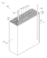
- FIG. 1 illustrates a perspective view of an electrode assembly according to an embodiment of the present invention
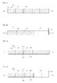
- FIGS. 2A and 2B illustrate a first electrode of the electrode assembly according to an embodiment of the present invention
- FIGS. 3A and 3B illustrate a first electrode of an electrode assembly according to an embodiment of the present invention
- FIGS. 4A and 4B illustrate a second electrode of an electrode assembly according to an embodiment of the present invention
- FIGS. 5A and 5B illustrate a second electrode of an electrode assembly according to an embodiment of the present invention
- FIG. 6 illustrates the electrode assembly of FIG. 1 , before it is wound into a jelly-roll
- FIG. 7 illustrates a cross-sectional view taken along the line A-A' of FIG. 1 ;
- FIG. 8 illustrates a view of a secondary battery having an electrode assembly according to another embodiment of the present invention.
- FIG. 9 illustrates a view of a secondary battery having an electrode assembly according to another embodiment of the present invention.
- FIG. 1 illustrates a perspective view of an electrode assembly according to an embodiment of the present invention
- FIGS. 2A and 2B illustrate a first electrode of the electrode assembly according to an embodiment of the present invention
- FIG. 2A shows a first side surface of the first electrode and FIG. 2B shows a second side surface of the first electrode
- FIGS. 3A and 3B illustrate a first electrode of an electrode assembly according to an embodiment of the present invention
- FIG. 3A shows a first side surface of the first electrode and FIG. 3B shows a second side surface of the first electrode
- FIGS. 4A and 4B illustrate a second electrode of an electrode assembly according to an embodiment of the present invention
- FIG. 4A shows a first side surface of the second electrode and FIG.
- FIGS. 5A and 5B illustrate a second electrode of an electrode assembly according to an embodiment of the present invention (in further detail, FIG. 5A shows a first side surface of the second electrode and FIG. 5B shows a second side surface of the second electrode), FIG. 6 illustrates the electrode assembly of FIG. 1 , before it is wound into a jelly-roll, and FIG. 7 illustrates a cross-sectional view taken along the line A-A' of FIG. 1 .
- an electrode assembly 100 of an embodiment of the present invention includes a first electrode 110, a second electrode 120, and a separator 130.
- the first electrode 110 is provided in the form of a longitudinal strip shape.
- the first electrode 110 includes a first side surface 111 (see FIG. 2A ) and a second side surface 112 (see FIG. 2B ) opposite to the first side surface 111.
- First active material coated portions 113 and 114 formed of a first active material are respectively formed on the first side surface 111 and the second side surface 112 of the first electrode 110.
- the first electrode 110 is rolled up in a jelly-roll.
- a roll-starting end 115 an end that is initially rolled up when the first electrode 110 is being rolled up
- a roll-finishing end 116 an end that is finally rolled up when the first electrode 110 is being rolled up.
- a non-coated portion 117 is formed on the roll-finishing end 116 of the first electrode 110. That is, the non-coated portion 117 is formed on a region of the first side surface 111 of the roll-finishing end 116 of the first electrode 110.
- the non-coated portion 117 is formed on a region extending from the roll-finishing end 116 toward the roll-starting end 115 of the first electrode 110 by a preselected or predetermined length.
- the region for the non-coated portion 117 is lengthened to enclose at least three surfaces of the electrode assembly 100, the at least three surfaces including a front surface, a left surface and a rear surface of the electrode assembly 100 in view point of FIG. 1 .
- the region for the non-coated portion 117 may be lengthened to enclose at most four surfaces of the electrode assembly 100, the at most four surfaces including a front surface, a left surface, a right surface or a rear surface of the electrode assembly 100 in view point of FIG. 1 .
- This is to reduce or minimize a region of the first active material coated portion 113 of the first electrode 110 by removing an unnecessary region of the first active material coated portion 113, thereby reducing or minimizing a volume of the electrode assembly 100. That is, this is to reduce or minimize a volume of the electrode assembly for a given capacity of the electrode assembly 100.
- the electrode assembly 100 is rolled up in a cylinder shape and then is shaped in a prismatic shape by pressing the outer circumference of the rolled-up electrode assembly 100.
- the four surfaces are defined by the outer circumference of the prismatic electrode assembly 100 (in FIGS. 2A and 2B , the four surfaces are divided by dotted-lines on the first side surface and the second side surface of the first electrode 110.
- the dotted-lines define boundary lines between the circumferential surfaces).
- the non-coated portion 117 is formed to define at least three surfaces or at most four surfaces of the outer circumference of the prismatic electrode assembly 100.
- the location of the non-coated portion 117 on the region of the roll-finishing end 116 of the first electrode 110 depends on the arrangement of the first electrode 110 with respect to the second electrode 120. That is, the electrode assembly 100 is designed to charge and discharge energy at an area between the first and second electrodes 110 and 120, which have opposite polarities to each other and between which the separator 130 is disposed. When the first and second electrodes 110 and 120 are rolled up together, as shown in FIGS. 1 and 7 , the non-coated portion 117 does not directly face the second electrode 120.
- the first active material coated portion 113 is located at a region corresponding to the non-coated portion 117, the first active material coated portion 113 located on the region corresponding to the non-coated portion 117 does not function to charge and discharge the electrode assembly and thus the region corresponding to the non-coated portion 117 does not require an active material coating.
- the non-coated portion 117 may be located on a region of the roll-finishing end 116, which does not directly face the second electrode 120 with the separator 130 interposed therebetween.
- the first active material coated portion 114 may be formed along the entire length of the second side surface 112 of the first electrode 110, which is opposite to the first side surface 111 of the first electrode 110. That is, since the second side surface 112 of the first electrode 110 faces the second electrode 120 along its entire length with the separator 130 interposed therebetween, the first active material coated portion 113 is formed along the entire length of the second side surface 112.
- the first electrode 110 may be a positive electrode and the second electrode 120 may be a negative electrode.
- the first electrode 110 may be the negative electrode and the second electrode 120 may be the positive electrode.
- the following will describe a case where the first electrode 110 is the positive electrode and the second electrode 120 is the negative electrode.
- a first electrode 110a shown in FIGS. 3A and 3B , is equivalent to the first electrode 110 of the above-mentioned embodiment, except that the first active material coated portions 113 and 114 are not located on upper and lower portions 118a and 118b that are two edge portions of the first electrode 110a.
- Upper and lower portions 118a and 118b do not include the roll-starting and roll-finishing ends 115 and 116 among four edge portions of the first electrode 110a, and define upper and lower non-coated portions 119a and 119b.
- the first electrode 110a shown in FIGS. 3A and 3B has both of the upper non-coated portion 119a and the lower non-coated portion 119b. However, if necessary, the first electrode 110a may have only one of the upper non-coated portion 119a and the lower non-coated portion 119b.
- the electrode assembly 100 may include a first electrode tab 140 that is electrically and physically connected to the first electrode 110 and extends out of the electrode assembly 100.
- the first electrode tab 140 may be located on the non-coated portion 117 of the first electrode (110 of FIGS. 2A and 2B or 110a of FIGS. 3A and 3B ). That is, the first electrode tab 140 may be located on the first side surface 111 of the roll-finishing end 116 of the first electrode 110 or 110a. Therefore, since the first electrode tab 140 is located on the roll-finishing end 116 of the first electrode 110 or 110a, which is finally rolled up, the first electrode tab 140 is located on an outer circumference of the prismatic electrode assembly 100.
- At least one first electrode tab 140 may be located on the upper non-coated portion 119a or the lower non-coated portion 119b of the first electrode 110a. In this case, the first electrode tab 140 may be located at a central portion of the electrode assembly 100 and/or at the outer circumference portion.
- the coupling of the first electrode 110 with the first electrode tab 140 may be performed by resistance-welding, spot-welding, or laser-welding. However, the coupling may be performed by other coupling methods known to those skilled in the art.
- the second electrode 120 is provided in the form of a longitudinal strip shape.
- the second electrode 120 includes a first side surface 121 (see FIG. 4A ) and a second side surface 122 (see FIG. 4B ) opposite to the first side surface 121.
- Second active material coated portions 123 and 124 are respectively located on the first side surface 121 and the second side surface 122.
- the second electrode 120 is rolled up in a jelly-roll.
- an end that is initially rolled up when the second electrode 120 is being rolled up will be referred to as a roll-starting end 125 and an end that is finally rolled up when the second electrode 120 is being rolled up will be referred to as a roll-finishing end 126.
- a non-coated portion 127 is formed on a region of the second side surface 122 of the roll-staring end 125 of the second electrode 120.
- the non-coated portion 127 is formed on a region extending from the roll-starting end 125 toward the roll-finishing end 126 of the second electrode 120.
- the non-coated portion 127 is lengthened to enclose at least three surfaces of the electrode assembly 100.
- the non-coated portion 127 may be lengthened to enclose at most four surfaces of the electrode assembly 100. This is to reduce or minimize a region of the second active material coated portion 124 of the second electrode 120 by removing an unnecessary region of the second active material coated portion 124, thereby reducing or minimizing a volume of the electrode assembly 100. That is, this is to reduce or minimize a volume for a given capacity of the electrode assembly 100.
- the electrode assembly 100 is rolled up in a cylinder shape and then is shaped in a prismatic shape by pressing the outer circumference of the rolled-up electrode assembly 100.
- the four surfaces are defined by the interior circumference of the prismatic electrode assembly 100 (in FIGS. 4A and 4B , the four surfaces are divided by dotted-lines on the first side surface and the second side surface of the second electrode 120.
- the dotted-lines define boundary lines between the interior circumferential surfaces).
- the non-coated portion 127 defines at least three surfaces or at most four surfaces of the interior circumference of the prismatic electrode assembly 100.
- the location of the non-coated portion 127 on the region of the roll-starting end 125 of the second electrode 120 may depend on the arrangement of the second electrode with respect to the first electrode 110. That is, the electrode assembly 100 is designed to charge and discharge energy at an area between the first and second electrodes 110 and 120, which have polarities opposite to each other and between which the separator 130 is located. When the first and second electrodes 110 and 120 are rolled up together, as shown in FIGS. 1 and 7 , the non-coated portion 127 does not face the first electrode 110.
- the second active material coated portion 124 is located at a region corresponding to the non-coated portion 127, the second active material coated portion 124 located on the region corresponding to the non-coated portion 127 does not function to charge and discharge the energy and thus the region corresponding to the non-coated portion 127 does not require an active material coating.
- the non-coated portion 127 may be located on the region of the roll-starting end 125, which does not face the first electrode 110 with the separator 130 interposed therebetween.
- the second active material coated portion 123 may be formed on the entire length of the first side surface 121 of the second electrode 120. That is, since the first side surface 121 of the second electrode 120 entirely faces the first electrode 110 with the separator 130 interposed therebetween, the second active material coated portion 123 is formed on the entire length of the first side surface 121.
- a second electrode 120a shown in FIGS. 5A and 5B as another embodiment is equal to the second electrode 120 of the above-mentioned embodiment except that the second active material coated portions 123 and 124 are not located on upper and lower portions 128a and 128b that are two edge portions except for the roll-starting and roll-finishing ends 125 and 126 among four edge portions of the second electrode 120a to define upper and lower non-coated portions 129a and 129b.
- the second electrode 120a shown in FIGS. 5A and 5B has both of the upper non-coated portion 129a and the lower non-coated portion 129b. However, if necessary, the second electrode 120a may have only one of the upper non-coated portion 129a and the lower non-coated portion 129b.
- the electrode assembly 100 may include a second electrode tab 150 that is electrically and physically connected to the second electrode 120 and extends out of the electrode assembly 100.
- the second electrode tab 150 may be located on the non-coated portion 127 of the second electrode (120 of FIG. 4A and 4B or 120a of FIGS. 5A and 5B ). That is, the second electrode tab 150 may be located on the second side surface 122 of the roll-starting end 125 of the second electrode 120 or 120a. Therefore, since the second electrode tab 150 is located on the roll-starting end 125 of the second electrode 120 or 120a, which is initially rolled up, the second electrode tab 150 is located on a central portion of the electrode assembly 100.
- At least one second electrode tab 150 may be located on a portion of the upper non-coated portion 129a or the lower non-coated portion 129b of the second electrode 120a. In this case, the second electrode tab 150 may be located at the outer circumferential portion of the electrode assembly 100 as well as the central portion.
- the coupling of the second electrode 120 with the second electrode tab 150 may be performed by resistance-welding, spot-welding, or laser-welding. However the coupling may be performed by other coupling methods.
- the second electrode 120 has a length that is greater than that of the first electrode 110.
- the separator 130 is located between the first and second electrodes 110 and 120 to insulate the first and second electrodes 110 and 120 from each other.
- the electrode assembly 100 of the embodiments is provided in the form of a jelly-roll, at least two separators 130 are necessary. That is, as shown in FIG. 6 , one of the separators 130 may be located between the first and second electrodes 110 and 120 and the other of the separators 130 may be located on the second side surface of the second electrode 120.
- the electrode assembly 100 is rolled up (e.g. in a clockwise motion) starting from the roll-starting ends 115 and 125 of the first and second electrodes 110 and 120. Based on the above described motion and the arrangement of the roll-starting end 125 of the second electrode 120, the other separator 130 is located on the second side surface of the second electrode 120.
- the separators 130 have lengths that are greater than the first electrode 110 and equal to or greater than that of the second electrode 120.
- a method of manufacturing the electrode assembly 100 according to an embodiment of the present invention is described below. As shown in FIG. 6 , the first electrode (110 of FIGS. 2A and 2B or 110a of FIGS. 3A and 3B ), the second electrode (120 of FIGS. 4A and 4B or 120a of FIGS. 5A and 5B ), and the two separators 130 are prepared.
- the first electrode 110 or 110a, the second electrode 120 or 120a, and the separators 130 are aligned.
- the second electrode 120 has a length greater than that of the first electrode 110 and the first and second electrodes 110 and 120 are respectively positive and negative electrodes
- the first electrode 110 or 110a, the second electrode 120 or 120a, and the separators 130 are aligned such that the roll-starting end 125 of the second electrode 120 extends further than the first roll-starting end 115 of the first electrode 110 by a first length (refer to "162" in FIG. 6 ).
- the roll-finishing end 126 of the second electrode 120 extends further than the roll-finishing end 116 of the first electrode 110 by a second length (refer to "164" in FIG. 6 ).
- the first electrode 110, the second electrode 120, and the separators 130 are rolled up in a cylindrical shape based on the roll-starting ends 115 and 125 of the first and second electrodes 110 and 120.
- the cylindrical shape based on the roll-starting end 125 of the second electrode 120 may then be configured in a prismatic shape by pressing the outer circumference of the cylindrical electrode assembly 100.
- FIG. 8 shows a secondary battery having an electrode assembly according to an embodiment of the present invention.
- a secondary battery 1000 of an embodiment of the present invention includes an electrode assembly 1100.
- the electrode assembly 110 may be the electrode assembly 100 of any of FIGS. 1 to 7 .
- the electrode assembly 1100 includes first and second electrode tabs 1110 and 1120.
- the first and second electrode tabs 1110 and 1120 may be respectively the first and second electrode tabs 140 and 150 of FIGS. 1 to 7 , for example.
- the secondary battery 1000 includes a pouch 1200 for receiving the electrode assembly 1100 and a protection circuit module 1300.
- the pouch 1200 includes a main body 1210 and a cover 1220.
- the main body 1210 includes a receiving portion 1212 for receiving the electrode assembly 1100 and a sealing portion 1214 extending from an inlet of the receiving portion 1212.
- the cover 1220 extends from a peripheral portion of the sealing portion 1214 of the main body 1210.
- the cover 1220 fully covers the receiving portion 1212 of the main body 1210 and is sealed with the sealing portion 1214 of the main body 1210.
- the cover 1220 includes a receiving cover region 1222 corresponding to the receiving portion 1212 of the main body 1210 and a sealing portion 1224 corresponding to the sealing portion 1214 of the main body 1210.
- the cover 1220 covers the receiving portion 1212 and the sealing portion 1214 of the main body 1210 is sealed with the sealing portion 1224 of the cover 1220 through a bonding method such as a thermal-bonding.
- the first and second electrode tabs 1110 and 1120 extending from the electrode assembly 1100 are exposed to an external side.
- the first and second electrode tabs 1110 and 1120 are connected to the protection circuit module 1300.
- the protection circuit module 1300 functions to control not only the charging/discharging of the electrode assembly 1100 but also the operation of the secondary battery 1000. Meanwhile, the protection circuit module 1300 includes a control device 1310 such as an integrated circuit device, a secondary protection device 1320 for preventing current from excessively flowing in the secondary battery 1000, and an external terminal 1330 connecting the secondary battery 1000 to an external device.
- a control device 1310 such as an integrated circuit device
- a secondary protection device 1320 for preventing current from excessively flowing in the secondary battery 1000
- an external terminal 1330 connecting the secondary battery 1000 to an external device.
- FIG. 9 shows a secondary battery having an electrode assembly according to an embodiment of the present invention.
- a secondary battery 2000 of this embodiment includes an electrode assembly 2100.
- the electrode assembly 2100 may be the electrode assembly 100 of FIGS. 1 to 7 .
- the electrode assembly 2100 is received in a can 2200 having an opening.
- the electrode assembly 2100 includes first and second electrode tabs 2110 and 2120.
- the first and second electrode tabs 2110 and 2120 may be the first and second electrode tabs 140 and 150 of FIGS. 1 to 7 .
- An insulation case 2300 is inserted into the can 2200, which receives the electrode assembly 2100, through the opening thereof.
- the insulation case 2300 prevents or substantially prevents the electrode assembly 2100 from moving in the can 2200 and insulates a cap plate 2400, which will be described later, and the electrode assembly 2100 from each other.
- the insulation case 2300 is provided with first and second through holes 2310 and 2320 through which the first and second electrode tabs 2110 and 2120 pass, respectively.
- the insulation case 2300 is further provided with an electrolyte injection hole 2330 for injection of electrolyte.
- the cap plate 2400 covers the opening of the can 2200 receiving the electrode assembly 2100, thereby sealing the can 2200.
- An electrode terminal 2410 is provided at a portion (e.g. a predetermined portion) of the cap plate 2400.
- the electrode terminal 2410 is insulated from a plate terminal 2420 that is the other portion of the cap plate 2400.
- the cap plate 2400 is provided with an electrolyte injection hole 2430 for injecting the electrolyte. After the electrolyte is injected, the electrolyte injection hole 2430 is plugged by a plug 2440.
- the electrode terminal 2410 is electrically connected to one of the first and second electrode tabs 2110 and 2120 of the electrode assembly 1100.
- the plate terminal 2420 is electrically connected to the other one of the first and second electrode tabs 2110 and 2120.
- the secondary battery 2000 includes a protection circuit module 2500 for controlling the charging/discharging and operation of the secondary battery 2000.
- the protection circuit module 2500 includes a control device 2510, such as an integrated circuit device, and an external terminal 2520 connecting (e.g. electrically connecting) the secondary battery 2000 to an external device.
- a control device 2510 such as an integrated circuit device
- an external terminal 2520 connecting (e.g. electrically connecting) the secondary battery 2000 to an external device.
- the protection circuit module 2500 is electrically connected to the electrode terminal 2410 and the plate terminal 2420.
- a secondary protective device 2530 for preventing current from excessively flowing in the secondary battery 2000, may be provided between the protection circuit module 2500 and the electrode terminal 2410.
- the secondary protective device 2530 includes a first terminal lead 2532 connected to the electrode terminal 2410, a second terminal lead 2534 connected to the protection circuit module 2500, and a positive temperature coefficient (PTC) device 2536 between the first and second terminal leads 2532 and 2534.
- PTC positive temperature coefficient
- the protection circuit module 2500 is electrically connected to the plate terminal 2420.
- the electrical connection between the protection circuit module 2500 and the plate terminal 2420 is realized by a connecting member 2540.
- the connecting member 2540 is connected (e.g. electrically connected) to the protection circuit module 2500 by a method such as soldering and is connected to the plate terminal 2420 by a method such as soldering, laser welding, resistance welding, or by a coupling member such as a bolt.
Landscapes
- Chemical & Material Sciences (AREA)
- Chemical Kinetics & Catalysis (AREA)
- Electrochemistry (AREA)
- General Chemical & Material Sciences (AREA)
- Engineering & Computer Science (AREA)
- Manufacturing & Machinery (AREA)
- Microelectronics & Electronic Packaging (AREA)
- Secondary Cells (AREA)
- Connection Of Batteries Or Terminals (AREA)
- Sealing Battery Cases Or Jackets (AREA)
Abstract
Description
- The present invention relates to an electrode assembly, a method of manufacturing the electrode assembly, and a secondary battery including the electrode assembly.
- As the electronics industry, communications and computer industries have been rapidly growing more advanced, portable electronic devices have increasingly propagated. Secondary batteries are mainly used as power sources for these portable electronic devices.
- A secondary battery includes an electrode assembly that substantially charges and discharges electrical energy.
- Since the properties and performance of a secondary battery are influenced by the electrode assembly, various types of research and development are being actively carried out on electrode assemblies.
- An aspect of an embodiment according to the present invention provides an electrode assembly having an electrode having a non-coated portion.
- Another aspect of the present invention provides an electrode assembly in which the volume of the electrode assembly is reduced without reducing the capacity.
- Still another aspect of the present invention provides a method of manufacturing the electrode assembly.
- Still yet another aspect of the present invention provides a secondary battery having the electrode assembly.
- According to at least one embodiment of the present invention, an electrode assembly includes: a first electrode coated with a first active material; a second electrode coated with a second active material; and a separator located between the first and second electrodes, the separator being for insulating the first electrode from the second electrode, wherein: the first and second electrodes and the separator are wound into a jelly-roll; at least one of the first and second electrodes includes a non-coated portion where an active material is not coated on a roll-starting end or a roll-finishing end of the at least one of the first and second electrodes; the non-coated portion is located at a region of a first side surface or a second side surface of the at least one of the first and second electrodes; and the region having the non-coated portion does not face an electrode having a different polarity from the at least one of the first and second electrodes with the separator interposed therebetween.
- According to another embodiment of the present invention, a secondary battery includes: an electrode assembly; a case for receiving the electrode assembly; and a protection circuit module to which positive and negative tabs of the electrode assembly are electrically connected, wherein the electrode assembly includes: a first electrode coated with a first active material; a second electrode coated with a second active material; and a separator located between the first and second electrodes for insulating the first electrode from the second electrode, wherein the first and second electrodes and the separator are wound into a jelly-roll, wherein at least one of the first and second electrodes includes a non-coated portion where an active material is not coated on a portion of a roll-starting end or a roll-finishing end, and wherein the non-coated portion is located at a region of a first side surface or a second side surface of the at least one of the first and second electrodes, the region not facing an electrode having a different polarity from the at least one of the first and second electrodes with the separator interposed therebetween.
- The first electrode may be a positive electrode and the second electrode may be a negative electrode.
- The non-coated portion may be located at a region of the roll-finishing end on the first side surface of the first electrode.
- The electrode assembly may further include a first electrode tab that is electrically and physically connected to the non-coated portion and extends from the electrode assembly.
- The first electrode tab may be located at an outer circumference of the electrode assembly.
- The non-coated portion is located at a region of the roll-starting end on the second side surface of the second electrode.
- The electrode assembly may further include a second electrode tab that is physically electrically connected to the non-coated portion and extends from the electrode assembly.
- The second electrode tab may be located at a central portion of the electrode assembly.
- Each of the first and second electrodes may include a first active material coated portion coated with the first active material or a second active material coated portion coated with the second active material on the first side surface or the second side surface except for the non-coated portion.
- The first active material coated portion or the second active material coated portion may exclude a region of at least one of an upper portion or a lower portion that define two edge portions of the first or second electrodes, except for the roll-starting end and the roll-finishing end of the first and second electrodes.
- The electrode assembly may have a prismatic shape, and the non-coated portion may have a length spanning at least three surfaces of the electrode assembly.
- The electrode assembly may have a prismatic shape, and the non-coated portion may have a length that is equal to or less than a length spanning four surfaces of the electrode assembly.
- The separator may have a length that is greater than the length of the first electrode and equal to or greater than the length of the second electrode.
- The case may be a pouch, wherein the pouch includes a main body having a receiving portion for receiving the electrode assembly; and a cover for covering the main body.
- The case may be a prismatic can and the secondary battery may further include a cap assembly, wherein the cap assembly includes a cap plate sealing an opening of the prismatic can; an electrode terminal insulated from the cap plate and passing through the cap plate; a conductive plate electrically connected to the electrode terminal; and an insulation plate for insulating the conductive plate from the cap plate.
- According to still another embodiment, a method of manufacturing an electrode assembly includes: providing first and second electrodes and a separator; and forming the electrode assembly by rolling up the first and second electrodes and the separator based on roll-starting ends of the first and second electrodes, wherein at least one of the first and second electrodes includes a non-coated portion on a portion of a first side surface or a second side surface of the roll-starting end or the roll-finishing end, and wherein the non-coated portion is located at a region of the first side surface or the second side surface of the at least one electrode, and the region having the non-coated portion does not face an electrode having a different polarity from the at least one electrode with the separator interposed therebetween.
- The second electrode may have a length that is greater than the length of the first electrode.
- The first electrode and the second electrode may be arranged such that the roll-starting end of the second electrode may extend further than the roll-starting end of the first electrode and the roll-finishing end of the second electrode may extend further than the roll-finishing end of the first electrode.
- The accompanying drawings are included to provide a further understanding of the present disclosure. The accompanying drawings, together with the specification, illustrate exemplary embodiments of the present disclosure and, together with the description, serve to explain principles of the present disclosure. In the drawings:
-
FIG. 1 illustrates a perspective view of an electrode assembly according to an embodiment of the present invention; -
FIGS. 2A and 2B illustrate a first electrode of the electrode assembly according to an embodiment of the present invention; -
FIGS. 3A and 3B illustrate a first electrode of an electrode assembly according to an embodiment of the present invention; -
FIGS. 4A and 4B illustrate a second electrode of an electrode assembly according to an embodiment of the present invention; -
FIGS. 5A and 5B illustrate a second electrode of an electrode assembly according to an embodiment of the present invention; -
FIG. 6 illustrates the electrode assembly ofFIG. 1 , before it is wound into a jelly-roll; -
FIG. 7 illustrates a cross-sectional view taken along the line A-A' ofFIG. 1 ; -
FIG. 8 illustrates a view of a secondary battery having an electrode assembly according to another embodiment of the present invention; and -
FIG. 9 illustrates a view of a secondary battery having an electrode assembly according to another embodiment of the present invention. - In the following detailed description, only certain exemplary embodiments of the present invention are shown and described, by way of illustration. Like reference numerals designate like elements throughout the specification.
-
FIG. 1 illustrates a perspective view of an electrode assembly according to an embodiment of the present invention,FIGS. 2A and 2B illustrate a first electrode of the electrode assembly according to an embodiment of the present invention (in further detail,FIG. 2A shows a first side surface of the first electrode andFIG. 2B shows a second side surface of the first electrode),FIGS. 3A and 3B illustrate a first electrode of an electrode assembly according to an embodiment of the present invention (in further detail,FIG. 3A shows a first side surface of the first electrode andFIG. 3B shows a second side surface of the first electrode),FIGS. 4A and 4B illustrate a second electrode of an electrode assembly according to an embodiment of the present invention (in further detail,FIG. 4A shows a first side surface of the second electrode andFIG. 4B shows a second side surface of the second electrode),FIGS. 5A and 5B illustrate a second electrode of an electrode assembly according to an embodiment of the present invention (in further detail,FIG. 5A shows a first side surface of the second electrode andFIG. 5B shows a second side surface of the second electrode),FIG. 6 illustrates the electrode assembly ofFIG. 1 , before it is wound into a jelly-roll, andFIG. 7 illustrates a cross-sectional view taken along the line A-A' ofFIG. 1 . - Referring to
FIGS. 1 to 7 , anelectrode assembly 100 of an embodiment of the present invention includes afirst electrode 110, asecond electrode 120, and aseparator 130. - As shown in
FIGS. 2A, 2B , andFIG. 6 , thefirst electrode 110 is provided in the form of a longitudinal strip shape. - The
first electrode 110 includes a first side surface 111 (seeFIG. 2A ) and a second side surface 112 (seeFIG. 2B ) opposite to thefirst side surface 111. First active material coatedportions first side surface 111 and thesecond side surface 112 of thefirst electrode 110. - At this point, the
first electrode 110 is rolled up in a jelly-roll. Among longitudinal opposite ends of thefirst electrode 110, an end that is initially rolled up when thefirst electrode 110 is being rolled up will be referred to as a roll-startingend 115 and an end that is finally rolled up when thefirst electrode 110 is being rolled up will be referred to as a roll-finishingend 116. - A
non-coated portion 117 is formed on the roll-finishingend 116 of thefirst electrode 110. That is, thenon-coated portion 117 is formed on a region of thefirst side surface 111 of the roll-finishingend 116 of thefirst electrode 110. - The
non-coated portion 117 is formed on a region extending from the roll-finishingend 116 toward the roll-startingend 115 of thefirst electrode 110 by a preselected or predetermined length. - The region for the
non-coated portion 117 is lengthened to enclose at least three surfaces of theelectrode assembly 100, the at least three surfaces including a front surface, a left surface and a rear surface of theelectrode assembly 100 in view point ofFIG. 1 . The region for thenon-coated portion 117 may be lengthened to enclose at most four surfaces of theelectrode assembly 100, the at most four surfaces including a front surface, a left surface, a right surface or a rear surface of theelectrode assembly 100 in view point ofFIG. 1 . This is to reduce or minimize a region of the first active material coatedportion 113 of thefirst electrode 110 by removing an unnecessary region of the first active material coatedportion 113, thereby reducing or minimizing a volume of theelectrode assembly 100. That is, this is to reduce or minimize a volume of the electrode assembly for a given capacity of theelectrode assembly 100. - In more detail, as shown in
FIG. 1 , theelectrode assembly 100 is rolled up in a cylinder shape and then is shaped in a prismatic shape by pressing the outer circumference of the rolled-upelectrode assembly 100. At this point, the four surfaces are defined by the outer circumference of the prismatic electrode assembly 100 (inFIGS. 2A and 2B , the four surfaces are divided by dotted-lines on the first side surface and the second side surface of thefirst electrode 110. At this point, the dotted-lines define boundary lines between the circumferential surfaces). Namely, thenon-coated portion 117 is formed to define at least three surfaces or at most four surfaces of the outer circumference of theprismatic electrode assembly 100. - The location of the
non-coated portion 117 on the region of the roll-finishingend 116 of thefirst electrode 110 depends on the arrangement of thefirst electrode 110 with respect to thesecond electrode 120. That is, theelectrode assembly 100 is designed to charge and discharge energy at an area between the first andsecond electrodes separator 130 is disposed. When the first andsecond electrodes FIGS. 1 and7 , thenon-coated portion 117 does not directly face thesecond electrode 120. Therefore, even though the first active material coatedportion 113 is located at a region corresponding to thenon-coated portion 117, the first active material coatedportion 113 located on the region corresponding to thenon-coated portion 117 does not function to charge and discharge the electrode assembly and thus the region corresponding to thenon-coated portion 117 does not require an active material coating. - Therefore, the
non-coated portion 117 may be located on a region of the roll-finishingend 116, which does not directly face thesecond electrode 120 with theseparator 130 interposed therebetween. - Meanwhile, the first active material coated
portion 114 may be formed along the entire length of thesecond side surface 112 of thefirst electrode 110, which is opposite to thefirst side surface 111 of thefirst electrode 110. That is, since thesecond side surface 112 of thefirst electrode 110 faces thesecond electrode 120 along its entire length with theseparator 130 interposed therebetween, the first active material coatedportion 113 is formed along the entire length of thesecond side surface 112. - In one embodiment, the
first electrode 110 may be a positive electrode and thesecond electrode 120 may be a negative electrode. Alternatively, thefirst electrode 110 may be the negative electrode and thesecond electrode 120 may be the positive electrode. For simplicity, the following will describe a case where thefirst electrode 110 is the positive electrode and thesecond electrode 120 is the negative electrode. - In one embodiment, a
first electrode 110a, shown inFIGS. 3A and 3B , is equivalent to thefirst electrode 110 of the above-mentioned embodiment, except that the first active material coatedportions lower portions first electrode 110a. Upper andlower portions first electrode 110a, and define upper and lowernon-coated portions - At this point, the
first electrode 110a shown inFIGS. 3A and 3B has both of the uppernon-coated portion 119a and the lowernon-coated portion 119b. However, if necessary, thefirst electrode 110a may have only one of the uppernon-coated portion 119a and the lowernon-coated portion 119b. - The
electrode assembly 100 may include afirst electrode tab 140 that is electrically and physically connected to thefirst electrode 110 and extends out of theelectrode assembly 100. - The
first electrode tab 140 may be located on thenon-coated portion 117 of the first electrode (110 ofFIGS. 2A and 2B or 110a ofFIGS. 3A and 3B ). That is, thefirst electrode tab 140 may be located on thefirst side surface 111 of the roll-finishingend 116 of thefirst electrode first electrode tab 140 is located on the roll-finishingend 116 of thefirst electrode first electrode tab 140 is located on an outer circumference of theprismatic electrode assembly 100. - Although not shown in the drawings, at least one
first electrode tab 140 may be located on the uppernon-coated portion 119a or the lowernon-coated portion 119b of thefirst electrode 110a. In this case, thefirst electrode tab 140 may be located at a central portion of theelectrode assembly 100 and/or at the outer circumference portion. - The coupling of the
first electrode 110 with thefirst electrode tab 140 may be performed by resistance-welding, spot-welding, or laser-welding. However, the coupling may be performed by other coupling methods known to those skilled in the art. - As shown in
FIGS. 4A, 4B , andFIG. 6 , thesecond electrode 120 is provided in the form of a longitudinal strip shape. - The
second electrode 120 includes a first side surface 121 (seeFIG. 4A ) and a second side surface 122 (seeFIG. 4B ) opposite to thefirst side surface 121. Second active material coatedportions first side surface 121 and thesecond side surface 122. - At this point, the
second electrode 120 is rolled up in a jelly-roll. Among longitudinal opposite ends of thesecond electrode 120, an end that is initially rolled up when thesecond electrode 120 is being rolled up will be referred to as a roll-startingend 125 and an end that is finally rolled up when thesecond electrode 120 is being rolled up will be referred to as a roll-finishingend 126. - A
non-coated portion 127 is formed on a region of thesecond side surface 122 of the roll-staringend 125 of thesecond electrode 120. - The
non-coated portion 127 is formed on a region extending from the roll-startingend 125 toward the roll-finishingend 126 of thesecond electrode 120. - The
non-coated portion 127 is lengthened to enclose at least three surfaces of theelectrode assembly 100. Thenon-coated portion 127 may be lengthened to enclose at most four surfaces of theelectrode assembly 100. This is to reduce or minimize a region of the second active material coatedportion 124 of thesecond electrode 120 by removing an unnecessary region of the second active material coatedportion 124, thereby reducing or minimizing a volume of theelectrode assembly 100. That is, this is to reduce or minimize a volume for a given capacity of theelectrode assembly 100. - In more detail, as shown in
FIG. 1 , theelectrode assembly 100 is rolled up in a cylinder shape and then is shaped in a prismatic shape by pressing the outer circumference of the rolled-upelectrode assembly 100. At this point, the four surfaces are defined by the interior circumference of the prismatic electrode assembly 100 (inFIGS. 4A and 4B , the four surfaces are divided by dotted-lines on the first side surface and the second side surface of thesecond electrode 120. At this point, the dotted-lines define boundary lines between the interior circumferential surfaces). Namely, thenon-coated portion 127 defines at least three surfaces or at most four surfaces of the interior circumference of theprismatic electrode assembly 100. - The location of the
non-coated portion 127 on the region of the roll-startingend 125 of thesecond electrode 120 may depend on the arrangement of the second electrode with respect to thefirst electrode 110. That is, theelectrode assembly 100 is designed to charge and discharge energy at an area between the first andsecond electrodes separator 130 is located. When the first andsecond electrodes FIGS. 1 and7 , thenon-coated portion 127 does not face thefirst electrode 110. Therefore, even though the second active material coatedportion 124 is located at a region corresponding to thenon-coated portion 127, the second active material coatedportion 124 located on the region corresponding to thenon-coated portion 127 does not function to charge and discharge the energy and thus the region corresponding to thenon-coated portion 127 does not require an active material coating. - Therefore, the
non-coated portion 127 may be located on the region of the roll-startingend 125, which does not face thefirst electrode 110 with theseparator 130 interposed therebetween. - Meanwhile, the second active material coated
portion 123 may be formed on the entire length of thefirst side surface 121 of thesecond electrode 120. That is, since thefirst side surface 121 of thesecond electrode 120 entirely faces thefirst electrode 110 with theseparator 130 interposed therebetween, the second active material coatedportion 123 is formed on the entire length of thefirst side surface 121. - A
second electrode 120a shown inFIGS. 5A and 5B as another embodiment is equal to thesecond electrode 120 of the above-mentioned embodiment except that the second active material coatedportions lower portions second electrode 120a to define upper and lowernon-coated portions - At this point, the
second electrode 120a shown inFIGS. 5A and 5B has both of the uppernon-coated portion 129a and the lowernon-coated portion 129b. However, if necessary, thesecond electrode 120a may have only one of the uppernon-coated portion 129a and the lowernon-coated portion 129b. - The
electrode assembly 100 may include asecond electrode tab 150 that is electrically and physically connected to thesecond electrode 120 and extends out of theelectrode assembly 100. - The
second electrode tab 150 may be located on thenon-coated portion 127 of the second electrode (120 ofFIG. 4A and 4B or 120a ofFIGS. 5A and 5B ). That is, thesecond electrode tab 150 may be located on thesecond side surface 122 of the roll-startingend 125 of thesecond electrode second electrode tab 150 is located on the roll-startingend 125 of thesecond electrode second electrode tab 150 is located on a central portion of theelectrode assembly 100. - Although not shown in the drawings, at least one
second electrode tab 150 may be located on a portion of the uppernon-coated portion 129a or the lowernon-coated portion 129b of thesecond electrode 120a. In this case, thesecond electrode tab 150 may be located at the outer circumferential portion of theelectrode assembly 100 as well as the central portion. - The coupling of the
second electrode 120 with thesecond electrode tab 150 may be performed by resistance-welding, spot-welding, or laser-welding. However the coupling may be performed by other coupling methods. - The
second electrode 120 has a length that is greater than that of thefirst electrode 110. - The
separator 130 is located between the first andsecond electrodes second electrodes - Since the
electrode assembly 100 of the embodiments is provided in the form of a jelly-roll, at least twoseparators 130 are necessary. That is, as shown inFIG. 6 , one of theseparators 130 may be located between the first andsecond electrodes separators 130 may be located on the second side surface of thesecond electrode 120. - In one embodiment, the
electrode assembly 100 is rolled up (e.g. in a clockwise motion) starting from the roll-starting ends 115 and 125 of the first andsecond electrodes end 125 of thesecond electrode 120, theother separator 130 is located on the second side surface of thesecond electrode 120. - The
separators 130 have lengths that are greater than thefirst electrode 110 and equal to or greater than that of thesecond electrode 120. - A method of manufacturing the
electrode assembly 100 according to an embodiment of the present invention is described below. As shown inFIG. 6 , the first electrode (110 ofFIGS. 2A and 2B or 110a ofFIGS. 3A and 3B ), the second electrode (120 ofFIGS. 4A and 4B or 120a ofFIGS. 5A and 5B ), and the twoseparators 130 are prepared. - The
first electrode second electrode separators 130 are aligned. - At this point, since the
second electrode 120 has a length greater than that of thefirst electrode 110 and the first andsecond electrodes first electrode second electrode separators 130 are aligned such that the roll-startingend 125 of thesecond electrode 120 extends further than the first roll-startingend 115 of thefirst electrode 110 by a first length (refer to "162" inFIG. 6 ). In one embodiment, the roll-finishingend 126 of thesecond electrode 120 extends further than the roll-finishingend 116 of thefirst electrode 110 by a second length (refer to "164" inFIG. 6 ). - In one embodiment, the
first electrode 110, thesecond electrode 120, and theseparators 130 are rolled up in a cylindrical shape based on the roll-starting ends 115 and 125 of the first andsecond electrodes end 125 of thesecond electrode 120 may then be configured in a prismatic shape by pressing the outer circumference of thecylindrical electrode assembly 100. -
FIG. 8 shows a secondary battery having an electrode assembly according to an embodiment of the present invention. - Referring to
FIG. 8 , asecondary battery 1000 of an embodiment of the present invention includes anelectrode assembly 1100. Here, theelectrode assembly 110 may be theelectrode assembly 100 of any ofFIGS. 1 to 7 . Theelectrode assembly 1100 includes first andsecond electrode tabs second electrode tabs second electrode tabs FIGS. 1 to 7 , for example. - The
secondary battery 1000 includes apouch 1200 for receiving theelectrode assembly 1100 and aprotection circuit module 1300. - The
pouch 1200 includes a main body 1210 and a cover 1220. - The main body 1210 includes a receiving
portion 1212 for receiving theelectrode assembly 1100 and a sealingportion 1214 extending from an inlet of the receivingportion 1212. - The cover 1220 extends from a peripheral portion of the sealing
portion 1214 of the main body 1210. The cover 1220 fully covers the receivingportion 1212 of the main body 1210 and is sealed with the sealingportion 1214 of the main body 1210. To achieve this, the cover 1220 includes a receivingcover region 1222 corresponding to the receivingportion 1212 of the main body 1210 and a sealingportion 1224 corresponding to the sealingportion 1214 of the main body 1210. - Accordingly, after the
electrode assembly 1100 is received in the receivingportion 1212 of the main body 1210, the cover 1220 covers the receivingportion 1212 and the sealingportion 1214 of the main body 1210 is sealed with the sealingportion 1224 of the cover 1220 through a bonding method such as a thermal-bonding. - After sealing the
pouch 1200, the first andsecond electrode tabs electrode assembly 1100 are exposed to an external side. Here, the first andsecond electrode tabs protection circuit module 1300. - The
protection circuit module 1300 functions to control not only the charging/discharging of theelectrode assembly 1100 but also the operation of thesecondary battery 1000. Meanwhile, theprotection circuit module 1300 includes a control device 1310 such as an integrated circuit device, asecondary protection device 1320 for preventing current from excessively flowing in thesecondary battery 1000, and anexternal terminal 1330 connecting thesecondary battery 1000 to an external device. -
FIG. 9 shows a secondary battery having an electrode assembly according to an embodiment of the present invention. - Referring to
FIG. 9 , asecondary battery 2000 of this embodiment includes anelectrode assembly 2100. - The
electrode assembly 2100 may be theelectrode assembly 100 ofFIGS. 1 to 7 . - The
electrode assembly 2100 is received in a can 2200 having an opening. - The
electrode assembly 2100 includes first andsecond electrode tabs second electrode tabs second electrode tabs FIGS. 1 to 7 . - An
insulation case 2300 is inserted into thecan 2200, which receives theelectrode assembly 2100, through the opening thereof. - The
insulation case 2300 prevents or substantially prevents theelectrode assembly 2100 from moving in thecan 2200 and insulates acap plate 2400, which will be described later, and theelectrode assembly 2100 from each other. - The
insulation case 2300 is provided with first and second throughholes second electrode tabs insulation case 2300 is further provided with anelectrolyte injection hole 2330 for injection of electrolyte. - The
cap plate 2400 covers the opening of thecan 2200 receiving theelectrode assembly 2100, thereby sealing thecan 2200. - An
electrode terminal 2410 is provided at a portion (e.g. a predetermined portion) of thecap plate 2400. Theelectrode terminal 2410 is insulated from aplate terminal 2420 that is the other portion of thecap plate 2400. Thecap plate 2400 is provided with anelectrolyte injection hole 2430 for injecting the electrolyte. After the electrolyte is injected, theelectrolyte injection hole 2430 is plugged by aplug 2440. - The
electrode terminal 2410 is electrically connected to one of the first andsecond electrode tabs electrode assembly 1100. Theplate terminal 2420 is electrically connected to the other one of the first andsecond electrode tabs - The
secondary battery 2000 includes aprotection circuit module 2500 for controlling the charging/discharging and operation of thesecondary battery 2000. - The
protection circuit module 2500 includes acontrol device 2510, such as an integrated circuit device, and anexternal terminal 2520 connecting (e.g. electrically connecting) thesecondary battery 2000 to an external device. - The
protection circuit module 2500 is electrically connected to theelectrode terminal 2410 and theplate terminal 2420. - At this point, a secondary
protective device 2530, for preventing current from excessively flowing in thesecondary battery 2000, may be provided between theprotection circuit module 2500 and theelectrode terminal 2410. - The secondary
protective device 2530 includes afirst terminal lead 2532 connected to theelectrode terminal 2410, asecond terminal lead 2534 connected to theprotection circuit module 2500, and a positive temperature coefficient (PTC)device 2536 between the first and second terminal leads 2532 and 2534. - Meanwhile, the
protection circuit module 2500 is electrically connected to theplate terminal 2420. - The electrical connection between the
protection circuit module 2500 and theplate terminal 2420 is realized by a connectingmember 2540. The connectingmember 2540 is connected (e.g. electrically connected) to theprotection circuit module 2500 by a method such as soldering and is connected to theplate terminal 2420 by a method such as soldering, laser welding, resistance welding, or by a coupling member such as a bolt.
Claims (17)
- An electrode assembly (100) comprising:a first electrode (110) coated with a first active material;a second electrode (120) coated with a second active material; anda separator (130) located between the first and second electrodes (110, 120), whereinthe first and second electrodes (110, 120) and the separator (130) are wound into a jelly-roll, characterized in thatat least one of the first and second electrodes (110, 120) comprises a non-coated portion (117, 127) where an active material is not coated on a roll-starting end (115, 125) or a roll-finishing end (116, 126) of the at least one of the first and second electrodes (110, 120);the non-coated portion (117, 127) is located at a region of a first side surface (111, 121) or a second side surface (112, 122) of the at least one of the first and second electrodes (110, 120); andthe region having the non-coated portion (117, 127) does not face an electrode having a different polarity from the at least one of the first and second electrodes (110, 120) with the separator (130) interposed therebetween.
- The electrode assembly as claimed in claim 1, wherein the first electrode (110) is a positive electrode and the second electrode (120) is a negative electrode.
- The electrode assembly as claimed in claim 1 or 2, wherein the non-coated portion (117, 127) is located at a region of the roll-finishing end (116, 126) on the first side surface (111) of the first electrode (110).
- The electrode assembly as claimed in claim 3, further comprising a first electrode tab (140) that is electrically and physically connected to the non-coated portion (117) and extends from the electrode assembly (100).
- The electrode assembly as claimed in claim 4, wherein the first electrode tab (140) is located at an outer circumference of the electrode assembly (100).
- The electrode assembly as claimed in claim 3, further comprising a second electrode tab (150) that is physically and electrically connected to the non-coated portion (127) and extends from the electrode assembly (100).
- The electrode assembly as claimed in claim 6, wherein the second electrode tab (150) is located at a central portion of the electrode assembly (100).
- The electrode assembly as claimed in claim 1, wherein the non-coated portion (127) is located at a region of the roll-starting end (125) on the second side surface (122) of the second electrode (120).
- The electrode assembly as claimed in claim 1, wherein each of the first and second electrodes (110, 120) comprises a first active material coated portion (113, 123) coated with the first active material or a second active material coated portion (114, 124) coated with the second active material on the first side surface (111, 121) or the second side surface (112, 122) except for the non-coated portion (117, 127).
- The electrode assembly as claimed in claim 9, wherein at least one of the first active material coated portion (113, 123) or the second active material coated portion (114, 124) does not include a region of at least one of an upper portion or a lower portion that define two edge portions of the first or second electrodes (110, 120), except for the roll-starting end (115, 125) and the roll-finishing end (116, 126) of the first and second electrodes (110, 120).
- The electrode assembly as claimed in any of the preceding claims, wherein the electrode assembly (100) has a prismatic shape, and the non-coated portion (117, 127) has a length spanning at least three surfaces of the electrode assembly (100) or equal to or less than a length spanning four surfaces of the electrode assembly (100).
- The electrode assembly as claimed in any of the preceding claims, wherein the separator (130) has a length that is greater than the length of the first electrode (110) and equal to or greater than the length of the second electrode (120).
- A method of manufacturing an electrode assembly (100) comprising first and second electrodes (110, 120) and a separator (130), the method comprising:rolling up the first and second electrodes (110, 120) and the separator (130) based on roll-starting ends (115, 125) of the first and second electrodes (110, 120) to form the electrode assembly (100),wherein at least one of the first and second electrodes (110, 120) comprises a non-coated portion (117, 127) on a first side surface (111, 121) or a second side surface (112, 122) of the roll-starting end (115, 125) or a roll-finishing end (116, 126), andwherein the non-coated portion (117, 127) is located at a region of the first side surface (111, 121) or the second side surface (112, 122) of the at least one of the first and second electrodes (110, 120), and the region having the non-coated portion (117, 127) does not face an electrode having a different polarity from the at least one of the first and second electrodes (110, 120) with the separator (130) interposed therebetween.
- The method as claimed in claim 13, wherein the first electrode and the second electrode (110, 120) are arranged such that the roll-starting end (125) of the second electrode (120) extends further than the roll-starting end (115) of the first electrode (110) and the roll-finishing end (126) of the second electrode (120) extends further than the roll-finishing end (116) of the first electrode (110).
- A secondary battery comprising:an electrode assembly according to any of claims 1 through 12;a case for receiving the electrode assembly; anda protection circuit module to which positive and negative tabs of the electrode assembly are electrically connected.
- The secondary battery as claimed in claim 15, wherein the case is a pouch,
wherein the pouch comprises:a main body having a receiving portion for receiving the electrode assembly; anda cover for covering the main body. - The secondary battery as claimed in claim 16, wherein the case is a prismatic can, and the secondary battery further comprises a cap assembly comprising:a cap plate sealing an opening of the prismatic can;an electrode terminal insulated from the cap plate and passing through the cap plate;a conductive plate electrically connected to the electrode terminal; and an insulation plate for insulating the conductive plate from the cap plate.
Applications Claiming Priority (1)
| Application Number | Priority Date | Filing Date | Title |
|---|---|---|---|
| KR1020100007038A KR101156331B1 (en) | 2010-01-26 | 2010-01-26 | Electrode assembly, method for fabricating the electrode assembly and secondary battery including the electrode assembly |
Publications (1)
| Publication Number | Publication Date |
|---|---|
| EP2348562A1 true EP2348562A1 (en) | 2011-07-27 |
Family
ID=43983373
Family Applications (1)
| Application Number | Title | Priority Date | Filing Date |
|---|---|---|---|
| EP11150192A Withdrawn EP2348562A1 (en) | 2010-01-26 | 2011-01-05 | Electrode assembly, method of manufacturing electrode assembly, and secondary battery including electrode assembly |
Country Status (5)
| Country | Link |
|---|---|
| US (1) | US8450002B2 (en) |
| EP (1) | EP2348562A1 (en) |
| JP (1) | JP5330318B2 (en) |
| KR (1) | KR101156331B1 (en) |
| CN (1) | CN102136563A (en) |
Cited By (1)
| Publication number | Priority date | Publication date | Assignee | Title |
|---|---|---|---|---|
| EP2736102A1 (en) * | 2012-11-23 | 2014-05-28 | Samsung SDI Co., Ltd. | Electrode assembly and rechargeable battery having the same |
Families Citing this family (5)
| Publication number | Priority date | Publication date | Assignee | Title |
|---|---|---|---|---|
| KR101199161B1 (en) | 2011-02-11 | 2012-11-12 | 삼성에스디아이 주식회사 | Electrode assembly and secondary battery using the same |
| EP2999042B1 (en) * | 2013-11-12 | 2019-01-09 | LG Chem, Ltd. | Jelly-roll type electrode assembly and secondary battery having same |
| JP6227614B2 (en) * | 2015-10-16 | 2017-11-08 | ファナック株式会社 | Screen creation device having application screen creation support function |
| KR102654626B1 (en) * | 2016-10-27 | 2024-04-04 | 삼성에스디아이 주식회사 | Secondary battery |
| JP7494949B2 (en) * | 2021-01-29 | 2024-06-04 | 株式会社村田製作所 | Secondary batteries, electronic devices and power tools |
Citations (6)
| Publication number | Priority date | Publication date | Assignee | Title |
|---|---|---|---|---|
| JP2001216997A (en) * | 2000-02-04 | 2001-08-10 | Matsushita Electric Ind Co Ltd | Spiral electrode group for battery and battery using the same |
| JP2003338276A (en) * | 2002-05-20 | 2003-11-28 | Matsushita Electric Ind Co Ltd | Lithium ion secondary battery |
| US20050277022A1 (en) * | 2004-06-14 | 2005-12-15 | Matsushita Electric Industrial Co., Ltd. | Electrochemical element |
| EP1724857A1 (en) * | 2005-05-18 | 2006-11-22 | Samsung SDI Co., Ltd. | Jelly-roll type electrode assembly and lithium secondary battery with the same |
| WO2009096703A1 (en) * | 2008-01-28 | 2009-08-06 | Lg Chem. Ltd. | Battery having enhanced electrical insulation capability |
| WO2009128605A2 (en) * | 2008-04-17 | 2009-10-22 | Lg Chem. Ltd. | Battery having enhanced electrical insulation capability |
Family Cites Families (8)
| Publication number | Priority date | Publication date | Assignee | Title |
|---|---|---|---|---|
| JP3580161B2 (en) * | 1998-12-15 | 2004-10-20 | トヨタ自動車株式会社 | Power generation element and method of manufacturing the same |
| JP2001266927A (en) * | 2000-03-23 | 2001-09-28 | Nec Mobile Energy Kk | Wound battery |
| KR100490548B1 (en) * | 2002-12-27 | 2005-05-17 | 삼성에스디아이 주식회사 | Secondary battery with jelly-roll type electrode assembly |
| KR100601555B1 (en) * | 2004-06-14 | 2006-07-19 | 삼성에스디아이 주식회사 | Wound electrode assembly and lithium secondary battery using same |
| KR100601504B1 (en) * | 2004-06-28 | 2006-07-19 | 삼성에스디아이 주식회사 | Electrode assembly and lithium ion secondary battery using same |
| US20060093922A1 (en) * | 2004-09-22 | 2006-05-04 | Kim Cheon S | Composite material tape for lithium secondary battery and lithium secondary battery using the same |
| JP4635978B2 (en) * | 2006-08-02 | 2011-02-23 | ソニー株式会社 | Negative electrode and secondary battery |
| JP2009211857A (en) * | 2008-03-03 | 2009-09-17 | Sony Corp | Battery |
-
2010
- 2010-01-26 KR KR1020100007038A patent/KR101156331B1/en active Active
- 2010-06-04 JP JP2010128976A patent/JP5330318B2/en active Active
- 2010-08-16 US US12/856,902 patent/US8450002B2/en active Active
- 2010-11-16 CN CN2010105496715A patent/CN102136563A/en active Pending
-
2011
- 2011-01-05 EP EP11150192A patent/EP2348562A1/en not_active Withdrawn
Patent Citations (6)
| Publication number | Priority date | Publication date | Assignee | Title |
|---|---|---|---|---|
| JP2001216997A (en) * | 2000-02-04 | 2001-08-10 | Matsushita Electric Ind Co Ltd | Spiral electrode group for battery and battery using the same |
| JP2003338276A (en) * | 2002-05-20 | 2003-11-28 | Matsushita Electric Ind Co Ltd | Lithium ion secondary battery |
| US20050277022A1 (en) * | 2004-06-14 | 2005-12-15 | Matsushita Electric Industrial Co., Ltd. | Electrochemical element |
| EP1724857A1 (en) * | 2005-05-18 | 2006-11-22 | Samsung SDI Co., Ltd. | Jelly-roll type electrode assembly and lithium secondary battery with the same |
| WO2009096703A1 (en) * | 2008-01-28 | 2009-08-06 | Lg Chem. Ltd. | Battery having enhanced electrical insulation capability |
| WO2009128605A2 (en) * | 2008-04-17 | 2009-10-22 | Lg Chem. Ltd. | Battery having enhanced electrical insulation capability |
Cited By (2)
| Publication number | Priority date | Publication date | Assignee | Title |
|---|---|---|---|---|
| EP2736102A1 (en) * | 2012-11-23 | 2014-05-28 | Samsung SDI Co., Ltd. | Electrode assembly and rechargeable battery having the same |
| US9263761B2 (en) | 2012-11-23 | 2016-02-16 | Samsung Sdi Co., Ltd. | Electrode assembly and rechargeable battery having the same |
Also Published As
| Publication number | Publication date |
|---|---|
| US8450002B2 (en) | 2013-05-28 |
| KR20110087559A (en) | 2011-08-03 |
| US20110183170A1 (en) | 2011-07-28 |
| JP2011154989A (en) | 2011-08-11 |
| CN102136563A (en) | 2011-07-27 |
| KR101156331B1 (en) | 2012-06-13 |
| JP5330318B2 (en) | 2013-10-30 |
Similar Documents
| Publication | Publication Date | Title |
|---|---|---|
| CN101271985B (en) | Rechargeable battery and manufacturing method thereof | |
| KR101036070B1 (en) | Secondary battery | |
| EP2395576B1 (en) | Rechargeable battery comprising a fuse | |
| JP4276102B2 (en) | Pouch-type lithium secondary battery and manufacturing method thereof | |
| US8501341B2 (en) | Rechargeable battery | |
| KR101130294B1 (en) | Rechargeable Battery | |
| US9023498B2 (en) | Rechargeable battery | |
| EP2348558B1 (en) | Rechargeable battery | |
| EP3046160B1 (en) | Rechargeable battery and pack of the same | |
| EP2357685B1 (en) | Rechargeable battery | |
| US9142823B2 (en) | Rechargeable battery and module of the same | |
| EP2642561B1 (en) | Rechargeable battery | |
| EP2597705B1 (en) | Rechargeable battery | |
| US20170018794A1 (en) | Rechargeable battery and rechargeable battery module using the same | |
| US8450002B2 (en) | Electrode assembly including electrode having non-coated portion, method of manufacturing the same, and secondary battery including the same | |
| US9559341B2 (en) | Rechargeable battery having a vent unit at a joint in a cap plate | |
| KR100930473B1 (en) | Battery-free battery pack using interference fit rivets | |
| KR100590009B1 (en) | Secondary Battery and Electrode Assembly Used in the Same | |
| KR20180044089A (en) | Rechargeable battery | |
| KR20040042373A (en) | Cylindrical secondary battery | |
| US20140004388A1 (en) | Battery pack and case | |
| KR20180001884A (en) | Rechargeable battery | |
| EP3001481B1 (en) | Rechargeable battery | |
| CN109923692B (en) | Battery pack |
Legal Events
| Date | Code | Title | Description |
|---|---|---|---|
| PUAI | Public reference made under article 153(3) epc to a published international application that has entered the european phase |
Free format text: ORIGINAL CODE: 0009012 |
|
| 17P | Request for examination filed |
Effective date: 20110105 |
|
| AK | Designated contracting states |
Kind code of ref document: A1 Designated state(s): AL AT BE BG CH CY CZ DE DK EE ES FI FR GB GR HR HU IE IS IT LI LT LU LV MC MK MT NL NO PL PT RO RS SE SI SK SM TR |
|
| AX | Request for extension of the european patent |
Extension state: BA ME |
|
| 17Q | First examination report despatched |
Effective date: 20120629 |
|
| RAP1 | Party data changed (applicant data changed or rights of an application transferred) |
Owner name: SAMSUNG SDI CO., LTD. Owner name: ROBERT BOSCH GMBH |
|
| GRAP | Despatch of communication of intention to grant a patent |
Free format text: ORIGINAL CODE: EPIDOSNIGR1 |
|
| RIC1 | Information provided on ipc code assigned before grant |
Ipc: H01M 2/02 20060101ALN20160217BHEP Ipc: H01M 10/0587 20100101ALN20160217BHEP Ipc: H01M 2/16 20060101AFI20160217BHEP Ipc: H01M 10/04 20060101ALI20160217BHEP |
|
| INTG | Intention to grant announced |
Effective date: 20160316 |
|
| RIN1 | Information on inventor provided before grant (corrected) |
Inventor name: KWAK, YOONTAI |
|
| STAA | Information on the status of an ep patent application or granted ep patent |
Free format text: STATUS: THE APPLICATION IS DEEMED TO BE WITHDRAWN |
|
| 18D | Application deemed to be withdrawn |
Effective date: 20160727 |