EP2348412A1 - Dual field instrument - Google Patents
Dual field instrument Download PDFInfo
- Publication number
- EP2348412A1 EP2348412A1 EP10195153A EP10195153A EP2348412A1 EP 2348412 A1 EP2348412 A1 EP 2348412A1 EP 10195153 A EP10195153 A EP 10195153A EP 10195153 A EP10195153 A EP 10195153A EP 2348412 A1 EP2348412 A1 EP 2348412A1
- Authority
- EP
- European Patent Office
- Prior art keywords
- code
- unit
- bus
- microprocessor
- data
- Prior art date
- Legal status (The legal status is an assumption and is not a legal conclusion. Google has not performed a legal analysis and makes no representation as to the accuracy of the status listed.)
- Granted
Links
Images


Classifications
-
- G—PHYSICS
- G06—COMPUTING OR CALCULATING; COUNTING
- G06F—ELECTRIC DIGITAL DATA PROCESSING
- G06F11/00—Error detection; Error correction; Monitoring
- G06F11/07—Responding to the occurrence of a fault, e.g. fault tolerance
- G06F11/16—Error detection or correction of the data by redundancy in hardware
- G06F11/1629—Error detection by comparing the output of redundant processing systems
- G06F11/1641—Error detection by comparing the output of redundant processing systems where the comparison is not performed by the redundant processing components
- G06F11/1645—Error detection by comparing the output of redundant processing systems where the comparison is not performed by the redundant processing components and the comparison itself uses redundant hardware
-
- G—PHYSICS
- G06—COMPUTING OR CALCULATING; COUNTING
- G06F—ELECTRIC DIGITAL DATA PROCESSING
- G06F11/00—Error detection; Error correction; Monitoring
- G06F11/07—Responding to the occurrence of a fault, e.g. fault tolerance
- G06F11/16—Error detection or correction of the data by redundancy in hardware
- G06F11/1629—Error detection by comparing the output of redundant processing systems
- G06F11/1633—Error detection by comparing the output of redundant processing systems using mutual exchange of the output between the redundant processing components
-
- G—PHYSICS
- G06—COMPUTING OR CALCULATING; COUNTING
- G06F—ELECTRIC DIGITAL DATA PROCESSING
- G06F2201/00—Indexing scheme relating to error detection, to error correction, and to monitoring
- G06F2201/83—Indexing scheme relating to error detection, to error correction, and to monitoring the solution involving signatures
Definitions
- the present invention relates to a dual field instrument that includes a first microprocessor and a second microprocessor performing the same operation process and detects abnormality by collating the operation of the first microprocessor with the operation of the second microprocessor.
- Japanese Unexamined Patent Application, First Publication No. 2005-309913 discloses a transmitter that includes an operation system of performing an operation based on a sensor measurement value.
- the transmitter performs an inverse-operation on the result of the operation system to regenerate the sensor measurement value.
- the transmitter collates the sensor measurement value regenerated by the inverse-operation system with the original sensor measurement value to detect abnormalities. If both of the sensor measurement values do not coincide, then the transmitter can detect an abnormal state.
- the inverse-operation system cannot regenerate the sensor measurement value. For example, if one operation result is operated based on a plurality of sensor measurement values in the operation system, then the inverse-operation system cannot be configured.
- Japanese Unexamined Patent Application, First Publication No. 2006-209523 discloses an information processor that doubly performs the same operation and outputs one operation result to the outside.
- the information processor two microprocessors perform the same operation process. The operation results at an arbitrary step or the attached information of the operation are exchanged between the two microprocessors to be collated. If they do not coincide, the information processor determines an abnormal state and outputs an abnormality annunciation signal to the outside.
- a dual field instrument may include a first microprocessor that includes a first address bus and a first data bus, the first microprocessor performing a first operation process, a second microprocessor that includes a second address bus and a second data bus, the second microprocessor performing a second operation process, the second operation process being the same with the first operation process, a first code analysis unit that compresses and encodes histories of data on at least one of the first address bus and the first data bus to generate a first code by a first process, a second code analysis unit that compresses and encodes histories of data on at least one of the second address bus and the second data bus to generate a second code by a second process, and a first collating unit that collates the first code with the second code so as to determine whether or not the first code corresponds with the second code.
- the first process may be the same with the second process.
- the first process may be performed when data on the first address bus is within a specified address area.
- the second process may be performed when data on the second address bus is within the specified address area.
- the specified address area may be an address area of a memory that stores a program defining at least one of the first operation process and the second operation process.
- Each of the first code analysis unit and the second code analysis unit may include a linear feedback shift register.
- the dual field instrument may further include a signal output unit. If the first collating unit determines that the first code corresponds with the second code, then the signal output unit may output one of a first operation result of the first operation process and a second operation result of the second operation process. If the first collating unit determines that the first code does not corresponds with the second code, then the signal output unit may output an abnormality annunciation signal.
- the dual field instrument may further include a first information exchange unit that receives the first code from the first code analysis unit, the first information exchange unit receiving the second code from a second information exchange unit, the first information exchange unit outputting the first code and the second code to the first collating unit, the second information exchange unit that receives the second code from the second code analysis unit, the second information exchange unit receiving the first code from the first information exchange unit, the first information exchange unit outputting the first code and the second code to a second collating unit, and the second collating unit that receives the first code and the second code from the second information exchange unit, the second collating unit collating the first code with the second code so as to determine whether or not the first code corresponds with the second code.
- the first collating unit may receive the first code and the second code from the first information exchange unit.
- a dual field instrument may include a first microprocessor that receives a sensor measurement value, the first microprocessor performing a first operation process to generate a first output value, the first microprocessor outputting a first code, a second microprocessor that receives the sensor measurement value, the second microprocessor performing a second operation process to generate a second output value, the second microprocessor outputting a second code, the second operation process being the same with the first operation process, a first information exchange unit that receives the first code from the first microprocessor, the first information exchange unit receiving the second code from a second information exchange unit, the first information exchange unit outputting the first code and the second code to a first collating unit, the second information exchange unit that receives the second code from the second microprocessor, the second information exchange unit receiving the first code from the first information exchange unit, the second information exchange unit outputting the first code and the second code to a second collating unit, the first collating unit that receives the first code and the second code from the first information exchange unit, the second information exchange unit outputting the
- the signal output unit may output a first discrepancy detection signal. If the second collating unit determines that the first code does not correspond with the second code, then the signal output unit may output a second discrepancy detection signal.
- the dual field instrument may further include a standardized signal output unit that receives the first output value from the first microprocessor, the standardized signal output unit receiving the second output value from the second microprocessor, the standardized signal output unit receiving the first discrepancy detection signal from the first collating unit, the standardized signal output unit receiving the second discrepancy detection signal from the second collating unit, the standardized signal output unit outputting a standardized signal current.
- the standardized signal output unit may output 4-20 mA current as the standardized signal current, based on at least one of the first output value of the first microprocessor and the second output value from the second microprocessor.
- the standardized signal output unit may output an predetermined abnormality annunciation current as the standardized signal current.
- the standardized signal output unit may output an predetermined abnormality annunciation current as the standardized signal current.
- the first microprocessor may include a first CPU that performs the first operation process, a first input-output unit that receives the sensor measurement value, the first input-output unit outputting the first output value, a first memory that stores a first program performing the first operation process, a first code analysis unit that outputs the first bus observation code, a first address bus that connects between the first CPU, the first input-output unit, the first memory and the first code analysis unit, and a first data bus that connects between the first CPU, the first input-output unit, the first memory and the first code analysis unit.
- the second microprocessor may include a second CPU that performs the second operation process, a second input-output unit that receives the sensor measurement value, the second input-output unit outputting the second output value, a second memory that stores a second program performing the second operation process, a second code analysis unit that outputs the second bus observation code, a second address bus that connects between the second CPU, the second input-output unit, the second memory and the second code analysis unit, and a second data bus that connects between the second CPU, the second input-output unit, the second memory and the second code analysis unit.
- the first CPU may output a first bus clock.
- the first code analysis unit may receive the first bus clock.
- the second CPU may output a second bus clock.
- the second code analysis unit may receive the second bus clock.
- the first code analysis unit may read first data on the first address bus and the first data bus.
- the first code analysis unit may encode and compress the first data based on the first bus clock to generate the first bus observation code.
- the second code analysis unit may read second data on the second address bus and the second data bus.
- the second code analysis unit may encode and compress the second data based on the second bus clock to generate the second bus observation code.
- the first code analysis unit may output a change history of a data pattern in each of the first address bus and the data address bus as the first bus observation code.
- the second code analysis unit may output a change history of a data pattern in each of the second address bus and the second data bus as the second bus observation code.
- the first bus observation code and the second bus observation code may be codes of serial bit stream.
- the first code analysis unit may encode and compress the first data. If data on the second address bus is within a second specified address area, then the second code analysis unit may encode and compress the second data.
- Each of the first code analysis unit and the second code analysis unit may include a linear feedback shift register.
- the dual field instrument of the present invention can detect abnormalities with high precision and high speed while the burden of the microprocessor is suppressed.
- each history of multiple-bit data on the address bus or the data bus in the two microprocessors is compressed and encoded to generate codes. Then the generated codes are collated. The burden on the microprocessor is suppressed. An abnormality can be detected with high precision and high speed.
- FIG. 1 is a block diagram illustrating a configuration of a dual field instrument in accordance with the first preferred embodiment of the present invention.
- the dual field instrument includes a measurement sensor 3, a first operation unit 10, a second operation unit 20, and a standardized signal output unit 4.
- the measurement sensor 3 outputs a sensor measurement value.
- the first operation unit 10 and the second operation unit 20 perform the same operation based on the sensor measurement value output from the measurement sensor 3.
- the standardized signal output unit 4 outputs a single signal as a standardized signal current based on signals and output values that are output from the first operation unit 10 and the second operation unit 20.
- the measurement sensor 3 includes a sensor unit and a measurement circuit.
- the sensor unit measures physical quantities such as a temperature and a pressure.
- the measurement circuit converts an output signal of the sensor unit to a digital value, and outputs it as the sensor measurement value.
- the first operation unit 10 and the second operation unit 20 have the same configuration.
- the first operation unit 10 includes a first microprocessor 11, a first information exchange unit 12, and a first collating unit 13.
- the first microprocessor 11 receives the sensor measurement value from the measurement sensor 3 and performs the above-mentioned operation to output a bus observation code A to the first information exchange unit 12 and output a first output value to the standardized signal output unit 4.
- the first information exchange unit 12 receives the bus observation code A from the first microprocessor 11 and outputs the bus observation code A to the first collating unit 13 3 and a second information exchange unit 22 in the second operation unit 20. Also, the first information exchange unit 12 receives a bus observation code B from the second information exchange unit 22 and outputs the bus observation code B to the first collating unit 13. That is, the first information exchange unit 12 performs a code exchange.
- the first collating unit 13 receives the bus observation code A and the bus observation code B from the first information exchange unit 12 and collates the bus observation code A with the bus observation code B. If the bus observation code A does not correspond to the bus observation code B, then the first collating unit 13 outputs a first discrepancy detection signal to the standardized signal output unit 4.
- the second operation unit 20 includes a second microprocessor 21, a second information exchange unit 22, and a second collating unit 23.
- the second microprocessor 21 receives the sensor measurement value from the measurement sensor 3 and performs the above-mentioned operation to output a bus observation code B to the second information exchange unit 22 and to output a second output value to the standardized signal output unit 4.
- the second information exchange unit 22 receives the bus observation code B from the second microprocessor 21 and outputs the bus observation code B to the second collating unit 23 and the first information exchange unit 12 in the first operation unit 10. Also, the second information exchange unit 22 receives a bus observation code A from the first information exchange unit 12 and outputs the bus observation code A to the second collating unit 23.
- the second information exchange unit 22 performs the code exchange.
- the second collating unit 23 receives the bus observation code A and the bus observation code B from the second information exchange unit 22 and collates the bus observation code A with the bus observation code B. If the bus observation code A does not correspond to the bus observation code B, then the second collating unit 23 outputs a second discrepancy detection signal to the standardized signal output unit 4.
- FIG. 2 is a block diagram illustrating a configuration of the first microprocessor 11 and the second microprocessor 21.
- the first microprocessor 11 and the second microprocessor 21 have the same configuration.
- the first microprocessor 11 includes a first CPU 11 a, a first input-output unit 11b, a first memory 11c, and a first code analysis unit 11 d.
- the first CPU 11 a, the first input-output unit 11 b, the first memory 11 c, and the first code analysis unit 11 d are connected to each other through an address bus Ba and a data bus Bd.
- the first CPU 11a outputs a bus clock to the first input-output unit 11b, the first memory 11c, and the first code analysis unit 11 d.
- the first input-output unit 11 b controls input and output of data between the first CPU 11 a and outside of the first microprocessor 11.
- the first input-output unit 11 b receives the sensor measurement value from the measurement sensor 3 and outputs the first output value to the standardized signal output unit 4.
- the first CPU 11 a reads and writes data stored in the first memory 11c during the operation.
- the first code analysis unit 11d receives and encodes data on the address bus Ba and the data bus Bd and outputs the bus observation code A to the first information exchange unit 12.
- the second microprocessor 21 includes a second CPU 21 a, a second input-output unit 21 b, a second memory 21 c, and a second code analysis unit 21 d.
- the second CPU 21 a, the second input-output unit 21 b, the second memory 21 c, and the second code analysis unit 21 d are connected each other through an address bus Ba and a data bus Bd.
- the second CPU 21a outputs a bus clock to the second input-output unit 21 b, the second memory 21 c, and the second code analysis unit 21d.
- the second input-output unit 21 b controls input and output of data between the second CPU 21a and outside of the second microprocessor 21.
- the second input-output unit 21 b receives the sensor measurement value from the measurement sensor 3 and outputs the second output value to the standardized signal output unit 4.
- the second CPU 21 a reads and writes data stored in the second memory 21 c during the operation.
- the second code analysis unit 21 d receives and encodes data on the address bus Ba and the data bus Bd and outputs the bus observation code B to the second information exchange unit 22.
- the sensor measurement value from the measurement sensor 3 is input to the first microprocessor 11 and the second microprocessor 21.
- the first microprocessor 11 and the second microprocessor 21 respectively perform the same operation based on the sensor measurement value.
- the first microprocessor 11 outputs the result of the operation as the first output value to the standardized signal output unit 4.
- the second microprocessor 21 outputs the result of the operation as the second output value to the standardized signal output unit 4.
- the first CPU 11 a receives the sensor measurement value through the first input-output unit 11b. Then, the first CPU 11a performs the operation based on the program stored in the first memory 11 c and outputs the result of the operation to the standardized signal output unit 4 through the first input-output unit 11b.
- the first code analysis unit 11d reads data on the address bus Ba and the data bus Bd. Then, the first code analysis unit 1 1d encodes and compresses the data at each bus clock to output as the bus observation code A.
- the second CPU 21 a receives the sensor measurement value through the second input-output unit 21b. Then, the second CPU 21a performs the operation based on the program stored in the second memory 21 c and outputs the result of the operation to the standardized signal output unit 4 through the second input-output unit 21b.
- the second code analysis unit 21d reads data on the address bus Ba and the data bus Bd. Then, the second code analysis unit 21d encodes and compresses the data at each bus clock to output as the bus observation code B.
- the first code analysis unit 11d and the second code analysis unit 21d may have a general configuration having a linear feedback shift register.
- the first code analysis unit 11 d outputs a change history of a data pattern in each bus as the bus observation code A.
- the second code analysis unit 21d outputs a change history of a data pattern in each bus as the bus observation code B.
- the data pattern is a signal pattern of multiple-bits.
- the bus observation code A and the bus observation code B are codes of serial bit stream.
- the history of the data pattern in each bus can be observed without affecting the processes of the first CPU 11 a and the second CPU 21 a.
- Encoding of the data pattern in each bus may be performed by a general method that is disclosed in " Testing by feedback shift register", IEEE Transactions on Computers Vol. C-29, No. 7, pp. 668-673, July 1980 , for example.
- the bus observation code A output from the first code analysis unit 11d is received by the first information exchange unit 12.
- the bus observation code B output from the second code analysis unit 21 d is received by the second information exchange unit 22.
- the bus observation code A and the bus observation code B are exchanged by the first information exchange unit 12 and the second information exchange unit 22 respectively.
- the first information exchange unit 12 synchronizes the bus observation code A with the bus observation code B.
- the second information exchange unit 22 synchronizes the bus observation code B with the bus observation code A.
- the first information exchange unit 12 outputs the synchronized bus observation code A and the synchronized bus observation code B to the first collating unit 13.
- the second information exchange unit 22 outputs the synchronized bus observation code A and the synchronized bus observation code B to the second collating unit 23.
- the first collating unit 13 compares the synchronized bus observation code A with the synchronized bus observation code B to detect discrepancy between the synchronized bus observation code A and the synchronized bus observation code B.
- the second collating unit 23 compares the synchronized bus observation code B with the synchronized bus observation code A to detect discrepancies between the synchronized bus observation code A and the synchronized bus observation code B.
- first collating unit 13 detects discrepancy
- first collating unit 13 outputs the first discrepancy detection signal to the standardized signal output unit 4.
- second collating unit 23 detects a discrepancy
- second collating unit 23 outputs the second discrepancy detection signal to the standardized signal output unit 4.
- the standardized signal output unit 4 If neither the first discrepancy detection signal nor the second discrepancy detection signal is input to the standardized signal output unit 4, then the standardized signal output unit 4 outputs standard 4-20 mA current loop signal as the standardized signal current, based on the first output value from the first microprocessor 11 or the second output value from the second microprocessor 21 or both the first output value and the second output value.
- the standardized signal output unit 4 If at least one of the first discrepancy detection signal and the second discrepancy detection signal is input to the standardized signal output unit 4, then the standardized signal output unit 4 outputs an abnormality annunciation current that is predetermined as the standardized signal current. Thereby, occurrence of abnormality is annunciated.
- two information exchange units and two collating units are disposed. Therefore, an abnormality of the process in the information exchange unit and the collating unit can also be detected.
- the standardized signal output unit 4 may output the abnormality annunciation current.
- the dual field instrument in accordance with the first preferred embodiment of the present invention compresses and encodes histories of CPU buses of two microprocessors that perform the same operation process to generate codes, and collates the codes to determine sequentially whether or not the operation process has abnormality. Therefore, abnormality in the operation process can be detected with high precision and with high speed.
- An additional process of exchanging information or collating the exchanged information need not be added to the program of the operation process. Therefore, the burden on the microprocessor is decreased, and decline of the processing power in the operation process can be avoided.
- Codes generated by the code analysis units are collated. Thereby, the amount of the information to be collated is less than in the case of collating data of the CPU bus directly. Therefore, a reduction in power consumption and cut to the cost of system can be attained.
- the area of collating can be made smaller than in the case of collating the operation result at each operation step. Thereby, the degree of accuracy in detecting abnormalities can be increased.
- the dual field instrument in accordance with the first preferred embodiment of the present invention continuously performs the encoding based on data on the address bus and the data bus of the CPU.
- the information of the bus that is encoded may be limited to a specified address.
- a first program that defines the operation process performed by the two microprocessors and a second program that defines other processes may be separately stored on the memory. That is, the address area storing the first program and the address area storing the second program are separated. Then, only the data in the address area storing the first program may be encoded.
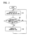
- FIG. 3 is a flowchart illustrating an operation of the first code analysis unit 11d and the second code analysis unit 21 d when only data in a specified address area is encoded.
- the specified address area is the address area storing the first program that defines the operation process performed by the two microprocessors.
- step S 1 of FIG. 3 the first code analysis unit 11 d and the second code analysis unit 21 d respectively acquire data from the address bus and the data bus at a timing based on the bus clock.
- step S2 the first code analysis unit 11d and the second code analysis unit 21 d respectively determine whether or not the acquired data from the address bus is within the specified address area. If the acquired data from the address bus is the specified address, then go to step S3. If the acquired data from the address bus is not the specified address, then return to the step S 1.
- codes are generated by the first code analysis unit 11d and the second code analysis unit 21 d compressing and encoding the acquired data from the address bus and the data bus that is acquired in the step S1, then return to the step S1.
- encoding is performed only when the data acquired from the address bus is within the specified address area. All of the operation process is not necessary to be synchronized. Only the operation process corresponding to the first program needs to be synchronized. Therefore, the process of synchronizing can be performed easily. For example, a first series of process that performs the encoding operation and a second series of process that does not need the encoding operation may be repeated alternately at a constant cycle. Thereby, the phase of the process can be detected easily. The burden in performing the synchronizing process can be decreased.
- the data on the bus that is to be encoded is limited, and two microprocessors may respectively perform different processes except the first program.
- unit is used to describe a component, section or part of a hardware and/or software that is constructed and/or programmed to carry out the desired function.
- Typical examples of the hardware may include, but are not limited to, a device and a circuit.
- the present invention can be applied to any dual field instrument that includes two microprocessors performing the same operation process and detects an abnormality by collating the operation processes of the two microprocessors. Accordingly, the present invention is not to be considered as being limited by the foregoing description, and is only limited by the scope of the claims.
Landscapes
- Engineering & Computer Science (AREA)
- Theoretical Computer Science (AREA)
- Quality & Reliability (AREA)
- Physics & Mathematics (AREA)
- General Engineering & Computer Science (AREA)
- General Physics & Mathematics (AREA)
- Hardware Redundancy (AREA)
- Arrangements For Transmission Of Measured Signals (AREA)
- Testing Or Calibration Of Command Recording Devices (AREA)
- Safety Devices In Control Systems (AREA)
Abstract
Description
- The present invention relates to a dual field instrument that includes a first microprocessor and a second microprocessor performing the same operation process and detects abnormality by collating the operation of the first microprocessor with the operation of the second microprocessor.
- Priority is claimed on Japanese Patent Application No.
2009-285836, filed December 17, 2009 - All patents, patent applications, patent publications, scientific articles, and the like, which will hereinafter be cited or identified in the present application, will hereby be incorporated by reference in their entirety in order to describe more fully the state of the art to which the present invention pertains.
- Japanese Unexamined Patent Application, First Publication No.
2005-309913 - In some cases, the inverse-operation system cannot regenerate the sensor measurement value. For example, if one operation result is operated based on a plurality of sensor measurement values in the operation system, then the inverse-operation system cannot be configured.
- Japanese Unexamined Patent Application, First Publication No.
2006-209523 - To detect various abnormalities and to detect them quickly, the frequency of collating the information exchanged between the two microprocessors needs to be increased. Then, the burden on the microprocessors is increased.
- A dual field instrument may include a first microprocessor that includes a first address bus and a first data bus, the first microprocessor performing a first operation process, a second microprocessor that includes a second address bus and a second data bus, the second microprocessor performing a second operation process, the second operation process being the same with the first operation process, a first code analysis unit that compresses and encodes histories of data on at least one of the first address bus and the first data bus to generate a first code by a first process, a second code analysis unit that compresses and encodes histories of data on at least one of the second address bus and the second data bus to generate a second code by a second process, and a first collating unit that collates the first code with the second code so as to determine whether or not the first code corresponds with the second code.
- The first process may be the same with the second process.
- The first process may be performed when data on the first address bus is within a specified address area. The second process may be performed when data on the second address bus is within the specified address area.
- The specified address area may be an address area of a memory that stores a program defining at least one of the first operation process and the second operation process.
- Each of the first code analysis unit and the second code analysis unit may include a linear feedback shift register.
- The dual field instrument may further include a signal output unit. If the first collating unit determines that the first code corresponds with the second code, then the signal output unit may output one of a first operation result of the first operation process and a second operation result of the second operation process. If the first collating unit determines that the first code does not corresponds with the second code, then the signal output unit may output an abnormality annunciation signal.
- The dual field instrument may further include a first information exchange unit that receives the first code from the first code analysis unit, the first information exchange unit receiving the second code from a second information exchange unit, the first information exchange unit outputting the first code and the second code to the first collating unit, the second information exchange unit that receives the second code from the second code analysis unit, the second information exchange unit receiving the first code from the first information exchange unit, the first information exchange unit outputting the first code and the second code to a second collating unit, and the second collating unit that receives the first code and the second code from the second information exchange unit, the second collating unit collating the first code with the second code so as to determine whether or not the first code corresponds with the second code. The first collating unit may receive the first code and the second code from the first information exchange unit.
- A dual field instrument may include a first microprocessor that receives a sensor measurement value, the first microprocessor performing a first operation process to generate a first output value, the first microprocessor outputting a first code, a second microprocessor that receives the sensor measurement value, the second microprocessor performing a second operation process to generate a second output value, the second microprocessor outputting a second code, the second operation process being the same with the first operation process, a first information exchange unit that receives the first code from the first microprocessor, the first information exchange unit receiving the second code from a second information exchange unit, the first information exchange unit outputting the first code and the second code to a first collating unit, the second information exchange unit that receives the second code from the second microprocessor, the second information exchange unit receiving the first code from the first information exchange unit, the second information exchange unit outputting the first code and the second code to a second collating unit, the first collating unit that receives the first code and the second code from the first information exchange unit, the first collating unit collating the first code with the second code so as to determine whether or not the first code corresponds with the second code, and the second collating unit that receives the first code and the second code from the second information exchange unit, the second collating unit collating the first code with the second code so as to determine whether or not the first code corresponds with the second code.
- If the first collating unit determines that the first code does not correspond with the second code, then the signal output unit may output a first discrepancy detection signal. If the second collating unit determines that the first code does not correspond with the second code, then the signal output unit may output a second discrepancy detection signal.
- The dual field instrument may further include a standardized signal output unit that receives the first output value from the first microprocessor, the standardized signal output unit receiving the second output value from the second microprocessor, the standardized signal output unit receiving the first discrepancy detection signal from the first collating unit, the standardized signal output unit receiving the second discrepancy detection signal from the second collating unit, the standardized signal output unit outputting a standardized signal current.
- If neither the first discrepancy detection signal nor the second discrepancy detection signal is input to the standardized signal output unit, then the standardized signal output unit may output 4-20 mA current as the standardized signal current, based on at least one of the first output value of the first microprocessor and the second output value from the second microprocessor.
- If at least one of the first discrepancy detection signal and the second discrepancy detection signal is input to the standardized signal output unit, then the standardized signal output unit may output an predetermined abnormality annunciation current as the standardized signal current.
- If the first output value from the first microprocessor is different from the second output value from the second microprocessor, then the standardized signal output unit may output an predetermined abnormality annunciation current as the standardized signal current.
- The first microprocessor may include a first CPU that performs the first operation process, a first input-output unit that receives the sensor measurement value, the first input-output unit outputting the first output value, a first memory that stores a first program performing the first operation process, a first code analysis unit that outputs the first bus observation code, a first address bus that connects between the first CPU, the first input-output unit, the first memory and the first code analysis unit, and a first data bus that connects between the first CPU, the first input-output unit, the first memory and the first code analysis unit. The second microprocessor may include a second CPU that performs the second operation process, a second input-output unit that receives the sensor measurement value, the second input-output unit outputting the second output value, a second memory that stores a second program performing the second operation process, a second code analysis unit that outputs the second bus observation code, a second address bus that connects between the second CPU, the second input-output unit, the second memory and the second code analysis unit, and a second data bus that connects between the second CPU, the second input-output unit, the second memory and the second code analysis unit.
- The first CPU may output a first bus clock. The first code analysis unit may receive the first bus clock. The second CPU may output a second bus clock. The second code analysis unit may receive the second bus clock.
- The first code analysis unit may read first data on the first address bus and the first data bus. The first code analysis unit may encode and compress the first data based on the first bus clock to generate the first bus observation code. The second code analysis unit may read second data on the second address bus and the second data bus. The second code analysis unit may encode and compress the second data based on the second bus clock to generate the second bus observation code.
- The first code analysis unit may output a change history of a data pattern in each of the first address bus and the data address bus as the first bus observation code. The second code analysis unit may output a change history of a data pattern in each of the second address bus and the second data bus as the second bus observation code. The first bus observation code and the second bus observation code may be codes of serial bit stream.
- If data on the first address bus is within a first specified address area, then the first code analysis unit may encode and compress the first data. If data on the second address bus is within a second specified address area, then the second code analysis unit may encode and compress the second data.
- Each of the first code analysis unit and the second code analysis unit may include a linear feedback shift register.
- The above features and advantages of the present invention will be more apparent from the following description of certain preferred embodiments taken in conjunction with the accompanying drawings, in which:
-
FIG. 1 is a block diagram illustrating a configuration of a dual field instrument in accordance with a first preferred embodiment of the present invention; -
FIG. 2 is a block diagram illustrating a configuration of the first microprocessor and the second microprocessor ofFIG. 1 ; and -
FIG. 3 is a flowchart illustrating an operation of the first code analysis unit and the second code analysis unit ofFIG. 1 when only data in a specified address area is encoded. - The dual field instrument of the present invention can detect abnormalities with high precision and high speed while the burden of the microprocessor is suppressed.
- In the dual field instrument of the present invention, each history of multiple-bit data on the address bus or the data bus in the two microprocessors is compressed and encoded to generate codes. Then the generated codes are collated. The burden on the microprocessor is suppressed. An abnormality can be detected with high precision and high speed.
- The present invention will be now described herein with reference to illustrative embodiments. Those skilled in the art will recognize that many alternative embodiments can be accomplished using the teaching of the present invention and that the present invention is not limited to the embodiments illustrated herein for explanatory purposes.
- A first preferred embodiment of the present invention will be described.
FIG. 1 is a block diagram illustrating a configuration of a dual field instrument in accordance with the first preferred embodiment of the present invention. - The dual field instrument includes a
measurement sensor 3, afirst operation unit 10, asecond operation unit 20, and a standardizedsignal output unit 4. Themeasurement sensor 3 outputs a sensor measurement value. Thefirst operation unit 10 and thesecond operation unit 20 perform the same operation based on the sensor measurement value output from themeasurement sensor 3. The standardizedsignal output unit 4 outputs a single signal as a standardized signal current based on signals and output values that are output from thefirst operation unit 10 and thesecond operation unit 20. - The
measurement sensor 3 includes a sensor unit and a measurement circuit. The sensor unit measures physical quantities such as a temperature and a pressure. The measurement circuit converts an output signal of the sensor unit to a digital value, and outputs it as the sensor measurement value. - The
first operation unit 10 and thesecond operation unit 20 have the same configuration. - The
first operation unit 10 includes afirst microprocessor 11, a firstinformation exchange unit 12, and afirst collating unit 13. Thefirst microprocessor 11 receives the sensor measurement value from themeasurement sensor 3 and performs the above-mentioned operation to output a bus observation code A to the firstinformation exchange unit 12 and output a first output value to the standardizedsignal output unit 4. The firstinformation exchange unit 12 receives the bus observation code A from thefirst microprocessor 11 and outputs the bus observation code A to thefirst collating unit 13 3 and a secondinformation exchange unit 22 in thesecond operation unit 20. Also, the firstinformation exchange unit 12 receives a bus observation code B from the secondinformation exchange unit 22 and outputs the bus observation code B to thefirst collating unit 13. That is, the firstinformation exchange unit 12 performs a code exchange. Thefirst collating unit 13 receives the bus observation code A and the bus observation code B from the firstinformation exchange unit 12 and collates the bus observation code A with the bus observation code B. If the bus observation code A does not correspond to the bus observation code B, then thefirst collating unit 13 outputs a first discrepancy detection signal to the standardizedsignal output unit 4. - In the same way, the
second operation unit 20 includes asecond microprocessor 21, a secondinformation exchange unit 22, and asecond collating unit 23. Thesecond microprocessor 21 receives the sensor measurement value from themeasurement sensor 3 and performs the above-mentioned operation to output a bus observation code B to the secondinformation exchange unit 22 and to output a second output value to the standardizedsignal output unit 4. The secondinformation exchange unit 22 receives the bus observation code B from thesecond microprocessor 21 and outputs the bus observation code B to thesecond collating unit 23 and the firstinformation exchange unit 12 in thefirst operation unit 10. Also, the secondinformation exchange unit 22 receives a bus observation code A from the firstinformation exchange unit 12 and outputs the bus observation code A to thesecond collating unit 23. That is, the secondinformation exchange unit 22 performs the code exchange. Thesecond collating unit 23 receives the bus observation code A and the bus observation code B from the secondinformation exchange unit 22 and collates the bus observation code A with the bus observation code B. If the bus observation code A does not correspond to the bus observation code B, then thesecond collating unit 23 outputs a second discrepancy detection signal to the standardizedsignal output unit 4. -
FIG. 2 is a block diagram illustrating a configuration of thefirst microprocessor 11 and thesecond microprocessor 21. Thefirst microprocessor 11 and thesecond microprocessor 21 have the same configuration. - The
first microprocessor 11 includes afirst CPU 11 a, a first input-output unit 11b, afirst memory 11c, and a firstcode analysis unit 11 d. Thefirst CPU 11 a, the first input-output unit 11 b, thefirst memory 11 c, and the firstcode analysis unit 11 d are connected to each other through an address bus Ba and a data bus Bd. Thefirst CPU 11a outputs a bus clock to the first input-output unit 11b, thefirst memory 11c, and the firstcode analysis unit 11 d. The first input-output unit 11 b controls input and output of data between thefirst CPU 11 a and outside of thefirst microprocessor 11. The first input-output unit 11 b receives the sensor measurement value from themeasurement sensor 3 and outputs the first output value to the standardizedsignal output unit 4. Thefirst CPU 11 a reads and writes data stored in thefirst memory 11c during the operation. The firstcode analysis unit 11d receives and encodes data on the address bus Ba and the data bus Bd and outputs the bus observation code A to the firstinformation exchange unit 12. - In the same way, the
second microprocessor 21 includes asecond CPU 21 a, a second input-output unit 21 b, asecond memory 21 c, and a secondcode analysis unit 21 d. Thesecond CPU 21 a, the second input-output unit 21 b, thesecond memory 21 c, and the secondcode analysis unit 21 d are connected each other through an address bus Ba and a data bus Bd. Thesecond CPU 21a outputs a bus clock to the second input-output unit 21 b, thesecond memory 21 c, and the secondcode analysis unit 21d. The second input-output unit 21 b controls input and output of data between thesecond CPU 21a and outside of thesecond microprocessor 21. The second input-output unit 21 b receives the sensor measurement value from themeasurement sensor 3 and outputs the second output value to the standardizedsignal output unit 4. Thesecond CPU 21 a reads and writes data stored in thesecond memory 21 c during the operation. The secondcode analysis unit 21 d receives and encodes data on the address bus Ba and the data bus Bd and outputs the bus observation code B to the secondinformation exchange unit 22. - Next, the operation of the dual field instrument in accordance with the first preferred embodiment of the present invention will be described.
- The sensor measurement value from the
measurement sensor 3 is input to thefirst microprocessor 11 and thesecond microprocessor 21. Thefirst microprocessor 11 and thesecond microprocessor 21 respectively perform the same operation based on the sensor measurement value. Thefirst microprocessor 11 outputs the result of the operation as the first output value to the standardizedsignal output unit 4. Thesecond microprocessor 21 outputs the result of the operation as the second output value to the standardizedsignal output unit 4. - The
first CPU 11 a receives the sensor measurement value through the first input-output unit 11b. Then, thefirst CPU 11a performs the operation based on the program stored in thefirst memory 11 c and outputs the result of the operation to the standardizedsignal output unit 4 through the first input-output unit 11b. The firstcode analysis unit 11d reads data on the address bus Ba and the data bus Bd. Then, the firstcode analysis unit 1 1d encodes and compresses the data at each bus clock to output as the bus observation code A. - Similarly, the
second CPU 21 a receives the sensor measurement value through the second input-output unit 21b. Then, thesecond CPU 21a performs the operation based on the program stored in thesecond memory 21 c and outputs the result of the operation to the standardizedsignal output unit 4 through the second input-output unit 21b. The secondcode analysis unit 21d reads data on the address bus Ba and the data bus Bd. Then, the secondcode analysis unit 21d encodes and compresses the data at each bus clock to output as the bus observation code B. - The first
code analysis unit 11d and the secondcode analysis unit 21d may have a general configuration having a linear feedback shift register. The firstcode analysis unit 11 d outputs a change history of a data pattern in each bus as the bus observation code A. Similarly, the secondcode analysis unit 21d outputs a change history of a data pattern in each bus as the bus observation code B. The data pattern is a signal pattern of multiple-bits. The bus observation code A and the bus observation code B are codes of serial bit stream. The history of the data pattern in each bus can be observed without affecting the processes of thefirst CPU 11 a and thesecond CPU 21 a. Encoding of the data pattern in each bus may be performed by a general method that is disclosed in "Testing by feedback shift register", IEEE Transactions on Computers Vol. C-29, No. 7, pp. 668-673, July 1980, for example. - The bus observation code A output from the first
code analysis unit 11d is received by the firstinformation exchange unit 12. The bus observation code B output from the secondcode analysis unit 21 d is received by the secondinformation exchange unit 22. The bus observation code A and the bus observation code B are exchanged by the firstinformation exchange unit 12 and the secondinformation exchange unit 22 respectively. The firstinformation exchange unit 12 synchronizes the bus observation code A with the bus observation code B. The secondinformation exchange unit 22 synchronizes the bus observation code B with the bus observation code A. - The first
information exchange unit 12 outputs the synchronized bus observation code A and the synchronized bus observation code B to thefirst collating unit 13. The secondinformation exchange unit 22 outputs the synchronized bus observation code A and the synchronized bus observation code B to thesecond collating unit 23. - The
first collating unit 13 compares the synchronized bus observation code A with the synchronized bus observation code B to detect discrepancy between the synchronized bus observation code A and the synchronized bus observation code B. Thesecond collating unit 23 compares the synchronized bus observation code B with the synchronized bus observation code A to detect discrepancies between the synchronized bus observation code A and the synchronized bus observation code B. - If the
first collating unit 13 detects discrepancy, then thefirst collating unit 13 outputs the first discrepancy detection signal to the standardizedsignal output unit 4. If thesecond collating unit 23 detects a discrepancy, then thesecond collating unit 23 outputs the second discrepancy detection signal to the standardizedsignal output unit 4. - If neither the first discrepancy detection signal nor the second discrepancy detection signal is input to the standardized
signal output unit 4, then the standardizedsignal output unit 4 outputs standard 4-20 mA current loop signal as the standardized signal current, based on the first output value from thefirst microprocessor 11 or the second output value from thesecond microprocessor 21 or both the first output value and the second output value. - If at least one of the first discrepancy detection signal and the second discrepancy detection signal is input to the standardized
signal output unit 4, then the standardizedsignal output unit 4 outputs an abnormality annunciation current that is predetermined as the standardized signal current. Thereby, occurrence of abnormality is annunciated. In the first preferred embodiment of the present invention, two information exchange units and two collating units are disposed. Therefore, an abnormality of the process in the information exchange unit and the collating unit can also be detected. - When neither the first discrepancy detection signal nor the second discrepancy detection signal is input to the standardized
signal output unit 4, if the first output value from thefirst microprocessor 11 is different from the second output value from thesecond microprocessor 21, then the standardizedsignal output unit 4 may output the abnormality annunciation current. - As described above, the dual field instrument in accordance with the first preferred embodiment of the present invention compresses and encodes histories of CPU buses of two microprocessors that perform the same operation process to generate codes, and collates the codes to determine sequentially whether or not the operation process has abnormality. Therefore, abnormality in the operation process can be detected with high precision and with high speed.
- An additional process of exchanging information or collating the exchanged information need not be added to the program of the operation process. Therefore, the burden on the microprocessor is decreased, and decline of the processing power in the operation process can be avoided.
- Codes generated by the code analysis units are collated. Thereby, the amount of the information to be collated is less than in the case of collating data of the CPU bus directly. Therefore, a reduction in power consumption and cut to the cost of system can be attained.
- The area of collating can be made smaller than in the case of collating the operation result at each operation step. Thereby, the degree of accuracy in detecting abnormalities can be increased.
- The dual field instrument in accordance with the first preferred embodiment of the present invention continuously performs the encoding based on data on the address bus and the data bus of the CPU. The information of the bus that is encoded may be limited to a specified address.
- A first program that defines the operation process performed by the two microprocessors and a second program that defines other processes may be separately stored on the memory. That is, the address area storing the first program and the address area storing the second program are separated. Then, only the data in the address area storing the first program may be encoded.
-
FIG. 3 is a flowchart illustrating an operation of the firstcode analysis unit 11d and the secondcode analysis unit 21 d when only data in a specified address area is encoded. The specified address area is the address area storing the first program that defines the operation process performed by the two microprocessors. - In
step S 1 ofFIG. 3 , the firstcode analysis unit 11 d and the secondcode analysis unit 21 d respectively acquire data from the address bus and the data bus at a timing based on the bus clock. - Next, in step S2, the first
code analysis unit 11d and the secondcode analysis unit 21 d respectively determine whether or not the acquired data from the address bus is within the specified address area. If the acquired data from the address bus is the specified address, then go to step S3. If the acquired data from the address bus is not the specified address, then return to thestep S 1. - In the step S3, codes are generated by the first
code analysis unit 11d and the secondcode analysis unit 21 d compressing and encoding the acquired data from the address bus and the data bus that is acquired in the step S1, then return to the step S1. - As described above, in the process of
FIG. 3 , encoding is performed only when the data acquired from the address bus is within the specified address area. All of the operation process is not necessary to be synchronized. Only the operation process corresponding to the first program needs to be synchronized. Therefore, the process of synchronizing can be performed easily. For example, a first series of process that performs the encoding operation and a second series of process that does not need the encoding operation may be repeated alternately at a constant cycle. Thereby, the phase of the process can be detected easily. The burden in performing the synchronizing process can be decreased. - The data on the bus that is to be encoded is limited, and two microprocessors may respectively perform different processes except the first program.
- As described above, in the dual field instrument of the present invention, histories of multiple-bit data on the address bus and the data bus of the two microprocessors are respectively compressed and encoded to generate codes. Then, the generated codes are collated. Thereby, the burden on the microprocessor is suppressed. An abnormality can be detected with high precision and high speed.
- As used herein, the following directional terms "forward, rearward, above, downward, vertical, horizontal, below, and transverse" as well as any other similar directional terms refer to those directions of an apparatus equipped with the present invention. Accordingly, these terms, as utilized to describe the present invention should be interpreted relative to an apparatus equipped with the present invention.
- The term "configured" is used to describe a component, section or part of a device includes hardware and/or software that is constructed and/or programmed to carry out the desired function.
- Moreover, terms that are expressed as "means-plus function" in the claims should include any structure that can be utilized to carry out the function of that part of the present invention.
- The terms of degree such as "substantially," "about," "nearly", and "approximately" as used herein mean a reasonable amount of deviation of the modified term such that the end result is not significantly changed. Fo r example, these terms can be construed as including a deviation of at least ± 5 percents of the modified term if this deviation would not negate the meaning of the word it modifies.
- The term "unit" is used to describe a component, section or part of a hardware and/or software that is constructed and/or programmed to carry out the desired function. Typical examples of the hardware may include, but are not limited to, a device and a circuit.
- While preferred embodiments of the present invention have been described and illustrated above, it should be understood that these are examples of the present invention and are not to be considered as limiting. Additions, omissions, substitutions, and other modifications can be made without departing from the scope of the present invention.
- The present invention can be applied to any dual field instrument that includes two microprocessors performing the same operation process and detects an abnormality by collating the operation processes of the two microprocessors. Accordingly, the present invention is not to be considered as being limited by the foregoing description, and is only limited by the scope of the claims.
Claims (19)
- A dual field instrument comprising:a first microprocessor that includes a first address bus and a first data bus, the first microprocessor performing a first operation process;a second microprocessor that includes a second address bus and a second data bus, the second microprocessor performing a second operation process;a first code analysis unit that compresses and encodes histories of data on at least one of the first address bus and the first data bus to generate a first code by a first process;a second code analysis unit that compresses and encodes histories of data on at least one of the second address bus and the second data bus to generate a second code by a second process; anda first collating unit that collates the first code with the second code so as to determine whether or not the first code corresponds with the second code.
- The dual field instrument according to claim 1, wherein the first process is the same with the second process.
- The dual field instrument according to claim 1, wherein
the first process is performed when data on the first address bus is within a specified address area, and
the second process is performed when data on the second address bus is within the specified address area. - The dual field instrument according to claim 3, wherein
the specified address area is an address area of a memory that stores a program defining at least one of the first operation process and the second operation process. - The dual field instrument according to claim 1, wherein
each of the first code analysis unit and the second code analysis unit includes a linear feedback shift register. - The dual field instrument according to claim 1, further comprising a signal output unit, and wherein
if the first collating unit determines that the first code corresponds with the second code, then the signal output unit outputs one of a first operation result of the first operation process and a second operation result of the second operation process, and wherein
if the first collating unit determines that the first code does not correspond with the second code, then the signal output unit outputs an abnormality annunciation signal. - The dual field instrument according to claim 1, further comprising:a first information exchange unit that receives the first code from the first code analysis unit, the first information exchange unit receiving the second code from a second information exchange unit, the first information exchange unit outputting the first code and the second code to the first collating unit;the second information exchange unit that receives the second code from the second code analysis unit, the second information exchange unit receiving the first code from the first information exchange unit, the second information exchange unit outputting the first code and the second code to a second collating unit; andthe second collating unit that receives the first code and the second code from the second information exchange unit, the second collating unit collating the first code with the second code so as to determine whether or not the first code corresponds with the second code, andwherein the first collating unit receives the first code and the second code from the first information exchange unit.
- A dual field instrument comprising:a first microprocessor that receives a sensor measurement value, the first microprocessor performing a first operation process to generate a first output value, the first microprocessor outputting a first code;a second microprocessor that receives the sensor measurement value, the second microprocessor performing a second operation process to generate a second output value, the second microprocessor outputting a second code, the second operation process being the same with the first operation process;a first information exchange unit that receives the first code from the first microprocessor, the first information exchange unit receiving the second code from a second information exchange unit, the first information exchange unit outputting the first code and the second code to a first collating unit;the second information exchange unit that receives the second code from the second microprocessor, the second information exchange unit receiving the first code from the first information exchange unit, the second information exchange unit outputting the first code and the second code to a second collating unit;the first collating unit that receives the first code and the second code from the first information exchange unit, the first collating unit collating the first code with the second code so as to determine whether or not the first code corresponds with the second code; andthe second collating unit that receives the first code and the second code from the second information exchange unit, the second collating unit collating the first code with the second code so as to determine whether or not the first code corresponds with the second code.
- The dual field instrument according to claim 8, wherein
if the first collating unit determines that the first code does not correspond with the second code, then the first collating unit outputs a first discrepancy detection signal, and
if the second collating unit determines that the first code does not correspond with the second code, then the second collating unit outputs a second discrepancy detection signal. - The dual field instrument according to claim 9, further comprising:a standardized signal output unit that receives the first output value from the first microprocessor, the standardized signal output unit receiving the second output value from the second microprocessor, the standardized signal output unit receiving the first discrepancy detection signal from the first collating unit, the standardized signal output unit receiving the second discrepancy detection signal from the second collating unit, the standardized signal output unit outputting a standardized signal current.
- The dual field instrument according to claim 10, wherein
if neither the first discrepancy detection signal nor the second discrepancy detection signal is input to the standardized signal output unit, then the standardized signal output unit outputs 4-20 mA current as the standardized signal current, based on at least one of the first output value of the first microprocessor and the second output value from the second microprocessor. - The dual field instrument according to claim 10, wherein
if at least one of the first discrepancy detection signal and the second discrepancy detection signal is input to the standardized signal output unit, then the standardized signal output unit outputs a predetermined abnormality annunciation current as the standardized signal current. - The dual field instrument according to claim 10, wherein
if the first output value from the first microprocessor is different from the second output value from the second microprocessor, then the standardized signal output unit outputs a predetermined abnormality annunciation current as the standardized signal current. - The dual field instrument according to claim 8, wherein
the first microprocessor comprising:a first CPU that performs the first operation process;a first input-output unit that receives the sensor measurement value, the first input-output unit outputting the first output value;a first memory that stores a first program performing the first operation process;a first code analysis unit that outputs the first bus observation code;a first address bus that connects between the first CPU, the first input-output unit, the first memory and the first code analysis unit; anda first data bus that connects between the first CPU, the first input-output unit, the first memory and the first code analysis unit, andthe second microprocessor comprising:a second CPU that performs the second operation process;a second input-output unit that receives the sensor measurement value, the second input-output unit outputting the second output value;a second memory that stores a second program performing the second operation process;a second code analysis unit that outputs the second bus observation code;a second address bus that connects between the second CPU, the second input-output unit, the second memory and the second code analysis unit; anda second data bus that connects between the second CPU, the second input-output unit, the second memory and the second code analysis unit. - The dual field instrument according to claim 14, wherein
the first CPU outputs a first bus clock, the first code analysis unit receives the first bus clock,
the second CPU outputs a second bus clock, and the second code analysis unit receives the second bus clock. - The dual field instrument according to claim 15, wherein
the first code analysis unit reads first data on the first address bus and the first data bus, the first code analysis unit encodes and compresses the first data based on the first bus clock to generate the first bus observation code,
the second code analysis unit reads second data on the second address bus and the second data bus, and the second code analysis unit encodes and compresses the second data based on the second bus clock to generate the second bus observation code. - The dual field instrument according to claim 14, wherein
the first code analysis unit outputs a change history of a data pattern in each of the first address bus and the data address bus as the first bus observation code,
the second code analysis unit outputs a change history of a data pattern in each of the second address bus and the second data bus as the second bus observation code, and
the first bus observation code and the second bus observation code are codes of serial bit stream. - The dual field instrument according to claim 16, wherein
if data on the first address bus is within a first specified address area, then the first code analysis unit encodes and compresses the first data, and
if data on the second address bus is within a second specified address area, then the second code analysis unit encodes and compresses the second data. - The dual field instrument according to claim 14, wherein
each of the first code analysis unit and the second code analysis unit includes a linear feedback shift register.
Applications Claiming Priority (1)
| Application Number | Priority Date | Filing Date | Title |
|---|---|---|---|
| JP2009285836A JP2011128821A (en) | 2009-12-17 | 2009-12-17 | Redundant field apparatus |
Publications (2)
| Publication Number | Publication Date |
|---|---|
| EP2348412A1 true EP2348412A1 (en) | 2011-07-27 |
| EP2348412B1 EP2348412B1 (en) | 2012-08-22 |
Family
ID=43719442
Family Applications (1)
| Application Number | Title | Priority Date | Filing Date |
|---|---|---|---|
| EP10195153A Not-in-force EP2348412B1 (en) | 2009-12-17 | 2010-12-15 | Dual field instrument |
Country Status (4)
| Country | Link |
|---|---|
| US (1) | US20110153883A1 (en) |
| EP (1) | EP2348412B1 (en) |
| JP (1) | JP2011128821A (en) |
| CN (1) | CN102103531A (en) |
Families Citing this family (4)
| Publication number | Priority date | Publication date | Assignee | Title |
|---|---|---|---|---|
| JP5569491B2 (en) * | 2011-09-12 | 2014-08-13 | 横河電機株式会社 | Field device and communication system |
| JP6050083B2 (en) | 2012-10-18 | 2016-12-21 | ルネサスエレクトロニクス株式会社 | Semiconductor device |
| WO2018163371A1 (en) * | 2017-03-09 | 2018-09-13 | パイオニア株式会社 | Information processing device, information processing method, computer program, and recording medium |
| DE102018212097B4 (en) * | 2018-07-19 | 2022-04-07 | Vega Grieshaber Kg | Field device with several arithmetic units |
Citations (7)
| Publication number | Priority date | Publication date | Assignee | Title |
|---|---|---|---|---|
| US20010025352A1 (en) * | 1998-07-16 | 2001-09-27 | Majid Ghameshlu | Duplicable processor device |
| US20020073357A1 (en) * | 2000-12-11 | 2002-06-13 | International Business Machines Corporation | Multiprocessor with pair-wise high reliability mode, and method therefore |
| JP2005309913A (en) | 2004-04-23 | 2005-11-04 | Yokogawa Electric Corp | Transmitter and duplexing method thereof |
| JP2006209523A (en) | 2005-01-28 | 2006-08-10 | Yokogawa Electric Corp | Information processing apparatus and information processing method |
| US20090182991A1 (en) * | 2008-01-10 | 2009-07-16 | Nhon Quach | Processor including efficient signature generation for logic error protection |
| EP2110750A1 (en) * | 2008-04-18 | 2009-10-21 | MediaTek Inc. | Data access tracing |
| JP2009285836A (en) | 2008-05-27 | 2009-12-10 | Sony Corp | Cleaning sheet, image forming apparatus, and cleaning method |
Family Cites Families (11)
| Publication number | Priority date | Publication date | Assignee | Title |
|---|---|---|---|---|
| JPS63115240A (en) * | 1986-10-31 | 1988-05-19 | Nec Corp | Fault detecting system |
| JP2846888B2 (en) * | 1989-03-17 | 1999-01-13 | 株式会社日立製作所 | Multiprocessor system with distributed shared memory |
| JPH05324391A (en) * | 1991-12-16 | 1993-12-07 | Kyosan Electric Mfg Co Ltd | Fault detector, fault detecting method and bus comparator |
| FR2704329B1 (en) * | 1993-04-21 | 1995-07-13 | Csee Transport | Security system with microprocessor, applicable in particular to the field of rail transport. |
| US6981176B2 (en) * | 1999-05-10 | 2005-12-27 | Delphi Technologies, Inc. | Secured microcontroller architecture |
| DE10124027A1 (en) * | 2001-05-16 | 2002-11-21 | Continental Teves Ag & Co Ohg | Method for operation of a microprocessor system equipped for execution of safety critical functions and uncritical functions, e.g. for a motor vehicle, in which safety critical and uncritical operations can be distinguished |
| US7287184B2 (en) * | 2003-09-16 | 2007-10-23 | Rockwell Automation Technologies, Inc. | High speed synchronization in dual-processor safety controller |
| US7251985B2 (en) * | 2004-03-23 | 2007-08-07 | Endress + Hauser Flowtec Ag | Safety module and measuring arrangement with safety module |
| US7272681B2 (en) * | 2005-08-05 | 2007-09-18 | Raytheon Company | System having parallel data processors which generate redundant effector date to detect errors |
| JP5507830B2 (en) * | 2008-11-04 | 2014-05-28 | ルネサスエレクトロニクス株式会社 | Microcontroller and automobile control device |
| JP2011123545A (en) * | 2009-12-08 | 2011-06-23 | Toshiba Corp | Comparison redundancy type information processing apparatus |
-
2009
- 2009-12-17 JP JP2009285836A patent/JP2011128821A/en active Pending
-
2010
- 2010-12-14 CN CN2010105995253A patent/CN102103531A/en active Pending
- 2010-12-15 EP EP10195153A patent/EP2348412B1/en not_active Not-in-force
- 2010-12-15 US US12/969,144 patent/US20110153883A1/en not_active Abandoned
Patent Citations (8)
| Publication number | Priority date | Publication date | Assignee | Title |
|---|---|---|---|---|
| US20010025352A1 (en) * | 1998-07-16 | 2001-09-27 | Majid Ghameshlu | Duplicable processor device |
| US20020073357A1 (en) * | 2000-12-11 | 2002-06-13 | International Business Machines Corporation | Multiprocessor with pair-wise high reliability mode, and method therefore |
| JP2005309913A (en) | 2004-04-23 | 2005-11-04 | Yokogawa Electric Corp | Transmitter and duplexing method thereof |
| JP2006209523A (en) | 2005-01-28 | 2006-08-10 | Yokogawa Electric Corp | Information processing apparatus and information processing method |
| EP1857936A1 (en) * | 2005-01-28 | 2007-11-21 | Yokogawa Electric Corporation | Information processing apparatus and information processing method |
| US20090182991A1 (en) * | 2008-01-10 | 2009-07-16 | Nhon Quach | Processor including efficient signature generation for logic error protection |
| EP2110750A1 (en) * | 2008-04-18 | 2009-10-21 | MediaTek Inc. | Data access tracing |
| JP2009285836A (en) | 2008-05-27 | 2009-12-10 | Sony Corp | Cleaning sheet, image forming apparatus, and cleaning method |
Non-Patent Citations (1)
| Title |
|---|
| "Testing by feedback shift register", IEEE TRANSACTIONS ON COMPUTERS, vol. 29, no. 7, July 1980 (1980-07-01), pages 668 - 673 |
Also Published As
| Publication number | Publication date |
|---|---|
| EP2348412B1 (en) | 2012-08-22 |
| JP2011128821A (en) | 2011-06-30 |
| US20110153883A1 (en) | 2011-06-23 |
| CN102103531A (en) | 2011-06-22 |
Similar Documents
| Publication | Publication Date | Title |
|---|---|---|
| US8065564B2 (en) | Redundant control apparatus | |
| EP2348412B1 (en) | Dual field instrument | |
| CN112990372B (en) | Data processing method, model training device and electronic equipment | |
| WO2002084490A3 (en) | Providing fault-tolerance by comparing addresses and data from redundant processors running in lock-step | |
| US20210157291A1 (en) | Controlling apparatus for industrial products | |
| EP1953645A2 (en) | Information processing apparatus, history management method | |
| US8972838B2 (en) | Data transmission detecting device, data transmission detecting method and electronic device thereof | |
| US11144028B2 (en) | Communication device, control method of communication device, external device, control method of external device, and control system | |
| US10007245B2 (en) | PLC system and operating method thereof | |
| EP1515235A1 (en) | Error decoding circuit, data bus control method and data bus system | |
| US20200183871A1 (en) | Process control system | |
| JP4366652B2 (en) | Transmitter and duplexing method thereof | |
| US20220170768A1 (en) | Commissioning and Maintenance of Sensor and Measuring Transducer | |
| US9720037B2 (en) | Debug circuit, semiconductor device, and debug method | |
| JP4296888B2 (en) | Electronic control unit | |
| CN113189935B (en) | Non-invasive production beat prediction method and system based on time sequence power data | |
| US20130007514A1 (en) | Redundant system | |
| EP1764700A1 (en) | System for elevator electronic safety device | |
| JPS62293441A (en) | Data outputting system | |
| CN117561674A (en) | Servo systems and servo system control methods | |
| CN118332230B (en) | Method for eliminating false zero position of solid analog interface transmission angle information | |
| US20150005905A1 (en) | Programmable control apparatus, method, and program | |
| CN112305983A (en) | Storehouse position detecting system | |
| JP3627545B2 (en) | CPU abnormality detection method | |
| JP4738417B2 (en) | Data compression method |
Legal Events
| Date | Code | Title | Description |
|---|---|---|---|
| PUAI | Public reference made under article 153(3) epc to a published international application that has entered the european phase |
Free format text: ORIGINAL CODE: 0009012 |
|
| AK | Designated contracting states |
Kind code of ref document: A1 Designated state(s): AL AT BE BG CH CY CZ DE DK EE ES FI FR GB GR HR HU IE IS IT LI LT LU LV MC MK MT NL NO PL PT RO RS SE SI SK SM TR |
|
| AX | Request for extension of the european patent |
Extension state: BA ME |
|
| 17P | Request for examination filed |
Effective date: 20111118 |
|
| GRAP | Despatch of communication of intention to grant a patent |
Free format text: ORIGINAL CODE: EPIDOSNIGR1 |
|
| GRAS | Grant fee paid |
Free format text: ORIGINAL CODE: EPIDOSNIGR3 |
|
| GRAA | (expected) grant |
Free format text: ORIGINAL CODE: 0009210 |
|
| AK | Designated contracting states |
Kind code of ref document: B1 Designated state(s): AL AT BE BG CH CY CZ DE DK EE ES FI FR GB GR HR HU IE IS IT LI LT LU LV MC MK MT NL NO PL PT RO RS SE SI SK SM TR |
|
| REG | Reference to a national code |
Ref country code: GB Ref legal event code: FG4D |
|
| REG | Reference to a national code |
Ref country code: CH Ref legal event code: EP |
|
| REG | Reference to a national code |
Ref country code: IE Ref legal event code: FG4D |
|
| REG | Reference to a national code |
Ref country code: AT Ref legal event code: REF Ref document number: 572289 Country of ref document: AT Kind code of ref document: T Effective date: 20120915 |
|
| REG | Reference to a national code |
Ref country code: DE Ref legal event code: R096 Ref document number: 602010002481 Country of ref document: DE Effective date: 20121018 |
|
| REG | Reference to a national code |
Ref country code: NO Ref legal event code: T2 Effective date: 20120822 |
|
| REG | Reference to a national code |
Ref country code: NL Ref legal event code: VDEP Effective date: 20120822 |
|
| REG | Reference to a national code |
Ref country code: AT Ref legal event code: MK05 Ref document number: 572289 Country of ref document: AT Kind code of ref document: T Effective date: 20120822 |
|
| REG | Reference to a national code |
Ref country code: LT Ref legal event code: MG4D Effective date: 20120822 |
|
| PG25 | Lapsed in a contracting state [announced via postgrant information from national office to epo] |
Ref country code: IS Free format text: LAPSE BECAUSE OF FAILURE TO SUBMIT A TRANSLATION OF THE DESCRIPTION OR TO PAY THE FEE WITHIN THE PRESCRIBED TIME-LIMIT Effective date: 20121222 Ref country code: HR Free format text: LAPSE BECAUSE OF FAILURE TO SUBMIT A TRANSLATION OF THE DESCRIPTION OR TO PAY THE FEE WITHIN THE PRESCRIBED TIME-LIMIT Effective date: 20120822 Ref country code: AT Free format text: LAPSE BECAUSE OF FAILURE TO SUBMIT A TRANSLATION OF THE DESCRIPTION OR TO PAY THE FEE WITHIN THE PRESCRIBED TIME-LIMIT Effective date: 20120822 Ref country code: FI Free format text: LAPSE BECAUSE OF FAILURE TO SUBMIT A TRANSLATION OF THE DESCRIPTION OR TO PAY THE FEE WITHIN THE PRESCRIBED TIME-LIMIT Effective date: 20120822 Ref country code: LT Free format text: LAPSE BECAUSE OF FAILURE TO SUBMIT A TRANSLATION OF THE DESCRIPTION OR TO PAY THE FEE WITHIN THE PRESCRIBED TIME-LIMIT Effective date: 20120822 |
|
| PG25 | Lapsed in a contracting state [announced via postgrant information from national office to epo] |
Ref country code: LV Free format text: LAPSE BECAUSE OF FAILURE TO SUBMIT A TRANSLATION OF THE DESCRIPTION OR TO PAY THE FEE WITHIN THE PRESCRIBED TIME-LIMIT Effective date: 20120822 Ref country code: BE Free format text: LAPSE BECAUSE OF FAILURE TO SUBMIT A TRANSLATION OF THE DESCRIPTION OR TO PAY THE FEE WITHIN THE PRESCRIBED TIME-LIMIT Effective date: 20120822 Ref country code: SE Free format text: LAPSE BECAUSE OF FAILURE TO SUBMIT A TRANSLATION OF THE DESCRIPTION OR TO PAY THE FEE WITHIN THE PRESCRIBED TIME-LIMIT Effective date: 20120822 Ref country code: PT Free format text: LAPSE BECAUSE OF FAILURE TO SUBMIT A TRANSLATION OF THE DESCRIPTION OR TO PAY THE FEE WITHIN THE PRESCRIBED TIME-LIMIT Effective date: 20121224 Ref country code: SI Free format text: LAPSE BECAUSE OF FAILURE TO SUBMIT A TRANSLATION OF THE DESCRIPTION OR TO PAY THE FEE WITHIN THE PRESCRIBED TIME-LIMIT Effective date: 20120822 Ref country code: GR Free format text: LAPSE BECAUSE OF FAILURE TO SUBMIT A TRANSLATION OF THE DESCRIPTION OR TO PAY THE FEE WITHIN THE PRESCRIBED TIME-LIMIT Effective date: 20121123 |
|
| PG25 | Lapsed in a contracting state [announced via postgrant information from national office to epo] |
Ref country code: NL Free format text: LAPSE BECAUSE OF FAILURE TO SUBMIT A TRANSLATION OF THE DESCRIPTION OR TO PAY THE FEE WITHIN THE PRESCRIBED TIME-LIMIT Effective date: 20120822 |
|
| PG25 | Lapsed in a contracting state [announced via postgrant information from national office to epo] |
Ref country code: RO Free format text: LAPSE BECAUSE OF FAILURE TO SUBMIT A TRANSLATION OF THE DESCRIPTION OR TO PAY THE FEE WITHIN THE PRESCRIBED TIME-LIMIT Effective date: 20120822 Ref country code: EE Free format text: LAPSE BECAUSE OF FAILURE TO SUBMIT A TRANSLATION OF THE DESCRIPTION OR TO PAY THE FEE WITHIN THE PRESCRIBED TIME-LIMIT Effective date: 20120822 Ref country code: DK Free format text: LAPSE BECAUSE OF FAILURE TO SUBMIT A TRANSLATION OF THE DESCRIPTION OR TO PAY THE FEE WITHIN THE PRESCRIBED TIME-LIMIT Effective date: 20120822 Ref country code: CZ Free format text: LAPSE BECAUSE OF FAILURE TO SUBMIT A TRANSLATION OF THE DESCRIPTION OR TO PAY THE FEE WITHIN THE PRESCRIBED TIME-LIMIT Effective date: 20120822 |
|
| PG25 | Lapsed in a contracting state [announced via postgrant information from national office to epo] |
Ref country code: SK Free format text: LAPSE BECAUSE OF FAILURE TO SUBMIT A TRANSLATION OF THE DESCRIPTION OR TO PAY THE FEE WITHIN THE PRESCRIBED TIME-LIMIT Effective date: 20120822 Ref country code: PL Free format text: LAPSE BECAUSE OF FAILURE TO SUBMIT A TRANSLATION OF THE DESCRIPTION OR TO PAY THE FEE WITHIN THE PRESCRIBED TIME-LIMIT Effective date: 20120822 Ref country code: IT Free format text: LAPSE BECAUSE OF FAILURE TO SUBMIT A TRANSLATION OF THE DESCRIPTION OR TO PAY THE FEE WITHIN THE PRESCRIBED TIME-LIMIT Effective date: 20120822 |
|
| PLBE | No opposition filed within time limit |
Free format text: ORIGINAL CODE: 0009261 |
|
| STAA | Information on the status of an ep patent application or granted ep patent |
Free format text: STATUS: NO OPPOSITION FILED WITHIN TIME LIMIT |
|
| 26N | No opposition filed |
Effective date: 20130523 |
|
| PG25 | Lapsed in a contracting state [announced via postgrant information from national office to epo] |
Ref country code: MC Free format text: LAPSE BECAUSE OF NON-PAYMENT OF DUE FEES Effective date: 20121231 Ref country code: BG Free format text: LAPSE BECAUSE OF FAILURE TO SUBMIT A TRANSLATION OF THE DESCRIPTION OR TO PAY THE FEE WITHIN THE PRESCRIBED TIME-LIMIT Effective date: 20121122 Ref country code: RS Free format text: LAPSE BECAUSE OF FAILURE TO SUBMIT A TRANSLATION OF THE DESCRIPTION OR TO PAY THE FEE WITHIN THE PRESCRIBED TIME-LIMIT Effective date: 20120822 |
|
| REG | Reference to a national code |
Ref country code: DE Ref legal event code: R097 Ref document number: 602010002481 Country of ref document: DE Effective date: 20130523 |
|
| REG | Reference to a national code |
Ref country code: IE Ref legal event code: MM4A |
|
| REG | Reference to a national code |
Ref country code: FR Ref legal event code: ST Effective date: 20130830 |
|
| PG25 | Lapsed in a contracting state [announced via postgrant information from national office to epo] |
Ref country code: ES Free format text: LAPSE BECAUSE OF FAILURE TO SUBMIT A TRANSLATION OF THE DESCRIPTION OR TO PAY THE FEE WITHIN THE PRESCRIBED TIME-LIMIT Effective date: 20121203 Ref country code: IE Free format text: LAPSE BECAUSE OF NON-PAYMENT OF DUE FEES Effective date: 20121215 |
|
| PG25 | Lapsed in a contracting state [announced via postgrant information from national office to epo] |
Ref country code: FR Free format text: LAPSE BECAUSE OF NON-PAYMENT OF DUE FEES Effective date: 20130102 Ref country code: CY Free format text: LAPSE BECAUSE OF FAILURE TO SUBMIT A TRANSLATION OF THE DESCRIPTION OR TO PAY THE FEE WITHIN THE PRESCRIBED TIME-LIMIT Effective date: 20120822 Ref country code: MT Free format text: LAPSE BECAUSE OF FAILURE TO SUBMIT A TRANSLATION OF THE DESCRIPTION OR TO PAY THE FEE WITHIN THE PRESCRIBED TIME-LIMIT Effective date: 20120822 Ref country code: AL Free format text: LAPSE BECAUSE OF FAILURE TO SUBMIT A TRANSLATION OF THE DESCRIPTION OR TO PAY THE FEE WITHIN THE PRESCRIBED TIME-LIMIT Effective date: 20120822 |
|
| PGFP | Annual fee paid to national office [announced via postgrant information from national office to epo] |
Ref country code: NO Payment date: 20131210 Year of fee payment: 4 |
|
| PG25 | Lapsed in a contracting state [announced via postgrant information from national office to epo] |
Ref country code: TR Free format text: LAPSE BECAUSE OF FAILURE TO SUBMIT A TRANSLATION OF THE DESCRIPTION OR TO PAY THE FEE WITHIN THE PRESCRIBED TIME-LIMIT Effective date: 20120822 |
|
| PG25 | Lapsed in a contracting state [announced via postgrant information from national office to epo] |
Ref country code: LU Free format text: LAPSE BECAUSE OF NON-PAYMENT OF DUE FEES Effective date: 20121215 Ref country code: SM Free format text: LAPSE BECAUSE OF FAILURE TO SUBMIT A TRANSLATION OF THE DESCRIPTION OR TO PAY THE FEE WITHIN THE PRESCRIBED TIME-LIMIT Effective date: 20120822 |
|
| PG25 | Lapsed in a contracting state [announced via postgrant information from national office to epo] |
Ref country code: HU Free format text: LAPSE BECAUSE OF FAILURE TO SUBMIT A TRANSLATION OF THE DESCRIPTION OR TO PAY THE FEE WITHIN THE PRESCRIBED TIME-LIMIT Effective date: 20101215 |
|
| PG25 | Lapsed in a contracting state [announced via postgrant information from national office to epo] |
Ref country code: MK Free format text: LAPSE BECAUSE OF FAILURE TO SUBMIT A TRANSLATION OF THE DESCRIPTION OR TO PAY THE FEE WITHIN THE PRESCRIBED TIME-LIMIT Effective date: 20120822 |
|
| REG | Reference to a national code |
Ref country code: CH Ref legal event code: PL |
|
| GBPC | Gb: european patent ceased through non-payment of renewal fee |
Effective date: 20141215 |
|
| PG25 | Lapsed in a contracting state [announced via postgrant information from national office to epo] |
Ref country code: GB Free format text: LAPSE BECAUSE OF NON-PAYMENT OF DUE FEES Effective date: 20141215 Ref country code: LI Free format text: LAPSE BECAUSE OF NON-PAYMENT OF DUE FEES Effective date: 20141231 Ref country code: CH Free format text: LAPSE BECAUSE OF NON-PAYMENT OF DUE FEES Effective date: 20141231 Ref country code: NO Free format text: LAPSE BECAUSE OF NON-PAYMENT OF DUE FEES Effective date: 20141231 |
|
| PGFP | Annual fee paid to national office [announced via postgrant information from national office to epo] |
Ref country code: DE Payment date: 20220622 Year of fee payment: 13 |
|
| P01 | Opt-out of the competence of the unified patent court (upc) registered |
Effective date: 20230603 |
|
| REG | Reference to a national code |
Ref country code: DE Ref legal event code: R119 Ref document number: 602010002481 Country of ref document: DE |
|
| PG25 | Lapsed in a contracting state [announced via postgrant information from national office to epo] |
Ref country code: DE Free format text: LAPSE BECAUSE OF NON-PAYMENT OF DUE FEES Effective date: 20240702 |
|
| PG25 | Lapsed in a contracting state [announced via postgrant information from national office to epo] |
Ref country code: DE Free format text: LAPSE BECAUSE OF NON-PAYMENT OF DUE FEES Effective date: 20240702 |