EP2348304A2 - Verfahren und Vorrichtung zur Detektion und Aussortierung optisch inaktiver Substanzen - Google Patents
Verfahren und Vorrichtung zur Detektion und Aussortierung optisch inaktiver Substanzen Download PDFInfo
- Publication number
- EP2348304A2 EP2348304A2 EP11000573A EP11000573A EP2348304A2 EP 2348304 A2 EP2348304 A2 EP 2348304A2 EP 11000573 A EP11000573 A EP 11000573A EP 11000573 A EP11000573 A EP 11000573A EP 2348304 A2 EP2348304 A2 EP 2348304A2
- Authority
- EP
- European Patent Office
- Prior art keywords
- light
- substances
- reflective layer
- reflected
- radiation
- Prior art date
- Legal status (The legal status is an assumption and is not a legal conclusion. Google has not performed a legal analysis and makes no representation as to the accuracy of the status listed.)
- Granted
Links
Images
Classifications
-
- G—PHYSICS
- G01—MEASURING; TESTING
- G01N—INVESTIGATING OR ANALYSING MATERIALS BY DETERMINING THEIR CHEMICAL OR PHYSICAL PROPERTIES
- G01N21/00—Investigating or analysing materials by the use of optical means, i.e. using sub-millimetre waves, infrared, visible or ultraviolet light
- G01N21/84—Systems specially adapted for particular applications
- G01N21/85—Investigating moving fluids or granular solids
-
- B—PERFORMING OPERATIONS; TRANSPORTING
- B07—SEPARATING SOLIDS FROM SOLIDS; SORTING
- B07C—POSTAL SORTING; SORTING INDIVIDUAL ARTICLES, OR BULK MATERIAL FIT TO BE SORTED PIECE-MEAL, e.g. BY PICKING
- B07C5/00—Sorting according to a characteristic or feature of the articles or material being sorted, e.g. by control effected by devices which detect or measure such characteristic or feature; Sorting by manually actuated devices, e.g. switches
- B07C5/34—Sorting according to other particular properties
- B07C5/342—Sorting according to other particular properties according to optical properties, e.g. colour
-
- B—PERFORMING OPERATIONS; TRANSPORTING
- B07—SEPARATING SOLIDS FROM SOLIDS; SORTING
- B07C—POSTAL SORTING; SORTING INDIVIDUAL ARTICLES, OR BULK MATERIAL FIT TO BE SORTED PIECE-MEAL, e.g. BY PICKING
- B07C5/00—Sorting according to a characteristic or feature of the articles or material being sorted, e.g. by control effected by devices which detect or measure such characteristic or feature; Sorting by manually actuated devices, e.g. switches
- B07C5/36—Sorting apparatus characterised by the means used for distribution
- B07C5/363—Sorting apparatus characterised by the means used for distribution by means of air
-
- G—PHYSICS
- G01—MEASURING; TESTING
- G01N—INVESTIGATING OR ANALYSING MATERIALS BY DETERMINING THEIR CHEMICAL OR PHYSICAL PROPERTIES
- G01N21/00—Investigating or analysing materials by the use of optical means, i.e. using sub-millimetre waves, infrared, visible or ultraviolet light
- G01N21/84—Systems specially adapted for particular applications
- G01N21/85—Investigating moving fluids or granular solids
- G01N2021/8592—Grain or other flowing solid samples
-
- G—PHYSICS
- G01—MEASURING; TESTING
- G01N—INVESTIGATING OR ANALYSING MATERIALS BY DETERMINING THEIR CHEMICAL OR PHYSICAL PROPERTIES
- G01N21/00—Investigating or analysing materials by the use of optical means, i.e. using sub-millimetre waves, infrared, visible or ultraviolet light
- G01N21/62—Systems in which the material investigated is excited whereby it emits light or causes a change in wavelength of the incident light
- G01N21/63—Systems in which the material investigated is excited whereby it emits light or causes a change in wavelength of the incident light optically excited
- G01N21/64—Fluorescence; Phosphorescence
-
- G—PHYSICS
- G01—MEASURING; TESTING
- G01N—INVESTIGATING OR ANALYSING MATERIALS BY DETERMINING THEIR CHEMICAL OR PHYSICAL PROPERTIES
- G01N21/00—Investigating or analysing materials by the use of optical means, i.e. using sub-millimetre waves, infrared, visible or ultraviolet light
- G01N21/62—Systems in which the material investigated is excited whereby it emits light or causes a change in wavelength of the incident light
- G01N21/63—Systems in which the material investigated is excited whereby it emits light or causes a change in wavelength of the incident light optically excited
- G01N21/65—Raman scattering
Definitions
- the invention relates to a novel method and apparatus for detecting optically inactive foreign materials, such as e.g. Glass splinters, mineral products, rubber particles, metal and ceramic / stone particles, etc. in substance mixtures.
- optically inactive foreign materials such as e.g. Glass splinters, mineral products, rubber particles, metal and ceramic / stone particles, etc. in substance mixtures.
- this category of application also includes so-called black bodies, i. Substances which absorb 100% of all optical wavelengths and therefore escape the possibilities of absorption spectroscopy. Of particular importance for this application are also all substances that are neither optically fluorescent nor Raman-active. In addition, optically reflective particles fall under this category of applications.
- plastics in various industrial sectors, such as Food industry, automotive engineering, pharmacy and medical technology, construction industry, has led to a huge increase in the consumption of crude oil.
- a multiple use of plastics through recycling processes for substance-specific detection and separation / sorting of different types of plastic is therefore inevitable in the future. Since these recycling processes derive their source material mainly from collections of waste, worthless impurities from certain materials such as pebbles, metal, glass, ceramics, are inevitable. However, the latter can not be tolerated in the recycling net flow in most cases and must therefore be eliminated before the recovered material can be recycled.
- the aim of the present invention is therefore a method and a device which make it possible to detect optically inactive substances in substance mixtures as already mentioned above, and to sort them out.
- the invention is based in principle on the fact that the optical radiation, which is generated by lasers or conventional radiation sources and which serves to excite fluorescence, Raman scattering and absorption of the substances in question, additionally encounters a reflective, in particular a diffusely reflecting, layer this is re-emitted and subsequently detected. As soon as an inactive material enters this re-emitted beam, the latter is partially attenuated by shading and the attenuation is measured by a sensor system, which usually represents a sensor sensitive in this spectral range, a sensor array or a spectrometer. As a result, an actuator is effective, which removes the unwanted material from the useful stream.
- the useful stream can consist of PET flakes / PET granules, if it is the recycling of Polyethylentheraphtalat, z.
- the useful stream may also contain any other plastic particles and foreign substances.
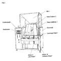
- the overall system according to Fig. 1 leads the substances or mixtures to be separated preferably via a silo (1) in the form of regrind as flakes, granules or geometrically with respect to size and shape any fragments to the detection system.
- a silo (1) in the form of regrind as flakes, granules or geometrically with respect to size and shape any fragments to the detection system.
- the substances - in the exemplary embodiment plastic flakes - isolated by vibrating conveyor (2) and inclined fall surfaces (3) or chutes (4) and cross after acceleration by gravity in a subsequent uniform movement of a laser target band (5).
- each flake (7) is repeatedly hit by the laser beams via optically transparent band-shaped windows (8) and emits substance-specific spectral fingerprints in the form of fluorescent light and / or Raman scattering. From the substance-specific form and the amplitude of the Fingerprints, as already in DE 198 16 881.0 are shown, both the chemical composition and the concentrations of the flakes are determined.
- air pulse nozzles which are lined up in the form of a row-shaped array arrangement parallel and downstream to the laser target band are activated after detection of an undesired substance, thereby directing the relevant unwanted flake on a more external trajectory so that it then falls into one of the "bad flakes” discharge chutes (10), whereas the desired materials pass without directional change into one of the "good flakes” discharge chutes (9) for recycling.
- PET polyethylene terephthalate
- PVC polyvinyl chloride
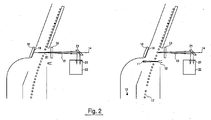
- FIG. 2 shows the beam path in an enlarged view: Collinear laser beams (14) pass first through a perforated deflection mirror (21) and a front screen (16), then pass the product stream of falling flakes until they are on a background plate (18) with reflective layer (19 ) to meet. From there, the laser beams are diffused back. The reflected radiation (15) is supplied by the said deflecting mirror (21) to a spectrometer or sensor (22) with an upstream band stop filter (23), where the evaluation takes place and if necessary the selection of the particle detected by the laser light takes place.
- This intensity attenuation is detected by the spectrometer or sensor (22) and since fluorescence and / or Raman radiation does not occur simultaneously, the particle is recognized as a "bad flake” (11 or 13) and removed from the system by means of compressed air nozzles (12) blown out falling product stream, so that it lands in a discharge chute for the "bad faction”.
- the collinear laser beams (14) which may be identical to the aforementioned laser beams (6), hit the transparent front screen (16) surrounding the laser system and protects the optics from dust, on the background plate (18) with reflective layer (19), which the laser light (14) as diffusely reflected laser light (20) returns to the product stream and then at least partially to the sensor system / spectrometer (22), where the reflected laser light (20) is detected with respect to optical intensity.
- the collinear laser beams (14) hit the transparent front screen (16) surrounding the laser system and protects the optics from dust, on the background plate (18) with reflective layer (19), which the laser light (14) as diffusely reflected laser light (20) returns to the product stream and then at least partially to the sensor system / spectrometer (22), where the reflected laser light (20) is detected with respect to optical intensity.
- an optically inactive material (11) enters the beam path (20) of the laser light (20) reflected by the background plate (18)
- the latter is partially weakened by shading and this weakening is
- Another feature of the invention is the surface coating (19) of the background plate (18) to call.
- this consists of a light-stable and thermally stable reflection layer, which optimally and partially diffusely reflects the laser light. It is essential that the laser light is scattered intensively, without causing fluorescence.
- mineral and / or glass-like layers are suitable for this purpose.
- the reflected light retains its wavelength, whereas the optical fingerprints of the optically active substances change their wavelength and thereby differ substantially spectrally.
- optical spectrum of the incident laser radiation (14) and the spectrum of the backscattered light (20) from the surface (19) of the background plate (18) are detected by a second spectrometer or by the in DE 198 16 881.0 detected spectrometer and clearly distinguished from the optical fingerprints of the optically active substances.
- a second spectrometer or by the in DE 198 16 881.0 detected spectrometer and clearly distinguished from the optical fingerprints of the optically active substances.
- a band stop filter is arranged in front of the spectrometer, which has a blocking effect of about 10 -4 to about 10 -5 . This ensures that the light reflected back from the reflective layer (19) is received by the spectrometer at a similar intensity as the fluorescent light and that glare and premature fatigue of the spectrometer is avoided by the strong laser light.
- the embodiment described above is a specific implementation of the invention.
- the invention can be used in the same way without limiting the universal validity in other arrangements for the detection and discrimination of optically inactive substances of optically active, ie fluorescent and / or Raman scattering having substances.
- the method may not only be as described herein be realized by using laser light, but also by using conventional Planckian radiators or semiconductor light-emitting diodes.
Landscapes
- Physics & Mathematics (AREA)
- Health & Medical Sciences (AREA)
- Life Sciences & Earth Sciences (AREA)
- Chemical & Material Sciences (AREA)
- Analytical Chemistry (AREA)
- Biochemistry (AREA)
- General Health & Medical Sciences (AREA)
- General Physics & Mathematics (AREA)
- Immunology (AREA)
- Pathology (AREA)
- Investigating, Analyzing Materials By Fluorescence Or Luminescence (AREA)
Abstract
Description
- Die Erfindung betrifft ein neues Verfahren und eine Vorrichtung zur Erkennung von optisch inaktiven Fremdmaterialien, wie z.B. Glassplitter, mineralische Produkte, Gummiteilchen, Metall- sowie Keramik-/Steinteilchen usw. in Stoffmischungen. Insbesondere fallen unter diese Anwendungs- kategorie auch sogenannte schwarze Körper, d.h. Stoffe, die optische Strahlung sämtlicher Wellenlängen zu 100 % absorbieren und sich daher den Anwendungsmöglichkeiten der Absorptionsspektroskopie entziehen. Von besonderer Wichtigkeit sind für diese Anwendung auch alle Stoffe, die weder optisch fluoreszieren noch Raman-aktiv sind. Außerdem fallen auch optisch reflektierende Teilchen unter diese Anwendungskategorie.
- Der zunehmende Einsatz von Kunststoffen in verschiedensten Industriebereichen, wie z.B. Lebensmittelindustrie, Automobiltechnik, Pharmazie- und Medizintechnik, Bauindustrie, hat zu einer enormen Steigerung des Verbrauchs von Rohöl geführt. Eine Mehrfachverwendung von Kunststoffen durch Recyclingprozesse zur stoffspezifischen Erkennung und Trennung/Sortierung verschiedener Kunststofftypen ist daher in Zukunft unumgänglich. Da diese Recyclingprozesse ihr Ausgangsmaterial im Wesentlichen aus Sammlungen von Müll beziehen, sind wertlose Verunreinigungen aus bestimmten Stoffen wie Steinchen, Metall, Glas, Keramik, unvermeidlich. Letztere können jedoch im Recycling-Nutzstrom in den meisten Fällen nicht toleriert und müssen daher ausgeschieden werden bevor das rückgewonnene Nutzmaterial seiner Wiederverwendung zugeführt werden kann.
- Die Identifikation und die selektive Trennung von Wertmaterialien ist vor allem durch Einsatz optischer Methoden der Fluoreszenz, Raman-Streuung, und Absorption mit hoher Trennschärfe möglich. Wie aus den Schutzrechten
EP 0606639 ,DE 198 16 881.0 ,DE 101 49 505.6 ersichtlich, wird mit diesen Technologien eine effiziente
Detektion und Trennung auch bei höchsten Prozessgeschwindigkeiten pro Analyse im Mikro- bzw. Nano-Sekunden-Bereich erreicht. Ein großer Nachteil dieser Verfahren beruht jedoch auf der Tatsache, dass optisch inaktive Substanzen damit nicht erfasst werden und damit auch nicht sortiert werden können. - Ziel der vorliegenden Erfindung sind daher ein Verfahren und eine Vorrichtung, die es ermöglichen, optisch inaktive Substanzen in Stoffmischungen wie oben bereits genannt, zu erkennen und auszusortieren.
- Die Erfindung beruht prinzipiell darauf, dass die optische Strahlung, welche durch Laser oder konventionelle Strahlungsquellen erzeugt wird und die zur Anregung von Fluoreszenz, Raman-Streuung und Absorption der betreffenden Stoffe dient, zusätzlich auf eine reflektierende, insbesondere auf eine diffus reflektierende Schicht trifft, von dieser reemittiert und anschließend detektiert wird. Sobald ein inaktives Material in diesen reemittierten Strahl gelangt, wird letzterer teilweise durch Abschattung geschwächt und die Schwächung durch ein Sensorsystem, welches in der Regel einen in diesem Spektralbereich empfindlichen Sensor, ein Sensorarray oder ein Spektrometer darstellt, gemessen. Als Folge wird eine Aktorik wirksam, welche das unerwünschte Material aus dem Nutzstrom entfernt. Der Nutzstrom kann dabei bestehen aus PET-Flakes/PET-Granulat, falls es sich um das Recycling von Polyethylentheraphtalat, z. B. für Anwendungen bei Flaschen oder Behältern in der Getränke- bzw. Lebensmittelindustrie, handelt, oder z.B. aus PVC- oder davon abgetrenntem SMA-Mahlgut als Recycling-Produkte bei der Wiederverwendung von Materialien aus Armaturenbrettern von Automobilen. Ferner kann der Nutzstrom auch beliebige andere Kunststoffteilchen und Fremdstoffe enthalten.
- Besonders zweckmäßig ist es in diesem Zusammenhang, wenn die im re-imitierten Strahl durch inaktive Stoffe erzeugte Abschattung, also die Schwächung der Lichtintensität vom gleichen Sensorsystem erfasst wird, das bereits für die Messung der Fluoreszenz, der Raman-Streuung oder dergleichen dient, um die optisch aktiven Substanzen zu selektieren. Eine solche kombinierte Sensorik ist nicht nur kostengünstig, sondern zeichnet sich auch durch hohe Genauigkeit bei der Detektion aus. Wird beispielsweise eine Fluoreszenzstrahlung bei gleichzeitiger Intensitätsschwächung gemessen, so folgt daraus, dass ein optisch aktives, also ein werthaltiges Teilchen vorliegt. Wird hingegen nur eine Intensitätsschwächung ohne Fluoreszenzstrahlung festgestellt, so handelt es sich um ein optisch inaktives Teilchen, das aussortiert werden soll.
- Das neue Verfahren sowie die daraus abgeleitete Vorrichtung werden im Folgenden anhand der
Figuren 1 und2 näher beschrieben. Dabei sind die wesentlichen Erfindungsmerkmale wie folgt näher dargestellt: - Fig.1:
- zeigt die Frontalansicht des Gesamtsystems bestehend aus optischer Detektionseinheit mit Sortiersystem.
- Fig.2:
- zeigt das Prinzip des optischen Verfahrens zur Detektion von optisch inaktiven Fremdteilchen, die weder fluoreszieren noch Raman-Streuung aufweisen.
- Das Gesamtsystem gemäß
Fig. 1 führt die zu trennenden Stoffe bzw. Stoffgemische vorzugsweise über ein Silo (1) in Form von Mahlgut als Flakes, Granulat oder geometrisch bezüglich Größe und Form beliebigen Bruchstücken dem Detektionssystem zu. Nach dem Silo (1) werden die Stoffe ― im Ausführungsbeispiel Kunststoff-Flakes ― über Vibrationsförderer (2) und geneigte Fallflächen (3) bzw. Fallrinnen (4) vereinzelt und überqueren nach Beschleunigung durch die Schwerkraft in einer sich anschließenden gleichförmigen Bewegung ein Lasertarget Band (5). Durch eine in Bandrichtung erfolgende Hochgeschwindigkeits-Abtastung durch oszillierende, etwa quer zur Fallrichtung (zeilenförmig) scannende Laserstrahlen (6) wird jedes Flake (7) mehrfach über optisch transparente bandförmige Fenster (8) von den Laserstrahlen getroffen, optisch angeregt und emittiert stoffspezifische spektrale Fingerprints in Form von Fluoreszenzlicht und/oder Raman-Streuung. Aus der stoffspezifischen Form und der Amplitude der Fingerprints, wie sie bereits inDE 198 16 881.0 dargestellt sind, werden sowohl die chemische Zusammensetzung als auch die Konzentrationen der Flakes ermittelt. Unterhalb des Lasertarget-Bandes angeordnete Luftimpuls-Düsen, die in Form einer zeilenförmigen Array-Anordnung parallel und stromabwärts zum Lasertarget-Band aufgereiht sind, werden nach Detektion eines nicht erwünschten Stoffes aktiviert, und lenken dadurch das betreffende unerwünschte Flake auf eine weiter außen liegende Flugbahn, so dass es anschließend in einen der Abfuhrschächte (10) für "Schlecht Flakes" fällt, wohingegen die erwünschten Materialien ohne Richtungsänderung in einen der Abfuhrschächte (9) für "Gut Flakes" gelangen, um der Wiederverwertung zugeführt zu werden. Als Beispiel im Rahmen des Recyclings von Plastik für Anwendungen in der Getränke- und Lebensmittelindustrie für Materialien von "Gut Flakes" sei Polyethylentheraphtalat (PET), für "Schlecht Flakes" Polyvinylchlorid (PVC) genannt. Beide Stoffe weisen charakteristische und stark unterschiedliche Fluoreszenz- bzw. Raman-Spektren auf und können daher eindeutig, d.h. stoffspezifisch detektiert und daher in "gut/schlecht"-Fraktionen (9)/(10) getrennt werden. -
Figur 2 zeigt den Strahlengang in vergrößerter Darstellung: Kollineare-Laserstrahlen (14) gehen zunächst durch einen gelochten Ablenkspiegel (21) und eine Frontscheibe (16) hindurch, passieren dann den Produktstrom der herunterfallenden Flakes bis sie auf eine Hintergrundplatte (18) mit reflektierender Schicht (19) treffen. Von dort werden die Laserstrahlen diffus zurückgestrahlt. Die reflektierte Strahlung (15) wird durch den genannten Ablenkspiegel (21) einem Spektrometer oder Sensor (22) mit vorgeschaltetem Bandsperrfilter (23) zugeführt, wo die Auswertung erfolgt und ggf. die Selektion des vom Laserlicht erfassten Teilchens erfolgt. - Treffen die Laserstrahlen (14) wie im rechten Teil von
Figur 2 dargestellt auf ein optisch aktives Teilchen, so lösen sie Fluoreszenz- und/oder Raman-Strahlung aus, die charakteristisch für die Materialbeschaffenheit des Teilchens ist. Der Spektrometer oder Sensor (22) erkennt dieses Teilchen dann als "Gut Flake" (17), das im Produktstrom verbleiben kann. Handelt es sich hingegen um ein optisch inaktives Teilchen, so löst es beim Auftreffen der Laserstrahlen keine Fluoreszenz- und/oder Raman-Strahlung aus, wohl aber eine Abschattung der zur reflektierenden Schicht (19) gerichteten Strahlung wie auch der von ihr zurückgeworfenen Strahlung (20). Diese Intensitätsabschwächung wird von dem Spektrometer oder Sensor (22) erkannt und da nicht gleichzeitig eine Fluoreszenz- und/oder Raman-Strahlung auftritt, wird das Teilchen als "Schlecht Flake" (11 bzw. 13) erkannt und mittels Druckluftdüsen (12) aus dem herabfallenden Produktstrom herausgeblasen, so dass es in einen Abwurfschacht für die "Schlecht Fraktion" landet. - Im. Ergebnis werden also Fremdteilchen (11), die weder Fluoreszenz noch Raman-Streuung aufweisen und daher unerwünscht in die Fraktion für "Gut Flakes" (17) gelangen würden, erkannt und dann über Druckluftdüsen (12) in die "Schlecht Fraktion" (13) oder in eine dritte Fraktion überführt. Während bei optisch aktiven Stoffen die anregenden kollinearen Laserstrahlen (14) wie bereits oben gesagt eine Rückstreuung (15) von Fluoreszenz- und Raman-Strahlung bewirken, fallen letztgenannte bei optisch inaktiven Substanzen aus. Um optisch inaktive Substanzen trotzdem zu erkennen und in Abfuhrschächte (10 bzw. 13) auszuleiten, treffen die kollinearen Laserstrahlen (14), die mit den vorgenannten Laserstrahlen (6) identisch sein können, nach der transparenten Frontscheibe (16), welche das Lasersystem und die Optik vor Staub schützt, auf die Hintergrundplatte (18) mit reflektierender Schicht (19), welche das Laserlicht (14) als diffus reflektiertes Laserlicht (20) wieder auf den Produktstrom und sodann zumindest teilweise dem Sensorsystem/ Spektrometer (22) zuführt, wo das reflektierte Laserlicht (20) bezüglich optischer Intensität detektiert wird. Sobald ein optisch inaktives Material (11) in den Strahlengang (20) des von der Hintergrundplatte (18) reflektierten Laserlichtes (20) gelangt, wird letzteres teilweise durch Abschattung geschwächt und diese Schwächung detektiert. In Folge kann ein Auswurf-Luftimpuls an dem Ventil (12), welches dem jeweiligen Teilchen (11) zugeordnet ist, generiert werden, so dass das unerwünschte Material aus dem PET-Flakestrom ausgeschieden, d.h. in die "Schlecht Fraktion" (13) umgeleitet wird.
- Als weiteres Kennzeichen der Erfindung ist die Oberflächenbeschichtung (19) der Hintergrundplatte (18) zu nennen. Diese besteht erfindungsgemäß aus einer lichtbeständigen und thermisch stabilen Reflektionsschicht, welche das Laserlicht optimal und teilweise diffus reflektiert. Wesentlich dabei ist, dass das Laserlicht intensiv gestreut wird, ohne dass dabei Fluoreszenz erzeugt wird. Dazu eignen sich insbesondere mineralische und/oder glasähnliche Schichten. Das reflektierte Licht, behält seine Wellenlänge, wogegen die optischen Fingerprints der optisch aktiven Substanzen ihre Wellenlänge ändern und sich dadurch ganz wesentlich spektral unterscheiden. Das optische Spektrum der einfallenden Laserstrahlung (14) und das Spektrum des von der Oberfläche (19) der Hintergrundplatte (18) rückgestreuten Lichts (20) werden von einem zweiten Spektrometer oder von dem in
DE 198 16 881.0 beschriebenen Spektrometer detektiert und von den optischen Fingerprints der optisch aktiven Substanzen klar unterschieden. Alternativ zum Spektrometer kann auch ein optischer Sensor eingesetzt werden, der speziell auf die Wellenlängen des einfallenden Laserlichtes (14) selektiv empfindlich ist. - Zweckmäßig ist vor dem Spektrometer ein Bandsperrfilter angeordnet, der eine Sperrwirkung von etwa 10-4 bis etwa 10-5 aufweist. Dadurch ist sichergestellt, dass das von der reflektierenden Schicht (19) rückgestrahlte Licht das in ähnlicher Intensität von dem Spektrometer empfangen wird, wie das fluoreszierende Licht und dass eine Blendung und vorzeitige Ermüdung des Spektrometers durch das starke Laserlicht vermieden wird.
- Das oben beschriebene Ausführungsbeispiel ist eine spezielle Realisierung der Erfindung. Die Erfindung kann in gleicher Weise ohne Einschränkung der universellen Gültigkeit auch in anderen Anordnungen zur Detektion und Unterscheidung optisch inaktiver Substanzen von optisch aktiven, d.h. fluoreszierenden und/oder Raman-Streuung aufweisenden, Stoffen eingesetzt werden. Insbesondere kann das Verfahren nicht nur wie hier beschrieben unter Einsatz von Laserlicht, sondern auch durch Verwendung von konventionellen Planckschen Strahlern oder von Halbleiter-Leuchtdioden realisiert werden.
Claims (7)
- Verfahren zur Detektion von optisch inaktiven Substanzen in einem Gemisch mit optisch, insbesondere bezüglich Fluoreszenz und Raman-Streuung, aktiven Stoffen, wobei die optische Aktivität durch Einstrahlung von Laserlicht und/oder Licht konventioneller Strahlungsquellen und/oder Halbleiter Leuchtdioden zur Stoffdetektion ausgelöst wird, dadurch gekennzeichnet, dass das eingestrahlte Licht oder zusätzlich eingestrahltes Licht zumindest zum Teil auch auf eine reflektierende Schicht (19) trifft und das von dieser Schicht (19) reflektierte Licht zum Nachweis optisch inaktiver Substanzen (11) dient, durch Messung der Lichtreduktion des reflektierten Lichtes infolge von Abschattung durch den inaktiven Stoff.
- Verfahren nach Anspruch 1, dadurch gekennzeichnet, dass als weiteres Unterscheidungsmerkmal zwischen optisch aktiven und optisch inaktiven Substanzen ausgenutzt wird, dass die Spektren des diffus gestreuten Lichtes und die des einfallenden Lichtes identisch sind und dass die Spektren, die durch Fluoreszenz und Raman-Streuung erzeugt werden, zur chemischen Materialbestimmung herangezogen werden.
- Verfahren nach Anspruch 1, dadurch gekennzeichnet, dass das eingestrahlte Licht (5, 6, 14) zur Anregung von Fluoreszenz und Raman-Streuung eingesetzt wird und gleichzeitig auf die reflektierende Schicht (19) trifft, welche zumindest einen Teil (20) der optischen Strahlung reflektiert und dass die reflektierte Strahlung (12) zur Detektion von optisch inaktiven Substanzen durch Abschattung der Strahlung durch diese Substanzen verwendet wird.
- Verfahren nach Anspruch 1, dadurch gekennzeichnet, dass die Schicht (19) das auftretende Licht diffus reflektiert.
- Vorrichtung zur Durchführung des Verfahrens nach einem der Ansprüche 1 bis 4, dadurch gekennzeichnet, dass die reflektierende Schicht (19) auf einer Hintergrundplatte (18) auf der der einfallenden optischen Strahlung zugewandten Seite angeordnet ist.
- Vorrichtung nach Anspruch 5, dadurch gekennzeichnet, dass die reflektierende Schicht (19) aus einer lichtbeständigen thermisch stabilen Reflektionsschicht besteht.
- Vorrichtung nach Anspruch 5, dadurch gekennzeichnet, dass die reflektierende Schicht (19) aus einem glasähnlichen und/oder mineralischen Material besteht.
Applications Claiming Priority (1)
| Application Number | Priority Date | Filing Date | Title |
|---|---|---|---|
| DE102010005768 | 2010-01-25 |
Publications (4)
| Publication Number | Publication Date |
|---|---|
| EP2348304A2 true EP2348304A2 (de) | 2011-07-27 |
| EP2348304A3 EP2348304A3 (de) | 2012-01-04 |
| EP2348304C0 EP2348304C0 (de) | 2023-09-13 |
| EP2348304B1 EP2348304B1 (de) | 2023-09-13 |
Family
ID=43983568
Family Applications (1)
| Application Number | Title | Priority Date | Filing Date |
|---|---|---|---|
| EP11000573.3A Active EP2348304B1 (de) | 2010-01-25 | 2011-01-25 | Vorrichtung zur Detektion und Aussortierung optisch inaktiver Substanzen |
Country Status (4)
| Country | Link |
|---|---|
| EP (1) | EP2348304B1 (de) |
| DE (1) | DE102010048101A1 (de) |
| ES (1) | ES2963391T3 (de) |
| PL (1) | PL2348304T3 (de) |
Cited By (2)
| Publication number | Priority date | Publication date | Assignee | Title |
|---|---|---|---|---|
| CN109759340A (zh) * | 2017-11-09 | 2019-05-17 | 合肥美亚光电技术股份有限公司 | 茶鲜叶分选装置及方法 |
| CN113815154A (zh) * | 2021-11-25 | 2021-12-21 | 广东安拓普聚合物科技有限公司 | 一种塑料再生融化识别分类设备 |
Families Citing this family (2)
| Publication number | Priority date | Publication date | Assignee | Title |
|---|---|---|---|---|
| DE102016215269B4 (de) * | 2016-08-16 | 2020-12-03 | Fraunhofer-Gesellschaft zur Förderung der angewandten Forschung e.V. | Vorrichtung und Verfahren zur Vereinzelung biologischer Zellen |
| DE102018210015B4 (de) * | 2018-06-20 | 2020-04-02 | Fraunhofer-Gesellschaft zur Förderung der angewandten Forschung e.V. | Vorrichtung und Verfahren zur Sortierung von pulverförmigem, partikelförmigem, granulatförmigem oder stückförmigem Material |
Family Cites Families (16)
| Publication number | Priority date | Publication date | Assignee | Title |
|---|---|---|---|---|
| CH558962A (de) * | 1973-06-01 | 1975-02-14 | Landis & Gyr Ag | Vorrichtung zum vergleich der spektralen remission oder transmission eines prueflings und eines standards. |
| DE2606675C3 (de) * | 1976-02-19 | 1979-02-22 | Vladimir Dipl.-Ing. 5100 Aachen Blazek | Anordnung zur spektralanalytischen Untersuchung des Remissionsvermögens einer Probe |
| DE3112308A1 (de) * | 1981-03-28 | 1982-10-14 | Bodenseewerk Perkin-Elmer & Co GmbH, 7770 Überlingen | Kuevettenanordnung fuer ein spektralphotometer |
| JPS58728A (ja) * | 1981-06-25 | 1983-01-05 | Shimadzu Corp | ダイヤモンドカラ−測定装置 |
| DE3406848A1 (de) * | 1984-02-22 | 1985-08-22 | OPTRONIK GmbH opto - elektronische - systeme, 1000 Berlin | Beleuchtungseinrichtung fuer die erzeugung einer diffusen lichtverteilung an der messoeffnung eines hohlkoerpers |
| GB8515132D0 (en) * | 1985-06-14 | 1985-07-17 | British Nuclear Fuels Plc | Measuring photosynthetic activities of plants |
| DE3718500A1 (de) * | 1987-06-02 | 1988-12-22 | Optronik Gmbh Opto Elektronisc | Optische vorrichtung zum messen des lumineszenzanteils bei oberflaechen |
| DE4300169A1 (de) * | 1993-01-07 | 1994-07-14 | Alfill Getraenketechnik | Verfahren und Vorrichtung zum Prüfen von Flaschen |
| GB9526309D0 (en) * | 1995-12-22 | 1996-02-21 | Cme Telemetrix Inc A Company O | Integrating cavity for spectroscopic measurement in light scattering samples |
| DE19816881B4 (de) | 1998-04-17 | 2012-01-05 | Gunther Krieg | Verfahren und Vorrichtung zur Detektion und Unterscheidung zwischen Kontaminationen und Gutstoffen sowie zwischen verschiedenen Farben in Feststoffpartikeln |
| US6369882B1 (en) * | 1999-04-29 | 2002-04-09 | Advanced Sorting Technologies Llc | System and method for sensing white paper |
| DE10149505A1 (de) | 2001-10-02 | 2003-04-10 | Krieg Gunther | Verfahren und Vorrichtung zur Selektierung von Kunststoffen und anderen Materialien bezüglich Farbe und Zusammensetzung |
| TWI247111B (en) * | 2004-09-22 | 2006-01-11 | Chunghwa Picture Tubes Ltd | Method of detecting foreign objects in display manufacture processes |
| DE102005038738A1 (de) * | 2005-08-04 | 2007-02-15 | Helms Technologie Gmbh | Verfahren und Vorrichtung zum Prüfen eines frei fallenden Objekts |
| DE102006029899B4 (de) * | 2006-06-29 | 2009-06-04 | Fresenius Medical Care Deutschland Gmbh | Spektroskopischer Detektor und Verfahren zur Bestimmung von Blut und biologischen Markersubstanzen in Flüssigkeiten |
| BE1017422A3 (nl) * | 2006-12-08 | 2008-09-02 | Visys Nv | Werkwijze en inrichting voor het inspecteren en sorteren van een productstroom. |
-
2010
- 2010-10-09 DE DE102010048101A patent/DE102010048101A1/de active Pending
-
2011
- 2011-01-25 ES ES11000573T patent/ES2963391T3/es active Active
- 2011-01-25 EP EP11000573.3A patent/EP2348304B1/de active Active
- 2011-01-25 PL PL11000573.3T patent/PL2348304T3/pl unknown
Cited By (2)
| Publication number | Priority date | Publication date | Assignee | Title |
|---|---|---|---|---|
| CN109759340A (zh) * | 2017-11-09 | 2019-05-17 | 合肥美亚光电技术股份有限公司 | 茶鲜叶分选装置及方法 |
| CN113815154A (zh) * | 2021-11-25 | 2021-12-21 | 广东安拓普聚合物科技有限公司 | 一种塑料再生融化识别分类设备 |
Also Published As
| Publication number | Publication date |
|---|---|
| EP2348304C0 (de) | 2023-09-13 |
| EP2348304A3 (de) | 2012-01-04 |
| DE102010048101A1 (de) | 2011-07-28 |
| PL2348304T3 (pl) | 2024-03-04 |
| EP2348304B1 (de) | 2023-09-13 |
| ES2963391T3 (es) | 2024-03-26 |
Similar Documents
| Publication | Publication Date | Title |
|---|---|---|
| EP2643103B1 (de) | Verfahren und einrichtung zur einzelkornsortierung von objekten aus schüttgütern | |
| EP1752228B1 (de) | Verfahren und Vorrichtung zur Detektion und Sortierung von Glas | |
| EP1105715B1 (de) | Verfahren und vorrichtung zur detektion und unterscheidung zwischen kontaminationen und gutstoffen sowie zwischen verschiedenen farben in feststoffpartikeln | |
| EP2212035B1 (de) | Vorrichtung und verfahren zur klassifikation transparenter bestandteile in einem materialstrom | |
| DE112017005252B4 (de) | Sortieranlage und Sortierverfahren | |
| DE19840200A1 (de) | Klassiervorrichtung | |
| DE4129754C2 (de) | Verfahren zur Gewinnung sortenreiner Kunststofffraktionen | |
| EP2442921B1 (de) | Verfahren zum erkennen und sortieren von produkten mittels konzentrationserkennung der bestandteile | |
| EP2859963A1 (de) | Vorrichtung und Verfahren zum Sortieren von Schüttgut | |
| EP2716774A1 (de) | Verfahren zur mechanischen Aufbereitung von Aluminiumschrott | |
| EP2348304B1 (de) | Vorrichtung zur Detektion und Aussortierung optisch inaktiver Substanzen | |
| DE102010022455A1 (de) | Verfahren und Vorrichtung zum Erkennen eines ein Zielmineral enthaltenden Objektes | |
| EP1581802B1 (de) | Verfahren und vorrichtung zur selektion von recyclingglas | |
| DE19816881B4 (de) | Verfahren und Vorrichtung zur Detektion und Unterscheidung zwischen Kontaminationen und Gutstoffen sowie zwischen verschiedenen Farben in Feststoffpartikeln | |
| DE102017119137A1 (de) | Verfahren zur Detektion und Aussonderung von Sonderglas aus Recyclingglas | |
| EP3268725B1 (de) | Verfahren und vorrichtung zur identifizierung von kunststoffen und deren additiven | |
| EP2110187A1 (de) | Verfahren zum Identifizieren, Klassifizieren und Sortieren von Gegenständen, Objekten und Materialien, sowie ein Erkennungssystem zur Durchführung dieses Verfahrens | |
| EP1300200B1 (de) | Verfahren und Vorrichtung zur Identifikation und Separation von Kunststoffmaterialteilchen | |
| DE102019129726A1 (de) | Prüfsystem zur prüfung von behältern und abfüllanlage mit einem derartigen prüfsystem | |
| DE102018210015B4 (de) | Vorrichtung und Verfahren zur Sortierung von pulverförmigem, partikelförmigem, granulatförmigem oder stückförmigem Material | |
| EP3183072B1 (de) | Sortieranlage und verfahren zur trennung von materialfraktionen | |
| DE102005003406B4 (de) | Verfahren und Vorrichtung zum Recycling von Glaskeramiken | |
| EP3320326A1 (de) | Vorrichtung und verfahren zur messung von niederschlag | |
| DE202020102172U1 (de) | Fördervorrichtung mit verbesserter Schwerteileerkennung | |
| DE202004009165U1 (de) | Vorrichtung zur Sortierung von lichtbrechenden Partikeln |
Legal Events
| Date | Code | Title | Description |
|---|---|---|---|
| PUAI | Public reference made under article 153(3) epc to a published international application that has entered the european phase |
Free format text: ORIGINAL CODE: 0009012 |
|
| AK | Designated contracting states |
Kind code of ref document: A2 Designated state(s): AL AT BE BG CH CY CZ DE DK EE ES FI FR GB GR HR HU IE IS IT LI LT LU LV MC MK MT NL NO PL PT RO RS SE SI SK SM TR |
|
| AX | Request for extension of the european patent |
Extension state: BA ME |
|
| PUAL | Search report despatched |
Free format text: ORIGINAL CODE: 0009013 |
|
| AK | Designated contracting states |
Kind code of ref document: A3 Designated state(s): AL AT BE BG CH CY CZ DE DK EE ES FI FR GB GR HR HU IE IS IT LI LT LU LV MC MK MT NL NO PL PT RO RS SE SI SK SM TR |
|
| AX | Request for extension of the european patent |
Extension state: BA ME |
|
| RIC1 | Information provided on ipc code assigned before grant |
Ipc: G01N 21/85 20060101ALI20111130BHEP Ipc: G01N 21/59 20060101ALI20111130BHEP Ipc: B07C 5/34 20060101ALI20111130BHEP Ipc: B07C 5/12 20060101ALI20111130BHEP Ipc: G01N 21/47 20060101AFI20111130BHEP |
|
| 17P | Request for examination filed |
Effective date: 20120328 |
|
| STAA | Information on the status of an ep patent application or granted ep patent |
Free format text: STATUS: EXAMINATION IS IN PROGRESS |
|
| 17Q | First examination report despatched |
Effective date: 20200107 |
|
| GRAP | Despatch of communication of intention to grant a patent |
Free format text: ORIGINAL CODE: EPIDOSNIGR1 |
|
| STAA | Information on the status of an ep patent application or granted ep patent |
Free format text: STATUS: GRANT OF PATENT IS INTENDED |
|
| INTG | Intention to grant announced |
Effective date: 20230404 |
|
| GRAS | Grant fee paid |
Free format text: ORIGINAL CODE: EPIDOSNIGR3 |
|
| GRAA | (expected) grant |
Free format text: ORIGINAL CODE: 0009210 |
|
| STAA | Information on the status of an ep patent application or granted ep patent |
Free format text: STATUS: THE PATENT HAS BEEN GRANTED |
|
| AK | Designated contracting states |
Kind code of ref document: B1 Designated state(s): AL AT BE BG CH CY CZ DE DK EE ES FI FR GB GR HR HU IE IS IT LI LT LU LV MC MK MT NL NO PL PT RO RS SE SI SK SM TR |
|
| REG | Reference to a national code |
Ref country code: GB Ref legal event code: FG4D Free format text: NOT ENGLISH |
|
| REG | Reference to a national code |
Ref country code: CH Ref legal event code: EP |
|
| REG | Reference to a national code |
Ref country code: DE Ref legal event code: R096 Ref document number: 502011017444 Country of ref document: DE |
|
| REG | Reference to a national code |
Ref country code: IE Ref legal event code: FG4D Free format text: LANGUAGE OF EP DOCUMENT: GERMAN |
|
| U01 | Request for unitary effect filed |
Effective date: 20231004 |
|
| U07 | Unitary effect registered |
Designated state(s): AT BE BG DE DK EE FI FR IT LT LU LV MT NL PT SE SI Effective date: 20231013 |
|
| REG | Reference to a national code |
Ref country code: NO Ref legal event code: T2 Effective date: 20230913 |
|
| PG25 | Lapsed in a contracting state [announced via postgrant information from national office to epo] |
Ref country code: GR Free format text: LAPSE BECAUSE OF FAILURE TO SUBMIT A TRANSLATION OF THE DESCRIPTION OR TO PAY THE FEE WITHIN THE PRESCRIBED TIME-LIMIT Effective date: 20231214 |
|
| PG25 | Lapsed in a contracting state [announced via postgrant information from national office to epo] |
Ref country code: RS Free format text: LAPSE BECAUSE OF FAILURE TO SUBMIT A TRANSLATION OF THE DESCRIPTION OR TO PAY THE FEE WITHIN THE PRESCRIBED TIME-LIMIT Effective date: 20230913 Ref country code: HR Free format text: LAPSE BECAUSE OF FAILURE TO SUBMIT A TRANSLATION OF THE DESCRIPTION OR TO PAY THE FEE WITHIN THE PRESCRIBED TIME-LIMIT Effective date: 20230913 Ref country code: GR Free format text: LAPSE BECAUSE OF FAILURE TO SUBMIT A TRANSLATION OF THE DESCRIPTION OR TO PAY THE FEE WITHIN THE PRESCRIBED TIME-LIMIT Effective date: 20231214 |
|
| U20 | Renewal fee for the european patent with unitary effect paid |
Year of fee payment: 14 Effective date: 20240105 |
|
| REG | Reference to a national code |
Ref country code: ES Ref legal event code: FG2A Ref document number: 2963391 Country of ref document: ES Kind code of ref document: T3 Effective date: 20240326 |
|
| PG25 | Lapsed in a contracting state [announced via postgrant information from national office to epo] |
Ref country code: IS Free format text: LAPSE BECAUSE OF FAILURE TO SUBMIT A TRANSLATION OF THE DESCRIPTION OR TO PAY THE FEE WITHIN THE PRESCRIBED TIME-LIMIT Effective date: 20240113 |
|
| PG25 | Lapsed in a contracting state [announced via postgrant information from national office to epo] |
Ref country code: SM Free format text: LAPSE BECAUSE OF FAILURE TO SUBMIT A TRANSLATION OF THE DESCRIPTION OR TO PAY THE FEE WITHIN THE PRESCRIBED TIME-LIMIT Effective date: 20230913 Ref country code: RO Free format text: LAPSE BECAUSE OF FAILURE TO SUBMIT A TRANSLATION OF THE DESCRIPTION OR TO PAY THE FEE WITHIN THE PRESCRIBED TIME-LIMIT Effective date: 20230913 Ref country code: IS Free format text: LAPSE BECAUSE OF FAILURE TO SUBMIT A TRANSLATION OF THE DESCRIPTION OR TO PAY THE FEE WITHIN THE PRESCRIBED TIME-LIMIT Effective date: 20240113 Ref country code: CZ Free format text: LAPSE BECAUSE OF FAILURE TO SUBMIT A TRANSLATION OF THE DESCRIPTION OR TO PAY THE FEE WITHIN THE PRESCRIBED TIME-LIMIT Effective date: 20230913 Ref country code: SK Free format text: LAPSE BECAUSE OF FAILURE TO SUBMIT A TRANSLATION OF THE DESCRIPTION OR TO PAY THE FEE WITHIN THE PRESCRIBED TIME-LIMIT Effective date: 20230913 |
|
| REG | Reference to a national code |
Ref country code: DE Ref legal event code: R097 Ref document number: 502011017444 Country of ref document: DE |
|
| PLBE | No opposition filed within time limit |
Free format text: ORIGINAL CODE: 0009261 |
|
| STAA | Information on the status of an ep patent application or granted ep patent |
Free format text: STATUS: NO OPPOSITION FILED WITHIN TIME LIMIT |
|
| 26N | No opposition filed |
Effective date: 20240614 |
|
| PG25 | Lapsed in a contracting state [announced via postgrant information from national office to epo] |
Ref country code: MC Free format text: LAPSE BECAUSE OF FAILURE TO SUBMIT A TRANSLATION OF THE DESCRIPTION OR TO PAY THE FEE WITHIN THE PRESCRIBED TIME-LIMIT Effective date: 20230913 |
|
| PG25 | Lapsed in a contracting state [announced via postgrant information from national office to epo] |
Ref country code: MC Free format text: LAPSE BECAUSE OF FAILURE TO SUBMIT A TRANSLATION OF THE DESCRIPTION OR TO PAY THE FEE WITHIN THE PRESCRIBED TIME-LIMIT Effective date: 20230913 |
|
| PG25 | Lapsed in a contracting state [announced via postgrant information from national office to epo] |
Ref country code: IE Free format text: LAPSE BECAUSE OF NON-PAYMENT OF DUE FEES Effective date: 20240125 |
|
| PG25 | Lapsed in a contracting state [announced via postgrant information from national office to epo] |
Ref country code: IE Free format text: LAPSE BECAUSE OF NON-PAYMENT OF DUE FEES Effective date: 20240125 |
|
| U20 | Renewal fee for the european patent with unitary effect paid |
Year of fee payment: 15 Effective date: 20250110 |
|
| PG25 | Lapsed in a contracting state [announced via postgrant information from national office to epo] |
Ref country code: CY Free format text: LAPSE BECAUSE OF FAILURE TO SUBMIT A TRANSLATION OF THE DESCRIPTION OR TO PAY THE FEE WITHIN THE PRESCRIBED TIME-LIMIT; INVALID AB INITIO Effective date: 20110125 |
|
| PG25 | Lapsed in a contracting state [announced via postgrant information from national office to epo] |
Ref country code: HU Free format text: LAPSE BECAUSE OF FAILURE TO SUBMIT A TRANSLATION OF THE DESCRIPTION OR TO PAY THE FEE WITHIN THE PRESCRIBED TIME-LIMIT; INVALID AB INITIO Effective date: 20110125 |
|
| PG25 | Lapsed in a contracting state [announced via postgrant information from national office to epo] |
Ref country code: TR Free format text: LAPSE BECAUSE OF FAILURE TO SUBMIT A TRANSLATION OF THE DESCRIPTION OR TO PAY THE FEE WITHIN THE PRESCRIBED TIME-LIMIT Effective date: 20230913 |
|
| U20 | Renewal fee for the european patent with unitary effect paid |
Year of fee payment: 16 Effective date: 20251212 |
|
| REG | Reference to a national code |
Ref country code: CH Ref legal event code: U11 Free format text: ST27 STATUS EVENT CODE: U-0-0-U10-U11 (AS PROVIDED BY THE NATIONAL OFFICE) Effective date: 20260201 |
|
| PGFP | Annual fee paid to national office [announced via postgrant information from national office to epo] |
Ref country code: GB Payment date: 20260122 Year of fee payment: 16 |
|
| PGFP | Annual fee paid to national office [announced via postgrant information from national office to epo] |
Ref country code: ES Payment date: 20260217 Year of fee payment: 16 |
|
| PGFP | Annual fee paid to national office [announced via postgrant information from national office to epo] |
Ref country code: NO Payment date: 20260120 Year of fee payment: 16 |
|
| PGFP | Annual fee paid to national office [announced via postgrant information from national office to epo] |
Ref country code: CH Payment date: 20260201 Year of fee payment: 16 |
|
| PGFP | Annual fee paid to national office [announced via postgrant information from national office to epo] |
Ref country code: PL Payment date: 20260112 Year of fee payment: 16 |