EP2348298A1 - Combustion pressure sensor - Google Patents
Combustion pressure sensor Download PDFInfo
- Publication number
- EP2348298A1 EP2348298A1 EP11151011A EP11151011A EP2348298A1 EP 2348298 A1 EP2348298 A1 EP 2348298A1 EP 11151011 A EP11151011 A EP 11151011A EP 11151011 A EP11151011 A EP 11151011A EP 2348298 A1 EP2348298 A1 EP 2348298A1
- Authority
- EP
- European Patent Office
- Prior art keywords
- housing
- fixed
- flexible member
- axis
- internal combustion
- Prior art date
- Legal status (The legal status is an assumption and is not a legal conclusion. Google has not performed a legal analysis and makes no representation as to the accuracy of the status listed.)
- Granted
Links
Images


Classifications
-
- G—PHYSICS
- G01—MEASURING; TESTING
- G01L—MEASURING FORCE, STRESS, TORQUE, WORK, MECHANICAL POWER, MECHANICAL EFFICIENCY, OR FLUID PRESSURE
- G01L23/00—Devices or apparatus for measuring or indicating or recording rapid changes, such as oscillations, in the pressure of steam, gas, or liquid; Indicators for determining work or energy of steam, internal-combustion, or other fluid-pressure engines from the condition of the working fluid
- G01L23/08—Devices or apparatus for measuring or indicating or recording rapid changes, such as oscillations, in the pressure of steam, gas, or liquid; Indicators for determining work or energy of steam, internal-combustion, or other fluid-pressure engines from the condition of the working fluid operated electrically
-
- G—PHYSICS
- G01—MEASURING; TESTING
- G01L—MEASURING FORCE, STRESS, TORQUE, WORK, MECHANICAL POWER, MECHANICAL EFFICIENCY, OR FLUID PRESSURE
- G01L23/00—Devices or apparatus for measuring or indicating or recording rapid changes, such as oscillations, in the pressure of steam, gas, or liquid; Indicators for determining work or energy of steam, internal-combustion, or other fluid-pressure engines from the condition of the working fluid
- G01L23/22—Devices or apparatus for measuring or indicating or recording rapid changes, such as oscillations, in the pressure of steam, gas, or liquid; Indicators for determining work or energy of steam, internal-combustion, or other fluid-pressure engines from the condition of the working fluid for detecting or indicating knocks in internal-combustion engines; Units comprising pressure-sensitive members combined with ignitors for firing internal-combustion engines
Definitions
- the present invention relates to a combustion pressure sensor for detecting combustion pressure within a combustion chamber.
- a combustion pressure sensor for detecting combustion pressure includes a tubular housing having an axial hole extending in the direction of an axis; a rodlike pressure transmission body inserted into the axial hole such that its front end portion is exposed to the outside; and a sensor element which outputs a signal on the basis of a pressure applied thereto from the pressure transmission body.
- the housing includes a main body portion which has, on its outer circumferential surface, a screw portion for screw engagement with a mounting hole of an internal combustion engine; and a cap member joined to a front end portion of the main body portion.
- a portion of the housing located between the front end of the screw portion and the press contact portion may contract along the axial direction due to an axial force generated as a result of the screw coupling, deformation of an engine head at the time of combustion, etc. If the housing contracts, a force along the axial direction acts on the pressure transmission body via the flexible member. As a result, the force along the axial direction is added to the pressure transmitted from the pressure transmission body to the sensor element. In such a case, the sensor element may fail to accurately detect the combustion pressure.
- the present invention has been conceived in view of the above circumstances, and an object of the invention is to provide a combustion pressure sensor which can improve the detection accuracy of combustion pressure through reduction of contractive deformation of a main body portion of a housing of the sensor, which deformation occurs when the combustion pressure sensor is attached to an internal combustion engine.
- a combustion pressure sensor of the present configuration comprises:
- the cap member contracts more easily than does the main body portion. Accordingly, when the combustion pressure sensor is attached to an internal combustion engine, the cap member which does not affect the pressure transmission body even when it deforms compressively can be caused to deform to a greater degree, and the amount of deformation of the main body portion which affects the pressure transmission body can be made relatively small. As a result, the force along the axial direction applied to the pressure transmission body as a result of deformation of the main body portion can be reduced effectively, and the detection accuracy of combustion pressure can be improved.
- a combustion pressure sensor of the present configuration comprises:
- one end of the flexible member is fixed to the housing on the front end side of a portion of the housing located at the center between the rear end of the screw portion and the press contact portion. Therefore, the length of the flexible member as measured along the axis can be made relatively short, and the pressure transmission body can be held in a more stable state. As a result, the detection accuracy of combustion pressure can be improved further.
- a combustion pressure sensor of the present configuration comprises:
- the Young's modulus of the cap member is made smaller than that of the main body portion. Therefore, when a force along the direction of the axis is applied, the cap member contracts more easily than does the main body portion. Accordingly, when the combustion pressure sensor is attached to an internal combustion engine, the cap member which does not affect the pressure transmission body even when it deforms compressively can be caused to deform to a greater degree, and the amount of deformation of the main body portion which affects the pressure transmission body can be made relatively small. As a result, the force along the axial direction applied to the pressure transmission body as a result of deformation of the main body portion can be reduced effectively, and the detection accuracy of combustion pressure can be improved.
- a combustion pressure sensor of the present configuration comprises:
- a thin wall portion is provided on the cylindrical tubular portion of the cap member. Therefore, when the combustion pressure sensor is attached to an internal combustion engine, the cap member can be caused to deform to a greater degree, and the amount of deformation of the main body portion can be made relatively small. As a result, the force along the axial direction applied to the pressure transmission body as a result of deformation of the main body portion can be reduced effectively, and the detection accuracy of combustion pressure can be improved.
- a combustion pressure sensor of the present configuration comprises:
- a portion of the housing which affects the pressure transmission body through its compressive deformation (a portion of the housing between the portion to which the sensor element is fixed and the portion to which the flexible member is fixed) can be shortened further. Therefore, the force along the axial direction applied to the pressure transmission body when the combustion pressure sensor is attached to an internal combustion engine can be reduced effectively.
- a portion of the housing which does not affect the pressure transmission body even when it deforms compressively contracts more greatly than does a portion of the housing which affects the pressure transmission body when it deforms compressively (a portion of the housing between the portion to which the sensor element is fixed and the portion to which the flexible member is fixed). Therefore, the force along the axial direction applied to the pressure transmission body when the combustion pressure sensor is attached to an internal combustion engine can be reduced further, and the detection accuracy of combustion pressure can be improved further.
- a combustion pressure sensor of the present configuration comprises:
- a portion of the housing which does not affect the pressure transmission body even when it deforms compressively contracts more greatly than does a portion of the housing which affects the pressure transmission body when it deforms compressively. Therefore, the force along the axial direction applied to the pressure transmission body when the combustion pressure sensor is attached to an internal combustion engine can be reduced further, and the detection accuracy of combustion pressure can be improved further.
- a combustion pressure sensor of the present configuration is a combustion pressure sensor according to any one of Configurations 1 to 6, wherein at least a portion of the exposed front end portion of the pressure transmission body is a heat generation unit.
- At least a portion of the exposed front end portion of the pressure transmission body may be formed by a heat generation unit which imparts to the combustion pressure sensor a function of heating the interior of a combustion chamber.
- a heat generation unit which imparts to the combustion pressure sensor a function of heating the interior of a combustion chamber.
- FIG 1 is a partially sectioned front view showing an example of a combustion pressure sensor having a function of heating the interior of a combustion chamber.
- a combustion pressure sensor having a heating function (hereinafter referred to as a “combustion pressure sensor”) 1 includes a tubular housing 2; a pressure transmission body 3 whose front end portion is exposed from the front end of the housing 2; and a sensor structure 4 for detecting combustion pressure.
- the housing 2 is composed of a main body portion 21 and a cap member 22 each of which has a tubular shape and which are joined together.
- the housing 2 has an axial hole 23 extending therethrough in the direction of an axis CL1.
- the main body portion 21 is formed of a predetermined metallic material.
- the main body portion 21 has, on its outer circumferential surface, a screw portion 24 to be screwed into a mounting hole of an internal combustion engine such as a diesel engine, and a tool engagement portion 25 which has a hexagonal cross section and with which a tool such as a torque wrench is engaged.
- the cap member 22 is formed of a predetermined metallic material, and its rear end portion is joined to a front end portion of the main body portion 21.
- the cap member 22 has a press contact portion 26, and a tubular cylindrical portion 27 extending rearward from the press contact portion 26 along the axis CL1.
- the press contact portion 26 is formed to have a wall thickness (thickness in the radial direction) greater than that of the cylindrical portion 27, and has a taper surface 26a tapered frontward in the direction of the axis CL1.
- the pressure transmission body 3 is composed of a barlike heat generation unit 31 and a tubular sleeve 32 connected together in series.
- the heat generation unit 31 is configured such that a heat generation coil 34 and a control coil 35 are placed in a tube 33 along with insulating powder 36 such as powder of magnesium oxide.
- the tube 33 is formed of a metallic material (e.g., Inconel, a stainless steel alloy, etc.) which contains iron (Fe) or nickel (Ni) as the main component, and has a closed front end portion.
- the tube 33 has, on its rear end side, a press-fit large diameter portion 33a which is formed by means of a swaging process or the like and which has a relatively large outer diameter. Meanwhile, the tube 33 has, on its front end side, a heat generation portion 33b which is smaller in diameter than the press-fit large diameter portion 33a and in which the heat generation coil 34 is accommodated.
- the heat generation coil 34 and the control coil 35 are connected together in series, and a front end portion of the heat generation coil 34 is joined to a front end portion of the tube 33.
- the heat generation coil 34 is formed from a resistance heating wire which contains Fe (main component), chromium (Cr), aluminum (A1), etc.
- the control coil 35 is formed of a material which is greater in temperature coefficient of electrical resistivity than the material of the heat generation coil 34; for example, formed from a resistance heating wire made of a material whose main component is Co or Ni (e.g., cobalt (Co)-Ni-Fe alloy).
- the control coil 35 increases its electrical resistance as a result of its own heat generation or as a result of receipt of heat generated by the heat generation coil 34, to thereby control the amount of electric power supplied to the heat generation coil 34. That is, at the beginning of energization, a relatively large amount of electric power is supplied to the heat generation coil 34, so that the temperature of the heat generation coil 34 increases sharply. Meanwhile, when the heat generation of the heat generation coil 34 proceeds, the control coil 35 is heated by heat such as the heat generated by the heat generation coil 34, and the electrical resistance of the control coil 35 increases. As a result, the amount of electric power supplied to the heat generation coil 34 decreases.
- the heat generation unit 31 has a temperature rising characteristic such that, after the rapid temperature rising at the beginning of energization, the supply of electric power is restricted by the action of the control coil 35, whereby the temperature becomes saturated. That is, since the control coil 35 is provided, it is possible to prevent excessive increase (overshoot) of the temperature of the heat generation coil 34 while enhancing the rapid temperature rising performance.
- a predetermined external controller may be used so as to adjust the amount of electric power supplied to the heat generation coil 34 to thereby control the heat generation of the heat generation coil 34.
- the control coil 35 can prevent an excessive temperature rising of the heat generation coil 34, which would otherwise occur when the external controller fails. That is, the control coil 35 may be used so as to positively adjust the amount of electric power supplied to the heat generation coil 34, or may be used so as to prevent the supply of overcurrent to the heat generation coil 34, which would otherwise occur, for example, as a result of failure of the external controller.
- the insulating powder 36 is charged around the heat generation coil 34 and the control coil 35 within the tube 33. Therefore, whereas the front end portion of the heat generation coil 34 is electrically connected to the tube 33, the outer circumferential surfaces of the heat generation coil 34 and the control coil 35 are electrically insulated from the inner circumferential surface of the tube 33 by means of the insulating powder 36.
- a center rod 5 formed of a metal and extending in the direction of the axis CL1 is provided in the axial hole 23.
- a front end portion of the center rod 5 is inserted into the tube 33, and is electrically connected to the control coil 35.
- An electrically conductive terminal fitting 6 is fixed to a rear end portion of the center rod 5. Electric power is supplied to the heat generation coil 34 via the terminal fitting 6 and the center rod 5.
- an annular rubber member 7 is provided between a rear end portion of the tube 33 and the center rod 5 so as to seal the interior of the tube 33.
- the pressure transmission body 3 (the heat generation unit 31) is held by the main body portion 21 via a tubular flexible member 8 formed of a metal (e.g., SUS).
- the main body portion 21 has a tubular projection 28, which projects frontward, with respect to the direction of the axis CL1, from a front end portion of the main body portion 21.
- the projection 28 is press-fitted into a rear end portion of the flexible member 8. That is, the rear end portion of the flexible member 8 is fixed to the housing 2 on the front end side of a portion of the housing 2 located at the center between the rear end of the screw portion 24 and the press contact portion 26. Meanwhile, the press-fit large diameter portion 33a of the tube 33 is press-fitted into and is joined to a front end portion of the flexible member 8.
- the pressure transmission body 3 is held by the main body portion 21.
- the flexible member 8 has, at its generally central portion, a bellows portion 81, which is displaceable through expanding and contracting itself along the direction of the axis CL1.
- the flexible member 8 can expand and contract along the direction of the axis CL1.
- the bellows portion 81 of the flexible member 8 contracts, and, with this deformation, the heat generation unit 31 held by the flexible member 8 moves rearward in relation to the housing 2.
- the sleeve 32 is formed of a predetermined metallic material, and is provided on the radially outer side of the center rod 5 such that a clearance is formed between the sleeve 32 and the inner circumferential surface of the axial hole 23, and a clearance is formed between the sleeve 32 and the outer circumferential surface of the center rod 5.
- a rear end portion of the heat generation unit 31 is press-fitted into and joined to a front end portion of the sleeve 32. Therefore, when the heat generation unit 31 moves in relation to the housing 2, the sleeve 32 also moves in relation to the housing 2.
- An annular insulating rubber member 9 is inserted between a rear end portion of the sleeve 32 and the center rod 5.
- the insulating rubber member 9 prevents deflective movement of a rear end portion of the center rod 5, which would otherwise occur because of vibration, and avoids contact between the center rod 5 and the sleeve 32.
- An annular grove 37 which is centered at the axis CL1, is formed on an outer circumferential surface of the sleeve 32 at a generally central position along the axis CL1.
- An annular O-ring 10 is disposed in the groove 37. The O-ring 10 is configured such that it comes into contact with both the sleeve 32 and the main body portion 21.
- the sensor structure 4 is joined to the rear end of the main body portion 21.
- the sensor structure 4 is composed of a casing 41 and various components disposed within the casing 41, such as a sensor element 42, a distortion member 43, and a relay member 44.
- the casing 41 assumes a cylindrical tubular shape, and has, at its rear end, a rear wall portion (upper wall portion) having a hole through which the center rod 5 can be passed.
- a tubular attachment portion 29 projecting from a rear end portion of the main body portion 21 is inserted into the casing 41. In this state, the casing 41 and the attachment portion 29 are joined together, whereby the sensor structure 4 is joined to the main body portion 21.
- the distortion member 43 provided within the casing 41 assumes an annular shape, and has an inner wall portion 43a having an outer diameter approximately equal to that of the sleeve 32, an outer wall portion 43b in contact with the inner circumferential surface of the casing 41, and a rear wall portion 43c connecting the two wall portions 43a and 43b.
- the relay member 44 provided in the casing 41 assumes a cylindrical tubular shape, and has a rear wall portion 44c having a hole through which the center rod 5 can be passed. The relay member 44 is placed on the distortion member 43, and the outer circumferential surfaces of the distortion member 43 and the relay member 44 are fixed to the inner circumferential surface of the casing 41.
- a rear end portion of the sleeve 32 is joined to a front end portion of the inner wall portion 43a of the distortion member 43. Accordingly, when the sleeve 32 moves relatively as a result of the heat generation unit 31 receiving a pressure, the rear wall portion 43c of the distortion member 43 is pushed by the sleeve 32 and deforms.
- the above-mentioned sensor element 42 is disposed on the rear wall portion 43c of the distortion member 43.
- the sensor element 42 is composed of, for example, a known semiconductor stain gauge which includes piezoresistance elements formed on a semiconductor substrate such as a silicon substrate.
- the resistance of the sensor element 42 changes in accordance with the degree of deformation of the rear wall portion 43c of the distortion member 43.
- a relay substrate 45 is disposed on the rear wall portion 44c of the relay member 44 facing the rear wall portion 43c of the distortion member 43.
- the relay substrate 45 is electrically connected to the sensor element 42 by means of wire boding or flexible cable (not shown), and has a function of converting the resistance of the sensor element 42 to a voltage, and amplifying the voltage.
- the amplified voltage is output to an external circuit such as an ECU (not shown) via a cable 46 connected to the relay member 44.
- the housing is formed of a material having a relatively high Young's modulus (e.g., carbon steel, SUS, or the like). That is, the Young's modulus of the cap member 22 is made smaller than that of the main body portion 21.
- the heat generation unit 31 is manufactured. Specifically, a resistance heating wire containing Fe as the main component is formed into a coil shape so as to obtain the heat generation coil 34, and a resistance heating wire made of a Co alloy or the like is formed into a coil shape so as to obtain the control coil 35. A rear end portion of the heat generation coil 34 and a front end portion of the control coil 35 are joined together. Subsequently, the front end of the center rod 5 and the heat generation coil 34 and the control coil 35 united with the center rod 5 are placed in the tube 33 whose front end has not yet been closed. By means of arc welding, the front end portion of the tube 33 is closed, and a front end portion of the heat generation coil 34 is joined to the front end portion of the tube 33.
- the insulating powder 36 is charged into the tube 33, and swaging is performed on the tube 33.
- the fit-in large diameter portion 33a and the heat generation portion 33b are formed on the tube 33, and the heat generation unit 31 united with the center rod 5 is obtained.
- the main body 21, which has the axial hole 23, the screw portion 24, etc., is manufactured by means of performing forging, rolling, or a like process on a predetermined alloy.
- an alloy whose Young's modulus is smaller than that of the alloy that constitutes the main body portion 21 is prepared, and forging or a like process is performed on the prepared alloy, to thereby manufacture the cap member 22.
- forging or a like process is performed on a predetermined alloy, to thereby obtain the sleeve 32.
- the sleeve 32 is disposed on the outer circumferential side of the center rod 5. Then, the front end portion of the sleeve 32 and the rear end portion of the heat generation unit 31 (the tube 33) are joined together by means of laser welding.
- the insulating rubber member 9 is inserted between the rear end portion of the sleeve 32 and the center rod 5 after the joining of the sleeve 32 and the heat generation unit 31, and the rear end portion of the sleeve 32 and the distortion member 43 (the inner wall portion 43a) of the sensor structure 4 are joined together.
- the O-ring 10 is disposed on the outer circumference of the sleeve 32, and the heat generation unit 31 and the sleeve 32 are inserted into the main body portion 21 from its rear end opening.
- the casing 41 of the sensor structure 4 is joined to the rear end portion of the main body portion 21.
- the terminal fitting 6 is press-fitted onto and joined to the rear end portion of the center rod 5 projecting rearward from the sensor structure 4.
- the above-described heat generation unit 31 is passed through the flexible member 8, which is manufactured in advance.
- a laser beam is applied to the outer circumferential surface of the flexible member 8 so as to join the rear end portion of the flexible member 8 and the main body portion 21.
- the heat generation unit 31 (the tube 33) is joined to the front end portion of the flexible member 8.
- the Young's modulus of the cap member 22 is made smaller than that of the main body portion 21. Therefore, when a force along the direction of the axis CL1 is applied, the cap member 22 contracts more easily than does the main body portion 21. Accordingly, when the combustion pressure sensor 1 is attached to the internal combustion engine EN, the cap member 22, which does not affect the pressure transmission body 3 even when it deforms compressively, is caused to deform in a greater amount, and the amount of deformation of the main body portion 21, which affects the pressure transmission body 3, can be made relatively small. As a result, the force along the axial direction which acts on the pressure transmission body 3 as a result of deformation of the main body portion 21 can be reduced effectively, and the detection accuracy of combustion pressure can be improved.
- the rear end portion of the flexible member 8 is fixed to the housing 2 on the front end side of a portion of the housing 2 located at the center between the rear end of the screw portion 24 and the press contact portion 26. Therefore, the length of the flexible member 8, as measured along the axis CL1, can be made relatively short, whereby the pressure transmission body 3 can be held in a more stable state. As a result, the detection accuracy of combustion pressure can be improved further.
- a combustion pressure sensor 101 differs from the first embodiment in the structure of a cap member 122.
- the cap member 122 includes a press contact portion 126 having a relatively large wall thickness, and a cylindrical portion 127 extending along the axis CL1 from the rear end of the press contact portion 126.
- An annular groove centered at the axis CL1 is formed on the outer circumferential surface of the cylindrical portion 127, whereby a thin wall portion 127a is provided.
- the cap member 122 is formed of the same metallic material (e.g., carbon steel, SUS or the like) as the main body portion 21.
- the cylindrical portion 127 of the cap member 122 has the thin wall portion 127a. Therefore, when the combustion pressure sensor 101 is attached to the internal combustion engine EN, the cap member 122 can be caused to deform in a greater amount, and the amount of deformation of the main body portion 21 can be made relatively small. Thus, the force along the axial direction which acts on the pressure transmission body 3 as a result of deformation of the main body portion 21 can be reduced, and the detection accuracy of combustion pressure can be improved.
- a sensor element 242 is provided within a housing 202, and is fixed indirectly to a portion of the housing 202 located between the front end of a screw portion 224 and the front end of a press contact portion 226.
- the sensor element 242 is fixed to the housing 202 via a tubular sleeve 251 having a portion disposed between and fixed to a main body portion 221 of the housing 202 and a cap member 222, and a pedestal 252 disposed within a rear end portion of the sleeve 251.
- a stopper member 253 fitted into the sleeve 251 restricts at least rearward movement of the pedestal 252.
- the cap member 222 includes a first member 261 having the press contact portion 226, and a second member 262 joined to the rear end of the first member 261.
- a tubular projection 271 is provided at the front end of the second member 262.
- the projection 271 has an outer diameter smaller than the inner diameter of the first member 261, and is separated from the first member 261 in the radial direction.
- a flexible member 208 is fixed to the second member 262 (the housing 202) via the projection 271. That is, one end of the flexible member 208 is fixed to the housing 202 at a position between a portion P 1 of the housing 202 to which the sensor element 242 is fixed and the press contact portion 226.
- a portion of the second member 262 located between the main body portion 221 and the first member 261 is greater in wall thickness than at least one of (in the present embodiment, both) a portion of the main body portion 221 between its front end and the screw portion 224, and a cylindrical portion 227 (a cylindrical portion extending rearward from the press contact portion 226) of the first member 261.
- the present embodiment may be modified such that, whereas the first member 261 is formed of a material having a relatively low Young's modulus (e.g., a titanium alloy, aluminum, or the like), the second member 262 is formed of a material having a relatively high Young's modulus (e.g., carbon steel, SUS, or the like).
- a pressure transmission body 203 is constituted by a ceramic heater 233 having a tubular base 231 formed of insulating ceramic, and a heating element 232 formed of electrically conductive ceramic and provided within the base 231; and disk-shaped intermediate members 234 and 235 provided at the rear end of the ceramic heater 233.
- the outer surface of the pressure transmission body 203 (the ceramic heater 233) is fixed to the other end of the flexible member 208.
- electric power is supplied to the ceramic heater 233 via a tubular center rod 281 provided inside the housing 202.
- signals from the sensor element 242 are output to the outside via a plurality of signal lines 282 provided inside the center rod 281.
- the combustion pressure sensor 201 is configured to satisfy at least one of the following expressions (1) and (2). That is, when a force along the axis CL1 is applied to a portion of the housing 202 between the front end of the screw portion 224 and the press contact portion 226 as shown in FIG 7 , a portion of the housing 202 located between a portion P 1 to which the sensor element 242 is fixed and a portion P2 to which the flexible member 208 is fixed is compressed by a compression amount X, a portion of the housing 202 between the portion P2 to which the flexible member 208 is fixed and the front end of the press contact portion 226 is compressed by a compression amount Y, and a portion of the housing 202 between the front end of the screw portion 224 and the portion P 1 to which the sensor element 242 is fixed is compressed by a compression amount Z.
- the combustion pressure sensor 201 is configured to satisfy at least one of the following expressions (1) and (2).
- a portion of the housing 202 which affects the pressure transmission body 203 through compressive deformation thereof (a portion of the housing 202 between the portion P 1 and the portion P2) can be shortened further. Therefore, the force along the axial direction which acts on the pressure transmission body 203 when the combustion pressure sensor 201 is attached to an internal combustion engine can be reduced effectively.
- a portion of the housing 202 which does not affect the pressure transmission body 203 even when it deforms compressively contracts to a greater degree as compared with a portion of the housing 202 which affects the pressure transmission body 203 through compressive deformation thereof (a portion between the portions P 1 and P2). Therefore, the force along the axial direction which acts on the pressure transmission body 203 when the combustion pressure sensor 201 is attached to an internal combustion engine can be reduced further, and the detection accuracy of combustion pressure can be improved further.
Abstract
Description
- The present invention relates to a combustion pressure sensor for detecting combustion pressure within a combustion chamber.
- In general, a combustion pressure sensor for detecting combustion pressure includes a tubular housing having an axial hole extending in the direction of an axis; a rodlike pressure transmission body inserted into the axial hole such that its front end portion is exposed to the outside; and a sensor element which outputs a signal on the basis of a pressure applied thereto from the pressure transmission body. The housing includes a main body portion which has, on its outer circumferential surface, a screw portion for screw engagement with a mounting hole of an internal combustion engine; and a cap member joined to a front end portion of the main body portion. When the combustion pressure sensor is attached to the mounting hole of the internal combustion engine, a press contact portion provided at a front end portion of the cap member is press-contacted with the internal combustion engine, whereby sealing is established between the internal combustion engine and the combustion pressure sensor.
- Also, there has been known a technique in which the above-mentioned pressure transmission body is fixed to the housing via a flexible member which is diplaceable along the direction of the axis, whereby the pressure transmission body is made movable in relation to the housing in the direction of the axis, and pressure can be transmitted from the pressure transmission body to the sensor element (see, for example, Patent Document 1).
-
- [Patent Document 1] Japanese Patent Application Laid-Open (kokai) No.
2006-84468 - Incidentally, when the screw portion is screwed into a mounting hole of an internal combustion engine, a portion of the housing located between the front end of the screw portion and the press contact portion may contract along the axial direction due to an axial force generated as a result of the screw coupling, deformation of an engine head at the time of combustion, etc. If the housing contracts, a force along the axial direction acts on the pressure transmission body via the flexible member. As a result, the force along the axial direction is added to the pressure transmitted from the pressure transmission body to the sensor element. In such a case, the sensor element may fail to accurately detect the combustion pressure.
- The present invention has been conceived in view of the above circumstances, and an object of the invention is to provide a combustion pressure sensor which can improve the detection accuracy of combustion pressure through reduction of contractive deformation of a main body portion of a housing of the sensor, which deformation occurs when the combustion pressure sensor is attached to an internal combustion engine.
- Configurations suitable for solving the above problems will next be described in itemized form. If needed, actions and effects specific to the configurations will be additionally described.
-
Configuration 1. A combustion pressure sensor of the present configuration comprises: - a tubular housing having an axial hole extending in a direction of an axis;
- a flexible member disposed within the axial hole and fixed at one end to the housing, the flexible member being displaceable and contractable along the direction of the axis;
- a rod-shaped pressure transmission body inserted into the axial hole and fixed, through its outer circumferential surface, to the other end of the flexible member, the pressure transmission body having a front end portion exposed to the outside; and
- a sensor element fixed directly or indirectly to the housing and outputting a signal on the basis of a pressure applied thereto from the pressure transmission body, wherein
- the housing includes a main body portion having, on its outer circumferential surface, a screw portion for screw engagement with a mounting hole of an internal combustion engine, and a cap member joined to a front end portion of the main body portion and having a press contact portion which is press-contacted with the internal combustion engine when the screw portion is screwed into the mounting hole of the internal combustion engine; and
- the one end of the flexible member is fixed to the main body portion,
- the combustion pressure sensor being characterized in that a relation A < B is satisfied where A represents an amount of compression per unit length along the axis of the main body portion and B represents an amount of compression per unit length along the axis of the cap member, the compression amounts being measured when a force along the axis is applied to the housing.
- According to
Configuration 1, when a force along the direction of the axis is applied, the cap member contracts more easily than does the main body portion. Accordingly, when the combustion pressure sensor is attached to an internal combustion engine, the cap member which does not affect the pressure transmission body even when it deforms compressively can be caused to deform to a greater degree, and the amount of deformation of the main body portion which affects the pressure transmission body can be made relatively small. As a result, the force along the axial direction applied to the pressure transmission body as a result of deformation of the main body portion can be reduced effectively, and the detection accuracy of combustion pressure can be improved. -
Configuration 2. A combustion pressure sensor of the present configuration comprises: - a tubular housing having an axial hole extending in a direction of an axis;
- a flexible member disposed within the axial hole and fixed at one end to the housing, the flexible member being displaceable and contractable along the direction of the axis;
- a rod-shaped pressure transmission body inserted into the axial hole and fixed, through its outer circumferential surface, to the other end of the flexible member, the pressure transmission body having a front end portion exposed to the outside; and
- a sensor element fixed directly or indirectly to the housing and outputting a signal on the basis of a pressure applied thereto from the pressure transmission body, wherein
- the housing has a screw portion for screw engagement with a mounting hole of an internal combustion engine, and a press contact portion which is press-contacted with the internal combustion engine when the screw portion is screwed into the mounting hole of the internal combustion engine,
- the combustion pressure sensor being characterized in that
- the one end of the flexible member is fixed to the housing on the front end side of a portion of the housing located at the center between a rear end of the screw portion and the press contact portion;
- a region where the flexible member and the pressure transmission body are fixed together is located within the housing; and
- a relation A < B is satisfied where A represents an amount of compression of a portion of the housing between a portion of the housing to which the flexible member is fixed and a front end of the screw portion, and B represents an amount of compression of a portion of the housing between the portion of the housing to which the flexible member is fixed and a front end of the press contact portion, the compression amounts being measured when a force along the axis is applied to a portion of the housing located between the front end of the screw portion and the press contact portion.
- According to
Configuration 2, when the combustion pressure sensor is attached to an internal combustion engine, a portion which does not affect the pressure transmission body even when it deforms compressively (a portion of the housing between a portion to which the flexible member is fixed and the front end of the screw portion) contracts more greatly than does a portion which affects the pressure transmission body when it deforms compressively (a portion of the housing between the portion to which the flexible member is fixed and the front end of the press contact portion). Accordingly, the force along the axial direction applied to the pressure transmission body when the combustion pressure sensor is attached to an internal combustion engine can be reduced effectively, and the detection accuracy of combustion pressure can be improved. - Further, one end of the flexible member is fixed to the housing on the front end side of a portion of the housing located at the center between the rear end of the screw portion and the press contact portion. Therefore, the length of the flexible member as measured along the axis can be made relatively short, and the pressure transmission body can be held in a more stable state. As a result, the detection accuracy of combustion pressure can be improved further.
-
Configuration 3. A combustion pressure sensor of the present configuration comprises: - a tubular housing having an axial hole extending in a direction of an axis;
- a flexible member disposed within the axial hole and fixed at one end to the housing, the flexible member being displaceable and contractable along the direction of the axis;
- a rod-shaped pressure transmission body inserted into the axial hole and fixed, through its outer circumferential surface, to the other end of the flexible member, the pressure transmission body having a front end portion exposed to the outside; and
- a sensor element fixed directly or indirectly to the housing and outputting a signal on the basis of a pressure applied thereto from the pressure transmission body, wherein
- the housing includes a main body portion having, on its outer circumferential surface, a screw portion for screw engagement with a mounting hole of an internal combustion engine, and a cap member joined to a front end portion of the main body portion and having a press contact portion which is press-contacted with the internal combustion engine when the screw portion is screwed into the mounting hole of the internal combustion engine; and
- the one end of the flexible member is fixed to the main body portion,
- the combustion pressure sensor being characterized in that the cap member has a Young's modulus smaller than that of the main body portion.
- According to
Configuration 3, the Young's modulus of the cap member is made smaller than that of the main body portion. Therefore, when a force along the direction of the axis is applied, the cap member contracts more easily than does the main body portion. Accordingly, when the combustion pressure sensor is attached to an internal combustion engine, the cap member which does not affect the pressure transmission body even when it deforms compressively can be caused to deform to a greater degree, and the amount of deformation of the main body portion which affects the pressure transmission body can be made relatively small. As a result, the force along the axial direction applied to the pressure transmission body as a result of deformation of the main body portion can be reduced effectively, and the detection accuracy of combustion pressure can be improved. -
Configuration 4. A combustion pressure sensor of the present configuration comprises: - a tubular housing having an axial hole extending in a direction of an axis;
- a flexible member disposed within the axial hole and fixed at one end to the housing, the flexible member being displaceable and contractable along the direction of the axis;
- a rod-shaped pressure transmission body inserted into the axial hole and fixed, through its outer circumferential surface, to the other end of the flexible member, the pressure transmission body having a front end portion exposed to the outside; and
- a sensor element fixed directly or indirectly to the housing and outputting a signal on the basis of a pressure applied thereto from the pressure transmission body, wherein
- the housing includes a main body portion having, on its outer circumferential surface, a screw portion for screw engagement with a mounting hole of an internal combustion engine, and a cap member joined to a front end portion of the main body portion and having a press contact portion which is press-contacted with the internal combustion engine when the screw portion is screwed into the mounting hole of the internal combustion engine; and
- the one end of the flexible member is fixed to the main body portion,
- the combustion pressure sensor being characterized in that the cap member has a cylindrical tubular portion extending along the axis from a rear end of the press contact portion; and
- the cylindrical portion has, on its inner circumferential surface or its outer circumferential surface, an annular groove which is centered at the axis and which forms a thin wall portion.
- According to
Configuration 4, a thin wall portion is provided on the cylindrical tubular portion of the cap member. Therefore, when the combustion pressure sensor is attached to an internal combustion engine, the cap member can be caused to deform to a greater degree, and the amount of deformation of the main body portion can be made relatively small. As a result, the force along the axial direction applied to the pressure transmission body as a result of deformation of the main body portion can be reduced effectively, and the detection accuracy of combustion pressure can be improved. -
Configuration 5. A combustion pressure sensor of the present configuration comprises: - a tubular housing having an axial hole extending in a direction of an axis;
- a flexible member disposed within the axial hole and fixed at one end to the housing, the flexible member being displaceable and contractable along the direction of the axis;
- a rod-shaped pressure transmission body inserted into the axial hole and fixed, through its outer circumferential surface, to the other end of the flexible member), the pressure transmission body having a front end portion exposed to the outside; and
- a sensor element fixed directly or indirectly to the housing and outputting a signal on the basis of a pressure applied thereto from the pressure transmission body, wherein
- the housing has a screw portion for screw engagement with a mounting hole of an internal combustion engine, and a press contact portion which is press-contacted with the internal combustion engine when the screw portion is screwed into the mounting hole of the internal combustion engine,
- the combustion pressure sensor being characterized in that
- the sensor element is fixed directly or indirectly to a portion of the housing located between a front end of the screw portion and a front end of the press contact portion;
- the flexible member is fixed to a portion of the housing located between the portion of the housing to which the sensor element is fixed and the press contact portion; and
- a relation X < Y is satisfied where X represents an amount of compression of a portion of the housing between the portion of the housing to which the sensor element is fixed and the portion of the housing to which the flexible member is fixed, and Y represents an amount of compression of a portion of the housing between the portion of the housing to which the flexible member is fixed and a front end of the press contact portion, the compression amounts being measured when a force along the axis is applied to a portion of the housing located between the front end of the screw portion and the press contact portion.
- According to
Configuration 5, a portion of the housing which affects the pressure transmission body through its compressive deformation (a portion of the housing between the portion to which the sensor element is fixed and the portion to which the flexible member is fixed) can be shortened further. Therefore, the force along the axial direction applied to the pressure transmission body when the combustion pressure sensor is attached to an internal combustion engine can be reduced effectively. - Moreover, when the combustion pressure sensor is attached to an internal combustion engine, a portion of the housing which does not affect the pressure transmission body even when it deforms compressively (a portion of the housing between a portion to which the flexible member is fixed and the front end of the press contact portion) contracts more greatly than does a portion of the housing which affects the pressure transmission body when it deforms compressively (a portion of the housing between the portion to which the sensor element is fixed and the portion to which the flexible member is fixed). Therefore, the force along the axial direction applied to the pressure transmission body when the combustion pressure sensor is attached to an internal combustion engine can be reduced further, and the detection accuracy of combustion pressure can be improved further.
-
Configuration 6. A combustion pressure sensor of the present configuration comprises: - a tubular housing having an axial hole extending in a direction of an axis;
- a flexible member disposed within the axial hole and fixed at one end to the housing, the flexible member being displaceable and contractable along the direction of the axis;
- a rod-shaped pressure transmission body inserted into the axial hole and fixed, through its outer circumferential surface, to the other end of the flexible member, the pressure transmission body having a front end portion exposed to the outside; and
- a sensor element fixed directly or indirectly to the housing and outputting a signal on the basis of a pressure applied thereto from the pressure transmission body, wherein
- the housing has a screw portion for screw engagement with a mounting hole of an internal combustion engine, and a press contact portion which is press-contacted with the internal combustion engine when the screw portion is screwed into the mounting hole of the internal combustion engine,
- the combustion pressure sensor being characterized in that
- the sensor element is fixed directly or indirectly to a portion of the housing located between a front end of the screw portion and a front end of the press contact portion;
- the flexible member is fixed to a portion of the housing located between the portion of the housing to which the sensor element is fixed and the press contact portion; and
- a relation X < Z is satisfied where X represents an amount of compression of a portion of the housing between the portion of the housing to which the sensor element is fixed and the portion of the housing to which the flexible member is fixed, and Z represents an amount of compression of a portion of the housing between a front end of the screw portion and the portion of the housing to which the sensor element is fixed, the compression amounts being measured when a force along the axis is applied to a portion of the housing located between the front end of the screw portion and the press contact portion.
- According to
Configuration 6, a portion of the housing which affects the pressure transmission body through its compressive deformation can be shortened further. Therefore, the force along the axial direction applied to the pressure transmission body when the combustion pressure sensor is attached to an internal combustion engine can be reduced effectively. - Moreover, when the combustion pressure sensor is attached to an internal combustion engine, a portion of the housing which does not affect the pressure transmission body even when it deforms compressively (a portion of the housing between the front end of the screw portion and a portion to which the sensor element is fixed) contracts more greatly than does a portion of the housing which affects the pressure transmission body when it deforms compressively. Therefore, the force along the axial direction applied to the pressure transmission body when the combustion pressure sensor is attached to an internal combustion engine can be reduced further, and the detection accuracy of combustion pressure can be improved further.
-
Configuration 7. A combustion pressure sensor of the present configuration is a combustion pressure sensor according to any one ofConfigurations 1 to 6, wherein at least a portion of the exposed front end portion of the pressure transmission body is a heat generation unit. - As in
Configuration 7, at least a portion of the exposed front end portion of the pressure transmission body may be formed by a heat generation unit which imparts to the combustion pressure sensor a function of heating the interior of a combustion chamber. In this case as well, actions and effects similar to those of the above-describedConfiguration 1, etc. can be attained. -
- [
FIG 1 ] Partially sectioned front view showing the structure of a combustion pressure sensor. - [
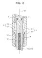
FIG 2 ] Enlarged partial cross-sectional view showing the structures of a flexible member, etc. - [
FIG 3 ] Enlarged partial cross-sectional view showing the structures of a sensor structure, etc. - [
FIG. 4 ] Partially sectioned front view showing a state in which the combustion pressure sensor is attached to an internal combustion engine. - [
FIG 5 ] Enlarged partial cross-sectional view showing the structures of a cap member, etc. in a second embodiment. - [
FIGS. 6A and 6B ] Views showing the structure of a combustion pressure sensor in a third embodiment, whereinFIG. 6A is a cross-sectional view, andFIG. 6B is a front view. - [
FIG 7 ] Enlarged partial cross-sectional view showing the layout of a sensor element, etc. in the third embodiment. - [
FIG. 8 ] Enlarged partial cross-sectional view showing the structures of a cap member, etc. in another embodiment. - [
FIG 9 ] Enlarged partial cross-sectional view showing the manner of fixing of a flexible member to a housing in another embodiment. - A first embodiment will now be described with reference to the drawings.
FIG 1 is a partially sectioned front view showing an example of a combustion pressure sensor having a function of heating the interior of a combustion chamber. - As shown in
FIG 1 , a combustion pressure sensor having a heating function (hereinafter referred to as a "combustion pressure sensor") 1 includes atubular housing 2; apressure transmission body 3 whose front end portion is exposed from the front end of thehousing 2; and asensor structure 4 for detecting combustion pressure. - The
housing 2 is composed of amain body portion 21 and acap member 22 each of which has a tubular shape and which are joined together. Thehousing 2 has anaxial hole 23 extending therethrough in the direction of an axis CL1. - The
main body portion 21 is formed of a predetermined metallic material. Themain body portion 21 has, on its outer circumferential surface, ascrew portion 24 to be screwed into a mounting hole of an internal combustion engine such as a diesel engine, and atool engagement portion 25 which has a hexagonal cross section and with which a tool such as a torque wrench is engaged. - The
cap member 22 is formed of a predetermined metallic material, and its rear end portion is joined to a front end portion of themain body portion 21. Thecap member 22 has apress contact portion 26, and a tubularcylindrical portion 27 extending rearward from thepress contact portion 26 along the axis CL1. Thepress contact portion 26 is formed to have a wall thickness (thickness in the radial direction) greater than that of thecylindrical portion 27, and has ataper surface 26a tapered frontward in the direction of the axis CL1. When thescrew portion 24 is screwed into a mounting hole HO of an internal combustion engine EN. thetaper surface 26a of thepress contact portion 26 is pressed against a tapered seat surface SE formed at the bottom end of the mounting hole HO, whereby sealing is established between the internal combustion engine EN and the combustion pressure sensor 1 (seeFIG 4 ). - The
pressure transmission body 3 is composed of a barlikeheat generation unit 31 and atubular sleeve 32 connected together in series. - The
heat generation unit 31 is configured such that aheat generation coil 34 and acontrol coil 35 are placed in atube 33 along with insulatingpowder 36 such as powder of magnesium oxide. - The
tube 33 is formed of a metallic material (e.g., Inconel, a stainless steel alloy, etc.) which contains iron (Fe) or nickel (Ni) as the main component, and has a closed front end portion. Thetube 33 has, on its rear end side, a press-fitlarge diameter portion 33a which is formed by means of a swaging process or the like and which has a relatively large outer diameter. Meanwhile, thetube 33 has, on its front end side, aheat generation portion 33b which is smaller in diameter than the press-fitlarge diameter portion 33a and in which theheat generation coil 34 is accommodated. - The
heat generation coil 34 and thecontrol coil 35 are connected together in series, and a front end portion of theheat generation coil 34 is joined to a front end portion of thetube 33. Theheat generation coil 34 is formed from a resistance heating wire which contains Fe (main component), chromium (Cr), aluminum (A1), etc. Meanwhile, thecontrol coil 35 is formed of a material which is greater in temperature coefficient of electrical resistivity than the material of theheat generation coil 34; for example, formed from a resistance heating wire made of a material whose main component is Co or Ni (e.g., cobalt (Co)-Ni-Fe alloy). Thus, thecontrol coil 35 increases its electrical resistance as a result of its own heat generation or as a result of receipt of heat generated by theheat generation coil 34, to thereby control the amount of electric power supplied to theheat generation coil 34. That is, at the beginning of energization, a relatively large amount of electric power is supplied to theheat generation coil 34, so that the temperature of theheat generation coil 34 increases sharply. Meanwhile, when the heat generation of theheat generation coil 34 proceeds, thecontrol coil 35 is heated by heat such as the heat generated by theheat generation coil 34, and the electrical resistance of thecontrol coil 35 increases. As a result, the amount of electric power supplied to theheat generation coil 34 decreases. Accordingly, theheat generation unit 31 has a temperature rising characteristic such that, after the rapid temperature rising at the beginning of energization, the supply of electric power is restricted by the action of thecontrol coil 35, whereby the temperature becomes saturated. That is, since thecontrol coil 35 is provided, it is possible to prevent excessive increase (overshoot) of the temperature of theheat generation coil 34 while enhancing the rapid temperature rising performance. - Notably, a predetermined external controller may be used so as to adjust the amount of electric power supplied to the
heat generation coil 34 to thereby control the heat generation of theheat generation coil 34. In such a case, thecontrol coil 35 can prevent an excessive temperature rising of theheat generation coil 34, which would otherwise occur when the external controller fails. That is, thecontrol coil 35 may be used so as to positively adjust the amount of electric power supplied to theheat generation coil 34, or may be used so as to prevent the supply of overcurrent to theheat generation coil 34, which would otherwise occur, for example, as a result of failure of the external controller. - The insulating
powder 36 is charged around theheat generation coil 34 and thecontrol coil 35 within thetube 33. Therefore, whereas the front end portion of theheat generation coil 34 is electrically connected to thetube 33, the outer circumferential surfaces of theheat generation coil 34 and thecontrol coil 35 are electrically insulated from the inner circumferential surface of thetube 33 by means of the insulatingpowder 36. - A
center rod 5 formed of a metal and extending in the direction of the axis CL1 is provided in theaxial hole 23. A front end portion of thecenter rod 5 is inserted into thetube 33, and is electrically connected to thecontrol coil 35. An electrically conductiveterminal fitting 6 is fixed to a rear end portion of thecenter rod 5. Electric power is supplied to theheat generation coil 34 via theterminal fitting 6 and thecenter rod 5. Notably, anannular rubber member 7 is provided between a rear end portion of thetube 33 and thecenter rod 5 so as to seal the interior of thetube 33. - As shown in
FIG 2 , the pressure transmission body 3 (the heat generation unit 31) is held by themain body portion 21 via a tubularflexible member 8 formed of a metal (e.g., SUS). Specifically, themain body portion 21 has atubular projection 28, which projects frontward, with respect to the direction of the axis CL1, from a front end portion of themain body portion 21. Theprojection 28 is press-fitted into a rear end portion of theflexible member 8. That is, the rear end portion of theflexible member 8 is fixed to thehousing 2 on the front end side of a portion of thehousing 2 located at the center between the rear end of thescrew portion 24 and thepress contact portion 26. Meanwhile, the press-fitlarge diameter portion 33a of thetube 33 is press-fitted into and is joined to a front end portion of theflexible member 8. Thus, thepressure transmission body 3 is held by themain body portion 21. - The
flexible member 8 has, at its generally central portion, abellows portion 81, which is displaceable through expanding and contracting itself along the direction of the axis CL1. Thus, theflexible member 8 can expand and contract along the direction of the axis CL1. When a pressure is applied to a front end portion of theheat generation unit 31, thebellows portion 81 of theflexible member 8 contracts, and, with this deformation, theheat generation unit 31 held by theflexible member 8 moves rearward in relation to thehousing 2. - Referring back to
FIG 1 , thesleeve 32 is formed of a predetermined metallic material, and is provided on the radially outer side of thecenter rod 5 such that a clearance is formed between thesleeve 32 and the inner circumferential surface of theaxial hole 23, and a clearance is formed between thesleeve 32 and the outer circumferential surface of thecenter rod 5. A rear end portion of theheat generation unit 31 is press-fitted into and joined to a front end portion of thesleeve 32. Therefore, when theheat generation unit 31 moves in relation to thehousing 2, thesleeve 32 also moves in relation to thehousing 2. - An annular insulating
rubber member 9 is inserted between a rear end portion of thesleeve 32 and thecenter rod 5. The insulatingrubber member 9 prevents deflective movement of a rear end portion of thecenter rod 5, which would otherwise occur because of vibration, and avoids contact between thecenter rod 5 and thesleeve 32. Anannular grove 37, which is centered at the axis CL1, is formed on an outer circumferential surface of thesleeve 32 at a generally central position along the axis CL1. An annular O-ring 10 is disposed in thegroove 37. The O-ring 10 is configured such that it comes into contact with both thesleeve 32 and themain body portion 21. Thus, it is possible to prevent thesleeve 32 from resonating as a result of operation of an internal combustion engine, and prevents thesleeve 32 from coming into contact with the wall surface of the axial hole of thehousing 2; i.e., prevents formation of a short circuit between thesleeve 32 and thehousing 2. - As shown in
FIG 3 , thesensor structure 4 is joined to the rear end of themain body portion 21. Thesensor structure 4 is composed of acasing 41 and various components disposed within thecasing 41, such as asensor element 42, adistortion member 43, and arelay member 44. - The
casing 41 assumes a cylindrical tubular shape, and has, at its rear end, a rear wall portion (upper wall portion) having a hole through which thecenter rod 5 can be passed. Atubular attachment portion 29 projecting from a rear end portion of themain body portion 21 is inserted into thecasing 41. In this state, thecasing 41 and theattachment portion 29 are joined together, whereby thesensor structure 4 is joined to themain body portion 21. - The
distortion member 43 provided within thecasing 41 assumes an annular shape, and has aninner wall portion 43a having an outer diameter approximately equal to that of thesleeve 32, anouter wall portion 43b in contact with the inner circumferential surface of thecasing 41, and a rear wall portion 43c connecting the twowall portions relay member 44 provided in thecasing 41 assumes a cylindrical tubular shape, and has arear wall portion 44c having a hole through which thecenter rod 5 can be passed. Therelay member 44 is placed on thedistortion member 43, and the outer circumferential surfaces of thedistortion member 43 and therelay member 44 are fixed to the inner circumferential surface of thecasing 41. A rear end portion of thesleeve 32 is joined to a front end portion of theinner wall portion 43a of thedistortion member 43. Accordingly, when thesleeve 32 moves relatively as a result of theheat generation unit 31 receiving a pressure, the rear wall portion 43c of thedistortion member 43 is pushed by thesleeve 32 and deforms. - The above-mentioned
sensor element 42 is disposed on the rear wall portion 43c of thedistortion member 43. Thesensor element 42 is composed of, for example, a known semiconductor stain gauge which includes piezoresistance elements formed on a semiconductor substrate such as a silicon substrate. The resistance of thesensor element 42 changes in accordance with the degree of deformation of the rear wall portion 43c of thedistortion member 43. Arelay substrate 45 is disposed on therear wall portion 44c of therelay member 44 facing the rear wall portion 43c of thedistortion member 43. Therelay substrate 45 is electrically connected to thesensor element 42 by means of wire boding or flexible cable (not shown), and has a function of converting the resistance of thesensor element 42 to a voltage, and amplifying the voltage. The amplified voltage is output to an external circuit such as an ECU (not shown) via acable 46 connected to therelay member 44. - In the present embodiment, whereas the
cap member 22 is formed of a material having a relatively low Young's modulus (e.g., a titanium alloy, aluminum, or the like), the housing is formed of a material having a relatively high Young's modulus (e.g., carbon steel, SUS, or the like). That is, the Young's modulus of thecap member 22 is made smaller than that of themain body portion 21. - A method of manufacturing the combustion pressure sensor I having the above-described configuration will be described. Notably, portions which are not specifically described are manufactured by conventionally known methods.
- First, the
heat generation unit 31 is manufactured. Specifically, a resistance heating wire containing Fe as the main component is formed into a coil shape so as to obtain theheat generation coil 34, and a resistance heating wire made of a Co alloy or the like is formed into a coil shape so as to obtain thecontrol coil 35. A rear end portion of theheat generation coil 34 and a front end portion of thecontrol coil 35 are joined together. Subsequently, the front end of thecenter rod 5 and theheat generation coil 34 and thecontrol coil 35 united with thecenter rod 5 are placed in thetube 33 whose front end has not yet been closed. By means of arc welding, the front end portion of thetube 33 is closed, and a front end portion of theheat generation coil 34 is joined to the front end portion of thetube 33. After that, the insulatingpowder 36 is charged into thetube 33, and swaging is performed on thetube 33. As a result, the fit-inlarge diameter portion 33a and theheat generation portion 33b are formed on thetube 33, and theheat generation unit 31 united with thecenter rod 5 is obtained. - Furthermore, the
main body 21, which has theaxial hole 23, thescrew portion 24, etc., is manufactured by means of performing forging, rolling, or a like process on a predetermined alloy. Moreover, an alloy whose Young's modulus is smaller than that of the alloy that constitutes themain body portion 21 is prepared, and forging or a like process is performed on the prepared alloy, to thereby manufacture thecap member 22. In addition, forging or a like process is performed on a predetermined alloy, to thereby obtain thesleeve 32. - Subsequently, after the length of the
center rod 5 is adjusted by cutting a rear end portion of thecenter rod 5, thesleeve 32 is disposed on the outer circumferential side of thecenter rod 5. Then, the front end portion of thesleeve 32 and the rear end portion of the heat generation unit 31 (the tube 33) are joined together by means of laser welding. - The insulating
rubber member 9 is inserted between the rear end portion of thesleeve 32 and thecenter rod 5 after the joining of thesleeve 32 and theheat generation unit 31, and the rear end portion of thesleeve 32 and the distortion member 43 (theinner wall portion 43a) of thesensor structure 4 are joined together. After that, the O-ring 10 is disposed on the outer circumference of thesleeve 32, and theheat generation unit 31 and thesleeve 32 are inserted into themain body portion 21 from its rear end opening. Subsequently, thecasing 41 of thesensor structure 4 is joined to the rear end portion of themain body portion 21. Further, theterminal fitting 6 is press-fitted onto and joined to the rear end portion of thecenter rod 5 projecting rearward from thesensor structure 4. - Next, the above-described
heat generation unit 31 is passed through theflexible member 8, which is manufactured in advance. In a state in which theprojection 28 of themain body portion 21 is fitted into the rear end portion of theflexible member 8, a laser beam is applied to the outer circumferential surface of theflexible member 8 so as to join the rear end portion of theflexible member 8 and themain body portion 21. Moreover, the heat generation unit 31 (the tube 33) is joined to the front end portion of theflexible member 8. - Finally, in a state in which the
heat generation unit 31 is passed through thecap member 22, a laser beam is applied along the outer edge of a contact surface between the front end portion of themain body portion 21 and the rear end portion of thecap member 22. Thus, thecap member 22 and themain body portion 21 are joined together, whereby the above-describedcombustion pressure sensor 1 is obtained. - As having being described in detail, according to the present embodiment, the Young's modulus of the
cap member 22 is made smaller than that of themain body portion 21. Therefore, when a force along the direction of the axis CL1 is applied, thecap member 22 contracts more easily than does themain body portion 21. Accordingly, when thecombustion pressure sensor 1 is attached to the internal combustion engine EN, thecap member 22, which does not affect thepressure transmission body 3 even when it deforms compressively, is caused to deform in a greater amount, and the amount of deformation of themain body portion 21, which affects thepressure transmission body 3, can be made relatively small. As a result, the force along the axial direction which acts on thepressure transmission body 3 as a result of deformation of themain body portion 21 can be reduced effectively, and the detection accuracy of combustion pressure can be improved. - Moreover, the rear end portion of the
flexible member 8 is fixed to thehousing 2 on the front end side of a portion of thehousing 2 located at the center between the rear end of thescrew portion 24 and thepress contact portion 26. Therefore, the length of theflexible member 8, as measured along the axis CL1, can be made relatively short, whereby thepressure transmission body 3 can be held in a more stable state. As a result, the detection accuracy of combustion pressure can be improved further. - Next, a second embodiment will be described. In the following description, a structural feature of the second embodiment which differs from those of the first embodiment will be mainly described.
- As shown in
FIG 5 , acombustion pressure sensor 101 according to the second embodiment differs from the first embodiment in the structure of acap member 122. Specifically, thecap member 122 includes apress contact portion 126 having a relatively large wall thickness, and acylindrical portion 127 extending along the axis CL1 from the rear end of thepress contact portion 126. An annular groove centered at the axis CL1 is formed on the outer circumferential surface of thecylindrical portion 127, whereby athin wall portion 127a is provided. In order to maintain a required mechanical strength, thecap member 122 is formed of the same metallic material (e.g., carbon steel, SUS or the like) as themain body portion 21. - According to the above-described second embodiment, the
cylindrical portion 127 of thecap member 122 has thethin wall portion 127a. Therefore, when thecombustion pressure sensor 101 is attached to the internal combustion engine EN, thecap member 122 can be caused to deform in a greater amount, and the amount of deformation of themain body portion 21 can be made relatively small. Thus, the force along the axial direction which acts on thepressure transmission body 3 as a result of deformation of themain body portion 21 can be reduced, and the detection accuracy of combustion pressure can be improved. - Next, a third embodiment will be described. In the following description, a structural feature of the third embodiment which differs from those of the first and second embodiments will be mainly described. As shown in
FIGS. 6A and 6B , in acombustion pressure sensor 201 according to the third embodiment, asensor element 242 is provided within ahousing 202, and is fixed indirectly to a portion of thehousing 202 located between the front end of ascrew portion 224 and the front end of apress contact portion 226. Specifically, as shown inFIG 7 , thesensor element 242 is fixed to thehousing 202 via atubular sleeve 251 having a portion disposed between and fixed to amain body portion 221 of thehousing 202 and acap member 222, and apedestal 252 disposed within a rear end portion of thesleeve 251. Astopper member 253 fitted into thesleeve 251 restricts at least rearward movement of thepedestal 252. - The
cap member 222 includes afirst member 261 having thepress contact portion 226, and asecond member 262 joined to the rear end of thefirst member 261. Atubular projection 271 is provided at the front end of thesecond member 262. Theprojection 271 has an outer diameter smaller than the inner diameter of thefirst member 261, and is separated from thefirst member 261 in the radial direction. Aflexible member 208 is fixed to the second member 262 (the housing 202) via theprojection 271. That is, one end of theflexible member 208 is fixed to thehousing 202 at a position between aportion P 1 of thehousing 202 to which thesensor element 242 is fixed and thepress contact portion 226. - In addition, a portion of the
second member 262 located between themain body portion 221 and thefirst member 261 is greater in wall thickness than at least one of (in the present embodiment, both) a portion of themain body portion 221 between its front end and thescrew portion 224, and a cylindrical portion 227 (a cylindrical portion extending rearward from the press contact portion 226) of thefirst member 261. Notably, the present embodiment may be modified such that, whereas thefirst member 261 is formed of a material having a relatively low Young's modulus (e.g., a titanium alloy, aluminum, or the like), thesecond member 262 is formed of a material having a relatively high Young's modulus (e.g., carbon steel, SUS, or the like). - In the third embodiment, as shown in
FIG. 6A , apressure transmission body 203 is constituted by aceramic heater 233 having atubular base 231 formed of insulating ceramic, and aheating element 232 formed of electrically conductive ceramic and provided within thebase 231; and disk-shapedintermediate members ceramic heater 233. The outer surface of the pressure transmission body 203 (the ceramic heater 233) is fixed to the other end of theflexible member 208. Notably, in the present embodiment, electric power is supplied to theceramic heater 233 via atubular center rod 281 provided inside thehousing 202. Further, signals from thesensor element 242 are output to the outside via a plurality ofsignal lines 282 provided inside thecenter rod 281. - The
combustion pressure sensor 201 according to the third embodiment is configured to satisfy at least one of the following expressions (1) and (2). That is, when a force along the axis CL1 is applied to a portion of thehousing 202 between the front end of thescrew portion 224 and thepress contact portion 226 as shown inFIG 7 , a portion of thehousing 202 located between aportion P 1 to which thesensor element 242 is fixed and a portion P2 to which theflexible member 208 is fixed is compressed by a compression amount X, a portion of thehousing 202 between the portion P2 to which theflexible member 208 is fixed and the front end of thepress contact portion 226 is compressed by a compression amount Y, and a portion of thehousing 202 between the front end of thescrew portion 224 and theportion P 1 to which thesensor element 242 is fixed is compressed by a compression amount Z. Thecombustion pressure sensor 201 is configured to satisfy at least one of the following expressions (1) and (2).

- According to the above-described third embodiment, a portion of the
housing 202 which affects thepressure transmission body 203 through compressive deformation thereof (a portion of thehousing 202 between theportion P 1 and the portion P2) can be shortened further. Therefore, the force along the axial direction which acts on thepressure transmission body 203 when thecombustion pressure sensor 201 is attached to an internal combustion engine can be reduced effectively. - Moreover, when the
combustion pressure sensor 201 is attached to an internal combustion engine, a portion of thehousing 202 which does not affect thepressure transmission body 203 even when it deforms compressively (a portion of thehousing 202 between the portion P2 and the front end of thepress contact portion 226 and a portion of thehousing 202 between the front end of thescrew portion 224 and the portion P1) contracts to a greater degree as compared with a portion of thehousing 202 which affects thepressure transmission body 203 through compressive deformation thereof (a portion between theportions P 1 and P2). Therefore, the force along the axial direction which acts on thepressure transmission body 203 when thecombustion pressure sensor 201 is attached to an internal combustion engine can be reduced further, and the detection accuracy of combustion pressure can be improved further. - Notably, the present invention is not limited to the details of the above-described embodiments, and may be practiced as follows. Needless to say, other applications and modifications which are not exemplified below are also possible.
-
- (a) In the above-described embodiments, the Young's modulus of the
cap member 22 is made smaller than that of themain body portion 21, or thethin wall portion 127a is provided on the outer circumferential surface of thecylindrical portion 127. Thus, when a force along the axis CL1 is applied to thehousing 2, the compression amount per unit length along the axis CL1 of themain body portion 21 becomes smaller than that of thecap member 22. Further, when a force along the axis CL1 is applied to thehousing 2, the compression amount of a portion of thehousing 2 between the portion to which theflexible member 8 is fixed and the front end of thescrew portion 24 becomes smaller than the compression amount of a portion of thehousing 2 between the portion to which theflexible member 8 is fixed and the front end of thepress contact portion 26. However, the method of realizing such a configuration is not limited to the methods of the above-described embodiments. For example, the above-described configuration can be realized by means of providing an annular curved portion (centered at the axis CL1) on thecylindrical portion 27 of thecap member 22, while maintaining the constant wall thickness of thecylindrical portion 27. -
- (b) In the above-described second embodiment, the
thin wall portion 127a is provided on the outer circumferential surface of thecylindrical portion 127. However, as shown inFIG 8 , athin wall portion 127b may be provided on the inner circumferential surface of thecylindrical portion 127. In this case as well, actions and effects similar to those of the second embodiment can be attained. -
- (c) In the above-described embodiments, the
pressure transmission body 3 includes theheat generation unit 31. However, the combustion pressure sensor may be configured without use of the heat generation unit 31 (that is, by eliminating the heating function). -
- (d) In the above-described embodiments, a semiconductor stain gauge which includes piezoresistance elements formed on a semiconductor substrate is used as the
sensor element 42. However, thesensor element 42 is not limited thereto, and a piezoelectric element or the like may be used. -
- (e) In the above-described embodiments, the
pressure transmission body 3 is held by theflexible member 8 having thebellows portion 81. However, the structure of theflexible member 8 is not limited thereto. For example, a member which has a tubular portion and a flange portion extending from an end portion of the tubular portion in the radially outward direction and in which the flange portion can deform in relation to the tubular portion, or a tubular member (so-called membrane) which can displace along the direction of the axis through curving in the radial direction may be used as the flexible member. Notably, when a membrane is used, thepressure transmission body 3 is fixed to the tubular portion (the front end of the tubular member), and the flange portion (the rear end of the tubular member) is fixed to themain body portion 21. -
- (f) In the above-described third embodiment, the
flexible member 208 is fixed indirectly to thesecond member 262 of thehousing 202. However, the third embodiment may be modified as shown inFIG 9 . Specifically, a rear end portion of aflexible member 308 is formed into a flange, and the flange is sandwiched between and is joined to first andsecond members flexible member 308 is fixed to ahousing 302. Notably, in this case, the "portion of the housing to which the flexible member is fixed" refers to the frontmost portion P3 of an area in which thehousing 302 and theflexible member 308 are fixed together. That is, the portion P3 is a portion of theflexible member 308 for relatively moving theceramic heater 333 rearward, and is located between atubular portion 309 which does not move even when a combustion pressure acts thereon, and abellows portion 381 which is separated from thefirst member 361 in the radial direction and deforms when a combustion pressure acts thereon. Further, the structure shown inFIG 9 may be modified such that thesecond member 362 is removed, and the flange portion of theflexible member 308 is joined directly to the front end portion of thesleeve 251 formed into a flange shape. -
- (g) The shape, etc. of the
combustion pressure sensor 1 are not limited to those of the above-described embodiments. For example, thetube 33 may be modified such that theheat generation portion 33b having a small diameter is omitted, and thetube 33 has a straight shape; i.e., has an approximately constant outer diameter up to the front end of thetube 33. No particular limitation is imposed on the position of the sensor element. For example, the sensor element may be provided within themain body portion 21. -
- (h) In the above-described embodiments, the combustion pressure sensor I has the
control coil 35. However, thecontrol coil 35 may be omitted. In such a case, the rear end of theheat generation coil 34 is joined directly to thecenter rod 5. -
- 1, 101: combustion pressure sensor
- 2: housing
- 3: pressure transmission body
- 8: flexible member
- 21: main body portion
- 22, 122: cap member
- 24: screw portion
- 26, 126: press contact portion
- 27, 127: cylindrical portion
- 42: sensor element
- 127a, 127b: thin wall portion
- CL1: axis
- EN: internal combustion engine
- HO: mounting hole
Claims (7)
- A combustion pressure sensor comprising:a tubular housing having an axial hole extending in a direction of an axis;a flexible member disposed within the axial hole and fixed at one end to the housing, the flexible member being displaceable and contractable along the direction of the axis;a rod-shaped pressure transmission body inserted into the axial hole and fixed, through its outer circumferential surface, to the other end of the flexible member, the pressure transmission body having a front end portion exposed to the outside; anda sensor element fixed directly or indirectly to the housing and outputting a signal on the basis of a pressure applied thereto from the pressure transmission body, whereinthe housing includes a main body portion having, on its outer circumferential surface, a screw portion for screw engagement with a mounting hole of an internal combustion engine, and a cap member joined to a front end portion of the main body portion and having a press contact portion which is press-contacted with the internal combustion engine when the screw portion is screwed into the mounting hole of the internal combustion engine; andthe one end of the flexible member is fixed to the main body portion,the combustion pressure sensor being characterized in that a relation A < B is satisfied where A represents an amount of compression per unit length along the axis of the main body portion and B represents an amount of compression per unit length along the axis of the cap member, the compression amounts being measured when a force along the axis is applied to the housing.
- A combustion pressure sensor comprising:a tubular housing having an axial hole extending in a direction of an axis;a flexible member disposed within the axial hole and fixed at one end to the housing, the flexible member being displaceable and contractable along the direction of the axis;a rod-shaped pressure transmission body inserted into the axial hole and fixed, through its outer circumferential surface, to the other end of the flexible member, the pressure transmission body having a front end portion exposed to the outside; anda sensor element fixed directly or indirectly to the housing and outputting a signal on the basis of a pressure applied thereto from the pressure transmission body, whereinthe housing has a screw portion for screw engagement with a mounting hole of an internal combustion engine, and a press contact portion which is press-contacted with the internal combustion engine when the screw portion is screwed into the mounting hole of the internal combustion engine,the combustion pressure sensor being characterized in thatthe one end of the flexible member is fixed to the housing on the front end side of a portion of the housing located at the center between a rear end of the screw portion and the press contact portion;a region where the flexible member and the pressure transmission body are fixed together is located within the housing; anda relation A < B is satisfied where A represents an amount of compression of a portion of the housing between a portion of the housing to which the flexible member is fixed and a front end of the screw portion, and B represents an amount of compression of a portion of the housing between the portion of the housing to which the flexible member is fixed and a front end of the press contact portion, the compression amounts being measured when a force along the axis is applied to a portion of the housing located between the front end of the screw portion and the press contact portion.
- A combustion pressure sensor comprising:a tubular housing having an axial hole extending in a direction of an axis;a flexible member disposed within the axial hole and fixed at one end to the housing, the flexible member being displaceable and contractable along the direction of the axis;a rod-shaped pressure transmission body inserted into the axial hole and fixed, through its outer circumferential surface, to the other end of the flexible member, the pressure transmission body having a front end portion exposed to the outside; anda sensor element fixed directly or indirectly to the housing and outputting a signal on the basis of a pressure applied thereto from the pressure transmission body, whereinthe housing includes a main body portion having, on its outer circumferential surface, a screw portion for screw engagement with a mounting hole of an internal combustion engine, and a cap member joined to a front end portion of the main body portion and having a press contact portion which is press-contacted with the internal combustion engine when the screw portion is screwed into the mounting hole of the internal combustion engine; andthe one end of the flexible member is fixed to the main body portion,the combustion pressure sensor being characterized in that the cap member has a Young's modulus smaller than that of the main body portion.
- A combustion pressure sensor comprising:a tubular housing having an axial hole extending in a direction of an axis;a flexible member disposed within the axial hole and fixed at one end to the housing, the flexible member being displaceable and contractable along the direction of the axis;a rod-shaped pressure transmission body inserted into the axial hole and fixed, through its outer circumferential surface, to the other end of the flexible member, the pressure transmission body having a front end portion exposed to the outside; anda sensor element fixed directly or indirectly to the housing and outputting a signal on the basis of a pressure applied thereto from the pressure transmission body, whereinthe housing includes a main body portion having, on its outer circumferential surface, a screw portion for screw engagement with a mounting hole of an internal combustion engine, and a cap member joined to a front end portion of the main body portion and having a press contact portion which is press-contacted with the internal combustion engine when the screw portion is screwed into the mounting hole of the internal combustion engine; andthe one end of the flexible member is fixed to the main body portion,the combustion pressure sensor being characterized in that the cap member has a cylindrical tubular portion extending along the axis from a rear end of the press contact portion; andthe cylindrical portion has, on its inner circumferential surface or its outer circumferential surface, an annular groove which is centered at the axis and which forms a thin wall portion.
- A combustion pressure sensor comprising:a tubular housing having an axial hole extending in a direction of an axis;a flexible member disposed within the axial hole and fixed at one end to the housing, the flexible member being displaceable and contractable along the direction of the axis;a rod-shaped pressure transmission body inserted into the axial hole and fixed, through its outer circumferential surface, to the other end of the flexible member), the pressure transmission body having a front end portion exposed to the outside; anda sensor element fixed directly or indirectly to the housing and outputting a signal on the basis of a pressure applied thereto from the pressure transmission body, whereinthe housing has a screw portion for screw engagement with a mounting hole of an internal combustion engine, and a press contact portion which is press-contacted with the internal combustion engine when the screw portion is screwed into the mounting hole of the internal combustion engine,the combustion pressure sensor being characterized in thatthe sensor element is fixed directly or indirectly to a portion of the housing located between a front end of the screw portion and a front end of the press contact portion;the flexible member is fixed to a portion of the housing located between the portion of the housing to which the sensor element is fixed and the press contact portion; anda relation X < Y is satisfied where X represents an amount of compression of a portion of the housing between the portion of the housing to which the sensor element is fixed and the portion of the housing to which the flexible member is fixed, and Y represents an amount of compression of a portion of the housing between the portion of the housing to which the flexible member is fixed and a front end of the press contact portion, the compression amounts being measured when a force along the axis is applied to a portion of the housing located between the front end of the screw portion and the press contact portion.
- A combustion pressure sensor comprising:a tubular housing having an axial hole extending in a direction of an axis;a flexible member disposed within the axial hole and fixed at one end to the housing, the flexible member being displaceable and contractable along the direction of the axis;a rod-shaped pressure transmission body inserted into the axial hole and fixed, through its outer circumferential surface, to the other end of the flexible member, the pressure transmission body having a front end portion exposed to the outside; anda sensor element fixed directly or indirectly to the housing and outputting a signal on the basis of a pressure applied thereto from the pressure transmission body, whereinthe housing has a screw portion for screw engagement with a mounting hole of an internal combustion engine, and a press contact portion which is press-contacted with the internal combustion engine when the screw portion is screwed into the mounting hole of the internal combustion engine,the combustion pressure sensor being characterized in thatthe sensor element is fixed directly or indirectly to a portion of the housing located between a front end of the screw portion and a front end of the press contact portion;the flexible member is fixed to a portion of the housing located between the portion of the housing to which the sensor element is fixed and the press contact portion; anda relation X < Z is satisfied where X represents an amount of compression of a portion of the housing between the portion of the housing to which the sensor element is fixed and the portion of the housing to which the flexible member is fixed, and Z represents an amount of compression of a portion of the housing between a front end of the screw portion and the portion of the housing to which the sensor element is fixed, the compression amounts being measured when a force along the axis is applied to a portion of the housing located between the front end of the screw portion and the press contact portion.
- A combustion pressure sensor according to any one of claims 1 to 6, wherein at least a portion of the exposed front end portion of the pressure transmission body is a heat generation unit.
Applications Claiming Priority (2)
| Application Number | Priority Date | Filing Date | Title |
|---|---|---|---|
| JP2010011714 | 2010-01-22 | ||
| JP2010256577A JP5654846B2 (en) | 2010-01-22 | 2010-11-17 | Combustion pressure sensor |
Publications (2)
| Publication Number | Publication Date |
|---|---|
| EP2348298A1 true EP2348298A1 (en) | 2011-07-27 |
| EP2348298B1 EP2348298B1 (en) | 2017-10-25 |
Family
ID=43827461
Family Applications (1)
| Application Number | Title | Priority Date | Filing Date |
|---|---|---|---|
| EP11151011.1A Not-in-force EP2348298B1 (en) | 2010-01-22 | 2011-01-14 | Combustion pressure sensor |
Country Status (3)
| Country | Link |
|---|---|
| US (2) | US8567237B2 (en) |
| EP (1) | EP2348298B1 (en) |
| JP (1) | JP5654846B2 (en) |
Cited By (1)
| Publication number | Priority date | Publication date | Assignee | Title |
|---|---|---|---|---|
| WO2016155995A1 (en) * | 2015-03-30 | 2016-10-06 | Robert Bosch Gmbh | Combustion-chamber pressure sensor, internal combustion engine, and method for measuring a combustion chamber pressure in a combustion chamber of an internal combustion engine |
Families Citing this family (13)
| Publication number | Priority date | Publication date | Assignee | Title |
|---|---|---|---|---|
| KR101491945B1 (en) * | 2011-02-25 | 2015-02-10 | 니혼도꾸슈도교 가부시키가이샤 | Glow plug with combustion pressure sensor |
| JP5854638B2 (en) * | 2011-05-19 | 2016-02-09 | 株式会社ミクニ | Glow plug |
| US8806925B2 (en) * | 2011-11-23 | 2014-08-19 | S3C, Inc. | Mechanical packaging technique of attaching MEMS and flex circuit |
| WO2013164909A1 (en) * | 2012-05-02 | 2013-11-07 | 日本特殊陶業株式会社 | Glow plug equipped with pressure sensor |
| JP6151067B2 (en) * | 2012-06-28 | 2017-06-21 | 日本特殊陶業株式会社 | Glow plug with pressure sensor |
| JP1516097S (en) * | 2014-03-05 | 2015-01-26 | ||
| JP1516096S (en) * | 2014-03-05 | 2015-01-26 | ||
| US10253982B2 (en) * | 2014-12-22 | 2019-04-09 | Ngk Spark Plug Co., Ltd. | Glow plug with pressure sensor |
| JP6561780B2 (en) * | 2015-11-06 | 2019-08-21 | 株式会社デンソー | Combustion pressure sensor |
| DE102016114929B4 (en) * | 2016-08-11 | 2018-05-09 | Borgwarner Ludwigsburg Gmbh | pressure measuring glow |
| CN106768591B (en) * | 2016-12-21 | 2019-08-30 | 中国航发长春控制科技有限公司 | A kind of single-point survey pressure detector probe device resistant to high temperature |
| JP7136915B2 (en) * | 2018-10-31 | 2022-09-13 | 京セラ株式会社 | heater |
| CN115219100B (en) * | 2022-09-21 | 2022-11-25 | 中国空气动力研究与发展中心空天技术研究所 | Total pressure measuring structure of combustion heater |
Citations (2)
| Publication number | Priority date | Publication date | Assignee | Title |
|---|---|---|---|---|
| US20010015402A1 (en) * | 1999-12-24 | 2001-08-23 | Hiroyuki Murai | Installation structure of engine component with combustion pressure sensor in engine |
| JP2006084468A (en) | 2004-09-15 | 2006-03-30 | Beru Ag | Pressure measuring glow plug |
Family Cites Families (11)
| Publication number | Priority date | Publication date | Assignee | Title |
|---|---|---|---|---|
| JP3911930B2 (en) * | 1999-10-28 | 2007-05-09 | 株式会社デンソー | Glow plug with combustion pressure sensor |
| JP4003363B2 (en) * | 1999-12-24 | 2007-11-07 | 株式会社デンソー | Combustion pressure sensor structure |
| DE10343521A1 (en) | 2003-09-19 | 2005-04-21 | Beru Ag | Pressure measuring glow plug for a diesel engine |
| US6948372B2 (en) * | 2004-01-08 | 2005-09-27 | Delphi Technologies, Inc. | Method of connection to a spark plug pressure sensor |
| JP2006300046A (en) * | 2004-08-05 | 2006-11-02 | Ngk Spark Plug Co Ltd | Glow plug with combustion pressure detecting function |
| JP4316474B2 (en) * | 2004-11-02 | 2009-08-19 | 株式会社デンソー | Combustion chamber pressure detector |
| JP2007085578A (en) * | 2005-09-20 | 2007-04-05 | Ngk Spark Plug Co Ltd | Glow plug with combustion pressure sensor |
| JP2007309916A (en) * | 2006-04-20 | 2007-11-29 | Denso Corp | Combustion pressure sensor |
| JP2008020176A (en) * | 2006-06-14 | 2008-01-31 | Ngk Spark Plug Co Ltd | Glow plug with built-in sensor |
| JP2008002809A (en) * | 2006-06-20 | 2008-01-10 | Denso Corp | Combustion pressure sensor |
| EP2138820B1 (en) | 2008-06-25 | 2016-09-21 | Sensata Technologies, Inc. | A piezoresistive pressure-measuring plug for a combustion engine |
-
2010
- 2010-11-17 JP JP2010256577A patent/JP5654846B2/en not_active Expired - Fee Related
-
2011
- 2011-01-14 EP EP11151011.1A patent/EP2348298B1/en not_active Not-in-force
- 2011-01-20 US US13/010,370 patent/US8567237B2/en active Active
-
2013
- 2013-08-19 US US13/970,360 patent/US9366594B2/en active Active
Patent Citations (2)
| Publication number | Priority date | Publication date | Assignee | Title |
|---|---|---|---|---|
| US20010015402A1 (en) * | 1999-12-24 | 2001-08-23 | Hiroyuki Murai | Installation structure of engine component with combustion pressure sensor in engine |
| JP2006084468A (en) | 2004-09-15 | 2006-03-30 | Beru Ag | Pressure measuring glow plug |
Cited By (1)
| Publication number | Priority date | Publication date | Assignee | Title |
|---|---|---|---|---|
| WO2016155995A1 (en) * | 2015-03-30 | 2016-10-06 | Robert Bosch Gmbh | Combustion-chamber pressure sensor, internal combustion engine, and method for measuring a combustion chamber pressure in a combustion chamber of an internal combustion engine |
Also Published As
| Publication number | Publication date |
|---|---|
| US20130333456A1 (en) | 2013-12-19 |
| EP2348298B1 (en) | 2017-10-25 |
| JP2011169887A (en) | 2011-09-01 |
| JP5654846B2 (en) | 2015-01-14 |
| US20110271748A1 (en) | 2011-11-10 |
| US8567237B2 (en) | 2013-10-29 |
| US9366594B2 (en) | 2016-06-14 |
Similar Documents
| Publication | Publication Date | Title |
|---|---|---|
| EP2348298B1 (en) | Combustion pressure sensor | |
| EP2105671B1 (en) | Glow plug | |
| EP2444786B1 (en) | A pressure measuring glow plug for a combustion engine | |
| US9347854B2 (en) | Glow plug with pressure sensor | |
| JP5797486B2 (en) | Glow plug with combustion pressure detection sensor | |
| WO2013099226A1 (en) | Ceramic glow plug equipped with pressure sensor | |
| KR101614625B1 (en) | Glow plug equipped with pressure sensor | |
| WO2010134320A1 (en) | Combustion pressure sensor and glowplug fitted with combustion pressure sensor | |
| JP6214932B2 (en) | Glow plug with pressure sensor | |
| JP6166093B2 (en) | Glow plug with pressure sensor | |
| JP2007078330A (en) | Glow plug with combustion pressure sensor | |
| JP2007085577A (en) | Glow plug with combustion pressure sensor | |
| US20160061683A1 (en) | Pressure sensor | |
| JP2006336918A (en) | Glow plug with combustion pressure sensor | |
| JP2007085578A (en) | Glow plug with combustion pressure sensor | |
| EP3247942B1 (en) | Glow plug including a load sensor and a welded flexible distal membrane having a transversal flexible collar | |
| JP2011149846A (en) | Pressure sensor | |
| JP2011149845A (en) | Combustion pressure sensor, and mounting structure of the same | |
| JP2020106512A (en) | In-cylinder pressure sensor | |
| JP5575291B2 (en) | Glow plug | |
| JP2018128274A (en) | Pressure sensor with heater | |
| JP2018136286A (en) | Combustion pressure sensor | |
| JP2014206352A (en) | Glow plug with combustion pressure sensor and manufacturing method of the same | |
| JP2014206353A (en) | Manufacturing method of glow plug with combustion pressure sensor |
Legal Events
| Date | Code | Title | Description |
|---|---|---|---|
| PUAI | Public reference made under article 153(3) epc to a published international application that has entered the european phase |
Free format text: ORIGINAL CODE: 0009012 |
|
| AK | Designated contracting states |
Kind code of ref document: A1 Designated state(s): AL AT BE BG CH CY CZ DE DK EE ES FI FR GB GR HR HU IE IS IT LI LT LU LV MC MK MT NL NO PL PT RO RS SE SI SK SM TR |
|
| AX | Request for extension of the european patent |
Extension state: BA ME |
|
| 17P | Request for examination filed |
Effective date: 20120126 |
|
| RAP1 | Party data changed (applicant data changed or rights of an application transferred) |
Owner name: NGK SPARK PLUG CO., LTD. |
|
| RIC1 | Information provided on ipc code assigned before grant |
Ipc: G01L 23/22 20060101ALI20170217BHEP Ipc: G01L 23/08 20060101AFI20170217BHEP |
|
| GRAP | Despatch of communication of intention to grant a patent |
Free format text: ORIGINAL CODE: EPIDOSNIGR1 |
|
| INTG | Intention to grant announced |
Effective date: 20170511 |
|
| GRAS | Grant fee paid |
Free format text: ORIGINAL CODE: EPIDOSNIGR3 |
|
| GRAA | (expected) grant |
Free format text: ORIGINAL CODE: 0009210 |
|
| AK | Designated contracting states |
Kind code of ref document: B1 Designated state(s): AL AT BE BG CH CY CZ DE DK EE ES FI FR GB GR HR HU IE IS IT LI LT LU LV MC MK MT NL NO PL PT RO RS SE SI SK SM TR |
|
| REG | Reference to a national code |
Ref country code: GB Ref legal event code: FG4D |
|
| REG | Reference to a national code |
Ref country code: CH Ref legal event code: EP |
|
| REG | Reference to a national code |
Ref country code: AT Ref legal event code: REF Ref document number: 940359 Country of ref document: AT Kind code of ref document: T Effective date: 20171115 |
|
| REG | Reference to a national code |
Ref country code: IE Ref legal event code: FG4D |
|
| REG | Reference to a national code |
Ref country code: DE Ref legal event code: R096 Ref document number: 602011042622 Country of ref document: DE |
|
| REG | Reference to a national code |
Ref country code: FR Ref legal event code: PLFP Year of fee payment: 8 |
|
| REG | Reference to a national code |
Ref country code: NL Ref legal event code: MP Effective date: 20171025 |
|
| REG | Reference to a national code |
Ref country code: LT Ref legal event code: MG4D |
|
| REG | Reference to a national code |
Ref country code: AT Ref legal event code: MK05 Ref document number: 940359 Country of ref document: AT Kind code of ref document: T Effective date: 20171025 |
|
| PG25 | Lapsed in a contracting state [announced via postgrant information from national office to epo] |
Ref country code: NL Free format text: LAPSE BECAUSE OF FAILURE TO SUBMIT A TRANSLATION OF THE DESCRIPTION OR TO PAY THE FEE WITHIN THE PRESCRIBED TIME-LIMIT Effective date: 20171025 |
|
| PG25 | Lapsed in a contracting state [announced via postgrant information from national office to epo] |
Ref country code: FI Free format text: LAPSE BECAUSE OF FAILURE TO SUBMIT A TRANSLATION OF THE DESCRIPTION OR TO PAY THE FEE WITHIN THE PRESCRIBED TIME-LIMIT Effective date: 20171025 Ref country code: SE Free format text: LAPSE BECAUSE OF FAILURE TO SUBMIT A TRANSLATION OF THE DESCRIPTION OR TO PAY THE FEE WITHIN THE PRESCRIBED TIME-LIMIT Effective date: 20171025 Ref country code: NO Free format text: LAPSE BECAUSE OF FAILURE TO SUBMIT A TRANSLATION OF THE DESCRIPTION OR TO PAY THE FEE WITHIN THE PRESCRIBED TIME-LIMIT Effective date: 20180125 Ref country code: ES Free format text: LAPSE BECAUSE OF FAILURE TO SUBMIT A TRANSLATION OF THE DESCRIPTION OR TO PAY THE FEE WITHIN THE PRESCRIBED TIME-LIMIT Effective date: 20171025 Ref country code: LT Free format text: LAPSE BECAUSE OF FAILURE TO SUBMIT A TRANSLATION OF THE DESCRIPTION OR TO PAY THE FEE WITHIN THE PRESCRIBED TIME-LIMIT Effective date: 20171025 |
|
| PG25 | Lapsed in a contracting state [announced via postgrant information from national office to epo] |
Ref country code: HR Free format text: LAPSE BECAUSE OF FAILURE TO SUBMIT A TRANSLATION OF THE DESCRIPTION OR TO PAY THE FEE WITHIN THE PRESCRIBED TIME-LIMIT Effective date: 20171025 Ref country code: AT Free format text: LAPSE BECAUSE OF FAILURE TO SUBMIT A TRANSLATION OF THE DESCRIPTION OR TO PAY THE FEE WITHIN THE PRESCRIBED TIME-LIMIT Effective date: 20171025 Ref country code: LV Free format text: LAPSE BECAUSE OF FAILURE TO SUBMIT A TRANSLATION OF THE DESCRIPTION OR TO PAY THE FEE WITHIN THE PRESCRIBED TIME-LIMIT Effective date: 20171025 Ref country code: BG Free format text: LAPSE BECAUSE OF FAILURE TO SUBMIT A TRANSLATION OF THE DESCRIPTION OR TO PAY THE FEE WITHIN THE PRESCRIBED TIME-LIMIT Effective date: 20180125 Ref country code: IS Free format text: LAPSE BECAUSE OF FAILURE TO SUBMIT A TRANSLATION OF THE DESCRIPTION OR TO PAY THE FEE WITHIN THE PRESCRIBED TIME-LIMIT Effective date: 20180225 Ref country code: GR Free format text: LAPSE BECAUSE OF FAILURE TO SUBMIT A TRANSLATION OF THE DESCRIPTION OR TO PAY THE FEE WITHIN THE PRESCRIBED TIME-LIMIT Effective date: 20180126 Ref country code: RS Free format text: LAPSE BECAUSE OF FAILURE TO SUBMIT A TRANSLATION OF THE DESCRIPTION OR TO PAY THE FEE WITHIN THE PRESCRIBED TIME-LIMIT Effective date: 20171025 |
|
| REG | Reference to a national code |
Ref country code: DE Ref legal event code: R097 Ref document number: 602011042622 Country of ref document: DE |
|
| PG25 | Lapsed in a contracting state [announced via postgrant information from national office to epo] |
Ref country code: CZ Free format text: LAPSE BECAUSE OF FAILURE TO SUBMIT A TRANSLATION OF THE DESCRIPTION OR TO PAY THE FEE WITHIN THE PRESCRIBED TIME-LIMIT Effective date: 20171025 Ref country code: CY Free format text: LAPSE BECAUSE OF FAILURE TO SUBMIT A TRANSLATION OF THE DESCRIPTION OR TO PAY THE FEE WITHIN THE PRESCRIBED TIME-LIMIT Effective date: 20171025 Ref country code: EE Free format text: LAPSE BECAUSE OF FAILURE TO SUBMIT A TRANSLATION OF THE DESCRIPTION OR TO PAY THE FEE WITHIN THE PRESCRIBED TIME-LIMIT Effective date: 20171025 Ref country code: DK Free format text: LAPSE BECAUSE OF FAILURE TO SUBMIT A TRANSLATION OF THE DESCRIPTION OR TO PAY THE FEE WITHIN THE PRESCRIBED TIME-LIMIT Effective date: 20171025 Ref country code: SK Free format text: LAPSE BECAUSE OF FAILURE TO SUBMIT A TRANSLATION OF THE DESCRIPTION OR TO PAY THE FEE WITHIN THE PRESCRIBED TIME-LIMIT Effective date: 20171025 |
|
| PG25 | Lapsed in a contracting state [announced via postgrant information from national office to epo] |
Ref country code: RO Free format text: LAPSE BECAUSE OF FAILURE TO SUBMIT A TRANSLATION OF THE DESCRIPTION OR TO PAY THE FEE WITHIN THE PRESCRIBED TIME-LIMIT Effective date: 20171025 Ref country code: IT Free format text: LAPSE BECAUSE OF FAILURE TO SUBMIT A TRANSLATION OF THE DESCRIPTION OR TO PAY THE FEE WITHIN THE PRESCRIBED TIME-LIMIT Effective date: 20171025 Ref country code: SM Free format text: LAPSE BECAUSE OF FAILURE TO SUBMIT A TRANSLATION OF THE DESCRIPTION OR TO PAY THE FEE WITHIN THE PRESCRIBED TIME-LIMIT Effective date: 20171025 Ref country code: PL Free format text: LAPSE BECAUSE OF FAILURE TO SUBMIT A TRANSLATION OF THE DESCRIPTION OR TO PAY THE FEE WITHIN THE PRESCRIBED TIME-LIMIT Effective date: 20171025 |
|
| PLBE | No opposition filed within time limit |
Free format text: ORIGINAL CODE: 0009261 |
|
| REG | Reference to a national code |
Ref country code: CH Ref legal event code: PL |
|
| STAA | Information on the status of an ep patent application or granted ep patent |
Free format text: STATUS: NO OPPOSITION FILED WITHIN TIME LIMIT |
|
| GBPC | Gb: european patent ceased through non-payment of renewal fee |
Effective date: 20180125 |
|
| 26N | No opposition filed |
Effective date: 20180726 |
|
| PG25 | Lapsed in a contracting state [announced via postgrant information from national office to epo] |
Ref country code: LU Free format text: LAPSE BECAUSE OF NON-PAYMENT OF DUE FEES Effective date: 20180114 |
|
| REG | Reference to a national code |
Ref country code: IE Ref legal event code: MM4A |
|
| REG | Reference to a national code |
Ref country code: BE Ref legal event code: MM Effective date: 20180131 |
|
| PG25 | Lapsed in a contracting state [announced via postgrant information from national office to epo] |
Ref country code: BE Free format text: LAPSE BECAUSE OF NON-PAYMENT OF DUE FEES Effective date: 20180131 Ref country code: CH Free format text: LAPSE BECAUSE OF NON-PAYMENT OF DUE FEES Effective date: 20180131 Ref country code: LI Free format text: LAPSE BECAUSE OF NON-PAYMENT OF DUE FEES Effective date: 20180131 Ref country code: GB Free format text: LAPSE BECAUSE OF NON-PAYMENT OF DUE FEES Effective date: 20180125 Ref country code: SI Free format text: LAPSE BECAUSE OF FAILURE TO SUBMIT A TRANSLATION OF THE DESCRIPTION OR TO PAY THE FEE WITHIN THE PRESCRIBED TIME-LIMIT Effective date: 20171025 |
|
| PG25 | Lapsed in a contracting state [announced via postgrant information from national office to epo] |
Ref country code: IE Free format text: LAPSE BECAUSE OF NON-PAYMENT OF DUE FEES Effective date: 20180114 |
|
| PG25 | Lapsed in a contracting state [announced via postgrant information from national office to epo] |
Ref country code: MC Free format text: LAPSE BECAUSE OF FAILURE TO SUBMIT A TRANSLATION OF THE DESCRIPTION OR TO PAY THE FEE WITHIN THE PRESCRIBED TIME-LIMIT Effective date: 20171025 |
|
| PG25 | Lapsed in a contracting state [announced via postgrant information from national office to epo] |
Ref country code: MT Free format text: LAPSE BECAUSE OF NON-PAYMENT OF DUE FEES Effective date: 20180114 |
|
| PG25 | Lapsed in a contracting state [announced via postgrant information from national office to epo] |
Ref country code: TR Free format text: LAPSE BECAUSE OF FAILURE TO SUBMIT A TRANSLATION OF THE DESCRIPTION OR TO PAY THE FEE WITHIN THE PRESCRIBED TIME-LIMIT Effective date: 20171025 |
|
| PG25 | Lapsed in a contracting state [announced via postgrant information from national office to epo] |
Ref country code: PT Free format text: LAPSE BECAUSE OF FAILURE TO SUBMIT A TRANSLATION OF THE DESCRIPTION OR TO PAY THE FEE WITHIN THE PRESCRIBED TIME-LIMIT Effective date: 20171025 Ref country code: HU Free format text: LAPSE BECAUSE OF FAILURE TO SUBMIT A TRANSLATION OF THE DESCRIPTION OR TO PAY THE FEE WITHIN THE PRESCRIBED TIME-LIMIT; INVALID AB INITIO Effective date: 20110114 |
|
| PG25 | Lapsed in a contracting state [announced via postgrant information from national office to epo] |
Ref country code: MK Free format text: LAPSE BECAUSE OF NON-PAYMENT OF DUE FEES Effective date: 20171025 |
|
| PG25 | Lapsed in a contracting state [announced via postgrant information from national office to epo] |
Ref country code: AL Free format text: LAPSE BECAUSE OF FAILURE TO SUBMIT A TRANSLATION OF THE DESCRIPTION OR TO PAY THE FEE WITHIN THE PRESCRIBED TIME-LIMIT Effective date: 20171025 |
|
| PGFP | Annual fee paid to national office [announced via postgrant information from national office to epo] |
Ref country code: FR Payment date: 20201210 Year of fee payment: 11 |
|
| PGFP | Annual fee paid to national office [announced via postgrant information from national office to epo] |
Ref country code: DE Payment date: 20201229 Year of fee payment: 11 |
|
| REG | Reference to a national code |
Ref country code: DE Ref legal event code: R119 Ref document number: 602011042622 Country of ref document: DE |
|
| PG25 | Lapsed in a contracting state [announced via postgrant information from national office to epo] |
Ref country code: DE Free format text: LAPSE BECAUSE OF NON-PAYMENT OF DUE FEES Effective date: 20220802 |
|
| PG25 | Lapsed in a contracting state [announced via postgrant information from national office to epo] |
Ref country code: FR Free format text: LAPSE BECAUSE OF NON-PAYMENT OF DUE FEES Effective date: 20220131 |