EP2348235A1 - Sealing arrangement - Google Patents
Sealing arrangement Download PDFInfo
- Publication number
- EP2348235A1 EP2348235A1 EP20100151192 EP10151192A EP2348235A1 EP 2348235 A1 EP2348235 A1 EP 2348235A1 EP 20100151192 EP20100151192 EP 20100151192 EP 10151192 A EP10151192 A EP 10151192A EP 2348235 A1 EP2348235 A1 EP 2348235A1
- Authority
- EP
- European Patent Office
- Prior art keywords
- cover
- sealing strip
- sealing
- sealing arrangement
- opening
- Prior art date
- Legal status (The legal status is an assumption and is not a legal conclusion. Google has not performed a legal analysis and makes no representation as to the accuracy of the status listed.)
- Withdrawn
Links
Images

Classifications
-
- F—MECHANICAL ENGINEERING; LIGHTING; HEATING; WEAPONS; BLASTING
- F16—ENGINEERING ELEMENTS AND UNITS; GENERAL MEASURES FOR PRODUCING AND MAINTAINING EFFECTIVE FUNCTIONING OF MACHINES OR INSTALLATIONS; THERMAL INSULATION IN GENERAL
- F16J—PISTONS; CYLINDERS; SEALINGS
- F16J15/00—Sealings
- F16J15/02—Sealings between relatively-stationary surfaces
- F16J15/021—Sealings between relatively-stationary surfaces with elastic packing
- F16J15/022—Sealings between relatively-stationary surfaces with elastic packing characterised by structure or material
- F16J15/024—Sealings between relatively-stationary surfaces with elastic packing characterised by structure or material the packing being locally weakened in order to increase elasticity
- F16J15/027—Sealings between relatively-stationary surfaces with elastic packing characterised by structure or material the packing being locally weakened in order to increase elasticity and with a hollow profile
-
- B—PERFORMING OPERATIONS; TRANSPORTING
- B01—PHYSICAL OR CHEMICAL PROCESSES OR APPARATUS IN GENERAL
- B01D—SEPARATION
- B01D46/00—Filters or filtering processes specially modified for separating dispersed particles from gases or vapours
- B01D46/0002—Casings; Housings; Frame constructions
- B01D46/0004—Details of removable closures, lids, caps or filter heads
-
- F—MECHANICAL ENGINEERING; LIGHTING; HEATING; WEAPONS; BLASTING
- F16—ENGINEERING ELEMENTS AND UNITS; GENERAL MEASURES FOR PRODUCING AND MAINTAINING EFFECTIVE FUNCTIONING OF MACHINES OR INSTALLATIONS; THERMAL INSULATION IN GENERAL
- F16J—PISTONS; CYLINDERS; SEALINGS
- F16J15/00—Sealings
- F16J15/02—Sealings between relatively-stationary surfaces
- F16J15/021—Sealings between relatively-stationary surfaces with elastic packing
- F16J15/022—Sealings between relatively-stationary surfaces with elastic packing characterised by structure or material
- F16J15/024—Sealings between relatively-stationary surfaces with elastic packing characterised by structure or material the packing being locally weakened in order to increase elasticity
-
- F—MECHANICAL ENGINEERING; LIGHTING; HEATING; WEAPONS; BLASTING
- F16—ENGINEERING ELEMENTS AND UNITS; GENERAL MEASURES FOR PRODUCING AND MAINTAINING EFFECTIVE FUNCTIONING OF MACHINES OR INSTALLATIONS; THERMAL INSULATION IN GENERAL
- F16J—PISTONS; CYLINDERS; SEALINGS
- F16J15/00—Sealings
- F16J15/02—Sealings between relatively-stationary surfaces
- F16J15/06—Sealings between relatively-stationary surfaces with solid packing compressed between sealing surfaces
- F16J15/062—Sealings between relatively-stationary surfaces with solid packing compressed between sealing surfaces characterised by the geometry of the seat
-
- B—PERFORMING OPERATIONS; TRANSPORTING
- B01—PHYSICAL OR CHEMICAL PROCESSES OR APPARATUS IN GENERAL
- B01D—SEPARATION
- B01D2271/00—Sealings for filters specially adapted for separating dispersed particles from gases or vapours
- B01D2271/02—Gaskets, sealings
- B01D2271/022—Axial sealings
Definitions
- the present invention relates to a sealing arrangement for a cover suitable for covering an opening. More particularly, the sealing arrangement comprises at least one deformable sealing strip disposed between said cover and cover overlapping areas, which surround said opening and which abut the cover via the sealing strip when the opening is covered.
- Such sealing arrangements are used e.g. to cover maintenance openings, providing access to textile filter plenary spaces. Often, it is important that the sealing arrangement is very tight. This is due to the fact that textile filters often operate at pressures lower than atmospheric pressure, and that air, leaking into the filter, may lower the operational temperature and cause undesirable effects, such as condensation.
- An object of the present disclosure is to provide a sealing arrangement, suitable for use in sealing a fabric filter cover, with improved sealing capability. This object is achieved by means of the sealing arrangement described herein and defined in the claims below.
- Sealing arrangements of the present invention comprise a compression limiting device attached to areas surrounding an opening that overlap a cover when the cover is positioned over the opening.
- the compression limiting device limits the compression of a deformable sealing strip attached between the cover overlapping areas and the cover such that the sealing strip is compressed to a degree but carries only a portion of the cover weight/load when the opening is covered by the cover. Accordingly, the sealing strip is substantially uniformly compressed along its entire length providing for improved sealing capabilities with regard to providing a relatively long-lasting gastight seal.
- the sealing strip may be devised as a hollow tube or like a profile that may be filled with a foam material.
- the compression limiting device may include a flange extending from the cover overlapping area and defining a first edge, having a flange height that is smaller than the height of the sealing strip in its uncompressed state.
- a second flange may be provided extending from the cover overlapping area and defining a second edge, having a flange height that is smaller than the flange height of the first flange, wherein a channel is formed between the first and second flanges, and wherein the sealing strip, in its compressed state, substantially fills the distance/channel between first and second flanges.
- the compression limiting device may further be optimised for sealing rather than load carrying purposes.
- the opening may provide an entry into a plenary space of a textile filter unit, which plenary space has a pressure below atmospheric pressure when the textile filter unit is operating.
- the cover may further be provided with stiffness improving means running in more than one direction over, under and/or through the cover, such that the flexural rigidity of the cover is substantially the same, regardless of the axis across which the cover is flexed.
- the sealing strip may be attached to the cover overlapping areas and may comprise an arc-shaped top portion for contact with the cover.
- Fig 1 and 2 illustrate, schematically, a fabric filter unit 1 where the cover sealing arrangement of the present disclosure is useful.
- the fabric filter unit may be used to remove particles from a flue gas, which may be generated from a combustion process such as for example burning coal, oil, waste, and/or the like.
- the shown fabric filter unit 1 includes six filter sections 3, one of which is illustrated in greater detail in fig 2 .
- Each filter section 3 has a plurality of hose-shaped textile/fabric filter elements 5 which present a considerable filter area to a flue gas 7 that is passed through fabric filter unit 1.
- an opening 9 is provided in a top wall 8 of filter section 3.
- opening 9 is completely covered by a cover 11.
- a sealing arrangement in accordance with the present disclosure as disclosed in more detail below provides a substantially gastight seal between the cover 11 and top wall 8.
- top cover 11 in many cases may be relatively large, typically 3x4 metres.
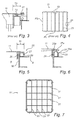
- Fig 3 illustrates a prior art cover sealing arrangement.
- a sealing strip 13 which is disposed between the cover 11 and cover overlapping areas 15 around the opening 9, abuts the cover 11.
- the sealing strip 13 is made of an elastic material and has, in the illustrated case, a cross section in the form of a half circle.
- the sealing strip 13 is compressed by the total load of the cover which includes the weight of the cover 11 in addition to the load resulting from the under-pressure in the sealed space.
- a locking device 17 is provided on top wall 8 to ensure the cover 11 is not lifted up by an over-pressure in interior 3a, which may nevertheless occur temporarily.
- Fig 4 shows a prior art cover 11 and illustrates one reason why the substantial residual gas leakage may occur.
- Cover 11 typically has approximately the proportions 3:4 and cannot be regarded as entirely stiff, unless the cover is very heavy and correspondingly expensive. Therefore, the pressure on the sealing strip 13 at midpoint, PL, of long cover edge 19 will be considerably higher than the pressure on the sealing strip 13 at midpoint, PS, along the shorter cover edge 21 of cover 11. This effect is increased if cover 11 has reinforcement ribs 23 that run parallel with the shorter cover edges 21, as illustrated in fig 4 . Due to the noted shortcomings of prior art covers and sealing arrangements, improved sealing arrangements/covers are needed.
- Fig 5 and 6 illustrate a cross section through a sealing arrangement 25 according to the present disclosure in a closed and in an opened position, respectively.
- This sealing arrangement 25 includes a compression limiting device 26 in the form of a flange, that extends upwardly from opening edge 9b away from top wall 8 to form free edge 26a.
- Flange 26 projects from opening edge 9b around opening 9. Free edge 26a of flange 26 abuts or interacts with cover 11 when in its closed position, covering opening 9.
- a distance, D that may be about 25 mm, away from flange 26 there is optionally a flange 29.
- Flange 29 is attached to top wall 8 and extends upwardly away from top wall 8 to form free edge 29a. Distance D may be adjusted depending on the sealing capacity requirements of sealing arrangement 25.
- a flexible sealing strip 27 having a height greater than that of flange 26 is provided.
- the uncompressed height of the sealing strip 27 may be about 40 mm and the height of the flange 26 may be about 30mm. Due to the height and flexibility of sealing strip 27, sealing strip 27 is compressed or deformed by cover 11 when in its closed position to provide a gastight sealing function. However, when the sealing strip 27 becomes compressed to a certain extent, in the example 10 mm, cover 11 contacts compression limiting device 26, thus preventing further compression of sealing strip 27. By preventing further compression of sealing strip 27, sealing strip 27 remains uniformly compressed along the entire periphery of opening 9. Only a portion of the load of cover 11 is supported by sealing strip 27, which may thus be specifically designed for sealing functionality rather than with load carrying abilities in mind.
- sealing strip 27 may be hollow, or as an alternative, filled such as for example with foam, and have a cross section suitable for a snug fit between flanges 26 and 29 with an arc-shaped exposed top portion 27a.
- sealing strip 27 may be a profile constructed with a "U" cross section, wherein the sides of the U snugly fit between flanges 26 and 29 and the curved base serving as exposed top portion 27a. This profile is considered hollow as it defines an inner volume that can e.g. be filled with foam.
- the second flange may be about 25 mm.
- Exposed top portion 27a of the sealing strip 27 is arc-shaped and constructed to ensure that continuous, substantially gastight contact exists between sealing strip 27 and cover 11 when cover 11 is fitted over opening 9, even if the cover 11 is not precisely parallel with the top wall 8 at the location of contact with the sealing strip 27.
- This may be advantageous as cover 11 may be slightly inclined at one or more portions of the cover periphery, as illustrated by the dashed line in fig 6 .
- the non-flexed shape of the cover 11 in fig 5 can thus be considered somewhat ideal. Still continuous, substantially gastight contact between sealing strip 27 and cover 11 can be maintained.
- sealing strip designs are possible in meeting the sealing and support requirements necessary.
- a number of various cross sectional shapes could be considered such as for example square, rectangular, circular, and the like.
- a solid sealing strip, a hollow sealing strip or a hollow, filled sealing strip could be used.
- a foam filled tube or like profile can be relatively soft and yet have a durable outer surface. At the same time, should this durable surface be punctured, the inner, soft foam still prevents leakage through sealing strip 27.
- a Fluoroelastomer such as Viton® DuPont Performance Elastomers L.L.C., Wilmington Delaware, USA is one material considered for the sealing strip, whether or not filled with foam.
- the compression limiting device 26 includes a flange extending perpendicularly from the cover-overlapping area 15 around the opening 9. Flange 26 extends upwardly away from the cover overlapping area 15 less than sealing strip 27. As soon as sealing strip 27 is compressed to a certain degree by cover 11, compression limiting device 26 supports the remaining cover 11 load. Thus, the sealing strip 27 supports only a portion, usually a small fraction, of the load from cover 11.
- the compression limiting device 26 is illustrated in fig. 5 and fig. 6 as flanges 26 and 29 surrounding opening 9.
- each of the flanges 26 and 29 could be a single flange or a plurality of flanges without impairing function.
- the form of the compression limiting device 26 may vary.
- the compression limiting device 26 may be in the form of a plurality of cylinders or blocks of matching height extending upwardly away from top wall 8 at regular intervals around opening 11 would provide a similar function.
- the compression limiting device 26 need not extend perpendicularly from top wall 8 but rather may extend therefrom at an angle or angles.
- both the sealing strip 27 and the compression limiting device 26 are attached to top wall 8 around opening 9.
- either, or both, could instead be attached to cover 11 at the corresponding opposed position.
- sealing arrangement 25 includes a second flange 29, parallel to first flange 26, such that a channel is formed therebetween, wherein the sealing strip 27 is placed.
- the second flange 29 need not function as a compression limiting device even if this is also an option.
- the second flange 29 may singularly serve to prevent sealing strip 27 from expanding outwardly away from first flange 26, such that sealing strip 27 supports less of the load from cover 11.
- the sealing strip may, in its compressed state, substantially fill the channel formed between the first and second flanges 26, 29.
- a locking device e.g. similar to the one illustrated in fig 3 could be provided.
- Fig 7 illustrates an improved cover.
- the cover 11' has reinforcement ribs 31 and 33 positioned or formed in directions parallel with the long and short edges of cover 11'.
- a cover 11' which need not be rectangular, may have stiffness improving means positioned or formed in more than one direction, such that the flexural rigidity of cover 11' is substantially the same, regardless of the axis across which cover 11' is flexed. This may be achieved by varying spacing or dimensions of the reinforcement ribs, or the like.
- cover 11' Thanks to the uniform flexural rigidity of cover 11', cover 11' distributes a more uniform pressure on sealing arrangement 27, thereby reducing the performance characteristics required from sealing arrangement 27.
Landscapes
- Engineering & Computer Science (AREA)
- General Engineering & Computer Science (AREA)
- Mechanical Engineering (AREA)
- Chemical & Material Sciences (AREA)
- Chemical Kinetics & Catalysis (AREA)
- Physics & Mathematics (AREA)
- Geometry (AREA)
- Gasket Seals (AREA)
Abstract
Description
- The present invention relates to a sealing arrangement for a cover suitable for covering an opening. More particularly, the sealing arrangement comprises at least one deformable sealing strip disposed between said cover and cover overlapping areas, which surround said opening and which abut the cover via the sealing strip when the opening is covered.
- Such sealing arrangements are used e.g. to cover maintenance openings, providing access to textile filter plenary spaces. Often, it is important that the sealing arrangement is very tight. This is due to the fact that textile filters often operate at pressures lower than atmospheric pressure, and that air, leaking into the filter, may lower the operational temperature and cause undesirable effects, such as condensation.
- An object of the present disclosure is to provide a sealing arrangement, suitable for use in sealing a fabric filter cover, with improved sealing capability. This object is achieved by means of the sealing arrangement described herein and defined in the claims below.
- Sealing arrangements of the present invention comprise a compression limiting device attached to areas surrounding an opening that overlap a cover when the cover is positioned over the opening. The compression limiting device limits the compression of a deformable sealing strip attached between the cover overlapping areas and the cover such that the sealing strip is compressed to a degree but carries only a portion of the cover weight/load when the opening is covered by the cover. Accordingly, the sealing strip is substantially uniformly compressed along its entire length providing for improved sealing capabilities with regard to providing a relatively long-lasting gastight seal.
- The sealing strip may be devised as a hollow tube or like a profile that may be filled with a foam material.
- The compression limiting device may include a flange extending from the cover overlapping area and defining a first edge, having a flange height that is smaller than the height of the sealing strip in its uncompressed state.
- Additionally, a second flange may be provided extending from the cover overlapping area and defining a second edge, having a flange height that is smaller than the flange height of the first flange, wherein a channel is formed between the first and second flanges, and wherein the sealing strip, in its compressed state, substantially fills the distance/channel between first and second flanges.
- The compression limiting device may further be optimised for sealing rather than load carrying purposes.
- The opening may provide an entry into a plenary space of a textile filter unit, which plenary space has a pressure below atmospheric pressure when the textile filter unit is operating.
- The cover may further be provided with stiffness improving means running in more than one direction over, under and/or through the cover, such that the flexural rigidity of the cover is substantially the same, regardless of the axis across which the cover is flexed.
- The sealing strip may be attached to the cover overlapping areas and may comprise an arc-shaped top portion for contact with the cover.
-
-
Fig 1 and 2 illustrate, schematically, a textile or fabric filter unit. -
Fig 3 shows a prior art cover sealing arrangement. -
Fig 4 illustrates a prior art cover. -
Fig 5 and 6 illustrate a cross section through a sealing arrangement in accordance with the present disclosure in an opened and in a closed position, respectively. -
Fig 7 illustrates an improved cover. -
Fig 1 and 2 illustrate, schematically, a fabric filter unit 1 where the cover sealing arrangement of the present disclosure is useful. The fabric filter unit may be used to remove particles from a flue gas, which may be generated from a combustion process such as for example burning coal, oil, waste, and/or the like. The shown fabric filter unit 1 includes sixfilter sections 3, one of which is illustrated in greater detail infig 2 . Eachfilter section 3 has a plurality of hose-shaped textile/fabric filter elements 5 which present a considerable filter area to aflue gas 7 that is passed through fabric filter unit 1. - In order to allow maintenance of
filter section 3 and replacement offilter elements 5, anopening 9 is provided in atop wall 8 offilter section 3. During operation of fabric filter unit 1, opening 9 is completely covered by acover 11. A sealing arrangement in accordance with the present disclosure as disclosed in more detail below provides a substantially gastight seal between thecover 11 andtop wall 8. - Usually, the
interior 3a offilter section 3 is below atmospheric pressure. Leakage of cold ambient air intofilter section 3 is undesirable as such lowers the flue gas temperature and makes the flue gases condensate to a greater extent. Upon condensation, chemically aggressive components of the flue gases may cause excessive corrosion infilter section 3. This excessive corrosion problem is particularly severe in waste incineration processes, which may be difficult control and may include a significant amount of hydrochloric acid. Hence, there exists a need for reliable gastight sealing arrangements fortop cover 11. It should be noted that thetop cover 11 in many cases may be relatively large, typically 3x4 metres. -
Fig 3 illustrates a prior art cover sealing arrangement. In this arrangement asealing strip 13, which is disposed between thecover 11 and cover overlappingareas 15 around the opening 9, abuts thecover 11. - The
sealing strip 13 is made of an elastic material and has, in the illustrated case, a cross section in the form of a half circle. Thesealing strip 13 is compressed by the total load of the cover which includes the weight of thecover 11 in addition to the load resulting from the under-pressure in the sealed space. Even though a filter unit of the kind illustrated infig 1 and 2 is usually operated under ambient pressure, alocking device 17 is provided ontop wall 8 to ensure thecover 11 is not lifted up by an over-pressure ininterior 3a, which may nevertheless occur temporarily. - In the prior art configuration, it has been found that a substantial residual gas leakage may still occur even though the
sealing strip 13 is provided.Fig 4 shows aprior art cover 11 and illustrates one reason why the substantial residual gas leakage may occur.Cover 11 typically has approximately the proportions 3:4 and cannot be regarded as entirely stiff, unless the cover is very heavy and correspondingly expensive. Therefore, the pressure on thesealing strip 13 at midpoint, PL, oflong cover edge 19 will be considerably higher than the pressure on thesealing strip 13 at midpoint, PS, along theshorter cover edge 21 ofcover 11. This effect is increased ifcover 11 hasreinforcement ribs 23 that run parallel with theshorter cover edges 21, as illustrated infig 4 . Due to the noted shortcomings of prior art covers and sealing arrangements, improved sealing arrangements/covers are needed. -
Fig 5 and 6 illustrate a cross section through asealing arrangement 25 according to the present disclosure in a closed and in an opened position, respectively. Thissealing arrangement 25 includes acompression limiting device 26 in the form of a flange, that extends upwardly fromopening edge 9b away fromtop wall 8 to formfree edge 26a. Flange 26 projects fromopening edge 9b around opening 9.Free edge 26a offlange 26 abuts or interacts withcover 11 when in its closed position, covering opening 9. A distance, D, that may be about 25 mm, away fromflange 26 there is optionally aflange 29.Flange 29 is attached totop wall 8 and extends upwardly away fromtop wall 8 to formfree edge 29a. Distance D may be adjusted depending on the sealing capacity requirements ofsealing arrangement 25. Aflexible sealing strip 27 having a height greater than that offlange 26 is provided. Typically, the uncompressed height of thesealing strip 27 may be about 40 mm and the height of theflange 26 may be about 30mm. Due to the height and flexibility ofsealing strip 27,sealing strip 27 is compressed or deformed bycover 11 when in its closed position to provide a gastight sealing function. However, when thesealing strip 27 becomes compressed to a certain extent, in the example 10 mm, cover 11 contactscompression limiting device 26, thus preventing further compression ofsealing strip 27. By preventing further compression of sealingstrip 27,sealing strip 27 remains uniformly compressed along the entire periphery of opening 9. Only a portion of the load ofcover 11 is supported bysealing strip 27, which may thus be specifically designed for sealing functionality rather than with load carrying abilities in mind. - As illustrated in
fig 6 ,sealing strip 27 may be hollow, or as an alternative, filled such as for example with foam, and have a cross section suitable for a snug fit betweenflanges top portion 27a. As an alternative, sealingstrip 27 may be a profile constructed with a "U" cross section, wherein the sides of the U snugly fit betweenflanges top portion 27a. This profile is considered hollow as it defines an inner volume that can e.g. be filled with foam. The second flange may be about 25 mm. - Exposed
top portion 27a of the sealingstrip 27 is arc-shaped and constructed to ensure that continuous, substantially gastight contact exists between sealingstrip 27 and cover 11 whencover 11 is fitted overopening 9, even if thecover 11 is not precisely parallel with thetop wall 8 at the location of contact with the sealingstrip 27. This may be advantageous ascover 11 may be slightly inclined at one or more portions of the cover periphery, as illustrated by the dashed line infig 6 . The non-flexed shape of thecover 11 infig 5 can thus be considered somewhat ideal. Still continuous, substantially gastight contact between sealingstrip 27 and cover 11 can be maintained. - Many sealing strip designs are possible in meeting the sealing and support requirements necessary. First of all, a number of various cross sectional shapes could be considered such as for example square, rectangular, circular, and the like. Secondly, a solid sealing strip, a hollow sealing strip or a hollow, filled sealing strip could be used.
- Yet another suitable option is a foam filled tube or like profile. Such a tube or profile can be relatively soft and yet have a durable outer surface. At the same time, should this durable surface be punctured, the inner, soft foam still prevents leakage through sealing
strip 27. - A Fluoroelastomer such as Viton® (DuPont Performance Elastomers L.L.C., Wilmington Delaware, USA) is one material considered for the sealing strip, whether or not filled with foam.
- In the case illustrated in
fig. 5 and fig. 6 , thecompression limiting device 26 includes a flange extending perpendicularly from the cover-overlappingarea 15 around theopening 9.Flange 26 extends upwardly away from thecover overlapping area 15 less than sealingstrip 27. As soon as sealingstrip 27 is compressed to a certain degree bycover 11,compression limiting device 26 supports the remainingcover 11 load. Thus, the sealingstrip 27 supports only a portion, usually a small fraction, of the load fromcover 11. - The
compression limiting device 26 is illustrated infig. 5 and fig. 6 asflanges surrounding opening 9. However, other embodiments are also possible. For example, each of theflanges compression limiting device 26 may vary. For example, rather than one or more flanges, thecompression limiting device 26 may be in the form of a plurality of cylinders or blocks of matching height extending upwardly away fromtop wall 8 at regular intervals around opening 11 would provide a similar function. Thecompression limiting device 26 need not extend perpendicularly fromtop wall 8 but rather may extend therefrom at an angle or angles. - In the case illustrated in
fig. 5 and fig. 6 , both the sealingstrip 27 and thecompression limiting device 26 are attached totop wall 8 aroundopening 9. However either, or both, could instead be attached to cover 11 at the corresponding opposed position. - In illustrated in
fig. 5 and fig. 6 , sealingarrangement 25 includes asecond flange 29, parallel tofirst flange 26, such that a channel is formed therebetween, wherein the sealingstrip 27 is placed. Thesecond flange 29 need not function as a compression limiting device even if this is also an option. Thesecond flange 29 may singularly serve to prevent sealingstrip 27 from expanding outwardly away fromfirst flange 26, such that sealingstrip 27 supports less of the load fromcover 11. The sealing strip may, in its compressed state, substantially fill the channel formed between the first andsecond flanges - A locking device, e.g. similar to the one illustrated in
fig 3 could be provided. -
Fig 7 illustrates an improved cover. As illustrated, the cover 11' hasreinforcement ribs - Thanks to the uniform flexural rigidity of cover 11', cover 11' distributes a more uniform pressure on sealing
arrangement 27, thereby reducing the performance characteristics required from sealingarrangement 27. - The invention is not limited to the disclosed embodiments and may be altered in different ways within the scope of the appended claims. The specified measures mentioned above are of course examples that can be varied in accordance with a specific application.
Claims (8)
- A sealing arrangement for a cover (11), covering an opening (9), the sealing arrangement comprising at least one deformable sealing strip (27) disposed between said cover and a cover overlapping area (15), which surrounds said opening, characterized by a compression limiting device (26) attached to the cover overlapping areas or the cover, which limits the compression of the deformable sealing strip such that the sealing strip is compressed but carries only a portion of the cover load when the opening is covered by the cover.
- A sealing arrangement according to claim 1, wherein the deformable sealing strip is a hollow tube or profile.
- A sealing arrangement according to claim 2, wherein the hollow tube or profile is filled with a foam material.
- A sealing arrangement according to any of the preceding claims, wherein the sealing strip is attached to the cover overlapping areas and the compression limiting device includes a first flange (26), extending from the cover overlapping area, and having a height that is smaller than the height of the sealing strip in the latter's uncompressed state.
- A sealing arrangement according to claim 4, wherein the sealing arrangement includes a second flange (29), extending from the cover overlapping area, and having a height that is smaller than the height of the first flange, wherein a channel is formed between the first and second flanges, and wherein the sealing strip, in its compressed state, substantially fills the channel.
- A sealing arrangement according to any of the preceding claims, wherein the opening (9) is an entry into a plenary space of a textile filter unit (1), which plenary space has a pressure below atmospheric pressure when the textile filter unit is operating.
- A sealing arrangement according to any of the preceding claims wherein the cover (11') has stiffness increasing means (31, 33) extending in more than one direction, such that the flexural rigidity of the cover is substantially the same, regardless of the axis across which the cover is flexed.
- A sealing arrangement according to any of the preceding claims, wherein the sealing strip is attached to the cover overlapping areas and comprises a rounded uppermost portion.
Priority Applications (1)
| Application Number | Priority Date | Filing Date | Title |
|---|---|---|---|
| EP20100151192 EP2348235A1 (en) | 2010-01-20 | 2010-01-20 | Sealing arrangement |
Applications Claiming Priority (1)
| Application Number | Priority Date | Filing Date | Title |
|---|---|---|---|
| EP20100151192 EP2348235A1 (en) | 2010-01-20 | 2010-01-20 | Sealing arrangement |
Publications (1)
| Publication Number | Publication Date |
|---|---|
| EP2348235A1 true EP2348235A1 (en) | 2011-07-27 |
Family
ID=42238819
Family Applications (1)
| Application Number | Title | Priority Date | Filing Date |
|---|---|---|---|
| EP20100151192 Withdrawn EP2348235A1 (en) | 2010-01-20 | 2010-01-20 | Sealing arrangement |
Country Status (1)
| Country | Link |
|---|---|
| EP (1) | EP2348235A1 (en) |
Citations (7)
| Publication number | Priority date | Publication date | Assignee | Title |
|---|---|---|---|---|
| GB814265A (en) * | 1956-04-05 | 1959-06-03 | Mann & Hummel Filter | Improvements in or relating to sealing rings |
| DE3141054A1 (en) * | 1981-10-15 | 1983-04-28 | CEAG Verfahrenstechnik GmbH, 4714 Selm | Filtering precipitator |
| JPS63302015A (en) * | 1987-05-30 | 1988-12-08 | Tadao Shirai | Manufacture of continuous elastic sealing material |
| EP0726389A1 (en) * | 1995-02-08 | 1996-08-14 | FILTERWERK MANN & HUMMEL GMBH | Air filter housing for internal combustion engine |
| DE102004056842B3 (en) * | 2004-11-25 | 2006-02-09 | Daimlerchrysler Ag | Ventilation device for vehicle has hollow of seal with locking pin projecting from resting region through assembly recesses |
| US20070261662A1 (en) * | 2004-10-08 | 2007-11-15 | Mann & Hummel Gmbh | Compact filter comprising a square seal |
| US20090261532A1 (en) * | 2008-04-17 | 2009-10-22 | Morehead Mason D | Compression-limited gasket construction |
-
2010
- 2010-01-20 EP EP20100151192 patent/EP2348235A1/en not_active Withdrawn
Patent Citations (7)
| Publication number | Priority date | Publication date | Assignee | Title |
|---|---|---|---|---|
| GB814265A (en) * | 1956-04-05 | 1959-06-03 | Mann & Hummel Filter | Improvements in or relating to sealing rings |
| DE3141054A1 (en) * | 1981-10-15 | 1983-04-28 | CEAG Verfahrenstechnik GmbH, 4714 Selm | Filtering precipitator |
| JPS63302015A (en) * | 1987-05-30 | 1988-12-08 | Tadao Shirai | Manufacture of continuous elastic sealing material |
| EP0726389A1 (en) * | 1995-02-08 | 1996-08-14 | FILTERWERK MANN & HUMMEL GMBH | Air filter housing for internal combustion engine |
| US20070261662A1 (en) * | 2004-10-08 | 2007-11-15 | Mann & Hummel Gmbh | Compact filter comprising a square seal |
| DE102004056842B3 (en) * | 2004-11-25 | 2006-02-09 | Daimlerchrysler Ag | Ventilation device for vehicle has hollow of seal with locking pin projecting from resting region through assembly recesses |
| US20090261532A1 (en) * | 2008-04-17 | 2009-10-22 | Morehead Mason D | Compression-limited gasket construction |
Similar Documents
| Publication | Publication Date | Title |
|---|---|---|
| EP2650572B1 (en) | Gasket | |
| US20050280214A1 (en) | Elastomer coated screen gasket | |
| US7063327B2 (en) | Sealing element | |
| US10156319B2 (en) | Gasholder sealing member and gasholder sealing structure | |
| KR101306828B1 (en) | Lip type seal | |
| US20110175299A1 (en) | Deformable composite seal for bearing surfaces with a great lack of flatness | |
| CN105650280A (en) | Rotary kiln sealing device and processing system with same | |
| ES2415630T3 (en) | Board intended for a sanitary ventilation structure due to overpressures | |
| JP2004204941A (en) | Gasket | |
| US20140027660A1 (en) | Low leakage flue damper | |
| US20130167492A1 (en) | Sealing device and method | |
| US20020113379A1 (en) | Sealing device | |
| RU2306248C2 (en) | Breather valve | |
| RU2223437C2 (en) | Breathing valve | |
| JPH11255290A (en) | Floating roof of floating roof storage tank | |
| US8727161B2 (en) | Rim space seal system for use with internal floating roof | |
| KR101933176B1 (en) | Pressure-resistant bellows | |
| RU2641185C2 (en) | Segmented seal valve assembly | |
| US4387628A (en) | Chimney seal | |
| CN216045553U (en) | Pneumatic actuator prevents that high temperature valve leaks cover | |
| KR102056023B1 (en) | Sealed Type manhole cover | |
| KR102120918B1 (en) | Automation Bleeder Vent valve installed at external floating roof tank | |
| KR20150004181U (en) | Raised spiral wound gasket | |
| JP2006029587A (en) | Packing | |
| CN210423825U (en) | Water seal furnace top valve |
Legal Events
| Date | Code | Title | Description |
|---|---|---|---|
| PUAI | Public reference made under article 153(3) epc to a published international application that has entered the european phase |
Free format text: ORIGINAL CODE: 0009012 |
|
| AK | Designated contracting states |
Kind code of ref document: A1 Designated state(s): AT BE BG CH CY CZ DE DK EE ES FI FR GB GR HR HU IE IS IT LI LT LU LV MC MK MT NL NO PL PT RO SE SI SK SM TR |
|
| AX | Request for extension of the european patent |
Extension state: AL BA RS |
|
| 17P | Request for examination filed |
Effective date: 20120125 |
|
| 17Q | First examination report despatched |
Effective date: 20130411 |
|
| GRAP | Despatch of communication of intention to grant a patent |
Free format text: ORIGINAL CODE: EPIDOSNIGR1 |
|
| INTG | Intention to grant announced |
Effective date: 20160603 |
|
| RAP1 | Party data changed (applicant data changed or rights of an application transferred) |
Owner name: GENERAL ELECTRIC TECHNOLOGY GMBH |
|
| STAA | Information on the status of an ep patent application or granted ep patent |
Free format text: STATUS: THE APPLICATION IS DEEMED TO BE WITHDRAWN |
|
| 18D | Application deemed to be withdrawn |
Effective date: 20161014 |