EP2348232A1 - Vehicle hydraulic control unit - Google Patents
Vehicle hydraulic control unit Download PDFInfo
- Publication number
- EP2348232A1 EP2348232A1 EP10009882A EP10009882A EP2348232A1 EP 2348232 A1 EP2348232 A1 EP 2348232A1 EP 10009882 A EP10009882 A EP 10009882A EP 10009882 A EP10009882 A EP 10009882A EP 2348232 A1 EP2348232 A1 EP 2348232A1
- Authority
- EP
- European Patent Office
- Prior art keywords
- vane
- pump
- discharge
- control unit
- engine
- Prior art date
- Legal status (The legal status is an assumption and is not a legal conclusion. Google has not performed a legal analysis and makes no representation as to the accuracy of the status listed.)
- Withdrawn
Links
Images




Classifications
-
- F—MECHANICAL ENGINEERING; LIGHTING; HEATING; WEAPONS; BLASTING
- F16—ENGINEERING ELEMENTS AND UNITS; GENERAL MEASURES FOR PRODUCING AND MAINTAINING EFFECTIVE FUNCTIONING OF MACHINES OR INSTALLATIONS; THERMAL INSULATION IN GENERAL
- F16H—GEARING
- F16H57/00—General details of gearing
- F16H57/04—Features relating to lubrication or cooling or heating
- F16H57/0434—Features relating to lubrication or cooling or heating relating to lubrication supply, e.g. pumps; Pressure control
-
- F—MECHANICAL ENGINEERING; LIGHTING; HEATING; WEAPONS; BLASTING
- F16—ENGINEERING ELEMENTS AND UNITS; GENERAL MEASURES FOR PRODUCING AND MAINTAINING EFFECTIVE FUNCTIONING OF MACHINES OR INSTALLATIONS; THERMAL INSULATION IN GENERAL
- F16H—GEARING
- F16H61/00—Control functions within control units of change-speed- or reversing-gearings for conveying rotary motion ; Control of exclusively fluid gearing, friction gearing, gearings with endless flexible members or other particular types of gearing
- F16H61/0021—Generation or control of line pressure
- F16H61/0025—Supply of control fluid; Pumps therefor
- F16H61/0031—Supply of control fluid; Pumps therefor using auxiliary pumps, e.g. pump driven by a different power source than the engine
-
- F—MECHANICAL ENGINEERING; LIGHTING; HEATING; WEAPONS; BLASTING
- F16—ENGINEERING ELEMENTS AND UNITS; GENERAL MEASURES FOR PRODUCING AND MAINTAINING EFFECTIVE FUNCTIONING OF MACHINES OR INSTALLATIONS; THERMAL INSULATION IN GENERAL
- F16H—GEARING
- F16H61/00—Control functions within control units of change-speed- or reversing-gearings for conveying rotary motion ; Control of exclusively fluid gearing, friction gearing, gearings with endless flexible members or other particular types of gearing
- F16H61/0021—Generation or control of line pressure
- F16H61/0025—Supply of control fluid; Pumps therefor
- F16H2061/0034—Accumulators for fluid pressure supply; Control thereof
Definitions
- the present invention relates to a vehicle hydraulic control unit using a vane pump that is driven by an engine.
- Patent Document 1 discloses a hydraulic control unit for a vehicle using a vane pump that is driven by an engine.
- the conventional vehicle hydraulic control unit supplies discharge oil pressure from a vane, which is driven by an engine, to a continuously variable transmission (CVT) that shifts output rotation of the engine.
- CVT continuously variable transmission
- the vane pump accommodates vanes, which can protrude to or retract from a great number of vane grooves formed radially on a rotor that is mounted to a pump shaft, wherein a cam ring surrounds the rotor and the vanes to define a pump chamber.
- a side plate provided along the cam ring is provided so as to communicate a discharge port corresponding to a discharge-side pump chamber and a vane back pressure supplying port corresponding to a vane back pressure chamber at the center of the vane groove with each other.
- the leading end of the vane is pressed against the inner peripheral guide surface of the cam ring by centrifugal force caused by the rotation of the rotor and the back pressure supplied to the vane back pressure chamber, whereby the pump chamber is defined and formed.
- hydraulic fluid supplied to the vane back pressure chamber might be leaked out from the discharge port, or the hydraulic fluid sucked into the pump chamber might be leaked out from a suction port or the discharge port. Since the hydraulic fluid in the vane back pressure chamber or in the pump chamber is eliminated, self-priming performance of the hydraulic fluid to the pump chamber and discharge response of the hydraulic fluid from the pump chamber might be deteriorated upon the re-start of the vane pump, i.e., when the engine is started again.
- An object of the present invention is to provide a vehicle hydraulic control unit capable of preventing a vane from being pulled into a vane groove, when a vane pump driven by an engine stops.
- the present invention relate to a vehicle hydraulic control unit comprising a vane pump driven by an engine.
- the vane pump accommodates vanes in many vane grooves, which are radially formed on a rotor provided to a pump shaft, so as to be capable of protruding to or retracting from the vane grooves.
- a cam ring surrounds the rotor and the vanes to define a pump chamber, and discharge oil from the pump chamber is supplied to a center-side vane back pressure chamber in the vane groove.
- the discharge oil from an external oil pressure supplying apparatus can be supplied to the vane back pressure chamber of the vane pump during the stopped state of the engine.
- the present invention relate to a vehicle hydraulic control unit comprising a vane pump driven by an engine.
- the vane pump accommodates vanes in many vane grooves, which are radially formed on a rotor provided to a pump shaft, so as to be capable of protruding to or retracting from the vane grooves.
- a cam ring surrounds the rotor and the vanes to define a pump chamber.
- a side plate provided along the cam ring communicates a discharge port corresponding to a discharge-side pump chamber and a vane back pressure supplying port corresponding to a center-side vane back pressure chamber in the vane groove.
- the discharge oil from an external oil pressure supplying apparatus can be supplied to the discharge port of the vane pump during the stopped state of the engine.
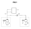
- FIG. 1 illustrates a first embodiment of a vehicle hydraulic control unit according to the present invention.
- the vehicle hydraulic control unit includes a vane pump 10 that is driven by an engine 1, and controls, for example, a hydraulic control type continuously variable transmission (hereinafter referred to as CVT) 2 by a hydraulic fluid discharged from the vane pump 10.
- a suction pipe line 3 is connected to a suction opening (later-described suction opening 24) of the vane pump 10
- a discharge pipe line 4 is connected to a discharge opening (later-described discharge opening 28) of the vane pump 10.
- the vane pump 10 can be a variable capacity vane pump illustrated in FIGS. 4 and 5 .
- the vane pump 10 has a rotor 13 that is fixed to a pump shaft 12, which is inserted into a pump casing 11, by a serration, and that is driven to rotate.
- the pump shaft 12 is directly driven to rotate by the engine 1.
- the rotor 13 accommodates vanes 15, which can protrude into or retract from a great number of vane grooves 14 that are radially formed at many respective positions in the circumferential direction of the rotor 13, wherein the rotor 13 can move each vane 15 in the radius direction along the vane grooves 14.
- a side plate 17 and an adapter ring 18 are fitted in a fitting hole 16 of a pump housing 11A of the pump casing 11 in a laminated state. They are positioned in the circumferential direction by a support pin 19, and fixed and held by a cover 11 B from the side.
- a cam ring 20 is fitted to the above-mentioned adapter ring 18 fixed to the pump housing 11A of the pump casing 11.
- the cam ring 20 is supported by the support pin 19, which is provided at the lowermost part of the adapter ring 18 in the vertical direction, in such a manner that the cam ring 20 can be pivoted and displaced.
- the cam ring 20 encloses the rotor 13 and the vanes 15 with a certain eccentric amount with the rotor 13, thereby forming a pump chamber 21 between the outer periphery of the rotor 13 and the adjacent vanes 15 between the side plate 17 and the cover 11 B.
- a suction port 22 formed on the cover 11 B is open to the suction region at the upstream side of the pump chamber 21 in the rotating direction of the rotor.
- the suction port 22 is allowed to communicate with the suction opening 24 of the pump 10 through a suction passage (drain passage) 23 formed to the housing 11A and the cover 11 B.
- the discharge port 25 formed on the side plate 17 is open to the discharge region at the downstream side of the pump chamber 21 in the rotor-rotating direction.
- the discharge port 25 is allowed to communicate with the discharge opening 28 of the pump 10 through a high-pressure chamber 26 and a discharge passage 27 provided to the housing 11A.
- the side plate 17 provided along one side of the cam ring 20 is provided with a vane back pressure supplying port 29 that guides a high-pressure discharge oil in the high-pressure chamber 26 to a vane back pressure chamber 14A of the vane groove 14 at the center of the rotor 13.
- the side plate 17 is provided so as to communicate the discharge port 25 corresponding to the pump chamber 21 at the discharge side and the vane back pressure supplying port 29 corresponding to the center-side vane back pressure chamber 14A in the vane groove 14 with each other by the high-pressure chamber 26.
- the rotor 13 is rotated by the engine 1, whereby each vane 15 rotates with the leading end thereof being pressed against the inner peripheral cam surface of the cam ring 20 due to the centrifugal force caused by the rotation of the rotor 13 and the back pressure supplied to the vane back pressure chamber 14A from the vane back pressure supplying port 29.
- the volume formed between the adjacent vanes 15 and the cam ring 20 is increased with the rotation, whereby the hydraulic fluid is sucked from the suction port 22.
- the volume formed between the adjacent vanes 15 and the cam ring 20 is decreased with the rotation, whereby the hydraulic fluid is discharged from the discharge port 25.
- the vane pump 10 has first and second fluid pressure chambers 31 and 32 between the adapter ring 18 and the cam ring 20, and has a pressure cylinder 33 and a spring 34 at the side opposite to the first fluid pressure chamber 31 across the cam ring 20. Fluid pressures guided from the discharge passage of the pump 10 through a switching valve device 35 are supplied to the first fluid pressure chamber 31, the second fluid pressure chamber 32, and an oil chamber of the pressure cylinder 33. The cam ring 20 is moved against the biasing force of the spring 34 with the balance of these pressures to change the volume in the pump 21, whereby the discharge rate of the pump 10 is controlled.
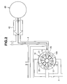
- an external pump 40 serving as an external oil pressure supplying apparatus is connected to the discharge pipe line 4 that is connected to the discharge opening 28 of the vane pump 10 in the vehicle hydraulic control unit illustrated in FIG. 1 .
- the external pump 40 is driven by an electric motor 41, whereby the discharge oil pressure in the external pump 40 is supplied to the discharge pipe line 4 of the vane pump 10 through a one-way valve 42 (in the present embodiment, a check valve).
- the one-way and check valves of the present invention are standard operation check valves in that they are not arranged to provide any damping in the open position, and are not designed to throttle fluid flow during the transition from open to closed, or closed to open.
- the rotation of the vane pump 10 driven by the engine 1 also stops to discontinue the discharge of the hydraulic fluid.
- an unillustrated controller drives the electric motor 41 to drive the external pump 40.
- the discharge oil pressure of the external pump 40 is supplied to the discharge pipe line 4 of the vane pump 10, the high-pressure chamber 26 of the vane pump 10, and the discharge port 25 through the one-way valve 42, and further, supplied to the vane back pressure supplying port 29 and the vane back pressure chamber 14A.
- FIG. 3A illustrates the example of the present invention in which the oil pressure in the external pump 40 is supplied to the vane back pressure chamber 14A of the vane pump 10, and the leading end of the vane 15 projecting from the vane groove 14 is pressed in against the inner peripheral cam surface of the cam ring 20.
- FIG. 3B illustrates the case of the conventional example in which the hydraulic fluid is not supplied to the vane back pressure chamber 14A of the vane pump 10, so that the vane 15 is pulled into the vane groove 14 by its own weight.
- the structure according to the present invention can prevent the hydraulic fluid supplied to the vane back pressure chamber 14A from leaking out from the discharge port 25 and can prevent the hydraulic fluid sucked into the pump chamber 21 from leaking out from the suction port 22 or the discharge port 25. Since there is no chance that there is no hydraulic fluid in the vane back pressure chamber 14A and the pump chamber 21 during the stop of the vane pump 10, the self-priming performance of the hydraulic fluid to the pump chamber 21 and the discharge response of the hydraulic fluid from the pump chamber 21 can be enhanced, when the vane pump 10 is restarted, i.e., when the engine 1 is again started.
- the external pump used in the present invention may be used as an oil pressure source that supplies oil pressure to the CVT 2 or the like of the vehicle during the stop of the vane pump 10 caused by the stop of the engine 1.
- FIG. 6 illustrates a second embodiment of a vehicle hydraulic control unit according to the present invention.
- the different point of the second embodiment from the first embodiment in FIG. 1 is such that an accumulator 50 is used as an external oil pressure supplying apparatus.
- the accumulator 50 is connected so as to always communicate with the discharge pipe line 4 connected to the discharge opening 28 of the vane pump 10. Pressure is accumulated in the accumulator 50 by the discharge oil of the vane pump 10 driven by the engine 1.
- the rotation of the vane pump 10 driven by the engine 1 also stops, whereby discharge of the hydraulic fluid is discontinued.
- the hydraulic fluid accumulated in the accumulator 50 is naturally supplied to the discharge pipe line 4 of the vane pump 10 as well as the high-pressure chamber 26 and the discharge port 25 of the vane pump 10, and further, is supplied to the vane back pressure supplying port 29 and the vane back pressure chamber 14A.
- the structure according to the present invention can prevent the hydraulic fluid supplied to the vane back pressure chamber 14A from leaking out from the discharge port 25 and can prevent the hydraulic fluid sucked into the pump chamber 21 from leaking out from the suction port 22 or the discharge port 25. Since there is no chance that there is no hydraulic fluid in the vane back pressure chamber 14A and the pump chamber 21 during the stoppage of the vane pump 10, the self-priming performance of the hydraulic fluid to the pump chamber 21 and the discharge response of the hydraulic fluid from the pump chamber 21 can be enhanced, when the vane pump 10 is restarted, i.e., when the engine 1 is again started.
- the vane pump to which the present invention is applied can be a fixed capacity type vane pump 110.
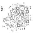
- a vane pump 110 includes, as illustrated in FIGS. 7 to 9 , for example, a rotor 113 that is fixed to a pump shaft 112, which is inserted into a pump casing 111, by a serration to be rotated.
- the pump shaft 112 is directly driven to rotate by the engine 1.
- the rotor 113 accommodates vanes 115, which can protrude into or retract from a great number of vane grooves 114 that are radially formed at many respective positions in the circumferential direction of the rotor 113, wherein the rotor 113 can move each vane 115 in the radial direction along the vane grooves 114.
- a side plate 117, a cam ring 118, and a side plate outer 119 are fitted in a fitting hole 116 of a pump housing 111A of the pump casing 111 in a laminated state. They are positioned in the circumferential direction by positioning pins 120 and 121, and fixed and held by a housing plate 111 B from the side.
- the cam ring 118 encloses the rotor 113 and the vanes 115, thereby forming a pump chamber 122 between the outer periphery of the rotor 113 and the adjacent vanes 115 between the side plate 117 and the side plate outer 119.
- a suction port 123 formed on the cam ring 118 is open to the suction region at the upstream side of the pump chamber 122 in the rotating direction of the rotor.
- the suction port 123 is allowed to communicate with the suction opening 125 of the pump 110 through a suction passage 124 formed in the housing 111A.
- the discharge port 126 formed on the side plate outer 119 is open to the discharge region at the downstream side of the pump chamber 122 in the rotor-rotating direction.
- the discharge port 126 is allowed to communicate with the discharge opening 128 of the pump 110 through a discharge passage 127 provided in the housing plate 111 B.
- the side plate 117 provided along one side of the cam ring 118 is provided with a vane back pressure supply port 130 that guides high-pressure discharge oil in the high-pressure chamber 129 to a vane back pressure chamber 114A in the vane groove 114 at the center of the rotor 113.
- the side plate 117 is provided so as to communicate the discharge port 126 corresponding to the pump chamber 122 at the discharge side and the vane back pressure supplying port 130 corresponding to the center-side vane back pressure chamber 114A in the vane groove 114 with each other by the high-pressure chamber 129.
- the rotor 113 is rotated by the engine 1.
- Each vane 115 rotates with the leading end thereof being pressed against the inner peripheral cam surface of the cam ring 118 due to the centrifugal force caused by the rotation of the rotor 113 and the back pressure supplied to the vane back pressure chamber 114A from the vane back pressure supplying port 130.
- the volume formed between the adjacent vanes 115 and the cam ring 118 is increased with the rotation, whereby hydraulic fluid is sucked from the suction port 123.
- the volume formed between the adjacent vanes 115 and the cam ring 118 is decreased with the rotation, whereby the hydraulic fluid is discharged from the discharge port 126.
- the pump shaft 112, the rotor 113, the vane groove 114, the vane back pressure chamber 114A, the vane 115, the cam ring 118, the pump chamber 122, the suction port 123, the discharge port 126, the discharge opening 128, and the vane back pressure supplying port 130 in the vane pump 110 respectively correspond to the pump shaft 12, the rotor 13, the vane groove14, the vane back pressure chamber 14A, the vane 15, the cam ring 20, the pump chamber 21, the suction port 22, the discharge port 25, the discharge opening 28, and the vane back pressure supplying port 29 in the vane pump 10 described above.
- the present invention can supply discharge oil in an external oil pressure supplying apparatus to a vane back pressure chamber of a vane pump during stoppage of an engine, in a vehicle hydraulic control unit.
- This structure can prevent the vane from being pulled into a vane groove during stoppage of the vane pump that is driven by the engine, in the vehicle hydraulic control unit.
Landscapes
- Engineering & Computer Science (AREA)
- General Engineering & Computer Science (AREA)
- Mechanical Engineering (AREA)
- Rotary Pumps (AREA)
- Details And Applications Of Rotary Liquid Pumps (AREA)
- Control Of Transmission Device (AREA)
Abstract
A vehicle hydraulic control unit capable of preventing a vane from being pulled into a vane groove when a vane pump driven by an engine stops. The present hydraulic control unit supplies discharge oil in an external pump to a vane back pressure chamber of a vane pump, when an engine stops.
Description
- The present invention relates to a vehicle hydraulic control unit using a vane pump that is driven by an engine.
- For example, Japanese Patent Application Laid-Open No.
2001-108084 - In the conventional vehicle hydraulic control unit, the vane pump accommodates vanes, which can protrude to or retract from a great number of vane grooves formed radially on a rotor that is mounted to a pump shaft, wherein a cam ring surrounds the rotor and the vanes to define a pump chamber. A side plate provided along the cam ring is provided so as to communicate a discharge port corresponding to a discharge-side pump chamber and a vane back pressure supplying port corresponding to a vane back pressure chamber at the center of the vane groove with each other. The leading end of the vane is pressed against the inner peripheral guide surface of the cam ring by centrifugal force caused by the rotation of the rotor and the back pressure supplied to the vane back pressure chamber, whereby the pump chamber is defined and formed.
- In the conventional vehicle hydraulic control unit, when a vehicle temporarily stops, and the rotation of the engine stops, the rotation of the vane pump driven by the engine also stops to discontinue the discharge of the hydraulic fluid. With this, the centrifugal force exerted on the engine and the back pressure supplied to the vane back pressure chamber are eliminated, whereby the vane that is located at a fixed angular position of the rotor is pulled into the vane groove by own weight (later-described
FIG. 3B ). - Accordingly, hydraulic fluid supplied to the vane back pressure chamber might be leaked out from the discharge port, or the hydraulic fluid sucked into the pump chamber might be leaked out from a suction port or the discharge port. Since the hydraulic fluid in the vane back pressure chamber or in the pump chamber is eliminated, self-priming performance of the hydraulic fluid to the pump chamber and discharge response of the hydraulic fluid from the pump chamber might be deteriorated upon the re-start of the vane pump, i.e., when the engine is started again.
- An object of the present invention is to provide a vehicle hydraulic control unit capable of preventing a vane from being pulled into a vane groove, when a vane pump driven by an engine stops.
- The present invention relate to a vehicle hydraulic control unit comprising a vane pump driven by an engine. The vane pump accommodates vanes in many vane grooves, which are radially formed on a rotor provided to a pump shaft, so as to be capable of protruding to or retracting from the vane grooves. A cam ring surrounds the rotor and the vanes to define a pump chamber, and discharge oil from the pump chamber is supplied to a center-side vane back pressure chamber in the vane groove. The discharge oil from an external oil pressure supplying apparatus can be supplied to the vane back pressure chamber of the vane pump during the stopped state of the engine.
- The present invention relate to a vehicle hydraulic control unit comprising a vane pump driven by an engine. The vane pump accommodates vanes in many vane grooves, which are radially formed on a rotor provided to a pump shaft, so as to be capable of protruding to or retracting from the vane grooves. A cam ring surrounds the rotor and the vanes to define a pump chamber. A side plate provided along the cam ring communicates a discharge port corresponding to a discharge-side pump chamber and a vane back pressure supplying port corresponding to a center-side vane back pressure chamber in the vane groove. The discharge oil from an external oil pressure supplying apparatus can be supplied to the discharge port of the vane pump during the stopped state of the engine.
- The present invention will be more fully understood from the detailed description given below and from the accompanying drawings which should not be taken to be a limitation on the invention, but are for explanation and understanding only.
- The drawings:
- FIG. 1
- is a schematic circuit diagram illustrating a first embodiment of a vehicle hydraulic control unit;
- FIG. 2
- is a circuit diagram illustrating an essential part in
FIG. 1 ; - FIGS. 3A and 3B
- are schematic views illustrating a protruding and retracting state of the vane, wherein
FIG. 3A is a schematic view illustrating an example according to the present invention, andFIG. 3B is a schematic view illustrating a conventional example; - FIG. 4
- is a sectional view illustrating a vane pump;
- FIG. 5
- is a sectional view taken along a line V -V in
FIG. 4 ; - FIG. 6
- is a schematic circuit diagram illustrating a second embodiment of a vehicle hydraulic control unit;
- FIG. 7
- is a side view illustrating a modification of the vane pump;
- FIG. 8
- is a sectional view taken along a line VIII - VIII in
FIG. 7 ; and - FIG. 9
- is a sectional view taken along a line IX - IX in
FIG. 7 . -
FIG. 1 illustrates a first embodiment of a vehicle hydraulic control unit according to the present invention. The vehicle hydraulic control unit includes avane pump 10 that is driven by anengine 1, and controls, for example, a hydraulic control type continuously variable transmission (hereinafter referred to as CVT) 2 by a hydraulic fluid discharged from thevane pump 10. Asuction pipe line 3 is connected to a suction opening (later-described suction opening 24) of thevane pump 10, and adischarge pipe line 4 is connected to a discharge opening (later-described discharge opening 28) of thevane pump 10. - The
vane pump 10 can be a variable capacity vane pump illustrated inFIGS. 4 and5 . Thevane pump 10 has arotor 13 that is fixed to apump shaft 12, which is inserted into apump casing 11, by a serration, and that is driven to rotate. Thepump shaft 12 is directly driven to rotate by theengine 1. Therotor 13 accommodatesvanes 15, which can protrude into or retract from a great number of vane grooves 14 that are radially formed at many respective positions in the circumferential direction of therotor 13, wherein therotor 13 can move eachvane 15 in the radius direction along the vane grooves 14. Aside plate 17 and anadapter ring 18 are fitted in afitting hole 16 of apump housing 11A of thepump casing 11 in a laminated state. They are positioned in the circumferential direction by asupport pin 19, and fixed and held by acover 11 B from the side. - A
cam ring 20 is fitted to the above-mentionedadapter ring 18 fixed to thepump housing 11A of thepump casing 11. Thecam ring 20 is supported by thesupport pin 19, which is provided at the lowermost part of theadapter ring 18 in the vertical direction, in such a manner that thecam ring 20 can be pivoted and displaced. Thecam ring 20 encloses therotor 13 and thevanes 15 with a certain eccentric amount with therotor 13, thereby forming apump chamber 21 between the outer periphery of therotor 13 and theadjacent vanes 15 between theside plate 17 and thecover 11 B. Asuction port 22 formed on thecover 11 B is open to the suction region at the upstream side of thepump chamber 21 in the rotating direction of the rotor. Thesuction port 22 is allowed to communicate with the suction opening 24 of thepump 10 through a suction passage (drain passage) 23 formed to thehousing 11A and thecover 11 B. On the other hand, thedischarge port 25 formed on theside plate 17 is open to the discharge region at the downstream side of thepump chamber 21 in the rotor-rotating direction. Thedischarge port 25 is allowed to communicate with the discharge opening 28 of thepump 10 through a high-pressure chamber 26 and adischarge passage 27 provided to thehousing 11A. - The
side plate 17 provided along one side of thecam ring 20 is provided with a vane backpressure supplying port 29 that guides a high-pressure discharge oil in the high-pressure chamber 26 to a vaneback pressure chamber 14A of the vane groove 14 at the center of therotor 13. Specifically, theside plate 17 is provided so as to communicate thedischarge port 25 corresponding to thepump chamber 21 at the discharge side and the vane backpressure supplying port 29 corresponding to the center-side vaneback pressure chamber 14A in the vane groove 14 with each other by the high-pressure chamber 26. - With this structure, in the
vane pump 10, therotor 13 is rotated by theengine 1, whereby eachvane 15 rotates with the leading end thereof being pressed against the inner peripheral cam surface of thecam ring 20 due to the centrifugal force caused by the rotation of therotor 13 and the back pressure supplied to the vaneback pressure chamber 14A from the vane backpressure supplying port 29. In this case, at the upstream side of thepump chamber 21 in the rotating direction of the rotor, the volume formed between theadjacent vanes 15 and thecam ring 20 is increased with the rotation, whereby the hydraulic fluid is sucked from thesuction port 22. At the downstream side of thepump chamber 21 in the rotating direction of the rotor, the volume formed between theadjacent vanes 15 and thecam ring 20 is decreased with the rotation, whereby the hydraulic fluid is discharged from thedischarge port 25. - The
vane pump 10 has first and secondfluid pressure chambers adapter ring 18 and thecam ring 20, and has apressure cylinder 33 and aspring 34 at the side opposite to the firstfluid pressure chamber 31 across thecam ring 20. Fluid pressures guided from the discharge passage of thepump 10 through a switchingvalve device 35 are supplied to the firstfluid pressure chamber 31, the secondfluid pressure chamber 32, and an oil chamber of thepressure cylinder 33. Thecam ring 20 is moved against the biasing force of thespring 34 with the balance of these pressures to change the volume in thepump 21, whereby the discharge rate of thepump 10 is controlled. - As illustrated in
FIGS. 1 and2 , anexternal pump 40 serving as an external oil pressure supplying apparatus is connected to thedischarge pipe line 4 that is connected to the discharge opening 28 of thevane pump 10 in the vehicle hydraulic control unit illustrated inFIG. 1 . Theexternal pump 40 is driven by anelectric motor 41, whereby the discharge oil pressure in theexternal pump 40 is supplied to thedischarge pipe line 4 of thevane pump 10 through a one-way valve 42 (in the present embodiment, a check valve). The one-way and check valves of the present invention are standard operation check valves in that they are not arranged to provide any damping in the open position, and are not designed to throttle fluid flow during the transition from open to closed, or closed to open. - Specifically, in the vehicle hydraulic control unit illustrated in
FIG. 1 , when a vehicle temporarily stops and the rotation of theengine 1 also stops, the rotation of thevane pump 10 driven by theengine 1 also stops to discontinue the discharge of the hydraulic fluid. When the temporal stop of the vehicle, the stop of the rotation of theengine 1, the stop of the rotation of thevane pump 10, or the reduction in the discharge oil pressure of thevane pump 10 is detected, an unillustrated controller drives theelectric motor 41 to drive theexternal pump 40. Accordingly, during stoppage of theengine 1, the discharge oil pressure of theexternal pump 40 is supplied to thedischarge pipe line 4 of thevane pump 10, the high-pressure chamber 26 of thevane pump 10, and thedischarge port 25 through the one-way valve 42, and further, supplied to the vane backpressure supplying port 29 and the vane backpressure chamber 14A. - Accordingly, the operation and effect described below are provided by the present embodiment.
- (a) In the vehicle hydraulic control unit using the
vane pump 10 driven by theengine 1, the discharge oil in theexternal pump 40 can be supplied to thedischarge port 25 of thevane pump 10 during the stop of theengine 1. Therefore, when the rotation of thevane pump 10 stops due to the stop of theengine 1, the discharge oil in theexternal pump 40 is supplied to the vane backpressure chamber 14A of thevane pump 10, which prevents thevane 15 from being pulled into the vane groove 14. -
FIG. 3A illustrates the example of the present invention in which the oil pressure in theexternal pump 40 is supplied to the vane backpressure chamber 14A of thevane pump 10, and the leading end of thevane 15 projecting from the vane groove 14 is pressed in against the inner peripheral cam surface of thecam ring 20.FIG. 3B illustrates the case of the conventional example in which the hydraulic fluid is not supplied to the vane backpressure chamber 14A of thevane pump 10, so that thevane 15 is pulled into the vane groove 14 by its own weight. - The structure according to the present invention can prevent the hydraulic fluid supplied to the vane back
pressure chamber 14A from leaking out from thedischarge port 25 and can prevent the hydraulic fluid sucked into thepump chamber 21 from leaking out from thesuction port 22 or thedischarge port 25. Since there is no chance that there is no hydraulic fluid in the vane backpressure chamber 14A and thepump chamber 21 during the stop of thevane pump 10, the self-priming performance of the hydraulic fluid to thepump chamber 21 and the discharge response of the hydraulic fluid from thepump chamber 21 can be enhanced, when thevane pump 10 is restarted, i.e., when theengine 1 is again started. - (b) The discharge oil from the
external pump 40 can be supplied to thedischarge pipe line 4 of thevane pump 10 through the one-way valve 42. Therefore, the discharge oil of thevane pump 10 is not fed to theexternal pump 40 during the rotation of thevane pump 10, whereby the discharge flow rate performance of thevane pump 10 is not deteriorated. - The external pump used in the present invention may be used as an oil pressure source that supplies oil pressure to the
CVT 2 or the like of the vehicle during the stop of thevane pump 10 caused by the stop of theengine 1. -
FIG. 6 illustrates a second embodiment of a vehicle hydraulic control unit according to the present invention. The different point of the second embodiment from the first embodiment inFIG. 1 is such that anaccumulator 50 is used as an external oil pressure supplying apparatus. Theaccumulator 50 is connected so as to always communicate with thedischarge pipe line 4 connected to the discharge opening 28 of thevane pump 10. Pressure is accumulated in theaccumulator 50 by the discharge oil of thevane pump 10 driven by theengine 1. - Specifically, in the hydraulic control unit illustrated in
FIG. 6 , when a vehicle temporarily stops and the rotation of theengine 1 stops, the rotation of thevane pump 10 driven by theengine 1 also stops, whereby discharge of the hydraulic fluid is discontinued. When the temporal stop of the vehicle, the stop of the rotation of theengine 1, the stop of the rotation of thevane pump 10, or the reduction in the discharge oil pressure of thevane pump 10, is caused, the hydraulic fluid accumulated in theaccumulator 50 is naturally supplied to thedischarge pipe line 4 of thevane pump 10 as well as the high-pressure chamber 26 and thedischarge port 25 of thevane pump 10, and further, is supplied to the vane backpressure supplying port 29 and the vane backpressure chamber 14A. - Accordingly, the operation and effect described below can be provided by the present embodiment.
- (a) In the vehicle hydraulic control unit using the
vane pump 10 driven by theengine 1, the oil, which has already been accumulated in theaccumulator 50, can naturally be supplied to thedischarge port 25 of thevane pump 10 during the stop of theengine 1. Therefore, when the rotation of thevane pump 10 stops due to the stop of theengine 1, the oil, which has already been accumulated in theaccumulator 50, is naturally supplied to the vane backpressure chamber 14A of thevane pump 10, which prevents thevane 15 from being pulled into the vane groove 14. - The structure according to the present invention can prevent the hydraulic fluid supplied to the vane back
pressure chamber 14A from leaking out from thedischarge port 25 and can prevent the hydraulic fluid sucked into thepump chamber 21 from leaking out from thesuction port 22 or thedischarge port 25. Since there is no chance that there is no hydraulic fluid in the vane backpressure chamber 14A and thepump chamber 21 during the stoppage of thevane pump 10, the self-priming performance of the hydraulic fluid to thepump chamber 21 and the discharge response of the hydraulic fluid from thepump chamber 21 can be enhanced, when thevane pump 10 is restarted, i.e., when theengine 1 is again started. - The vane pump to which the present invention is applied can be a fixed capacity
type vane pump 110. Avane pump 110 includes, as illustrated inFIGS. 7 to 9 , for example, arotor 113 that is fixed to apump shaft 112, which is inserted into apump casing 111, by a serration to be rotated. Thepump shaft 112 is directly driven to rotate by theengine 1. Therotor 113 accommodatesvanes 115, which can protrude into or retract from a great number ofvane grooves 114 that are radially formed at many respective positions in the circumferential direction of therotor 113, wherein therotor 113 can move eachvane 115 in the radial direction along thevane grooves 114. Aside plate 117, acam ring 118, and a side plate outer 119 are fitted in afitting hole 116 of apump housing 111A of thepump casing 111 in a laminated state. They are positioned in the circumferential direction by positioningpins housing plate 111 B from the side. - The
cam ring 118 encloses therotor 113 and thevanes 115, thereby forming apump chamber 122 between the outer periphery of therotor 113 and theadjacent vanes 115 between theside plate 117 and the side plate outer 119. Asuction port 123 formed on thecam ring 118 is open to the suction region at the upstream side of thepump chamber 122 in the rotating direction of the rotor. Thesuction port 123 is allowed to communicate with thesuction opening 125 of thepump 110 through asuction passage 124 formed in thehousing 111A. On the other hand, thedischarge port 126 formed on the side plate outer 119 is open to the discharge region at the downstream side of thepump chamber 122 in the rotor-rotating direction. Thedischarge port 126 is allowed to communicate with the discharge opening 128 of thepump 110 through adischarge passage 127 provided in thehousing plate 111 B. - The
side plate 117 provided along one side of thecam ring 118 is provided with a vane backpressure supply port 130 that guides high-pressure discharge oil in the high-pressure chamber 129 to a vane backpressure chamber 114A in thevane groove 114 at the center of therotor 113. Specifically, theside plate 117 is provided so as to communicate thedischarge port 126 corresponding to thepump chamber 122 at the discharge side and the vane backpressure supplying port 130 corresponding to the center-side vane backpressure chamber 114A in thevane groove 114 with each other by the high-pressure chamber 129. - With this structure, in the
vane pump 110, therotor 113 is rotated by theengine 1. Eachvane 115 rotates with the leading end thereof being pressed against the inner peripheral cam surface of thecam ring 118 due to the centrifugal force caused by the rotation of therotor 113 and the back pressure supplied to the vane backpressure chamber 114A from the vane backpressure supplying port 130. In this case, at the upstream side of thepump chamber 122 in the rotating direction of the rotor, the volume formed between theadjacent vanes 115 and thecam ring 118 is increased with the rotation, whereby hydraulic fluid is sucked from thesuction port 123. At the downstream side of thepump chamber 122 in the rotating direction of the rotor, the volume formed between theadjacent vanes 115 and thecam ring 118 is decreased with the rotation, whereby the hydraulic fluid is discharged from thedischarge port 126. - The
pump shaft 112, therotor 113, thevane groove 114, the vane backpressure chamber 114A, thevane 115, thecam ring 118, thepump chamber 122, thesuction port 123, thedischarge port 126, thedischarge opening 128, and the vane backpressure supplying port 130 in thevane pump 110 respectively correspond to thepump shaft 12, therotor 13, the vane groove14, the vane backpressure chamber 14A, thevane 15, thecam ring 20, thepump chamber 21, thesuction port 22, thedischarge port 25, thedischarge opening 28, and the vane backpressure supplying port 29 in thevane pump 10 described above. Accordingly, since theexternal pump 40 in the first embodiment or theaccumulator 50 in the second embodiment described above is connected to thedischarge pipe line 4 connected to the discharge opening 128 of thevane pump 110, an operation and effect which is the same or similar as those in the first embodiment or the second embodiment can be provided. - As heretofore explained, embodiments of the present invention have been described in detail with reference to the drawings. However, the specific configurations of the present invention are not limited to the illustrated embodiments but those having a modification of the design within the range of the presently claimed invention are also included in the present invention.
- The present invention can supply discharge oil in an external oil pressure supplying apparatus to a vane back pressure chamber of a vane pump during stoppage of an engine, in a vehicle hydraulic control unit. This structure can prevent the vane from being pulled into a vane groove during stoppage of the vane pump that is driven by the engine, in the vehicle hydraulic control unit.
- Although the invention has been illustrated and described with respect to several exemplary embodiments thereof, it should be understood by those skilled in the art that the foregoing and various other changes, omissions and additions may be made to the present invention without departing from the spirit and scope thereof. Therefore, the present invention should not be understood as limited to the specific embodiment set out above, but should be understood to include all possible embodiments which can be encompassed within a scope of equivalents thereof with respect to the features set out in the appended claims.
Claims (7)
- A vehicle hydraulic control unit comprising:a vane pump driven by an engine,the vane pump accommodates vanes in many vane grooves, which are radially arranged on a rotor provided to a pump shaft, so as to be capable of protruding to or retracting from the vane grooves, a cam ring surrounds the rotor and the vanes to define a pump chamber, and discharge oil from the pump chamber is supplied to a center-side vane back pressure chamber in the vane groove, whereindischarge oil from an external oil pressure supplying apparatus can be supplied to the vane back pressure chamber of the vane pump during stoppage of the engine.
- A vehicle hydraulic control unit comprising:a vane pump driven by an engine,the vane pump accommodates vanes in many vane grooves, which are radially arranged on a rotor provided to a pump shaft, so as to be capable of protruding to or retracting from the vane grooves, a cam ring surrounds the rotor and the vanes to define a pump chamber, and a side plate provided along the cam ring communicates a discharge port corresponding to a discharge-side pump chamber and a vane back pressure supplying port corresponding to a center-side vane back pressure chamber in the vane groove, whereindischarge oil from an external oil pressure supplying apparatus can be supplied to the discharge port of the vane pump during stoppage of the engine.
- A vehicle hydraulic control unit according to claim 2, wherein
the external oil pressure supplying apparatus includes an external pump, and the discharge oil from the external pump can be supplied to a discharge pipe line of the vane pump through a one-way valve. - A vehicle hydraulic control unit according to claim 1 or 2, wherein
the external oil pressure supplying apparatus includes an accumulator in which pressure is accumulated by the discharge oil of the vane pump. - A vehicle hydraulic control unit according to claim 3, wherein
the external pump is driven by an electric motor, and the discharge oil from the external pump is supplied to a discharge pipe line of the vane pump through a check valve serving as a one-way valve. - A vehicle hydraulic control unit according to claim 4, wherein
the hydraulic fluid accumulated in the accumulator is supplied to the vane back pressure chamber, when at least one of a temporal stoppage of a vehicle, a stoppage of the rotation of the engine, a stoppage of the rotation of the vane pump, or reduction in the discharge oil pressure of the vane pump occurs. - A vehicle hydraulic control unit according to claim 5, wherein
the electric motor is driven when at least one of a temporal stoppage of a vehicle, a stoppage of the rotation of the engine, a stoppage of the rotation of the vane pump, or reduction in the discharge oil pressure of the vane pump is detected.
Applications Claiming Priority (1)
| Application Number | Priority Date | Filing Date | Title |
|---|---|---|---|
| JP2010011420A JP2011149334A (en) | 2010-01-21 | 2010-01-21 | Hydraulic control device for vehicle |
Publications (1)
| Publication Number | Publication Date |
|---|---|
| EP2348232A1 true EP2348232A1 (en) | 2011-07-27 |
Family
ID=43638682
Family Applications (1)
| Application Number | Title | Priority Date | Filing Date |
|---|---|---|---|
| EP10009882A Withdrawn EP2348232A1 (en) | 2010-01-21 | 2010-09-18 | Vehicle hydraulic control unit |
Country Status (4)
| Country | Link |
|---|---|
| US (1) | US20110176909A1 (en) |
| EP (1) | EP2348232A1 (en) |
| JP (1) | JP2011149334A (en) |
| CN (1) | CN102135174A (en) |
Cited By (1)
| Publication number | Priority date | Publication date | Assignee | Title |
|---|---|---|---|---|
| DE102016221332A1 (en) * | 2016-10-28 | 2018-05-03 | Zf Friedrichshafen Ag | hydraulic system |
Families Citing this family (7)
| Publication number | Priority date | Publication date | Assignee | Title |
|---|---|---|---|---|
| JP5429252B2 (en) * | 2011-09-26 | 2014-02-26 | アイシン・エィ・ダブリュ株式会社 | Vehicle drive device |
| WO2014123027A1 (en) * | 2013-02-06 | 2014-08-14 | 本田技研工業株式会社 | Hydraulic pressure feed device for automatic transmission |
| JP6333117B2 (en) * | 2014-08-22 | 2018-05-30 | ジヤトコ株式会社 | Belt type continuously variable transmission |
| JP6522430B2 (en) * | 2015-06-02 | 2019-05-29 | Kyb株式会社 | Pump device |
| JP2017057738A (en) * | 2015-09-14 | 2017-03-23 | トヨタ自動車株式会社 | Vehicular hydraulic device |
| JP2018013180A (en) * | 2016-07-21 | 2018-01-25 | ジヤトコ株式会社 | Automatic transmission and method of controlling the same |
| CN107289124A (en) * | 2017-06-28 | 2017-10-24 | 宁波圣龙汽车动力系统股份有限公司 | A kind of speed changer vane pump accumulator integrated system and its method of work |
Citations (8)
| Publication number | Priority date | Publication date | Assignee | Title |
|---|---|---|---|---|
| DE2512433A1 (en) * | 1975-03-21 | 1976-09-30 | Zahnradfabrik Friedrichshafen | Rotary piston pump pressure side - incorporates pre-tension valve conducting pressure to thrust vane inner chambers |
| EP1085241A2 (en) * | 1999-09-20 | 2001-03-21 | General Motors Corporation | Hydraulic control for a continuously variable transmission |
| DE102004025764A1 (en) * | 2004-05-26 | 2006-05-18 | Zf Friedrichshafen Ag | Hydraulic circuit for supplying oil to an automatic, in particular a stepped automatic transmission for motor vehicles |
| US20060133946A1 (en) * | 2003-07-15 | 2006-06-22 | Mathers Norman I | Hydraulic machine |
| WO2006119574A1 (en) * | 2005-05-12 | 2006-11-16 | Norman Ian Mathers | Improved vane pump |
| DE102006036756A1 (en) * | 2006-08-05 | 2008-02-07 | Zf Friedrichshafen Ag | Sliding vane pump e.g. oil pump, speed increasing method for motor vehicle, involves supplying one of blades with fluid medium if idle rotor does not rests against inner surface of cam ring, if pump is started and/or if rotor starts running |
| EP2025940A2 (en) * | 2007-08-09 | 2009-02-18 | Calsonic Kansei Corporation | Vane compressor |
| US20090139800A1 (en) * | 2007-11-29 | 2009-06-04 | Gm Global Technology Operations, Inc. | Transmission pump system |
Family Cites Families (13)
| Publication number | Priority date | Publication date | Assignee | Title |
|---|---|---|---|---|
| US2766700A (en) * | 1950-10-19 | 1956-10-16 | Vickers Inc | Power transmission |
| US2768582A (en) * | 1952-07-26 | 1956-10-30 | Vickers Inc | Power transmission |
| US3451346A (en) * | 1967-11-14 | 1969-06-24 | Sperry Rand Corp | Power transmission |
| US3578888A (en) * | 1969-04-18 | 1971-05-18 | Abex Corp | Fluid pump having internal rate of pressure gain limiting device |
| US4470768A (en) * | 1983-01-03 | 1984-09-11 | Sperry Vickers Zweigniederlassung Der Sperry Gmbh | Rotary vane pump, in particular for assisted steering |
| US4573890A (en) * | 1984-10-22 | 1986-03-04 | Atsugi Motor Parts Co., Ltd. | Vane pump with locating pins for cam ring |
| DE3623421A1 (en) * | 1986-07-11 | 1988-01-14 | Vickers Systems Gmbh | STEERING PUMP |
| JPH01134790U (en) * | 1988-03-04 | 1989-09-14 | ||
| US5266018A (en) * | 1992-07-27 | 1993-11-30 | Vickers, Incorporated | Hydraulic vane pump with enhanced axial pressure balance and flow characteristics |
| US6503068B2 (en) * | 2000-11-29 | 2003-01-07 | Showa Corporation | Variable capacity type pump |
| JP2003065247A (en) * | 2001-08-30 | 2003-03-05 | Showa Corp | Vane pump |
| JP4193554B2 (en) * | 2003-04-09 | 2008-12-10 | 株式会社ジェイテクト | Vane pump |
| JP2006249944A (en) * | 2005-03-08 | 2006-09-21 | Toyota Motor Corp | Vane pump |
-
2010
- 2010-01-21 JP JP2010011420A patent/JP2011149334A/en not_active Withdrawn
- 2010-09-18 EP EP10009882A patent/EP2348232A1/en not_active Withdrawn
- 2010-09-20 CN CN2010102931122A patent/CN102135174A/en active Pending
- 2010-09-23 US US12/888,506 patent/US20110176909A1/en not_active Abandoned
Patent Citations (9)
| Publication number | Priority date | Publication date | Assignee | Title |
|---|---|---|---|---|
| DE2512433A1 (en) * | 1975-03-21 | 1976-09-30 | Zahnradfabrik Friedrichshafen | Rotary piston pump pressure side - incorporates pre-tension valve conducting pressure to thrust vane inner chambers |
| EP1085241A2 (en) * | 1999-09-20 | 2001-03-21 | General Motors Corporation | Hydraulic control for a continuously variable transmission |
| JP2001108084A (en) | 1999-09-20 | 2001-04-20 | General Motors Corp <Gm> | Hydraulic actuation control for continuously variable speed transmission |
| US20060133946A1 (en) * | 2003-07-15 | 2006-06-22 | Mathers Norman I | Hydraulic machine |
| DE102004025764A1 (en) * | 2004-05-26 | 2006-05-18 | Zf Friedrichshafen Ag | Hydraulic circuit for supplying oil to an automatic, in particular a stepped automatic transmission for motor vehicles |
| WO2006119574A1 (en) * | 2005-05-12 | 2006-11-16 | Norman Ian Mathers | Improved vane pump |
| DE102006036756A1 (en) * | 2006-08-05 | 2008-02-07 | Zf Friedrichshafen Ag | Sliding vane pump e.g. oil pump, speed increasing method for motor vehicle, involves supplying one of blades with fluid medium if idle rotor does not rests against inner surface of cam ring, if pump is started and/or if rotor starts running |
| EP2025940A2 (en) * | 2007-08-09 | 2009-02-18 | Calsonic Kansei Corporation | Vane compressor |
| US20090139800A1 (en) * | 2007-11-29 | 2009-06-04 | Gm Global Technology Operations, Inc. | Transmission pump system |
Cited By (1)
| Publication number | Priority date | Publication date | Assignee | Title |
|---|---|---|---|---|
| DE102016221332A1 (en) * | 2016-10-28 | 2018-05-03 | Zf Friedrichshafen Ag | hydraulic system |
Also Published As
| Publication number | Publication date |
|---|---|
| JP2011149334A (en) | 2011-08-04 |
| US20110176909A1 (en) | 2011-07-21 |
| CN102135174A (en) | 2011-07-27 |
Similar Documents
| Publication | Publication Date | Title |
|---|---|---|
| US20110176909A1 (en) | Vehicle hydraulic control unit | |
| CN103270304B (en) | Oil pump | |
| US8403646B2 (en) | Oil pump system for vehicle | |
| CN101560975B (en) | Variable displacement vane pump | |
| WO2015111550A1 (en) | Vane pump | |
| EP3828415B1 (en) | Internal gear pump | |
| KR101271036B1 (en) | Vane pump | |
| JP6182821B2 (en) | Variable displacement vane pump | |
| US20170314555A1 (en) | Variable capacity vane pump | |
| US9291163B2 (en) | Pump having fitting portions | |
| CN104704238B (en) | Variable-capacity vane pump | |
| EP2746583A1 (en) | Vane pump | |
| CN107002672A (en) | Variable displacement vane pump | |
| JP6031311B2 (en) | Variable displacement vane pump | |
| CN106968946A (en) | Vehicle hydraulic device | |
| JP2014009596A (en) | Pump | |
| KR101103756B1 (en) | Oil pump | |
| KR101218502B1 (en) | Oil pump | |
| KR101148390B1 (en) | Oil pump | |
| JP6897412B2 (en) | Oil pump | |
| KR101171578B1 (en) | Oil pump | |
| JP2010255551A (en) | Variable displacement vane pump | |
| JP6321338B2 (en) | Pump device | |
| JP2005036686A (en) | Hydraulic pump | |
| CN121969837A (en) | Internal gear pump |
Legal Events
| Date | Code | Title | Description |
|---|---|---|---|
| PUAI | Public reference made under article 153(3) epc to a published international application that has entered the european phase |
Free format text: ORIGINAL CODE: 0009012 |
|
| AK | Designated contracting states |
Kind code of ref document: A1 Designated state(s): AL AT BE BG CH CY CZ DE DK EE ES FI FR GB GR HR HU IE IS IT LI LT LU LV MC MK MT NL NO PL PT RO SE SI SK SM TR |
|
| AX | Request for extension of the european patent |
Extension state: BA ME RS |
|
| 17P | Request for examination filed |
Effective date: 20110820 |
|
| 17Q | First examination report despatched |
Effective date: 20120723 |
|
| STAA | Information on the status of an ep patent application or granted ep patent |
Free format text: STATUS: THE APPLICATION IS DEEMED TO BE WITHDRAWN |
|
| 18D | Application deemed to be withdrawn |
Effective date: 20121204 |