EP2348227B1 - Stiff damper - Google Patents
Stiff damper Download PDFInfo
- Publication number
- EP2348227B1 EP2348227B1 EP11151945A EP11151945A EP2348227B1 EP 2348227 B1 EP2348227 B1 EP 2348227B1 EP 11151945 A EP11151945 A EP 11151945A EP 11151945 A EP11151945 A EP 11151945A EP 2348227 B1 EP2348227 B1 EP 2348227B1
- Authority
- EP
- European Patent Office
- Prior art keywords
- return valve
- chamber
- damper according
- reservoir
- damper
- Prior art date
- Legal status (The legal status is an assumption and is not a legal conclusion. Google has not performed a legal analysis and makes no representation as to the accuracy of the status listed.)
- Active
Links
- 239000007788 liquid Substances 0.000 claims description 24
- 239000012530 fluid Substances 0.000 claims description 15
- 238000013016 damping Methods 0.000 claims description 10
- 238000000926 separation method Methods 0.000 claims 1
- 230000000694 effects Effects 0.000 description 2
- 239000006096 absorbing agent Substances 0.000 description 1
- 230000000712 assembly Effects 0.000 description 1
- 238000000429 assembly Methods 0.000 description 1
- 238000011038 discontinuous diafiltration by volume reduction Methods 0.000 description 1
- 238000006073 displacement reaction Methods 0.000 description 1
- 238000005187 foaming Methods 0.000 description 1
- 238000012986 modification Methods 0.000 description 1
- 230000004048 modification Effects 0.000 description 1
- 230000001105 regulatory effect Effects 0.000 description 1
- 230000035939 shock Effects 0.000 description 1
- 238000011144 upstream manufacturing Methods 0.000 description 1
Images


Classifications
-
- F—MECHANICAL ENGINEERING; LIGHTING; HEATING; WEAPONS; BLASTING
- F16—ENGINEERING ELEMENTS AND UNITS; GENERAL MEASURES FOR PRODUCING AND MAINTAINING EFFECTIVE FUNCTIONING OF MACHINES OR INSTALLATIONS; THERMAL INSULATION IN GENERAL
- F16F—SPRINGS; SHOCK-ABSORBERS; MEANS FOR DAMPING VIBRATION
- F16F9/00—Springs, vibration-dampers, shock-absorbers, or similarly-constructed movement-dampers using a fluid or the equivalent as damping medium
- F16F9/06—Springs, vibration-dampers, shock-absorbers, or similarly-constructed movement-dampers using a fluid or the equivalent as damping medium using both gas and liquid
- F16F9/062—Bi-tubular units
-
- F—MECHANICAL ENGINEERING; LIGHTING; HEATING; WEAPONS; BLASTING
- F16—ENGINEERING ELEMENTS AND UNITS; GENERAL MEASURES FOR PRODUCING AND MAINTAINING EFFECTIVE FUNCTIONING OF MACHINES OR INSTALLATIONS; THERMAL INSULATION IN GENERAL
- F16F—SPRINGS; SHOCK-ABSORBERS; MEANS FOR DAMPING VIBRATION
- F16F9/00—Springs, vibration-dampers, shock-absorbers, or similarly-constructed movement-dampers using a fluid or the equivalent as damping medium
- F16F9/10—Springs, vibration-dampers, shock-absorbers, or similarly-constructed movement-dampers using a fluid or the equivalent as damping medium using liquid only; using a fluid of which the nature is immaterial
- F16F9/14—Devices with one or more members, e.g. pistons, vanes, moving to and fro in chambers and using throttling effect
- F16F9/16—Devices with one or more members, e.g. pistons, vanes, moving to and fro in chambers and using throttling effect involving only straight-line movement of the effective parts
- F16F9/18—Devices with one or more members, e.g. pistons, vanes, moving to and fro in chambers and using throttling effect involving only straight-line movement of the effective parts with a closed cylinder and a piston separating two or more working spaces therein
- F16F9/182—Devices with one or more members, e.g. pistons, vanes, moving to and fro in chambers and using throttling effect involving only straight-line movement of the effective parts with a closed cylinder and a piston separating two or more working spaces therein comprising a hollow piston rod
Definitions
- the present invention relates to a damper comprising a cylinder provided with a first attachment means and a piston which can be displaced therein and which is fitted on a hollow piston rod with a second attachment means, wherein said cylinder is divided into a first chamber and a second chamber by said piston, wherein a passage for damping fluid from the second chamber to said first chamber is present, in which passage a first main non-return valve limiting the flow of damping fluid is present, wherein said second chamber comprises the bottom of said cylinder, wherein a liquid reservoir is present which is in fluid connection with said second chamber, wherein a non-return valve is present in said fluid connection and blocks the flow from said second chamber to said liquid reservoir, a sleeve extends from said bottom, which sleeve is in fluid communication with said liquid reservoir and wherein a connection from said first chamber to said cavity via the piston is present downstream of said first main non-return valve when the piston is moved to the bottom of said cylinder.
- a damper of this type is suitable for many applications, one of which is the use in railway applications and, more particularly, in attenuating the rotating movement of a wheel set with respect to the carriage body. Particularly with railway carriages travelling at high speeds, it is important to effectively attenuate the slight mutual movements between the wheel set and the carriage body at high speeds. To this end, it is important that the damper which is used is relatively stiff at high frequencies (such as from 6-8 Hz) and low speeds, that is to say that there is as little gas as possible present in the hydraulic fluid used.
- GB 2,159,604 discloses an adjustable hydraulic damper which can be used for entirely different applications and which has the features mentioned in the preamble of Claim 1.
- the present invention there is an "unpressurized" space between the first and second chamber in the passage delimited by the two non-return valves.
- the attenuating movement upon displacement of the piston away from the bottom of the cylinder can be achieved by means of a second (main) non-return valve which is present in the piston.
- the first and second non-return valves are configured as "characteristic". This means that, in contrast to a simple non-return valve which only has to prevent return flow, the non-return valves which are configured as characteristic will only open in the desired direction of flow after a certain, essential threshold value has been exceeded. In other words, the extent to which such a (main) non-return valve opens depends on the flow through such a valve. In addition, it is possible to influence the manner of opening with respect to the build-up of pressure by means of a particular implementation of the spring load on such a non-return valve. By way of example, a gradual opening in the range of, for example, 2-50 bar is mentioned, with such non-return valves functioning as characteristic opening in the direction of flow. Of course, these valves are closed in the other direction.
- the reduction in the volume of the second chamber will not be equal to the increase in volume of the first chamber, since an increasingly larger part of the piston rod moves into the first chamber. This means that this volume has to be compensated for. According to the invention, this is achieved by removing such volume via the sleeve in the reservoir.
- the "shortfall in volume" which is caused by the piston rod being moved out of the cylinder will be compensated for by liquid which flows from the reservoir into the second chamber via the bottom valve.
- the discharge for excess liquid during the inward movement downstream of the non-return valve which is configured as characteristic the liquid in the second chamber can be brought to and kept at an elevated pressure. This pressure only changes during the outward movement, when liquid has to be moved from the reservoir via the bottom valve.
- the second non-return valve which is preferably configured as characteristic can maintain a positive pressure in the first chamber.
- the first non-return valve is composed of two valves, being a main non-return valve and an auxiliary non-return valve, which are in line with one another.
- the auxiliary non-return valve may be configures as a conventional non-return valve, that is to say a non-return valve which opens at a slight positive pressure (for example 1 bar or less), while the main non-return valve may be configured as characteristic.
- the flow connection to the sleeve via the cavity provided in the piston/piston rod takes place downstream of the main non-return valve and upstream of the auxiliary non-return valve, that is to say from the connection between these two valves.
- Such a structure can also be used for the second passage, that is to say the passage through which fluid moves when the piston moves away from the bottom of the cylinder. It is likewise possible for a direct connection to exist to the sleeve in a second passage in the above-described manner. In addition, according to a further advantageous embodiment, it is possible to configure the first and second passage as an (annular) chamber.
- the reservoir may be coupled in any conceivable manner to both the bottom valve and the sleeve.
- the first damper is configured as a two-pipe damper, as a result of which the reservoir is situated centrically with respect to the cylinder of the damper.
- the shock absorber comprises a single tube and the reservoir is positioned downstream from the piston.
- this reservoir can be a gas pressurized reservoir.
- a non-return valve which prevents a return flow from the reservoir through the sleeve is provided in the connection downstream (inward stroke) of the first non-return valve and the reservoir via the sleeve.
- a non-return valve may be configured as a bottom non-return valve, but it will be understood that it can be provided at any location on the above-described path.
- this first non-return valve is, in addition, composed of two non-return valves, one of which non-return valves is a simple non-return valve or auxiliary non-return valve
- this first auxiliary non-return valve opens at a lower positive pressure than the non-return valve which has just been described and which may be configured as a bottom non-return valve.
- the shock-absorbing means are preferably configured to be symmetrical. It will be understood that the damper can also be used for other purposes, in which case the shock-absorbing characteristics of the inward stroke differ from those of the outward stroke. This can partly be regulated by the spring assemblies acting on the non-return valves and by adapting or adjusting the flow-through openings used and the surfaces subjected to pressure, respectively.
- the non-return valves employed, and more particularly the non-return valves which have a characteristic can be set on a flow bench in advance, as a result of which the damper can be delivered as a completely set unit.
- the combination of a main non-return valve and an associated seat may be a unit which can be fitted separately and which may be set in advance as a unit. This makes fitting and servicing of such dampers simple.
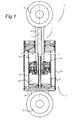
- Fig. 1 the damper according to the present invention is denoted overall by reference numeral 1.
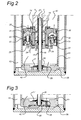
- Fig. 2 shows details of this damper. It consists of a cylinder part 3 into which and out of which a piston part 2 can be moved.
- Reference numerals 4 and 5 denote attachment means of the cylinder part 3 and piston part 2, respectively. It will be understood that these attachment means can be configured differently, depending on the intended use.
- Attachment means 4 is fitted to the piston rod 6.
- the piston 8 is situated on the other end of the piston rod 6. That part of the piston rod 6 which is situated near the piston 8 is provided with a bore 7.
- a sleeve 13 extends in this bore 7.
- the other end of this sleeve 13 is accommodated in the bottom 35 of the cylinder part 3.
- the cylinder part 3 consists of an inner wall 11 with the above-described bottom 35 and an outer wall 10. Between the inner wall 11 and the outer wall 10, a reservoir 12 is delimited.
- the bottom 35 is also provided with a bottom valve 17 which is configured as a non-return valve.
- the piston divides the cylinder into a first chamber 40 and a second chamber 42.
- the first passage 52 in the piston 8 is provided with a first non-return valve 22 which is configured as characteristic, that is to say that, in order to open it, a certain essential positive pressure is required in the opening direction.
- the initial opening pressure may be, for example, more than 50 bar.
- such a characteristic may have a particular opening characteristic, that is to say that when the pressure acting thereon is increased, the cross-sectional flow-through area is increased in a particular manner.
- a spring assembly 23 acts on this first non-return valve 22 and produces the particular opening characteristic of this non-return valve.
- An auxiliary non-return valve 20 is present which acts in the same direction as the main non-return valve 22, but is configured as a simple non-return valve, that is to say which opens at a relatively low pressure of, for example, 1 bar and, more particularly 0,2 bar.
- a passage 21 is present from which a passage 24 branches off.
- a clearance 14 and in this space the liquid can flow into the inside 16 of the sleeve from passage 24.
- the sleeve is sealed with respect to the piston by means of a seal 15.
- the piston is also provided with a non-return valve which acts in the opposite direction in the second passage 53 and which is referred to as the second non-return valve and is denoted by reference numeral 30.
- the latter is also provided with a spring assembly 31 and this second non-return valve is also configured as characteristic.
- the second non-return valve 30 will be closed and remain closed. Liquid can only flow out of the second chamber 42 via passage 25 and the first main non-return valve 22. After the first main non-return valve 22, the liquid can either enter the first chamber 40 via the auxiliary non-return valve 20 or flow into the inside of the sleeve 16.
- the first flow movement is indicated by arrow 26, while the movement of liquid into the sleeve 13 is indicated by arrow 27.
- the auxiliary non-return valve 20 prevents liquid from flowing from the chamber 40 into the sleeve 16.
- the main non-return valve 22 acts as an obstruction. Liquid can only flow from chamber 40 to chamber 42 via the main non-return valve 30 along arrow 34. Moreover, additional volumes of liquid have to be supplied due to the part of the piston rod leaving the cylinder. This liquid is supplied from the reservoir 12 according to the direction of arrow 28 via a non-return valve 17 which is loaded by a spring 18.
- FIG. 3 A further improvement of the concept described herein can be achieved by means of the embodiment of Fig. 3 .
- This embodiment is identical to the embodiment described with reference to Fig. 1 , apart from the fact that in this case a bottom non-return valve 50 is present.
- This bottom non-return valve 50 only allows a flow in the direction from of the bore 7 into the direction of the reservoir 12.
- This non-return valve 50 is configured as a simple non-return valve, that is to say that it has no particular characteristic and opens at a low pressure. As a result thereof, a return flow from the reservoir 12 into the bore 7 and thus into passage 24, possibly in the direction of the chamber 40 can be prevented.
- bottom non-return valve When such a bottom non-return valve is used, it preferably has a greater stiffness than the second auxiliary non-return valve 20. This means that the bottom non-return valve opens after valve 20 when the pressure is increased.
- Fig. 4 shows a variant of the above-described piston 8 which is denoted overall by reference numeral 108.
- a single annular chamber 150 is provided which is connected to chambers 140 and 142, respectively, via a number of openings 152 and 153, respectively.
- This chamber 150 is divided into different parts by means of ring valves 122 and 130, with ring valve 122 providing the characteristic attenuation or damping when the piston moves to the bottom of the cylinder (not shown) and the ring valve 130 providing the characteristic attenuation during the reverse movement.
- the space situated between these ring valves is denoted by reference numeral 121.
- auxiliary non-return valve which cooperates with the ring valve 122 is denoted by reference numeral 120, while an auxiliary non-return valve 125 cooperates with ring valve 130.
- the space 121 is connected to the sleeve 116.
- the space 121 is an unpressurized space during the inward stroke of the piston rod.
- a connection to the sleeve 116 also exists during the return movement where the assembly consisting of valves 130 and 125 becomes active.
- a further embodiment of the damper is shown.
- This is generally referred to by 61 and comprises a piston part 62 enclosed in a cylindrical part 63.
- This cylindrical part 63 is the outer boundary of the damper because a reservoir 72 is delimited at the lower end of cylinder part 63. To that end bottom 85 is fixedly connected to cylinder part 3. The space there below (as seen in the drawing) delimits the reservoir 72.
- the upper part of the reservoir is indicated by 73 whilst lower part indicated with 74 is separated through a movable disc shaped piston 75 there from. Space 74 is filled with a gas whilst space 73 is filled with the damping liquid.
- damper 61 corresponds to what is shown referring to Figs. 1-4 with the exception that reservoir 12 is replaced by reservoir 72 and more particular part 73 thereof.
- the connections to the reservoir 73 are the same as the connections to reservoir 12 in the previous embodiments.
- the damper would not only be used for railway purposes for example between bogey's but also adapted for use for damping (vertical) wheel movements in any kind of vehicle. Although positioning of the damper is preferably horizontal in special embodiments also the direction of the centre line of the piston rod might be in a direction different from horizontal.
Description
- The present invention relates to a damper comprising a cylinder provided with a first attachment means and a piston which can be displaced therein and which is fitted on a hollow piston rod with a second attachment means, wherein said cylinder is divided into a first chamber and a second chamber by said piston, wherein a passage for damping fluid from the second chamber to said first chamber is present, in which passage a first main non-return valve limiting the flow of damping fluid is present, wherein said second chamber comprises the bottom of said cylinder, wherein a liquid reservoir is present which is in fluid connection with said second chamber, wherein a non-return valve is present in said fluid connection and blocks the flow from said second chamber to said liquid reservoir, a sleeve extends from said bottom, which sleeve is in fluid communication with said liquid reservoir and wherein a connection from said first chamber to said cavity via the piston is present downstream of said first main non-return valve when the piston is moved to the bottom of said cylinder.
- A damper of this type is suitable for many applications, one of which is the use in railway applications and, more particularly, in attenuating the rotating movement of a wheel set with respect to the carriage body. Particularly with railway carriages travelling at high speeds, it is important to effectively attenuate the slight mutual movements between the wheel set and the carriage body at high speeds. To this end, it is important that the damper which is used is relatively stiff at high frequencies (such as from 6-8 Hz) and low speeds, that is to say that there is as little gas as possible present in the hydraulic fluid used.
-
GB 2,159,604 Claim 1. - It is an object of the present invention to provide a damper by means of which the above-described desired stiffness can be achieved.
- This object is achieved in a damper having the features of
claim 1. - According to the present invention, there is an "unpressurized" space between the first and second chamber in the passage delimited by the two non-return valves. As a result thereof, it is, on the one hand, possible to freely discharge oil to the reservoir during the inward movement in order to compensate for the piston rod volume and, on the other hand, the pressure in the chambers can be kept relatively high in order to improve the stiffness of the damper.
- The attenuating movement upon displacement of the piston away from the bottom of the cylinder can be achieved by means of a second (main) non-return valve which is present in the piston.
- In particular, the first and second non-return valves are configured as "characteristic". This means that, in contrast to a simple non-return valve which only has to prevent return flow, the non-return valves which are configured as characteristic will only open in the desired direction of flow after a certain, essential threshold value has been exceeded. In other words, the extent to which such a (main) non-return valve opens depends on the flow through such a valve. In addition, it is possible to influence the manner of opening with respect to the build-up of pressure by means of a particular implementation of the spring load on such a non-return valve. By way of example, a gradual opening in the range of, for example, 2-50 bar is mentioned, with such non-return valves functioning as characteristic opening in the direction of flow. Of course, these valves are closed in the other direction.
- During the inward movement of the piston in the cylinder, the reduction in the volume of the second chamber will not be equal to the increase in volume of the first chamber, since an increasingly larger part of the piston rod moves into the first chamber. This means that this volume has to be compensated for. According to the invention, this is achieved by removing such volume via the sleeve in the reservoir. When the piston is moved back out of the cylinder again, the "shortfall in volume" which is caused by the piston rod being moved out of the cylinder will be compensated for by liquid which flows from the reservoir into the second chamber via the bottom valve. By fitting the discharge for excess liquid during the inward movement downstream of the non-return valve which is configured as characteristic, the liquid in the second chamber can be brought to and kept at an elevated pressure. This pressure only changes during the outward movement, when liquid has to be moved from the reservoir via the bottom valve. In this case, the second non-return valve which is preferably configured as characteristic can maintain a positive pressure in the first chamber.
- According to the invention, the first non-return valve is composed of two valves, being a main non-return valve and an auxiliary non-return valve, which are in line with one another. The auxiliary non-return valve may be configures as a conventional non-return valve, that is to say a non-return valve which opens at a slight positive pressure (for example 1 bar or less), while the main non-return valve may be configured as characteristic. The flow connection to the sleeve via the cavity provided in the piston/piston rod takes place downstream of the main non-return valve and upstream of the auxiliary non-return valve, that is to say from the connection between these two valves.
- Such a structure can also be used for the second passage, that is to say the passage through which fluid moves when the piston moves away from the bottom of the cylinder. It is likewise possible for a direct connection to exist to the sleeve in a second passage in the above-described manner. In addition, according to a further advantageous embodiment, it is possible to configure the first and second passage as an (annular) chamber.
- The reservoir may be coupled in any conceivable manner to both the bottom valve and the sleeve. According to a particularly simple embodiment, the first damper is configured as a two-pipe damper, as a result of which the reservoir is situated centrically with respect to the cylinder of the damper.
- According to another preferred embodiment the shock absorber comprises a single tube and the reservoir is positioned downstream from the piston. In a more preferred embodiment this reservoir can be a gas pressurized reservoir.
- According to a further particular embodiment, a non-return valve which prevents a return flow from the reservoir through the sleeve is provided in the connection downstream (inward stroke) of the first non-return valve and the reservoir via the sleeve. Such a non-return valve may be configured as a bottom non-return valve, but it will be understood that it can be provided at any location on the above-described path.
- According to a particular embodiment of this structure, wherein the first non-return valve is, in addition, composed of two non-return valves, one of which non-return valves is a simple non-return valve or auxiliary non-return valve, this first auxiliary non-return valve opens at a lower positive pressure than the non-return valve which has just been described and which may be configured as a bottom non-return valve. This means that during the inward stroke, initially, as large a volume as possible will flow from the second to the first chamber and only when a certain positive pressure is reached in the first chamber will the excess volume of liquid flow into the reservoir via the sleeve and the above-described bottom non-return valve.
- With the application of a railway damper between a wheel set and a carriage body which is described above by way of example, the shock-absorbing means are preferably configured to be symmetrical. It will be understood that the damper can also be used for other purposes, in which case the shock-absorbing characteristics of the inward stroke differ from those of the outward stroke. This can partly be regulated by the spring assemblies acting on the non-return valves and by adapting or adjusting the flow-through openings used and the surfaces subjected to pressure, respectively.
- By means of the invention, it is possible to adapt, starting from a single damper concept, by means of simple modifications which relate, in particular, to the piston and the non-return valves provided therein, to different requirements. In addition, it is possible to use a relatively slim piston rod. Moreover, the non-return valves employed, and more particularly the non-return valves which have a characteristic, can be set on a flow bench in advance, as a result of which the damper can be delivered as a completely set unit.
- The combination of a main non-return valve and an associated seat may be a unit which can be fitted separately and which may be set in advance as a unit. This makes fitting and servicing of such dampers simple.
- The invention will be described below by means of exemplary embodiments illustrated in the drawing, in which:
-
Fig. 1 shows a cross section of a first embodiment of the invention; -
Fig. 2 shows a detail of the embodiment fromFig. 1 ; -
Fig. 3 shows a detail of a second embodiment of the invention; -
Fig. 4 shows a further variant of the invention, and -
Fig. 5 shows a further embodiment of the invention. - In
Fig. 1 , the damper according to the present invention is denoted overall byreference numeral 1.Fig. 2 shows details of this damper. It consists of acylinder part 3 into which and out of which apiston part 2 can be moved.Reference numerals cylinder part 3 andpiston part 2, respectively. It will be understood that these attachment means can be configured differently, depending on the intended use. - Attachment means 4 is fitted to the piston rod 6. The
piston 8 is situated on the other end of the piston rod 6. That part of the piston rod 6 which is situated near thepiston 8 is provided with abore 7. Asleeve 13 extends in thisbore 7. The other end of thissleeve 13 is accommodated in thebottom 35 of thecylinder part 3. Thecylinder part 3 consists of aninner wall 11 with the above-describedbottom 35 and anouter wall 10. Between theinner wall 11 and theouter wall 10, areservoir 12 is delimited. Thebottom 35 is also provided with abottom valve 17 which is configured as a non-return valve. The piston divides the cylinder into afirst chamber 40 and asecond chamber 42. - The first passage 52 in the
piston 8 is provided with a firstnon-return valve 22 which is configured as characteristic, that is to say that, in order to open it, a certain essential positive pressure is required in the opening direction. The initial opening pressure may be, for example, more than 50 bar. In addition, such a characteristic may have a particular opening characteristic, that is to say that when the pressure acting thereon is increased, the cross-sectional flow-through area is increased in a particular manner. Aspring assembly 23 acts on this firstnon-return valve 22 and produces the particular opening characteristic of this non-return valve. - An auxiliary
non-return valve 20 is present which acts in the same direction as the mainnon-return valve 22, but is configured as a simple non-return valve, that is to say which opens at a relatively low pressure of, for example, 1 bar and, more particularly 0,2 bar. - Between these two non-return valves, a
passage 21 is present from which apassage 24 branches off. Between the outer side of thesleeve 13 and thebore 7, there is aclearance 14 and in this space, the liquid can flow into the inside 16 of the sleeve frompassage 24. - The sleeve is sealed with respect to the piston by means of a
seal 15. - The piston is also provided with a non-return valve which acts in the opposite direction in the second passage 53 and which is referred to as the second non-return valve and is denoted by
reference numeral 30. The latter is also provided with aspring assembly 31 and this second non-return valve is also configured as characteristic. - The above-described damper operates as follows:
- During the inward stroke of the piston, the second
non-return valve 30 will be closed and remain closed. Liquid can only flow out of thesecond chamber 42 viapassage 25 and the first mainnon-return valve 22. After the first mainnon-return valve 22, the liquid can either enter thefirst chamber 40 via the auxiliarynon-return valve 20 or flow into the inside of thesleeve 16. The first flow movement is indicated byarrow 26, while the movement of liquid into thesleeve 13 is indicated byarrow 27. As a result of this embodiment, the volume reduction which is caused by the fact that an increasingly larger part of the piston rod 6 which is moving therein is accommodated therein can be compensated for by liquid flowing into thereservoir 12 viasleeve 13. - During the return movement, the auxiliary
non-return valve 20 prevents liquid from flowing from thechamber 40 into thesleeve 16. In addition, the mainnon-return valve 22 acts as an obstruction. Liquid can only flow fromchamber 40 tochamber 42 via the mainnon-return valve 30 alongarrow 34. Moreover, additional volumes of liquid have to be supplied due to the part of the piston rod leaving the cylinder. This liquid is supplied from thereservoir 12 according to the direction ofarrow 28 via anon-return valve 17 which is loaded by aspring 18. - A further improvement of the concept described herein can be achieved by means of the embodiment of
Fig. 3 . This embodiment is identical to the embodiment described with reference toFig. 1 , apart from the fact that in this case a bottomnon-return valve 50 is present. This bottomnon-return valve 50 only allows a flow in the direction from of thebore 7 into the direction of thereservoir 12. Thisnon-return valve 50 is configured as a simple non-return valve, that is to say that it has no particular characteristic and opens at a low pressure. As a result thereof, a return flow from thereservoir 12 into thebore 7 and thus intopassage 24, possibly in the direction of thechamber 40 can be prevented. - When such a bottom non-return valve is used, it preferably has a greater stiffness than the second auxiliary
non-return valve 20. This means that the bottom non-return valve opens aftervalve 20 when the pressure is increased. -
Fig. 4 shows a variant of the above-describedpiston 8 which is denoted overall byreference numeral 108. Instead of a first passage indicated byarrow 26 and a second passage indicated byarrow 34 which are physically separated from one another, in this case a singleannular chamber 150 is provided which is connected tochambers openings chamber 150 is divided into different parts by means ofring valves ring valve 122 providing the characteristic attenuation or damping when the piston moves to the bottom of the cylinder (not shown) and thering valve 130 providing the characteristic attenuation during the reverse movement. The space situated between these ring valves is denoted byreference numeral 121. An auxiliary non-return valve which cooperates with thering valve 122 is denoted byreference numeral 120, while an auxiliarynon-return valve 125 cooperates withring valve 130. As in the previous example, thespace 121 is connected to thesleeve 116. - This means that, compared to the variant described earlier, the
space 121 is an unpressurized space during the inward stroke of the piston rod. However, a connection to thesleeve 116 also exists during the return movement where the assembly consisting ofvalves - In
fig. 5 a further embodiment of the damper is shown. This is generally referred to by 61 and comprises apiston part 62 enclosed in acylindrical part 63. Thiscylindrical part 63 is the outer boundary of the damper because areservoir 72 is delimited at the lower end ofcylinder part 63. To that end bottom 85 is fixedly connected tocylinder part 3. The space there below (as seen in the drawing) delimits thereservoir 72. The upper part of the reservoir is indicated by 73 whilst lower part indicated with 74 is separated through a movable disc shapedpiston 75 there from.Space 74 is filled with a gas whilstspace 73 is filled with the damping liquid. - Basically the further structure of the
damper 61 corresponds to what is shown referring toFigs. 1-4 with the exception thatreservoir 12 is replaced byreservoir 72 and moreparticular part 73 thereof. The connections to thereservoir 73 are the same as the connections toreservoir 12 in the previous embodiments. - It is noticed that both in
reservoir 12 and inreservoir 73 only a relatively low pressure is present. I.e. the high pressure which results from damper movements will not be transferred to eitherreservoir 12 orreservoir 73. In case of the presence of a gas filled damper such as shown inFig. 5 this means that the gas filling at 74 should be sufficient for preventing foaming and other undesirable effects in the low pressure fluid of the damper only. Furthermore this means that pressure of the gas at 74 does not substantially effect inward movement of the damper because of the structure chosen. - Upon reading the above, those skilled in the art will immediately be able to think of variants which are covered by the scope of the attached claims and are obvious after having read the above. Furthermore it is emphasized that the damper would not only be used for railway purposes for example between bogey's but also adapted for use for damping (vertical) wheel movements in any kind of vehicle. Although positioning of the damper is preferably horizontal in special embodiments also the direction of the centre line of the piston rod might be in a direction different from horizontal.
Claims (14)
- Damper (1) comprising a cylinder (3) provided with a first attachment means (5), a piston (8) which can be displaced therein and which is fitted on a hollow piston rod (6) with a second attachment means (4), wherein said cylinder (3) is divided into a first chamber (40) and a second chamber (42) by said piston (8), wherein a passage (26) for damping fluid from the second chamber (42) to said first chamber (40) is present, in which passage (26) a first main non-return valve (22) limiting the flow of damping fluid is present, wherein said second chamber comprises the bottom of said cylinder, wherein a liquid reservoir (12) is present which is in fluid connection with said second chamber (42), wherein a non-return valve (17) is present in said fluid connection and blocks the flow from said second chamber (42) to said liquid reservoir (12), a sleeve (13) extends from said bottom (35), which sleeve is in fluid communication with said liquid reservoir (12) and wherein a connection from said second chamber (42) to said sleeve (13) via the piston (8) is present downstream of said first main non-return valve (22) when the piston is moved to the bottom of said cylinder, characterized in that a first auxiliary non-return valve (20) is present in said passage (26), which operates in the same way as the main non-return valve (22) and in that the space (21) between said first main non-return valve and said first auxiliary non-return valve is directly connected to said sleeve (13).
- Damper according to Claim 1, wherein said first non-return valve (20) is a non-return valve which determines the characteristic of said attenuation.
- Damper according to Claim 1 or 2, wherein only a single direct connection is present between said second chamber (42) and said liquid reservoir (12).
- Damper according to one of the preceding claims, wherein the outer side of said sleeve (13) is arranged at a distance (14) from said cavity (7) of said piston and said sleeve (13) with respect to the part of said cavity (7) is sealed (15) with respect to said piston.
- Damper according to one of the preceding claims, wherein a bottom non-return valve (50) which blocks the flow from said reservoir (12) in said sleeve is arranged in the connection between the sleeve (13) and the reservoir (12).
- Damper according to Claims 4 and 6, wherein said bottom non-return valve (50) opens at a higher positive pressure than said first auxiliary non-return valve (20).
- Damper according to one of the preceding claims, comprising a passage (53) for damping fluid from said first chamber (40) to said second chamber (42), in which passage (53) a second non-return valve (30) is present which limits the flow of damping fluid.
- Damper according to Claim 7, wherein said non-return valves (22, 30) are configured in such a manner that the inward attenuation of said damper is approximately equal to the outward attenuation of said damper.
- Damper according to one of the preceding claims, wherein said (main) non-return valves comprise a valve seat and valve body which form a unit.
- Damper according to one of the preceding claims comprising a railway damper.
- Damper according to Claim 9, arranged between a wheel set and a carriage body of a railway carriage.
- Damper according to one of the preceding claims, wherein said reservoir (12) is defined between the cylinder (3) and an outer wall (10) being provided there around.
- Damper according to one of the preceding claims, wherein said reservoir (12) is defined in an extension (72) of said cylinder.
- Damper according to one of the preceding claims, wherein said reservoir (72) comprises a damping liquid chamber (73) and a pressurized gas chamber (74) separated by a moveable gas and liquid tight separation (75).
Priority Applications (1)
| Application Number | Priority Date | Filing Date | Title |
|---|---|---|---|
| PL11151945T PL2348227T3 (en) | 2010-01-25 | 2011-01-25 | Stiff damper |
Applications Claiming Priority (1)
| Application Number | Priority Date | Filing Date | Title |
|---|---|---|---|
| NL2004138A NL2004138C2 (en) | 2010-01-25 | 2010-01-25 | STIFF DAMPER. |
Publications (2)
| Publication Number | Publication Date |
|---|---|
| EP2348227A1 EP2348227A1 (en) | 2011-07-27 |
| EP2348227B1 true EP2348227B1 (en) | 2013-01-09 |
Family
ID=42668098
Family Applications (1)
| Application Number | Title | Priority Date | Filing Date |
|---|---|---|---|
| EP11151945A Active EP2348227B1 (en) | 2010-01-25 | 2011-01-25 | Stiff damper |
Country Status (9)
| Country | Link |
|---|---|
| US (1) | US8794406B2 (en) |
| EP (1) | EP2348227B1 (en) |
| CN (1) | CN102141105B (en) |
| BR (1) | BRPI1100738A2 (en) |
| DK (1) | DK2348227T3 (en) |
| ES (1) | ES2402352T3 (en) |
| NL (1) | NL2004138C2 (en) |
| PL (1) | PL2348227T3 (en) |
| PT (1) | PT2348227E (en) |
Families Citing this family (14)
| Publication number | Priority date | Publication date | Assignee | Title |
|---|---|---|---|---|
| CN103089892A (en) * | 2011-11-01 | 2013-05-08 | 成都红美金属制品有限公司 | Damper for damping vehicle vibration |
| CN102425081A (en) * | 2011-12-10 | 2012-04-25 | 中铁第一勘察设计院集团有限公司 | Span beam seam slip damping ballastless slab |
| US10113604B2 (en) * | 2012-03-09 | 2018-10-30 | Fox Factory, Inc. | Suspension damper |
| NL2010038C2 (en) | 2012-12-21 | 2014-06-24 | Koni Bv | Shock absorber. |
| FR3003619B1 (en) * | 2013-03-25 | 2015-03-27 | Peugeot Citroen Automobiles Sa | HYDRAULIC SHOCK ABSORBER COMPRISING A FAST RELIEF DEVICE |
| CN105102848B (en) * | 2013-03-29 | 2018-10-30 | 株式会社昭和 | Pressure buffer device |
| FR3006730B1 (en) * | 2013-06-06 | 2015-06-26 | Peugeot Citroen Automobiles Sa | DAMPER WITH HYDRAULIC DAMPING AT THE END OF THE RACE |
| CN104088948B (en) * | 2014-06-26 | 2016-01-06 | 陈东卫 | A kind of carplane buffer |
| ES2696800B2 (en) * | 2017-07-17 | 2019-06-21 | Gimeno Manuel Carcare | Shock absorber cylinder. |
| KR101993645B1 (en) * | 2017-10-31 | 2019-06-26 | 충북대학교 산학협력단 | Linear type one-way damper |
| KR101973696B1 (en) * | 2017-11-03 | 2019-04-30 | 인하대학교 산학협력단 | Mr fluid damper using permanent magnet |
| US11391340B2 (en) * | 2019-02-14 | 2022-07-19 | Goodrich Corporation | Non-metallic orifice plate with metallic wear insert |
| US11781611B2 (en) * | 2021-11-23 | 2023-10-10 | DRiV Automotive Inc. | Damper with compression damping force range increase |
| CN115045948A (en) * | 2022-05-31 | 2022-09-13 | 集美大学 | Dual loss reduction structure of magnetorheological fluid damper |
Family Cites Families (10)
| Publication number | Priority date | Publication date | Assignee | Title |
|---|---|---|---|---|
| US3892298A (en) * | 1974-02-13 | 1975-07-01 | Leland F Blatt | Variable orifice shock absorber |
| FR2541413B1 (en) * | 1983-02-18 | 1988-01-08 | Creusot Loire | SEALING DEVICE FOR TELESCOPIC TYPE HYDRAULIC ENERGY DISSIPATOR |
| DE3419879A1 (en) * | 1984-05-28 | 1985-11-28 | Boge Gmbh, 5208 Eitorf | HYDRAULIC, ADJUSTABLE TWO-TUBE SHOCK ABSORBER |
| NL8800882A (en) * | 1988-04-06 | 1989-11-01 | Koni Bv | TWO-PIPE SHOCK ABSORBER. |
| NL9002878A (en) * | 1990-12-27 | 1992-07-16 | Koni Bv | TWO-PIPE SHOCK ABSORBER. |
| DE59207680D1 (en) * | 1991-03-13 | 1997-01-23 | Teves Gmbh Alfred | TWO TUBE SHOCK ABSORBER |
| JP3700958B2 (en) * | 1996-11-08 | 2005-09-28 | カヤバ工業株式会社 | Vehicle height adjustment device |
| GB2355779B (en) * | 1999-10-25 | 2002-12-24 | Oleo Internat Ltd | A hydro-pneumatic cushioning device |
| JP2008190691A (en) * | 2007-02-07 | 2008-08-21 | Hitachi Ltd | Hydraulic shock absorber |
| JP2009014019A (en) * | 2007-06-29 | 2009-01-22 | Hitachi Ltd | Shock absorber |
-
2010
- 2010-01-25 NL NL2004138A patent/NL2004138C2/en not_active IP Right Cessation
-
2011
- 2011-01-25 US US13/012,826 patent/US8794406B2/en active Active
- 2011-01-25 CN CN201110071732.6A patent/CN102141105B/en active Active
- 2011-01-25 ES ES11151945T patent/ES2402352T3/en active Active
- 2011-01-25 PL PL11151945T patent/PL2348227T3/en unknown
- 2011-01-25 EP EP11151945A patent/EP2348227B1/en active Active
- 2011-01-25 BR BRPI1100738-9A patent/BRPI1100738A2/en not_active Application Discontinuation
- 2011-01-25 PT PT111519450T patent/PT2348227E/en unknown
- 2011-01-25 DK DK11151945.0T patent/DK2348227T3/en active
Also Published As
| Publication number | Publication date |
|---|---|
| PL2348227T3 (en) | 2013-05-31 |
| NL2004138C2 (en) | 2011-07-26 |
| PT2348227E (en) | 2013-03-26 |
| CN102141105A (en) | 2011-08-03 |
| CN102141105B (en) | 2015-12-16 |
| BRPI1100738A2 (en) | 2012-09-04 |
| US20110180361A1 (en) | 2011-07-28 |
| US8794406B2 (en) | 2014-08-05 |
| ES2402352T3 (en) | 2013-04-30 |
| DK2348227T3 (en) | 2013-04-15 |
| EP2348227A1 (en) | 2011-07-27 |
Similar Documents
| Publication | Publication Date | Title |
|---|---|---|
| EP2348227B1 (en) | Stiff damper | |
| EP3039312B1 (en) | Shock absorber with frequency dependent passive valve | |
| JP5710048B2 (en) | Damper with digital valve | |
| US7950506B2 (en) | Semi third tube design | |
| US8511447B2 (en) | Triple tube shock absorber having a shortened intermediate tube | |
| US9994239B2 (en) | Vehicle with force-controlled shock absorber (2-pipe shock absorber) | |
| US9371882B2 (en) | Shock absorber | |
| CN107636344A (en) | Hydraulic compression stop dog component for the hydraulic damper of vehicle suspension | |
| US20140311841A1 (en) | Velocity progressive valving | |
| EP2764274B1 (en) | Fluid-filled, frequency-dependent damper | |
| CN113840990B (en) | Hydraulic compression stop with offset piston | |
| US20170284495A1 (en) | Shock absorber | |
| JP6454536B2 (en) | Shock absorber | |
| US8042791B2 (en) | Self-pumping hydropneumatic shock absorber | |
| US8627933B2 (en) | Two stage valve and hydraulic damped valve | |
| EP2213488B1 (en) | Yaw damper with pump | |
| CN210769980U (en) | Buffer, shock absorber and vehicle | |
| WO2018220202A1 (en) | Pressurized telescopic front fork leg, front fork and vehicle | |
| JP2009078721A (en) | Hydraulic damper | |
| CN205298390U (en) | Hydraulic shock absorber | |
| CN116066503A (en) | Hydraulic damper, shock absorber and vehicle |
Legal Events
| Date | Code | Title | Description |
|---|---|---|---|
| PUAI | Public reference made under article 153(3) epc to a published international application that has entered the european phase |
Free format text: ORIGINAL CODE: 0009012 |
|
| AK | Designated contracting states |
Kind code of ref document: A1 Designated state(s): AL AT BE BG CH CY CZ DE DK EE ES FI FR GB GR HR HU IE IS IT LI LT LU LV MC MK MT NL NO PL PT RO RS SE SI SK SM TR |
|
| AX | Request for extension of the european patent |
Extension state: BA ME |
|
| 17P | Request for examination filed |
Effective date: 20111116 |
|
| GRAP | Despatch of communication of intention to grant a patent |
Free format text: ORIGINAL CODE: EPIDOSNIGR1 |
|
| RIC1 | Information provided on ipc code assigned before grant |
Ipc: F16F 9/06 20060101AFI20120713BHEP Ipc: F16F 9/18 20060101ALI20120713BHEP Ipc: B61G 11/12 20060101ALI20120713BHEP |
|
| GRAS | Grant fee paid |
Free format text: ORIGINAL CODE: EPIDOSNIGR3 |
|
| GRAA | (expected) grant |
Free format text: ORIGINAL CODE: 0009210 |
|
| AK | Designated contracting states |
Kind code of ref document: B1 Designated state(s): AL AT BE BG CH CY CZ DE DK EE ES FI FR GB GR HR HU IE IS IT LI LT LU LV MC MK MT NL NO PL PT RO RS SE SI SK SM TR |
|
| REG | Reference to a national code |
Ref country code: GB Ref legal event code: FG4D |
|
| REG | Reference to a national code |
Ref country code: CH Ref legal event code: EP Ref country code: AT Ref legal event code: REF Ref document number: 592934 Country of ref document: AT Kind code of ref document: T Effective date: 20130115 |
|
| REG | Reference to a national code |
Ref country code: IE Ref legal event code: FG4D |
|
| REG | Reference to a national code |
Ref country code: NL Ref legal event code: T3 |
|
| REG | Reference to a national code |
Ref country code: DE Ref legal event code: R096 Ref document number: 602011000676 Country of ref document: DE Effective date: 20130314 |
|
| REG | Reference to a national code |
Ref country code: PT Ref legal event code: SC4A Free format text: AVAILABILITY OF NATIONAL TRANSLATION Effective date: 20130315 |
|
| REG | Reference to a national code |
Ref country code: RO Ref legal event code: EPE |
|
| REG | Reference to a national code |
Ref country code: DK Ref legal event code: T3 |
|
| REG | Reference to a national code |
Ref country code: SE Ref legal event code: TRGR |
|
| REG | Reference to a national code |
Ref country code: ES Ref legal event code: FG2A Ref document number: 2402352 Country of ref document: ES Kind code of ref document: T3 Effective date: 20130430 |
|
| REG | Reference to a national code |
Ref country code: GR Ref legal event code: EP Ref document number: 20130400550 Country of ref document: GR Effective date: 20130418 |
|
| REG | Reference to a national code |
Ref country code: NO Ref legal event code: T2 Effective date: 20130109 |
|
| PG25 | Lapsed in a contracting state [announced via postgrant information from national office to epo] |
Ref country code: SI Free format text: LAPSE BECAUSE OF FAILURE TO SUBMIT A TRANSLATION OF THE DESCRIPTION OR TO PAY THE FEE WITHIN THE PRESCRIBED TIME-LIMIT Effective date: 20130109 |
|
| REG | Reference to a national code |
Ref country code: PL Ref legal event code: T3 |
|
| REG | Reference to a national code |
Ref country code: LT Ref legal event code: MG4D |
|
| PG25 | Lapsed in a contracting state [announced via postgrant information from national office to epo] |
Ref country code: LT Free format text: LAPSE BECAUSE OF FAILURE TO SUBMIT A TRANSLATION OF THE DESCRIPTION OR TO PAY THE FEE WITHIN THE PRESCRIBED TIME-LIMIT Effective date: 20130109 Ref country code: IS Free format text: LAPSE BECAUSE OF FAILURE TO SUBMIT A TRANSLATION OF THE DESCRIPTION OR TO PAY THE FEE WITHIN THE PRESCRIBED TIME-LIMIT Effective date: 20130509 |
|
| PG25 | Lapsed in a contracting state [announced via postgrant information from national office to epo] |
Ref country code: LV Free format text: LAPSE BECAUSE OF FAILURE TO SUBMIT A TRANSLATION OF THE DESCRIPTION OR TO PAY THE FEE WITHIN THE PRESCRIBED TIME-LIMIT Effective date: 20130109 Ref country code: MC Free format text: LAPSE BECAUSE OF NON-PAYMENT OF DUE FEES Effective date: 20130131 |
|
| PG25 | Lapsed in a contracting state [announced via postgrant information from national office to epo] |
Ref country code: HR Free format text: LAPSE BECAUSE OF FAILURE TO SUBMIT A TRANSLATION OF THE DESCRIPTION OR TO PAY THE FEE WITHIN THE PRESCRIBED TIME-LIMIT Effective date: 20130109 Ref country code: RS Free format text: LAPSE BECAUSE OF FAILURE TO SUBMIT A TRANSLATION OF THE DESCRIPTION OR TO PAY THE FEE WITHIN THE PRESCRIBED TIME-LIMIT Effective date: 20130109 |
|
| REG | Reference to a national code |
Ref country code: IE Ref legal event code: MM4A |
|
| REG | Reference to a national code |
Ref country code: HU Ref legal event code: AG4A Ref document number: E016928 Country of ref document: HU |
|
| PG25 | Lapsed in a contracting state [announced via postgrant information from national office to epo] |
Ref country code: EE Free format text: LAPSE BECAUSE OF FAILURE TO SUBMIT A TRANSLATION OF THE DESCRIPTION OR TO PAY THE FEE WITHIN THE PRESCRIBED TIME-LIMIT Effective date: 20130109 Ref country code: SK Free format text: LAPSE BECAUSE OF FAILURE TO SUBMIT A TRANSLATION OF THE DESCRIPTION OR TO PAY THE FEE WITHIN THE PRESCRIBED TIME-LIMIT Effective date: 20130109 |
|
| PLBE | No opposition filed within time limit |
Free format text: ORIGINAL CODE: 0009261 |
|
| STAA | Information on the status of an ep patent application or granted ep patent |
Free format text: STATUS: NO OPPOSITION FILED WITHIN TIME LIMIT |
|
| PG25 | Lapsed in a contracting state [announced via postgrant information from national office to epo] |
Ref country code: CY Free format text: LAPSE BECAUSE OF FAILURE TO SUBMIT A TRANSLATION OF THE DESCRIPTION OR TO PAY THE FEE WITHIN THE PRESCRIBED TIME-LIMIT Effective date: 20130109 |
|
| 26N | No opposition filed |
Effective date: 20131010 |
|
| PG25 | Lapsed in a contracting state [announced via postgrant information from national office to epo] |
Ref country code: IE Free format text: LAPSE BECAUSE OF NON-PAYMENT OF DUE FEES Effective date: 20130125 Ref country code: AL Free format text: LAPSE BECAUSE OF FAILURE TO SUBMIT A TRANSLATION OF THE DESCRIPTION OR TO PAY THE FEE WITHIN THE PRESCRIBED TIME-LIMIT Effective date: 20130109 |
|
| REG | Reference to a national code |
Ref country code: DE Ref legal event code: R097 Ref document number: 602011000676 Country of ref document: DE Effective date: 20131010 |
|
| PG25 | Lapsed in a contracting state [announced via postgrant information from national office to epo] |
Ref country code: MT Free format text: LAPSE BECAUSE OF FAILURE TO SUBMIT A TRANSLATION OF THE DESCRIPTION OR TO PAY THE FEE WITHIN THE PRESCRIBED TIME-LIMIT Effective date: 20130109 |
|
| PG25 | Lapsed in a contracting state [announced via postgrant information from national office to epo] |
Ref country code: SM Free format text: LAPSE BECAUSE OF FAILURE TO SUBMIT A TRANSLATION OF THE DESCRIPTION OR TO PAY THE FEE WITHIN THE PRESCRIBED TIME-LIMIT Effective date: 20130109 |
|
| PG25 | Lapsed in a contracting state [announced via postgrant information from national office to epo] |
Ref country code: MK Free format text: LAPSE BECAUSE OF FAILURE TO SUBMIT A TRANSLATION OF THE DESCRIPTION OR TO PAY THE FEE WITHIN THE PRESCRIBED TIME-LIMIT Effective date: 20130109 Ref country code: LU Free format text: LAPSE BECAUSE OF NON-PAYMENT OF DUE FEES Effective date: 20130125 |
|
| REG | Reference to a national code |
Ref country code: FR Ref legal event code: PLFP Year of fee payment: 6 |
|
| REG | Reference to a national code |
Ref country code: FR Ref legal event code: PLFP Year of fee payment: 7 |
|
| REG | Reference to a national code |
Ref country code: FR Ref legal event code: PLFP Year of fee payment: 8 |
|
| PGFP | Annual fee paid to national office [announced via postgrant information from national office to epo] |
Ref country code: PT Payment date: 20200103 Year of fee payment: 10 Ref country code: RO Payment date: 20200110 Year of fee payment: 10 Ref country code: BG Payment date: 20200120 Year of fee payment: 10 Ref country code: GR Payment date: 20200129 Year of fee payment: 10 Ref country code: AT Payment date: 20200102 Year of fee payment: 10 Ref country code: DK Payment date: 20200129 Year of fee payment: 10 Ref country code: NO Payment date: 20200129 Year of fee payment: 10 Ref country code: HU Payment date: 20200110 Year of fee payment: 10 |
|
| PGFP | Annual fee paid to national office [announced via postgrant information from national office to epo] |
Ref country code: TR Payment date: 20200114 Year of fee payment: 10 |
|
| REG | Reference to a national code |
Ref country code: DK Ref legal event code: EBP Effective date: 20210131 |
|
| REG | Reference to a national code |
Ref country code: NO Ref legal event code: MMEP |
|
| REG | Reference to a national code |
Ref country code: AT Ref legal event code: MM01 Ref document number: 592934 Country of ref document: AT Kind code of ref document: T Effective date: 20210125 |
|
| PG25 | Lapsed in a contracting state [announced via postgrant information from national office to epo] |
Ref country code: BG Free format text: LAPSE BECAUSE OF NON-PAYMENT OF DUE FEES Effective date: 20210731 Ref country code: AT Free format text: LAPSE BECAUSE OF NON-PAYMENT OF DUE FEES Effective date: 20210125 Ref country code: HU Free format text: LAPSE BECAUSE OF NON-PAYMENT OF DUE FEES Effective date: 20210126 |
|
| PG25 | Lapsed in a contracting state [announced via postgrant information from national office to epo] |
Ref country code: PT Free format text: LAPSE BECAUSE OF NON-PAYMENT OF DUE FEES Effective date: 20210726 Ref country code: NO Free format text: LAPSE BECAUSE OF NON-PAYMENT OF DUE FEES Effective date: 20210131 Ref country code: RO Free format text: LAPSE BECAUSE OF NON-PAYMENT OF DUE FEES Effective date: 20210125 Ref country code: GR Free format text: LAPSE BECAUSE OF NON-PAYMENT OF DUE FEES Effective date: 20210805 |
|
| PG25 | Lapsed in a contracting state [announced via postgrant information from national office to epo] |
Ref country code: DK Free format text: LAPSE BECAUSE OF NON-PAYMENT OF DUE FEES Effective date: 20210131 |
|
| PGFP | Annual fee paid to national office [announced via postgrant information from national office to epo] |
Ref country code: PL Payment date: 20221222 Year of fee payment: 13 Ref country code: BE Payment date: 20221220 Year of fee payment: 13 |
|
| PGFP | Annual fee paid to national office [announced via postgrant information from national office to epo] |
Ref country code: ES Payment date: 20230201 Year of fee payment: 13 Ref country code: CH Payment date: 20230201 Year of fee payment: 13 |
|
| PGFP | Annual fee paid to national office [announced via postgrant information from national office to epo] |
Ref country code: IT Payment date: 20230103 Year of fee payment: 13 Ref country code: DE Payment date: 20221220 Year of fee payment: 13 |
|
| P01 | Opt-out of the competence of the unified patent court (upc) registered |
Effective date: 20230528 |
|
| PGFP | Annual fee paid to national office [announced via postgrant information from national office to epo] |
Ref country code: GB Payment date: 20231219 Year of fee payment: 14 |
|
| PGFP | Annual fee paid to national office [announced via postgrant information from national office to epo] |
Ref country code: SE Payment date: 20231219 Year of fee payment: 14 Ref country code: NL Payment date: 20231219 Year of fee payment: 14 Ref country code: FR Payment date: 20231219 Year of fee payment: 14 Ref country code: FI Payment date: 20231219 Year of fee payment: 14 Ref country code: CZ Payment date: 20231227 Year of fee payment: 14 |
|
| PGFP | Annual fee paid to national office [announced via postgrant information from national office to epo] |
Ref country code: PL Payment date: 20231221 Year of fee payment: 14 Ref country code: BE Payment date: 20231219 Year of fee payment: 14 |
|
| PGFP | Annual fee paid to national office [announced via postgrant information from national office to epo] |
Ref country code: ES Payment date: 20240202 Year of fee payment: 14 |