EP2348190A2 - Steam turbine power plant - Google Patents
Steam turbine power plant Download PDFInfo
- Publication number
- EP2348190A2 EP2348190A2 EP10195157A EP10195157A EP2348190A2 EP 2348190 A2 EP2348190 A2 EP 2348190A2 EP 10195157 A EP10195157 A EP 10195157A EP 10195157 A EP10195157 A EP 10195157A EP 2348190 A2 EP2348190 A2 EP 2348190A2
- Authority
- EP
- European Patent Office
- Prior art keywords
- turbine
- pressure
- steam
- thrust
- thrust piston
- Prior art date
- Legal status (The legal status is an assumption and is not a legal conclusion. Google has not performed a legal analysis and makes no representation as to the accuracy of the status listed.)
- Granted
Links
Images


Classifications
-
- F—MECHANICAL ENGINEERING; LIGHTING; HEATING; WEAPONS; BLASTING
- F01—MACHINES OR ENGINES IN GENERAL; ENGINE PLANTS IN GENERAL; STEAM ENGINES
- F01K—STEAM ENGINE PLANTS; STEAM ACCUMULATORS; ENGINE PLANTS NOT OTHERWISE PROVIDED FOR; ENGINES USING SPECIAL WORKING FLUIDS OR CYCLES
- F01K23/00—Plants characterised by more than one engine delivering power external to the plant, the engines being driven by different fluids
- F01K23/12—Plants characterised by more than one engine delivering power external to the plant, the engines being driven by different fluids the engines being mechanically coupled
- F01K23/16—Plants characterised by more than one engine delivering power external to the plant, the engines being driven by different fluids the engines being mechanically coupled all the engines being turbines
-
- F—MECHANICAL ENGINEERING; LIGHTING; HEATING; WEAPONS; BLASTING
- F01—MACHINES OR ENGINES IN GENERAL; ENGINE PLANTS IN GENERAL; STEAM ENGINES
- F01D—NON-POSITIVE DISPLACEMENT MACHINES OR ENGINES, e.g. STEAM TURBINES
- F01D3/00—Machines or engines with axial-thrust balancing effected by working-fluid
- F01D3/02—Machines or engines with axial-thrust balancing effected by working-fluid characterised by having one fluid flow in one axial direction and another fluid flow in the opposite direction
-
- F—MECHANICAL ENGINEERING; LIGHTING; HEATING; WEAPONS; BLASTING
- F01—MACHINES OR ENGINES IN GENERAL; ENGINE PLANTS IN GENERAL; STEAM ENGINES
- F01D—NON-POSITIVE DISPLACEMENT MACHINES OR ENGINES, e.g. STEAM TURBINES
- F01D3/00—Machines or engines with axial-thrust balancing effected by working-fluid
- F01D3/04—Machines or engines with axial-thrust balancing effected by working-fluid axial thrust being compensated by thrust-balancing dummy piston or the like
-
- F—MECHANICAL ENGINEERING; LIGHTING; HEATING; WEAPONS; BLASTING
- F05—INDEXING SCHEMES RELATING TO ENGINES OR PUMPS IN VARIOUS SUBCLASSES OF CLASSES F01-F04
- F05D—INDEXING SCHEME FOR ASPECTS RELATING TO NON-POSITIVE-DISPLACEMENT MACHINES OR ENGINES, GAS-TURBINES OR JET-PROPULSION PLANTS
- F05D2220/00—Application
- F05D2220/30—Application in turbines
- F05D2220/31—Application in turbines in steam turbines
Definitions
- This present application relates generally to methods, systems, and/or apparatus for improving the operation of steam turbine engines. More specifically, but not by way of limitation, the present application relates to improved methods, systems, and/or apparatus pertaining to the operation of steam turbines with 3-flow low pressure turbines.
- steam turbine plants may be constructed with a rotor train that, via a common shaft, connects multiple turbines that operate at varying pressure levels.
- each of these turbines is paired with another turbine so that the axial thrust force (or "thrust") being exerted on the shaft by each may be balanced by another.
- a steam turbine plant may include a high-pressure turbine that is paired with an intermediate-pressure turbine.
- these turbines may be configured so that the thrust force each applies to the shaft is offset (or substantially offset) by the thrust the other applies.
- steam turbine plants often have two low-pressure turbines that are paired with each other in the same manner, i.e., so that the thrust each applies to the shaft balances the thrust of the other.
- the present application thus describes a steam turbine power plant that includes a first steam turbine, the steam turbine power plant including: a thrust piston operably connected to the first steam turbine via a shaft; and means for applying a supply of pressurized steam against the thrust piston such that the thrust piston applies a desired thrust force to the shaft.
- the desired thrust force comprises a thrust force that partially balances a thrust force the first steam turbine applies to the shaft during operation.
- the desired thrust force includes a thrust force that balances a thrust force the first steam turbine applies to the shaft during operation.
- the desired thrust force includes a thrust force that at least partially balances a thrust force the first steam turbine applies to the shaft during operation.
- the system may further include a second steam turbine that operates at a higher pressure than the first steam turbine; wherein the supply of pressurized steam is extracted from the second steam turbine.
- the present application further describes a thrust piston in a steam turbine power plant that includes a rotor train including a high-pressure turbine, an intermediate-pressure turbine, and three low-pressure turbines, wherein the three low-pressure turbine include two that include a dual-flow low-pressure turbine and a single-flow low-pressure turbine; wherein the high-pressure turbine and the intermediate-pressure turbine are configured such that each substantially balances the thrust force of the other, and wherein the two low-pressure turbines of the dual-flow low-pressure turbine are configured such that each substantially balances the thrust force of the other; and wherein means for extraction supply high-pressured steam from the high-pressure turbine to a cavity disposed forward of the single-flow low-pressure turbine; and wherein the cavity, in the direction toward the single-flow low pressure turbine, is substantially bound by stationary structure that surrounds a shaft of the rotor train.
- the thrust piston may be connected to the shaft, wherein the cavity, in the direction away from the single-flow low pressure turbine, is substantially bound the thrust piston; and wherein the thrust piston is configured to counteract a desired amount of a thrust force generated by the single-flow low-pressure turbine during operation.
- the thrust piston is configured to counteract substantially all of the thrust force generated by the single-flow low-pressure turbine during operation.
- a surface area of the thrust piston that bounds the cavity is configured to include a size required to counteract substantially all of the thrust force generated by the single-flow low-pressure given the pressure of the high pressure steam that is supplied to the cavity.
- the means for extraction includes an extraction point in the high-pressure steam turbine that provides high-pressure steam to the cavity at a pressure sufficient to counteract substantially all of the thrust force generated by the single-flow low-pressure given a size of the surface area of the thrust piston that bounds the cavity.
- the single-flow low-pressure turbine includes a position adjacent to the exhaust of the high-pressure turbine and the dual-flow low-pressure turbine includes a position adjacent to the exhaust of the intermediate pressure turbine.
- the thrust piston includes a rigid section of the shaft that includes a larger diameter than the shaft; the thrust piston includes the cylindrical shape, the axis of which is aligned with the axis of the shaft; the thrust piston includes a relatively narrow axial thickness and a predetermined circular cross-sectional area; and the predetermined circular cross-sectional area includes a cross-section area required given the desired thrust force to counteract and the pressure level of the high-pressure steam delivered to the cavity.
- the means for extraction includes a first conduit that is configured to extract high-pressure steam from a predetermined stage of the high-pressure turbine.
- a second conduit is configured to direct the high-pressurized steam from the cavity to an aft stage of the high-pressure turbine, the aft stage including a stage that is downstream relative to the predetermined stage where high-pressure steam is extracted.
- the cavity, in the direction toward the single-flow low pressure turbine is further bound by a first plurality of seals, the first plurality of seals being configured to provide a seal between the stationary structure and the shaft; and the cavity, in the direction away from the single-flow low pressure turbine, is further bound by a second plurality of seals, the second plurality of seals being configured to provide a seal between the stationary structure and the thrust piston.
- the shaft includes a clutch that operates to desirably engage and disengaged the single-flow low-pressure turbine from the rotor train.
- the means for extraction when the single-flow low-pressure turbine is engaged by the clutch, the means for extraction operates to supply the high-pressured steam from the high-pressure turbine to the cavity; and when the single-flow low-pressure turbine is disengaged by the clutch, the means for extraction discontinues to supply the high-pressured steam from the high-pressure turbine to the cavity.
- Downstream and upstream are terms that indicate a direction relative to the flow of working fluid through the turbine.
- downstream refers to a direction that generally corresponds to the direction of the flow of working fluid
- upstream generally refers to the direction that is opposite of the direction of flow of working fluid.
- trailing and “leading” generally refers relative position in relation to the direction of rotation for rotating parts.
- the "leading edge” of a rotating part is the front or forward edge given the direction that the part is rotating and, the “trailing edge” of a rotating part is the aft or rearward edge given the direction that the part is rotating.
- the term “radial” refers to movement or position perpendicular to an axis. It is often required to described parts that are at differing radial positions with regard to an axis. In this case, if a first component resides closer to the axis than a second component, it may be stated herein that the first component is “radially inward” or "inboard” of the second component.
- first component resides further from the axis than the second component, it may be stated herein that the first component is “radially outward” or “outboard” of the second component.
- axial refers to movement or position parallel to an axis.
- circumferential refers to movement or position around an axis.
- Figure 1 illustrates a schematic representation of a steam turbine power plant 100 according to a possible conventional layout.
- the steam turbine power plant 100 may include a rotor train that includes several turbines or turbine sections, which, as stated, may be referred to given the relative pressure level of the steam that is directed through each.
- the steam turbine power plant 100 may include a high-pressure turbine ("HP turbine”) 104, which includes a high-pressure steam feed 105, an intermediate-pressure turbine (“IP turbine”) 106, which includes an intermediate-pressure steam feed 107, and three different low-pressure turbines, two of which are part of a dual-flow low-pressure turbine (“dual flow LP turbines”) 108, which includes a low-pressure steam feed 109, and a single-flow low-pressure turbine (“single-flow LP turbine”) 110, which also includes a low-pressure steam feed 109.
- HP turbine high-pressure turbine
- IP turbine intermediate-pressure turbine
- IP turbine intermediate-pressure turbine
- three different low-pressure turbines two of which are part of a dual-flow low-pressure turbine
- dual flow LP turbines dual-flow low-pressure turbine
- single-flow low-pressure turbine single-flow low-pressure turbine
- the steam turbine power plant 100 includes a steam source or boiler (not shown), which provides the supply of pressurized steam that is delivered via the steam feeds 105, 107, 109 to the turbine sections 104, 106, 108, 110.
- a steam source or boiler not shown
- steam supply systems may be configured to include one or more direct or indirect connections made between the boiler and the various turbine sections; or, for example, one or more connections may be made between the output or exhaust of one of the higher pressure turbine sections to the steam feed of one of the lower pressure turbine sections; or, some combination of either of those systems may be used.
- the system may further include one or more re-heaters, pre-heaters, and/or other conventional components and systems.
- the shaft 102 is connected to a generator 112 where the mechanical energy of the rotating shaft is converted into electricity.
- the steam turbine power plant 100 is configured, as shown, such that the HP turbine 104 is paired with the IP turbine 106. It will be understood that the HP turbine 104 and the IP turbine 106 may be configured such that, during operation, the thrust force generated by and asserted to the shaft 102 is offset (or, at least, partially offset) by the thrust the other applies to the shaft 102. In addition, as shown in Figure 1 , the dual-flow LP turbines 108 may be paired with each other in the same manner, i.e., so that the thrust each applies to the shaft balances the thrust of the other.
- the thrust imbalance caused by the single-flow LP turbine 110 would only need to be balanced by the thrust bearing 116 when the single-flow LP turbine 110 was engaged by the clutch 118, which likely means the costly, oversized thrust bearing 116 would only be required during peak demand periods, and rendered superfluous at all other times.
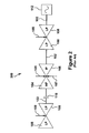
- FIG 2 provides a schematic representation of a steam turbine power plant 200 according to another possible conventional layout.
- the steam turbine power plant 200 includes several turbines that may be referenced given the pressure level of the steam that is directed through each, i.e., a HP turbine 104, which includes a high-pressure steam feed 105, an IP turbine 106, which includes an intermediate-pressure steam feed 107, and four LP turbines (each of which are paired in two dual-flow turbine 108 configurations), each of which includes a low-pressure steam feed 109.
- the steam turbine power plant 200 is configured such that the HP turbine 104 is paired with the IP turbine 106 such that the thrust of each substantially balances the other.
- the two sets of dual-flow LP turbines 108 are paired in the same manner, i.e., so that the thrust each applies to the shaft 102 balances the thrust of the other.
- an additional single-flow LP turbine 110 (as in Figure 1 )
- two additional LP turbines 108 are included, which, via the clutch 118, may be used to address changing load demands by engaging and disengaging the dual-flow LP turbines 108 as necessary.
- the power plant 200 in Figure 2 is not does not allow for the same operational flexibility as the power plant of Figure 1 , as, in most applications, engaging two LP turbines 110 would overshoot the intended target and be inefficient. That is, to meet peak demands, the plant operator of Figure 2 has to activate the two additional LP turbines (i.e., the two that make up the dual-flow LP turbine 108), whereas the plant operator of Figure 1 has the option of activating a single-flow LP turbine 109. As such, in cases where only a single additional LP turbine is required, the power plant 100 of Figure 1 is much more efficient and cost-effective. As discussed above, though, the unbalanced single-flow LP turbine 110 has shortcomings of its own in that it requires a costly thrust bearing 116 to balance thrust forces.
- FIG 3 provides a schematic representation of a steam turbine power plant 300 according to an exemplary embodiment of the present application.
- the steam turbine power plant 300 includes the same steam turbines as those shown in the steam turbine power plant 100 of Figure 1 : a HP turbine 104, which includes a high-pressure steam feed 105, an IP turbine 106, which includes an intermediate-pressure steam feed 107, and three LP turbines 108, 110, including two dual-flow LP turbines 108 and a single-flow LP turbine 110.
- Each of the LP turbine 108, 110 may include a low-pressure steam feed 109, as shown.
- the HP turbine 104 is paired (and generally balanced) with the IP turbine 106, and the two dual-flow LP turbines 108 are paired (and generally balanced) with each other so that the thrust each applies to the shaft balances the thrust of the other engine.
- the single-flow LP turbine 110 cannot be balanced by another turbine. It will be appreciated that when the single-flow LP turbine 110 is operating, it applies a considerable thrust force along the shaft 102 that must be accounted for or balanced in some way.
- Figure 3 includes a schematic representation of the stationary turbine casing or outer structure 125 that surrounds the rotor train in that location. This depiction is provided in that section of the power plant 300 because it is particularly illustrative of the present invention. It will be appreciated that the outer structure 125 represents conventional components and structures known in the art.
- the thrust of the single-flow LP turbine 110 is balanced or, at least, partially balanced, by a thrust piston 128 against which high-pressure steam is applied.
- high-pressure steam acting on a thrust piston 128 that disposed in proximity to and forward of the single-flow LP turbine 110 compensates, or, at least, partially compensates, for the thrust imbalance produced by the single-flow LP turbine 110 when the single-flow LP turbine 110 is operating and engaged.
- the thrust piston 128 may comprise a rigid section of the shaft that enlarged, i.e., has a larger diameter than the shaft 102.
- the thrust piston 128 comprises the cylindrical shape, the axis of which is aligned with the axis of the shaft 102.
- the cylinder generally comprises a relatively narrow axial thickness and a circular cross-sectional area that may be sized based on the particular application, as described in more detail below.
- the thrust piston 128 generally will be constructed from conventional materials.
- the high-pressure steam that is applied to the thrust piston 128 for this purpose may be extracted per conventional means from the HP turbine 104. From the extraction point, the supply of high-pressure steam may be directed via a first conduit 132 from the HP turbine 104 to a cavity 135.
- the cavity 135 is a substantially enclosed space that is disposed between the thrust piston 128 and the single-flow LP turbine 110. In the direction of the single flow LP turbine 110, the cavity 135 is bound by stationary structure 125 and a plurality of seals 137 that form a seal between the stationary structure 125 and the shaft 102.
- the seals 137 may comprise conventional seals that operate to provide a seal between stationary components, which in this case is the stationary structure 125, and rotating components, which in this case is the shaft 102.
- the seals 137 may be brush seals, hi-lo seals, or other types of seals.
- the cavity 135 may be adjacent to and bound by the thrust piston 128 and seals 137 that form a seal between the stationary structure 125 and the thrust piston 128.
- the seals 137 may comprise conventional seals that operate to provide a seal between stationary components, which in this case is the stationary structure 125, and rotating components, which in this case is the outer radial edge of the cylindrical thrust piston 128.
- a second conduit 141 returns the pressurized steam from the cavity 135 to the downstream stages of the HP turbine 104. Thereby returned, the steam may be exhausted into the later stages of the HP turbine 104.
- This configuration may limit the loss of steam to the system.
- the steam from cavity 135 may be used for other purposes also. For example, it may be supplied to the IP turbine or one of the LP turbines, or used in a heating system.
- a clutch 118 may be provided so that the single-flow LP turbine 110 may be engaged when needed and disengaged when load demands are adequately satisfied by the other available turbines of the power plant 300.
- the single-flow LP turbine 110 is disengaged, it will be appreciated there is no net thrust to balance.
- the high-pressure steam supply from the HP turbine 104 may be shut-off, which makes the steam that would have been extracted available to the HP turbine 104.
- the shut-off of the high-pressure steam may be done via a valve 143 or other conventional methods.
- the thrust piston 128 required to balance the single-flow LP turbine 110 may remain relatively compact in size. More particularly, it will be understood that the size of the thrust piston 128 that is required to balance the single-flow LP turbine 110 is dependent upon the pressure of the steam that is supplied to the cavity 135. A lower-pressure supply of steam requires a thrust piston 128 having considerable surface area against which the steam may exert its force.
- a higher-pressure supply of steam requires less surface area against which to push, while still balancing the thrust force of the single-flow LP turbine 110.
- the extraction of the steam from the HP turbine 104 provides the high-pressure supply of steam that allows a relatively small, cost-effective thrust piston 128 to balance the single-flow LP turbine 110.
- a known, convenient extraction point within the HP turbine 104 may available and the thrust piston 128 designed to accommodate that particular extraction point. That is, given the pressure of the steam that may be provided to the cavity 135 from the extraction point and the thrust force of the single-flow LP turbine 110 for which compensation is required, the thrust piston 128 may be designed so that necessary surface area is available.
- the thrust piston 128 may be designed based on other criteria or limitations and the steam extraction point determined based on it. That is, given the thrust force for which compensation is required and the surface area of the thrust piston 128, an extraction location within the HP turbine 104 may be determined which provides steam at the desired pressure to the cavity 135.
- the thrust piston 128 also may be configured so that it balances only a portion of the thrust force created by the single-flow LP turbine 110.
- the thrust piston 128 may be configured to partially balance the thrust of the single-flow LP turbine 110 while thrust bearings 116 are included to provide balance to the system. In these cases, it will be appreciated that the size of the thrust bearings 116 likely would be much reduced, which may make this an attractive alternative in certain applications.
- the single-flow LP turbine 110 may be connected to the shaft 102 adjacent to or near the exhaust of the HP turbine 104, while the dual-flow LP section is connected to the rotor train adjacent to the exhaust of the IP turbine 106, as depicted in Figure 3 .
- this application is exemplary only. It will be appreciated that the same principles may be used to balance the thrust of turbines in other types of power plant configurations.
- the principles provided herein may be used effectively to provide balance to any steam turbine (low pressure or otherwise) in a system that includes a steam turbine that operates at a higher pressure or has another supply of higher pressured steam.
- steam may be extracted from the HP turbine 104 and directed via the conduit 132 to the cavity 135.
- the pressurized steam asserts an axially aligned force in both directions.
- the steam In the direction toward the single-flow LP turbine 110, the steam primarily presses against the stationary structure 125. (A small portion of the steam presses against the seal 137 and a smaller portion escapes through the seals 137.
- the system is configured such that the steam that escapes through the seals 137 enters the single-flow LP turbine 110 where it may be used.)
- the steam within the cavity 135 presses primarily on the thrust piston 128.
- the net effect of the pressure with the cavity 135 is a thrust force being applied on the shaft 102 away from the single-flow LP turbine 110.
- the size of this net force may be configured by varying the surface area of the thrust piston 128 so that a desired portion of the thrust force created by the single-flow LP 110 turbine is counteracted.
Landscapes
- Engineering & Computer Science (AREA)
- Mechanical Engineering (AREA)
- General Engineering & Computer Science (AREA)
- Physics & Mathematics (AREA)
- Fluid Mechanics (AREA)
- Chemical & Material Sciences (AREA)
- Combustion & Propulsion (AREA)
- Control Of Turbines (AREA)
Abstract
Description
- This present application relates generally to methods, systems, and/or apparatus for improving the operation of steam turbine engines. More specifically, but not by way of limitation, the present application relates to improved methods, systems, and/or apparatus pertaining to the operation of steam turbines with 3-flow low pressure turbines.
- As one of ordinary skill in the art will appreciate, steam turbine plants may be constructed with a rotor train that, via a common shaft, connects multiple turbines that operate at varying pressure levels. Typically, each of these turbines is paired with another turbine so that the axial thrust force (or "thrust") being exerted on the shaft by each may be balanced by another. For example, a steam turbine plant may include a high-pressure turbine that is paired with an intermediate-pressure turbine. During operation, these turbines may be configured so that the thrust force each applies to the shaft is offset (or substantially offset) by the thrust the other applies. In addition, steam turbine plants often have two low-pressure turbines that are paired with each other in the same manner, i.e., so that the thrust each applies to the shaft balances the thrust of the other.
- In some cases, however, the thrust forces applied across a rotor train having a common shaft cannot be balanced by pairing turbines. It will be understood that, in such situations, large, expensive thrust bearings generally are required to provide the counteracting forces so that thrust balance is achieved. In some applications, having an odd number of turbines would be advantageous, particularly where one of the turbines could be activated and deactivated depending on load requirements. In this case, the odd number of turbines and/or the fact that one is operated only at peak load periods means thrust balancing would be impossible by simply pairing the turbines to offset similar thrust forces. This system, instead, would have to include a sizable thrust bearing to counteract the force of generated by the part-time turbine when it operated. This solution, however, is not desirable because the cost of constructing and maintaining the thrust bearing is considerable, a fact that is even less palatable considering the thrust bearing is only needed on a part-time basis, i.e., when the part-time turbine is activated.
- As a result, there is a need for improved systems and/or apparatus for balancing rotor thrust in changing operating conditions and, for rotor trains that are difficult to balance because of the varying turbine size and number, particularly where the improvements are cost-effective and simple in both construction and operation.
- The present application thus describes a steam turbine power plant that includes a first steam turbine, the steam turbine power plant including: a thrust piston operably connected to the first steam turbine via a shaft; and means for applying a supply of pressurized steam against the thrust piston such that the thrust piston applies a desired thrust force to the shaft. In some embodiments, the desired thrust force comprises a thrust force that partially balances a thrust force the first steam turbine applies to the shaft during operation. In some embodiments, the desired thrust force includes a thrust force that balances a thrust force the first steam turbine applies to the shaft during operation.
- In some embodiments, the desired thrust force includes a thrust force that at least partially balances a thrust force the first steam turbine applies to the shaft during operation. The system may further include a second steam turbine that operates at a higher pressure than the first steam turbine; wherein the supply of pressurized steam is extracted from the second steam turbine.
- The present application further describes a thrust piston in a steam turbine power plant that includes a rotor train including a high-pressure turbine, an intermediate-pressure turbine, and three low-pressure turbines, wherein the three low-pressure turbine include two that include a dual-flow low-pressure turbine and a single-flow low-pressure turbine; wherein the high-pressure turbine and the intermediate-pressure turbine are configured such that each substantially balances the thrust force of the other, and wherein the two low-pressure turbines of the dual-flow low-pressure turbine are configured such that each substantially balances the thrust force of the other; and wherein means for extraction supply high-pressured steam from the high-pressure turbine to a cavity disposed forward of the single-flow low-pressure turbine; and wherein the cavity, in the direction toward the single-flow low pressure turbine, is substantially bound by stationary structure that surrounds a shaft of the rotor train. The thrust piston may be connected to the shaft, wherein the cavity, in the direction away from the single-flow low pressure turbine, is substantially bound the thrust piston; and wherein the thrust piston is configured to counteract a desired amount of a thrust force generated by the single-flow low-pressure turbine during operation.
- In some embodiments, the thrust piston is configured to counteract substantially all of the thrust force generated by the single-flow low-pressure turbine during operation. In some embodiments, a surface area of the thrust piston that bounds the cavity is configured to include a size required to counteract substantially all of the thrust force generated by the single-flow low-pressure given the pressure of the high pressure steam that is supplied to the cavity.
- In some embodiments, the means for extraction includes an extraction point in the high-pressure steam turbine that provides high-pressure steam to the cavity at a pressure sufficient to counteract substantially all of the thrust force generated by the single-flow low-pressure given a size of the surface area of the thrust piston that bounds the cavity. In some embodiments, the single-flow low-pressure turbine includes a position adjacent to the exhaust of the high-pressure turbine and the dual-flow low-pressure turbine includes a position adjacent to the exhaust of the intermediate pressure turbine.
- In some embodiments, the thrust piston includes a rigid section of the shaft that includes a larger diameter than the shaft; the thrust piston includes the cylindrical shape, the axis of which is aligned with the axis of the shaft; the thrust piston includes a relatively narrow axial thickness and a predetermined circular cross-sectional area; and the predetermined circular cross-sectional area includes a cross-section area required given the desired thrust force to counteract and the pressure level of the high-pressure steam delivered to the cavity.
- In some embodiments, the means for extraction includes a first conduit that is configured to extract high-pressure steam from a predetermined stage of the high-pressure turbine. In some embodiments, a second conduit is configured to direct the high-pressurized steam from the cavity to an aft stage of the high-pressure turbine, the aft stage including a stage that is downstream relative to the predetermined stage where high-pressure steam is extracted.
- In some embodiments, the cavity, in the direction toward the single-flow low pressure turbine, is further bound by a first plurality of seals, the first plurality of seals being configured to provide a seal between the stationary structure and the shaft; and the cavity, in the direction away from the single-flow low pressure turbine, is further bound by a second plurality of seals, the second plurality of seals being configured to provide a seal between the stationary structure and the thrust piston. In some embodiments, the shaft includes a clutch that operates to desirably engage and disengaged the single-flow low-pressure turbine from the rotor train.
- In some embodiments, when the single-flow low-pressure turbine is engaged by the clutch, the means for extraction operates to supply the high-pressured steam from the high-pressure turbine to the cavity; and when the single-flow low-pressure turbine is disengaged by the clutch, the means for extraction discontinues to supply the high-pressured steam from the high-pressure turbine to the cavity.
- These and other features of the present application will become apparent upon review of the following detailed description of the preferred embodiments when taken in conjunction with the drawings and the appended claims.
- These and other features of this invention will be more completely understood and appreciated by careful study of the following more detailed description of exemplary embodiments of the invention taken in conjunction with the accompanying drawings, in which:
-
Figure 1 is a schematic representation of an exemplary steam turbine power plant according to conventional design; -
Figure 2 is a schematic representation of another exemplary steam turbine power plant according to conventional design; and -
Figure 3 is a schematic representation of a steam turbine power plant according to an exemplary embodiment of the present application. - As an initial matter, to communicate clearly the invention of the current application, it may be necessary to select terminology that refers to and describes certain parts or machine components of a turbine engine. Whenever possible, common industry terminology will be used and employed in a manner consistent with its accepted meaning. However, it is meant that any such terminology be given a broad meaning and not narrowly construed such that the meaning intended herein and the scope of the appended claims is unreasonably restricted. Those of ordinary skill in the art will appreciate that often a particular component may be referred to using several different terms. In addition, what may be described herein as a single part may include and be referenced in another context as consisting of several component parts, or, what may be described herein as including multiple component parts may be fashioned into and, in some cases, referred to as a single part. As such, in understanding the scope of the invention described herein, attention should not only be paid to the terminology and description provided, but also to the structure, configuration, function, and/or usage of the component, as provided herein.
- In addition, several descriptive terms may be used regularly herein, and it may be helpful to define these terms at this point. Given their usage herein, these terms and definitions are as follows. "Downstream" and "upstream" are terms that indicate a direction relative to the flow of working fluid through the turbine. As such, the term "downstream" refers to a direction that generally corresponds to the direction of the flow of working fluid, and the term "upstream" generally refers to the direction that is opposite of the direction of flow of working fluid. The terms "trailing" and "leading" generally refers relative position in relation to the direction of rotation for rotating parts. As such, the "leading edge" of a rotating part is the front or forward edge given the direction that the part is rotating and, the "trailing edge" of a rotating part is the aft or rearward edge given the direction that the part is rotating. The term "radial" refers to movement or position perpendicular to an axis. It is often required to described parts that are at differing radial positions with regard to an axis. In this case, if a first component resides closer to the axis than a second component, it may be stated herein that the first component is "radially inward" or "inboard" of the second component. If, on the other hand, the first component resides further from the axis than the second component, it may be stated herein that the first component is "radially outward" or "outboard" of the second component. The term "axial" refers to movement or position parallel to an axis. Finally, the term "circumferential" refers to movement or position around an axis.
- Referring to the figures,
Figure 1 illustrates a schematic representation of a steamturbine power plant 100 according to a possible conventional layout. It will be appreciated that the steamturbine power plant 100 may include a rotor train that includes several turbines or turbine sections, which, as stated, may be referred to given the relative pressure level of the steam that is directed through each. As shown, connected via a common rotor orshaft 102, the steamturbine power plant 100 may include a high-pressure turbine ("HP turbine") 104, which includes a high-pressure steam feed 105, an intermediate-pressure turbine ("IP turbine") 106, which includes an intermediate-pressure steam feed 107, and three different low-pressure turbines, two of which are part of a dual-flow low-pressure turbine ("dual flow LP turbines") 108, which includes a low-pressure steam feed 109, and a single-flow low-pressure turbine ("single-flow LP turbine") 110, which also includes a low-pressure steam feed 109. - Though not shown, it will be understood that the steam
turbine power plant 100 includes a steam source or boiler (not shown), which provides the supply of pressurized steam that is delivered via thesteam feeds turbine sections shaft 102 is connected to agenerator 112 where the mechanical energy of the rotating shaft is converted into electricity. - The steam
turbine power plant 100 is configured, as shown, such that theHP turbine 104 is paired with theIP turbine 106. It will be understood that theHP turbine 104 and theIP turbine 106 may be configured such that, during operation, the thrust force generated by and asserted to theshaft 102 is offset (or, at least, partially offset) by the thrust the other applies to theshaft 102. In addition, as shown inFigure 1 , the dual-flow LP turbines 108 may be paired with each other in the same manner, i.e., so that the thrust each applies to the shaft balances the thrust of the other. - However, it will be appreciated that a pairing is not possible for the single-
flow LP turbine 110 that is also included inFigure 1 . Nevertheless, when the single-flow LP turbine 110 is operating, it applies a considerable thrust force against theshaft 102 that must be accounted for or "balanced" in some manner. Confronted with this issue, conventional technology generally points toward the inclusion of alarge thrust bearing 116. That is, athrust bearing 116 may be located opposite of (and forward of) the single-flow LP turbine 110 to provide the axial support that is needed to counteract the thrust created when the single-flow LP turbine 110 is operating.Thrust bearings 116 are generally large, costly to construct and maintain, and have a negative effect on engine efficiency as they produce a drag to the rotation of theshaft 102. In addition, because of the large thrust force being balanced in this type of application, a particularly large thrust bearing would be required, which magnifies the negatives. For these reasons, this alternative is relatively unattractive, and one of the reasons an "extra" singleflow LP turbine 110 is not used in power plant applications. - Still, it will be appreciated that having an unpaired single-
flow LP turbine 110, as shown inFigure 1 , may be advantageous, particularly, if the single-flow LP turbine 110 can be engaged and disengage to address changing load demands. It will be understood that such a system would allow power plant operators greater flexibility in addressing different load demands. A conventional clutching mechanism or clutch 118 is shown inFigure 1 that would allow for this type of operability, as the single-flow LP turbine 110 could be engaged by the clutch 118 when needed and disengaged when the load demands do not require it. In such a system, the thrust imbalance caused by the single-flow LP turbine 110, of course, would only need to be balanced by thethrust bearing 116 when the single-flow LP turbine 110 was engaged by the clutch 118, which likely means the costly, oversized thrust bearing 116 would only be required during peak demand periods, and rendered superfluous at all other times. - It will be appreciated that many other components and systems may be included in the steam
turbine power plant 100, such as different heat sources (fossil fuel fired plants, geothermal, nuclear, etc.), boiler types, other steam turbines, other clutch mechanisms, additional shafts, gear assemblies, re-heat systems, pre-heat systems, valves, journal bearings, crossover pipes, gas turbines, etc. For the sake of simplicity and because these components are incidental to the function of the presently claimed system, these components are not shown. This is also the case for the steam turbine power plants depicted inFigures 2 and3 . -
Figure 2 provides a schematic representation of a steamturbine power plant 200 according to another possible conventional layout. It will be appreciated that, similar to the steamturbine power plant 100, the steamturbine power plant 200 includes several turbines that may be referenced given the pressure level of the steam that is directed through each, i.e., aHP turbine 104, which includes a high-pressure steam feed 105, anIP turbine 106, which includes an intermediate-pressure steam feed 107, and four LP turbines (each of which are paired in two dual-flow turbine 108 configurations), each of which includes a low-pressure steam feed 109. As with the power plant ofFigure 1 , the steamturbine power plant 200 is configured such that theHP turbine 104 is paired with theIP turbine 106 such that the thrust of each substantially balances the other. The two sets of dual-flow LP turbines 108 are paired in the same manner, i.e., so that the thrust each applies to theshaft 102 balances the thrust of the other. As such, in this case, instead of an additional single-flow LP turbine 110 (as inFigure 1 ), it may be said that twoadditional LP turbines 108 are included, which, via the clutch 118, may be used to address changing load demands by engaging and disengaging the dual-flow LP turbines 108 as necessary. - However, as one of ordinary skill in the art will appreciate, the
power plant 200 inFigure 2 is not does not allow for the same operational flexibility as the power plant ofFigure 1 , as, in most applications, engaging twoLP turbines 110 would overshoot the intended target and be inefficient. That is, to meet peak demands, the plant operator ofFigure 2 has to activate the two additional LP turbines (i.e., the two that make up the dual-flow LP turbine 108), whereas the plant operator ofFigure 1 has the option of activating a single-flow LP turbine 109. As such, in cases where only a single additional LP turbine is required, thepower plant 100 ofFigure 1 is much more efficient and cost-effective. As discussed above, though, the unbalanced single-flow LP turbine 110 has shortcomings of its own in that it requires acostly thrust bearing 116 to balance thrust forces. -
Figure 3 provides a schematic representation of a steamturbine power plant 300 according to an exemplary embodiment of the present application. It will be appreciated that the steamturbine power plant 300 includes the same steam turbines as those shown in the steamturbine power plant 100 ofFigure 1 : aHP turbine 104, which includes a high-pressure steam feed 105, anIP turbine 106, which includes an intermediate-pressure steam feed 107, and threeLP turbines flow LP turbines 108 and a single-flow LP turbine 110. Each of theLP turbine pressure steam feed 109, as shown. In addition, similar to the power plant ofFigure 1 , theHP turbine 104 is paired (and generally balanced) with theIP turbine 106, and the two dual-flow LP turbines 108 are paired (and generally balanced) with each other so that the thrust each applies to the shaft balances the thrust of the other engine. - The single-
flow LP turbine 110, however, cannot be balanced by another turbine. It will be appreciated that when the single-flow LP turbine 110 is operating, it applies a considerable thrust force along theshaft 102 that must be accounted for or balanced in some way. - Note that, between a dashed
reference line 122 and a dashedreference line 124,Figure 3 includes a schematic representation of the stationary turbine casing orouter structure 125 that surrounds the rotor train in that location. This depiction is provided in that section of thepower plant 300 because it is particularly illustrative of the present invention. It will be appreciated that theouter structure 125 represents conventional components and structures known in the art. - Pursuant to embodiments of the present application, as depicted in
Figure 3 , the thrust of the single-flow LP turbine 110 is balanced or, at least, partially balanced, by athrust piston 128 against which high-pressure steam is applied. In particular, high-pressure steam acting on athrust piston 128 that disposed in proximity to and forward of the single-flow LP turbine 110 compensates, or, at least, partially compensates, for the thrust imbalance produced by the single-flow LP turbine 110 when the single-flow LP turbine 110 is operating and engaged. In general, thethrust piston 128 may comprise a rigid section of the shaft that enlarged, i.e., has a larger diameter than theshaft 102. Generally, thethrust piston 128 comprises the cylindrical shape, the axis of which is aligned with the axis of theshaft 102. In addition, the cylinder generally comprises a relatively narrow axial thickness and a circular cross-sectional area that may be sized based on the particular application, as described in more detail below. Thethrust piston 128 generally will be constructed from conventional materials. - The high-pressure steam that is applied to the
thrust piston 128 for this purpose may be extracted per conventional means from theHP turbine 104. From the extraction point, the supply of high-pressure steam may be directed via a first conduit 132 from theHP turbine 104 to acavity 135. Thecavity 135 is a substantially enclosed space that is disposed between thethrust piston 128 and the single-flow LP turbine 110. In the direction of the singleflow LP turbine 110, thecavity 135 is bound bystationary structure 125 and a plurality ofseals 137 that form a seal between thestationary structure 125 and theshaft 102. Theseals 137 may comprise conventional seals that operate to provide a seal between stationary components, which in this case is thestationary structure 125, and rotating components, which in this case is theshaft 102. For example, theseals 137 may be brush seals, hi-lo seals, or other types of seals. In the opposite direction (i.e., in the direction away from the single-flow LP turbine 110), thecavity 135 may be adjacent to and bound by thethrust piston 128 andseals 137 that form a seal between thestationary structure 125 and thethrust piston 128. As before, theseals 137 may comprise conventional seals that operate to provide a seal between stationary components, which in this case is thestationary structure 125, and rotating components, which in this case is the outer radial edge of thecylindrical thrust piston 128. - In some embodiments, as shown in
Figure 3 , asecond conduit 141 returns the pressurized steam from thecavity 135 to the downstream stages of theHP turbine 104. Thereby returned, the steam may be exhausted into the later stages of theHP turbine 104. This configuration may limit the loss of steam to the system. The steam fromcavity 135 may be used for other purposes also. For example, it may be supplied to the IP turbine or one of the LP turbines, or used in a heating system. - A clutch 118 may be provided so that the single-
flow LP turbine 110 may be engaged when needed and disengaged when load demands are adequately satisfied by the other available turbines of thepower plant 300. When the single-flow LP turbine 110 is disengaged, it will be appreciated there is no net thrust to balance. Thus, the high-pressure steam supply from theHP turbine 104 may be shut-off, which makes the steam that would have been extracted available to theHP turbine 104. The shut-off of the high-pressure steam may be done via a valve 143 or other conventional methods. - When the single-
flow LP turbine 110 is engaged, the need for a large, expensive thrust bearing is overcome by applying high-pressure steam against thethrust piston 128 so that the system is balanced. It will be appreciated that by using high-pressure steam as proposed herein, thethrust piston 128 required to balance the single-flow LP turbine 110 may remain relatively compact in size. More particularly, it will be understood that the size of thethrust piston 128 that is required to balance the single-flow LP turbine 110 is dependent upon the pressure of the steam that is supplied to thecavity 135. A lower-pressure supply of steam requires athrust piston 128 having considerable surface area against which the steam may exert its force. On the other hand, a higher-pressure supply of steam requires less surface area against which to push, while still balancing the thrust force of the single-flow LP turbine 110. The extraction of the steam from theHP turbine 104, as proposed herein, provides the high-pressure supply of steam that allows a relatively small, cost-effective thrust piston 128 to balance the single-flow LP turbine 110. In some embodiments, a known, convenient extraction point within theHP turbine 104 may available and thethrust piston 128 designed to accommodate that particular extraction point. That is, given the pressure of the steam that may be provided to thecavity 135 from the extraction point and the thrust force of the single-flow LP turbine 110 for which compensation is required, thethrust piston 128 may be designed so that necessary surface area is available. Generally, this would require adjusting the diameter of thethrust piston 128 so that it has a desired surface area. In other embodiments, thethrust piston 128 may be designed based on other criteria or limitations and the steam extraction point determined based on it. That is, given the thrust force for which compensation is required and the surface area of thethrust piston 128, an extraction location within theHP turbine 104 may be determined which provides steam at the desired pressure to thecavity 135. - It should be understood that in certain embodiments of the present application, the
thrust piston 128 also may be configured so that it balances only a portion of the thrust force created by the single-flow LP turbine 110. In such embodiments, thethrust piston 128 may be configured to partially balance the thrust of the single-flow LP turbine 110 whilethrust bearings 116 are included to provide balance to the system. In these cases, it will be appreciated that the size of thethrust bearings 116 likely would be much reduced, which may make this an attractive alternative in certain applications. - In one preferred embodiment, the single-
flow LP turbine 110 may be connected to theshaft 102 adjacent to or near the exhaust of theHP turbine 104, while the dual-flow LP section is connected to the rotor train adjacent to the exhaust of theIP turbine 106, as depicted inFigure 3 . However, this application is exemplary only. It will be appreciated that the same principles may be used to balance the thrust of turbines in other types of power plant configurations. For example, the principles provided herein may be used effectively to provide balance to any steam turbine (low pressure or otherwise) in a system that includes a steam turbine that operates at a higher pressure or has another supply of higher pressured steam. - In operation, it will be understood that steam may be extracted from the
HP turbine 104 and directed via the conduit 132 to thecavity 135. Within thecavity 135, the pressurized steam asserts an axially aligned force in both directions. In the direction toward the single-flow LP turbine 110, the steam primarily presses against thestationary structure 125. (A small portion of the steam presses against theseal 137 and a smaller portion escapes through theseals 137. The system is configured such that the steam that escapes through theseals 137 enters the single-flow LP turbine 110 where it may be used.) In the direction away from the single-flow LP turbine 110, the steam within thecavity 135 presses primarily on thethrust piston 128. It will be appreciated that the net effect of the pressure with thecavity 135 is a thrust force being applied on theshaft 102 away from the single-flow LP turbine 110. The size of this net force may be configured by varying the surface area of thethrust piston 128 so that a desired portion of the thrust force created by the single-flow LP 110 turbine is counteracted. - As one of ordinary skill in the art will appreciate, the many varying features and configurations described above in relation to the several exemplary embodiments may be further selectively applied to form the other possible embodiments of the present invention. For the sake of brevity and taking into account the abilities of one of ordinary skill in the art, all of the possible iterations are not provided or discussed in detail, though all combinations and possible embodiments embraced by the several claims below or otherwise are intended to be part of the instant application. In addition, from the above description of several exemplary embodiments of the invention, those skilled in the art will perceive improvements, changes and modifications. Such improvements, changes and modifications within the skill of the art are also intended to be covered by the appended claims. Further, it should be apparent that the foregoing relates only to the described embodiments of the present application and that numerous changes and modifications may be made herein without departing from the spirit and scope of the application as defined by the following claims and the equivalents thereof.
- For completeness, various aspects of the invention are now set out in the following numbered clauses:
- 1. A steam turbine power plant that includes a first steam turbine, the steam turbine power plant comprising:
- a thrust piston operably connected to the first steam turbine via a shaft; and
- means for applying a supply of pressurized steam against the thrust piston such that the thrust piston applies a desired thrust force to the shaft.
- 2. The steam turbine power plant according to clause 1, wherein the desired thrust force comprises a thrust force that partially balances a thrust force the first steam turbine applies to the shaft during operation.
- 3. The steam turbine power plant according to clause 1, wherein the desired thrust force comprises a thrust force that balances a thrust force the first steam turbine applies to the shaft during operation.
- 4. The steam turbine power plant according to clause 1, further including a second steam turbine that operates at a higher pressure than the first steam turbine; wherein the supply of pressurized steam is extracted from the second steam turbine.
- 5. In a steam turbine power plant that includes a rotor train comprising a high-pressure turbine, an intermediate-pressure turbine, and three low-pressure turbines, wherein the three low-pressure turbine include two that comprise a dual-flow low-pressure turbine and a single-flow low-pressure turbine; wherein the high-pressure turbine and the intermediate-pressure turbine are configured such that each substantially balances the thrust force of the other, and wherein the two low-pressure turbines of the dual-flow low-pressure turbine are configured such that each substantially balances the thrust force of the other; and wherein means for extraction supply high-pressured steam from the high-pressure turbine to a cavity disposed forward of the single-flow low-pressure turbine; and wherein the cavity, in the direction toward the single-flow low pressure turbine, is substantially bound by stationary structure that surrounds a shaft of the rotor train; a thrust piston connected to the shaft,
wherein the cavity, in the direction away from the single-flow low pressure turbine, is substantially bound the thrust piston; and
wherein the thrust piston is configured to counteract a desired amount of a thrust force generated by the single-flow low-pressure turbine during operation. - 6. The thrust piston according to clause 5, wherein the thrust piston is configured to counteract substantially all of the thrust force generated by the single-flow low-pressure turbine during operation.
- 7. The thrust piston according to clause 6, wherein a surface area of the thrust piston that bounds the cavity is configured to comprise a size required to counteract substantially all of the thrust force generated by the single-flow low-pressure given the pressure of the high pressure steam that is supplied to the cavity.
- 8. The thrust piston according to clause 6, wherein the means for extraction comprises an extraction point in the high-pressure steam turbine that provides high-pressure steam to the cavity at a pressure sufficient to counteract substantially all of the thrust force generated by the single-flow low-pressure given a size of the surface area of the thrust piston that bounds the cavity.
- 9. The thrust piston according to clause 5, wherein the single-flow low-pressure turbine comprises a position adjacent to the exhaust of the high-pressure turbine and the dual-flow low-pressure turbine comprises a position adjacent to the exhaust of the intermediate pressure turbine.
- 10. The thrust piston according to clause 5, wherein the thrust piston comprises a rigid section of the shaft that comprises a larger diameter than the shaft.
- 11. The thrust piston according to clause 5, wherein the thrust piston comprises the cylindrical shape, the axis of which is aligned with the axis of the shaft.
- 12. The thrust piston according to clause 11, wherein the thrust piston comprises a relatively narrow axial thickness and a predetermined circular cross-sectional area.
- 13. The thrust piston according to clause 12, wherein the predetermined circular cross-sectional area comprises a cross-section area required given the desired thrust force to counteract and the pressure level of the high-pressure steam delivered to the cavity.
- 14. The thrust piston according to clause 5, wherein the means for extraction comprises a first conduit that is configured to extract high-pressure steam from a predetermined stage of the high-pressure turbine.
- 15. The thrust piston according to clause 14, wherein a second conduit is configured to direct the high-pressurized steam from the cavity to an aft stage of the high-pressure turbine, the aft stage comprising a stage that is downstream relative to the predetermined stage where high-pressure steam is extracted.
- 16. The thrust piston according to clause 14, wherein a second conduit is configured to direct the high-pressurized steam from the cavity to the intermediate-pressure turbine.
- 17. The thrust piston according to clause 14, wherein a second conduit is configured to direct the high-pressurized steam from the cavity to one of the three low-pressure turbine.
- 18. The thrust piston according to clause 5, wherein:
- the cavity, in the direction toward the single-flow low pressure turbine, is further bound by a first plurality of seals, the first plurality of seals being configured to provide a seal between the stationary structure and the shaft; and
- the cavity, in the direction away from the single-flow low pressure turbine, is further bound by a second plurality of seals, the second plurality of seals being configured to provide a seal between the stationary structure and the thrust piston.
- 19. The thrust piston according to clause 5, wherein the shaft includes a clutch that operates to desirably engage and disengaged the single-flow low-pressure turbine from the rotor train.
- 20. The thrust piston according to clause 5, wherein:
- when the single-flow low-pressure turbine is engaged by the clutch, the means for extraction operates to supply the high-pressured steam from the high-pressure turbine to the cavity; and
- when the single-flow low-pressure turbine is disengaged by the clutch, the means for extraction discontinues to supply the high-pressured steam from the high-pressure turbine to the cavity.
Claims (14)
- In a steam turbine power plant that includes a rotor train comprising a high-pressure turbine 104, an intermediate-pressure turbine 106, and three low-pressure turbines, wherein the three low-pressure turbines include two dual-flow low-pressure turbines 108 and a single-flow low-pressure turbine 110; wherein the high-pressure turbine 104 and the intermediate-pressure turbine 106 are configured such that each substantially balances the thrust force of the other, and wherein the two dual-flow low-pressure turbines 108 are configured such that each substantially balances the thrust force of the other; and wherein means for extraction supply high-pressured steam from the high-pressure turbine 104 to a cavity disposed forward of the single-flow low-pressure turbine 110; and wherein the cavity, in the direction toward the single-flow low pressure turbine, is substantially bound by stationary structure that surrounds a shaft 102 of the rotor train; the steam turbine power plant comprising:a thrust piston 128 connected to the shaft 102;wherein the cavity, in the direction away from the single-flow low pressure turbine, is substantially bound the thrust piston 128; andwherein the thrust piston 128 is configured to counteract a desired amount of a thrust force generated by the single-flow low-pressure turbine 110 during operation.
- The thrust piston 128 according to claim 1, wherein the thrust piston 128 is configured to counteract substantially all of the thrust force generated by the single-flow low-pressure turbine 110 during operation.
- The thrust piston 128 according to claim 2, wherein a surface area of the thrust piston 128 that bounds the cavity is configured to comprise a size required to counteract substantially all of the thrust force generated by the single-flow low-pressure turbine 110 given the pressure of the high pressure steam that is supplied to the cavity.
- The thrust piston 128 according to claim 2, wherein the means for extraction comprises an extraction point in the high-pressure steam turbine that provides high-pressure steam to the cavity at a pressure sufficient to counteract substantially all of the thrust force generated by the single-flow low-pressure given a size of the surface area of the thrust piston 128 that bounds the cavity.
- The thrust piston 128 according to any of the preceding claims, wherein the single-flow low-pressure turbine 110 comprises a position adjacent to the exhaust of the high-pressure turbine 104 and one of the dual-flow low-pressure turbines 108 comprises a position adjacent to the exhaust of the intermediate-pressure turbine 106.
- The thrust piston 128 according to any of the preceding claims, wherein:the thrust piston 128 comprises a rigid section of the shaft 102 that comprises a larger diameter than the shaft 102;the thrust piston 128 comprises the cylindrical shape, the axis of which is aligned with the axis of the shaft 102;the thrust piston 128 comprises a relatively narrow axial thickness and a predetermined circular cross-sectional area; andthe predetermined circular cross-sectional area comprises a cross-section area required given the desired thrust force to counteract and the pressure level of the high-pressure steam delivered to the cavity.
- The thrust piston 128 according to any of the preceding claims, wherein the means for extraction comprises a first conduit that is configured to extract high-pressure steam from a predetermined stage of the high-pressure turbine 104.
- The thrust piston 128 according to claim 7, wherein a second conduit is configured to direct the high-pressurized steam from the cavity to an aft stage of the high-pressure turbine 104, the aft stage comprising a stage that is downstream relative to the predetermined stage where high-pressure steam is extracted.
- The thrust piston 128 according to any of the preceding claims, wherein:the cavity, in the direction toward the single-flow low pressure turbine, is further bound by a first plurality of seals, the first plurality of seals being configured to provide a seal between the stationary structure and the shaft 102; andthe cavity, in the direction away from the single-flow low pressure turbine, is further bound by a second plurality of seals, the second plurality of seals being configured to provide a seal between the stationary structure and the thrust piston 128.
- The thrust piston 128 according to any of the preceding claims, wherein the shaft 102 includes a clutch 118 that operates to desirably engage and disengage the single-flow low-pressure turbine 110 from the rotor train.
- The thrust piston 128 according to any of the preceding claims, wherein:when the single-flow low-pressure turbine 110 is engaged by the clutch 118, the means for extraction operates to supply the high-pressured steam from the high-pressure turbine 104 to the cavity; andwhen the single-flow low-pressure turbine 110 is disengaged by the clutch 118, the means for extraction discontinues to supply the high-pressured steam from the high-pressure turbine 104 to the cavity.
- A steam turbine power plant that includes a first steam turbine, the steam turbine power plant comprising:a thrust piston 128 operably connected to the first steam turbine via a shaft 102; andmeans for applying a supply of pressurized steam against the thrust piston 128 such that the thrust piston 128 applies a desired thrust force to the shaft 102.
- The steam turbine power plant according to claim 12, wherein the desired thrust force comprises a thrust force that balances a thrust force the first steam turbine applies to the shaft 102 during operation.
- The steam turbine power plant according to claim 12 or 13, wherein the desired thrust force comprises a thrust force that at least partially balances a thrust force the first steam turbine applies to the shaft 102 during operation;
further comprising a second steam turbine that operates at a higher pressure than the first steam turbine;
wherein the supply of pressurized steam is extracted from the second steam turbine.
Applications Claiming Priority (1)
| Application Number | Priority Date | Filing Date | Title |
|---|---|---|---|
| US12/650,848 US8425180B2 (en) | 2009-12-31 | 2009-12-31 | Systems and apparatus relating to steam turbine operation |
Publications (3)
| Publication Number | Publication Date |
|---|---|
| EP2348190A2 true EP2348190A2 (en) | 2011-07-27 |
| EP2348190A3 EP2348190A3 (en) | 2017-11-08 |
| EP2348190B1 EP2348190B1 (en) | 2019-04-03 |
Family
ID=44065689
Family Applications (1)
| Application Number | Title | Priority Date | Filing Date |
|---|---|---|---|
| EP10195157.2A Active EP2348190B1 (en) | 2009-12-31 | 2010-12-15 | Steam turbine power plant |
Country Status (4)
| Country | Link |
|---|---|
| US (1) | US8425180B2 (en) |
| EP (1) | EP2348190B1 (en) |
| JP (1) | JP2011137449A (en) |
| RU (1) | RU2554161C2 (en) |
Families Citing this family (19)
| Publication number | Priority date | Publication date | Assignee | Title |
|---|---|---|---|---|
| TWI432523B (en) | 2011-06-21 | 2014-04-01 | Asahi Kasei E Materials Corp | And an inorganic composition for transfer of fine asperity structure |
| JP6652662B2 (en) * | 2016-12-12 | 2020-02-26 | 東芝エネルギーシステムズ株式会社 | Turbine and turbine system |
| JP7093238B2 (en) * | 2018-06-18 | 2022-06-29 | 三菱重工業株式会社 | Steam turbine equipment and combined cycle plant |
| JP7134002B2 (en) * | 2018-07-04 | 2022-09-09 | 三菱重工業株式会社 | Steam turbine equipment and combined cycle plants |
| CN113047911B (en) * | 2021-03-10 | 2022-01-14 | 东方电气集团东方汽轮机有限公司 | Thrust balancing structure |
| US11486370B2 (en) | 2021-04-02 | 2022-11-01 | Ice Thermal Harvesting, Llc | Modular mobile heat generation unit for generation of geothermal power in organic Rankine cycle operations |
| US11359576B1 (en) | 2021-04-02 | 2022-06-14 | Ice Thermal Harvesting, Llc | Systems and methods utilizing gas temperature as a power source |
| US11480074B1 (en) | 2021-04-02 | 2022-10-25 | Ice Thermal Harvesting, Llc | Systems and methods utilizing gas temperature as a power source |
| US11421663B1 (en) | 2021-04-02 | 2022-08-23 | Ice Thermal Harvesting, Llc | Systems and methods for generation of electrical power in an organic Rankine cycle operation |
| US11493029B2 (en) | 2021-04-02 | 2022-11-08 | Ice Thermal Harvesting, Llc | Systems and methods for generation of electrical power at a drilling rig |
| US11644015B2 (en) | 2021-04-02 | 2023-05-09 | Ice Thermal Harvesting, Llc | Systems and methods for generation of electrical power at a drilling rig |
| US11255315B1 (en) | 2021-04-02 | 2022-02-22 | Ice Thermal Harvesting, Llc | Controller for controlling generation of geothermal power in an organic Rankine cycle operation during hydrocarbon production |
| US11592009B2 (en) | 2021-04-02 | 2023-02-28 | Ice Thermal Harvesting, Llc | Systems and methods for generation of electrical power at a drilling rig |
| US12312981B2 (en) | 2021-04-02 | 2025-05-27 | Ice Thermal Harvesting, Llc | Systems and methods utilizing gas temperature as a power source |
| US11293414B1 (en) | 2021-04-02 | 2022-04-05 | Ice Thermal Harvesting, Llc | Systems and methods for generation of electrical power in an organic rankine cycle operation |
| CN114991894B (en) * | 2022-04-27 | 2023-07-04 | 东方电气集团东方汽轮机有限公司 | Turbine system with limited volume working medium full-operation section and high load rate and operation method |
| US12534990B2 (en) | 2022-12-29 | 2026-01-27 | Ice Thermal Harvesting, Llc | Power generation assemblies for hydraulic fracturing systems and methods |
| US12180861B1 (en) | 2022-12-30 | 2024-12-31 | Ice Thermal Harvesting, Llc | Systems and methods to utilize heat carriers in conversion of thermal energy |
| US11852039B1 (en) * | 2023-03-16 | 2023-12-26 | Elliott Company | Steam turbine with redundant low pressure section |
Family Cites Families (15)
| Publication number | Priority date | Publication date | Assignee | Title |
|---|---|---|---|---|
| US2300758A (en) * | 1941-05-13 | 1942-11-03 | Westinghouse Electric & Mfg Co | Blading and balancing piston arrangement |
| GB1105658A (en) * | 1964-07-22 | 1968-03-13 | Ass Elect Ind | Improvements in or relating to turbines |
| US3614255A (en) * | 1969-11-13 | 1971-10-19 | Gen Electric | Thrust balancing arrangement for steam turbine |
| JPS589543A (en) * | 1981-07-07 | 1983-01-19 | Toshiba Corp | Steam turbine generator |
| JPS63195303A (en) * | 1987-02-09 | 1988-08-12 | Toshiba Corp | Steam turbine generating device |
| JPH02196101A (en) * | 1989-01-25 | 1990-08-02 | Fuji Electric Co Ltd | Thrust reducing device for steam turbine |
| US4961310A (en) * | 1989-07-03 | 1990-10-09 | General Electric Company | Single shaft combined cycle turbine |
| JPH05156902A (en) * | 1991-12-03 | 1993-06-22 | Mitsubishi Heavy Ind Ltd | Thrust adjusting device for turbine and its method |
| JP3529412B2 (en) * | 1993-12-09 | 2004-05-24 | 株式会社東芝 | Single shaft combined cycle plant |
| FR2719627B1 (en) * | 1994-05-03 | 1996-06-14 | Gec Alsthom Electromec | Combined cycle electrical energy production unit comprising a gas turbine and a multi-module steam turbine. |
| JPH08177409A (en) * | 1994-12-27 | 1996-07-09 | Toshiba Corp | Steam turbine plant |
| DE19953123A1 (en) * | 1999-11-04 | 2001-05-10 | Abb Alstom Power Ch Ag | Turbo assembly for steam power plant has high and mean pressure turbines on common shaft each with thrust compensating pistons where mean pressure piston is at outlet side on high pressure turbine to be fed direct with high pressure steam |
| EP1445429A1 (en) * | 2003-02-07 | 2004-08-11 | Elsam Engineering A/S | A steam turbine system |
| US7195443B2 (en) * | 2004-12-27 | 2007-03-27 | General Electric Company | Variable pressure-controlled cooling scheme and thrust control arrangements for a steam turbine |
| EP1780376A1 (en) * | 2005-10-31 | 2007-05-02 | Siemens Aktiengesellschaft | Steam turbine |
-
2009
- 2009-12-31 US US12/650,848 patent/US8425180B2/en active Active
-
2010
- 2010-12-15 EP EP10195157.2A patent/EP2348190B1/en active Active
- 2010-12-20 JP JP2010282495A patent/JP2011137449A/en active Pending
- 2010-12-28 RU RU2010153540/06A patent/RU2554161C2/en active
Non-Patent Citations (1)
| Title |
|---|
| None |
Also Published As
| Publication number | Publication date |
|---|---|
| EP2348190B1 (en) | 2019-04-03 |
| US20110158790A1 (en) | 2011-06-30 |
| RU2554161C2 (en) | 2015-06-27 |
| EP2348190A3 (en) | 2017-11-08 |
| JP2011137449A (en) | 2011-07-14 |
| US8425180B2 (en) | 2013-04-23 |
| RU2010153540A (en) | 2012-07-10 |
Similar Documents
| Publication | Publication Date | Title |
|---|---|---|
| EP2348190B1 (en) | Steam turbine power plant | |
| EP3763931A1 (en) | Gas turbine engine electrical generator | |
| US9574500B2 (en) | Direct metering using a variable displacement vane pump | |
| US7112036B2 (en) | Rotor and bearing system for a turbomachine | |
| US20090211260A1 (en) | Multi-Spool Intercooled Recuperated Gas Turbine | |
| EP3269964B1 (en) | A geared gas turbine engine | |
| US20170298830A1 (en) | Oil-free gas turbine engine | |
| US20190293117A1 (en) | Closed Cycle Heat Engine | |
| JP6881887B2 (en) | Mechanical drive configuration with single low loss bearings and low density materials | |
| JPH0658043B2 (en) | Steam injection type gas turbine engine and its operating method | |
| JP2016041935A (en) | Power train architectures with mono-type low-loss bearings and low-density materials | |
| JP2016041930A (en) | Power train architectures with hybrid-type low-loss bearings and low-density materials | |
| JP2016041936A (en) | Mechanical drive architectures with hybrid-type low-loss bearings and low-density materials | |
| CN109854378A (en) | A kind of turbofan with mode tuning ability | |
| CA2786040C (en) | Gas turbine engine and high speed rolling element bearing system | |
| EP2422049B2 (en) | Improved turbine for the expansion of gas/vapour | |
| CN103688022B (en) | Methods for operating rotating machinery | |
| US11203934B2 (en) | Gas turbine engine with separable shaft and seal assembly | |
| EP2341228B1 (en) | Turbomachine comprising clutched turbine wheels | |
| EP3056695B1 (en) | Single shaft combined cycle power plant shaft arrangement | |
| Brun et al. | A novel centrifugal flow gas turbine design |
Legal Events
| Date | Code | Title | Description |
|---|---|---|---|
| PUAI | Public reference made under article 153(3) epc to a published international application that has entered the european phase |
Free format text: ORIGINAL CODE: 0009012 |
|
| AK | Designated contracting states |
Kind code of ref document: A2 Designated state(s): AL AT BE BG CH CY CZ DE DK EE ES FI FR GB GR HR HU IE IS IT LI LT LU LV MC MK MT NL NO PL PT RO RS SE SI SK SM TR |
|
| AX | Request for extension of the european patent |
Extension state: BA ME |
|
| PUAL | Search report despatched |
Free format text: ORIGINAL CODE: 0009013 |
|
| AK | Designated contracting states |
Kind code of ref document: A3 Designated state(s): AL AT BE BG CH CY CZ DE DK EE ES FI FR GB GR HR HU IE IS IT LI LT LU LV MC MK MT NL NO PL PT RO RS SE SI SK SM TR |
|
| AX | Request for extension of the european patent |
Extension state: BA ME |
|
| RIC1 | Information provided on ipc code assigned before grant |
Ipc: F01D 3/02 20060101AFI20171002BHEP Ipc: F01D 3/04 20060101ALI20171002BHEP |
|
| STAA | Information on the status of an ep patent application or granted ep patent |
Free format text: STATUS: REQUEST FOR EXAMINATION WAS MADE |
|
| 17P | Request for examination filed |
Effective date: 20180508 |
|
| RBV | Designated contracting states (corrected) |
Designated state(s): AL AT BE BG CH CY CZ DE DK EE ES FI FR GB GR HR HU IE IS IT LI LT LU LV MC MK MT NL NO PL PT RO RS SE SI SK SM TR |
|
| GRAP | Despatch of communication of intention to grant a patent |
Free format text: ORIGINAL CODE: EPIDOSNIGR1 |
|
| STAA | Information on the status of an ep patent application or granted ep patent |
Free format text: STATUS: GRANT OF PATENT IS INTENDED |
|
| INTG | Intention to grant announced |
Effective date: 20181217 |
|
| GRAS | Grant fee paid |
Free format text: ORIGINAL CODE: EPIDOSNIGR3 |
|
| GRAA | (expected) grant |
Free format text: ORIGINAL CODE: 0009210 |
|
| STAA | Information on the status of an ep patent application or granted ep patent |
Free format text: STATUS: THE PATENT HAS BEEN GRANTED |
|
| AK | Designated contracting states |
Kind code of ref document: B1 Designated state(s): AL AT BE BG CH CY CZ DE DK EE ES FI FR GB GR HR HU IE IS IT LI LT LU LV MC MK MT NL NO PL PT RO RS SE SI SK SM TR |
|
| REG | Reference to a national code |
Ref country code: GB Ref legal event code: FG4D |
|
| REG | Reference to a national code |
Ref country code: CH Ref legal event code: EP Ref country code: AT Ref legal event code: REF Ref document number: 1115973 Country of ref document: AT Kind code of ref document: T Effective date: 20190415 |
|
| REG | Reference to a national code |
Ref country code: DE Ref legal event code: R096 Ref document number: 602010057963 Country of ref document: DE |
|
| REG | Reference to a national code |
Ref country code: IE Ref legal event code: FG4D |
|
| REG | Reference to a national code |
Ref country code: NL Ref legal event code: MP Effective date: 20190403 |
|
| REG | Reference to a national code |
Ref country code: LT Ref legal event code: MG4D |
|
| REG | Reference to a national code |
Ref country code: AT Ref legal event code: MK05 Ref document number: 1115973 Country of ref document: AT Kind code of ref document: T Effective date: 20190403 |
|
| PG25 | Lapsed in a contracting state [announced via postgrant information from national office to epo] |
Ref country code: NL Free format text: LAPSE BECAUSE OF FAILURE TO SUBMIT A TRANSLATION OF THE DESCRIPTION OR TO PAY THE FEE WITHIN THE PRESCRIBED TIME-LIMIT Effective date: 20190403 |
|
| PG25 | Lapsed in a contracting state [announced via postgrant information from national office to epo] |
Ref country code: FI Free format text: LAPSE BECAUSE OF FAILURE TO SUBMIT A TRANSLATION OF THE DESCRIPTION OR TO PAY THE FEE WITHIN THE PRESCRIBED TIME-LIMIT Effective date: 20190403 Ref country code: NO Free format text: LAPSE BECAUSE OF FAILURE TO SUBMIT A TRANSLATION OF THE DESCRIPTION OR TO PAY THE FEE WITHIN THE PRESCRIBED TIME-LIMIT Effective date: 20190703 Ref country code: CZ Free format text: LAPSE BECAUSE OF FAILURE TO SUBMIT A TRANSLATION OF THE DESCRIPTION OR TO PAY THE FEE WITHIN THE PRESCRIBED TIME-LIMIT Effective date: 20190403 Ref country code: LT Free format text: LAPSE BECAUSE OF FAILURE TO SUBMIT A TRANSLATION OF THE DESCRIPTION OR TO PAY THE FEE WITHIN THE PRESCRIBED TIME-LIMIT Effective date: 20190403 Ref country code: ES Free format text: LAPSE BECAUSE OF FAILURE TO SUBMIT A TRANSLATION OF THE DESCRIPTION OR TO PAY THE FEE WITHIN THE PRESCRIBED TIME-LIMIT Effective date: 20190403 Ref country code: HR Free format text: LAPSE BECAUSE OF FAILURE TO SUBMIT A TRANSLATION OF THE DESCRIPTION OR TO PAY THE FEE WITHIN THE PRESCRIBED TIME-LIMIT Effective date: 20190403 Ref country code: SE Free format text: LAPSE BECAUSE OF FAILURE TO SUBMIT A TRANSLATION OF THE DESCRIPTION OR TO PAY THE FEE WITHIN THE PRESCRIBED TIME-LIMIT Effective date: 20190403 Ref country code: PT Free format text: LAPSE BECAUSE OF FAILURE TO SUBMIT A TRANSLATION OF THE DESCRIPTION OR TO PAY THE FEE WITHIN THE PRESCRIBED TIME-LIMIT Effective date: 20190803 Ref country code: AL Free format text: LAPSE BECAUSE OF FAILURE TO SUBMIT A TRANSLATION OF THE DESCRIPTION OR TO PAY THE FEE WITHIN THE PRESCRIBED TIME-LIMIT Effective date: 20190403 |
|
| PG25 | Lapsed in a contracting state [announced via postgrant information from national office to epo] |
Ref country code: LV Free format text: LAPSE BECAUSE OF FAILURE TO SUBMIT A TRANSLATION OF THE DESCRIPTION OR TO PAY THE FEE WITHIN THE PRESCRIBED TIME-LIMIT Effective date: 20190403 Ref country code: GR Free format text: LAPSE BECAUSE OF FAILURE TO SUBMIT A TRANSLATION OF THE DESCRIPTION OR TO PAY THE FEE WITHIN THE PRESCRIBED TIME-LIMIT Effective date: 20190704 Ref country code: PL Free format text: LAPSE BECAUSE OF FAILURE TO SUBMIT A TRANSLATION OF THE DESCRIPTION OR TO PAY THE FEE WITHIN THE PRESCRIBED TIME-LIMIT Effective date: 20190403 Ref country code: RS Free format text: LAPSE BECAUSE OF FAILURE TO SUBMIT A TRANSLATION OF THE DESCRIPTION OR TO PAY THE FEE WITHIN THE PRESCRIBED TIME-LIMIT Effective date: 20190403 Ref country code: BG Free format text: LAPSE BECAUSE OF FAILURE TO SUBMIT A TRANSLATION OF THE DESCRIPTION OR TO PAY THE FEE WITHIN THE PRESCRIBED TIME-LIMIT Effective date: 20190703 |
|
| PG25 | Lapsed in a contracting state [announced via postgrant information from national office to epo] |
Ref country code: AT Free format text: LAPSE BECAUSE OF FAILURE TO SUBMIT A TRANSLATION OF THE DESCRIPTION OR TO PAY THE FEE WITHIN THE PRESCRIBED TIME-LIMIT Effective date: 20190403 Ref country code: IS Free format text: LAPSE BECAUSE OF FAILURE TO SUBMIT A TRANSLATION OF THE DESCRIPTION OR TO PAY THE FEE WITHIN THE PRESCRIBED TIME-LIMIT Effective date: 20190803 |
|
| REG | Reference to a national code |
Ref country code: DE Ref legal event code: R097 Ref document number: 602010057963 Country of ref document: DE |
|
| PG25 | Lapsed in a contracting state [announced via postgrant information from national office to epo] |
Ref country code: RO Free format text: LAPSE BECAUSE OF FAILURE TO SUBMIT A TRANSLATION OF THE DESCRIPTION OR TO PAY THE FEE WITHIN THE PRESCRIBED TIME-LIMIT Effective date: 20190403 Ref country code: SK Free format text: LAPSE BECAUSE OF FAILURE TO SUBMIT A TRANSLATION OF THE DESCRIPTION OR TO PAY THE FEE WITHIN THE PRESCRIBED TIME-LIMIT Effective date: 20190403 Ref country code: EE Free format text: LAPSE BECAUSE OF FAILURE TO SUBMIT A TRANSLATION OF THE DESCRIPTION OR TO PAY THE FEE WITHIN THE PRESCRIBED TIME-LIMIT Effective date: 20190403 Ref country code: DK Free format text: LAPSE BECAUSE OF FAILURE TO SUBMIT A TRANSLATION OF THE DESCRIPTION OR TO PAY THE FEE WITHIN THE PRESCRIBED TIME-LIMIT Effective date: 20190403 |
|
| PLBE | No opposition filed within time limit |
Free format text: ORIGINAL CODE: 0009261 |
|
| STAA | Information on the status of an ep patent application or granted ep patent |
Free format text: STATUS: NO OPPOSITION FILED WITHIN TIME LIMIT |
|
| PG25 | Lapsed in a contracting state [announced via postgrant information from national office to epo] |
Ref country code: SM Free format text: LAPSE BECAUSE OF FAILURE TO SUBMIT A TRANSLATION OF THE DESCRIPTION OR TO PAY THE FEE WITHIN THE PRESCRIBED TIME-LIMIT Effective date: 20190403 Ref country code: IT Free format text: LAPSE BECAUSE OF FAILURE TO SUBMIT A TRANSLATION OF THE DESCRIPTION OR TO PAY THE FEE WITHIN THE PRESCRIBED TIME-LIMIT Effective date: 20190403 |
|
| 26N | No opposition filed |
Effective date: 20200106 |
|
| PG25 | Lapsed in a contracting state [announced via postgrant information from national office to epo] |
Ref country code: TR Free format text: LAPSE BECAUSE OF FAILURE TO SUBMIT A TRANSLATION OF THE DESCRIPTION OR TO PAY THE FEE WITHIN THE PRESCRIBED TIME-LIMIT Effective date: 20190403 |
|
| PG25 | Lapsed in a contracting state [announced via postgrant information from national office to epo] |
Ref country code: SI Free format text: LAPSE BECAUSE OF FAILURE TO SUBMIT A TRANSLATION OF THE DESCRIPTION OR TO PAY THE FEE WITHIN THE PRESCRIBED TIME-LIMIT Effective date: 20190403 |
|
| REG | Reference to a national code |
Ref country code: CH Ref legal event code: PL |
|
| REG | Reference to a national code |
Ref country code: BE Ref legal event code: MM Effective date: 20191231 |
|
| PG25 | Lapsed in a contracting state [announced via postgrant information from national office to epo] |
Ref country code: MC Free format text: LAPSE BECAUSE OF FAILURE TO SUBMIT A TRANSLATION OF THE DESCRIPTION OR TO PAY THE FEE WITHIN THE PRESCRIBED TIME-LIMIT Effective date: 20190403 |
|
| PG25 | Lapsed in a contracting state [announced via postgrant information from national office to epo] |
Ref country code: LU Free format text: LAPSE BECAUSE OF NON-PAYMENT OF DUE FEES Effective date: 20191215 Ref country code: IE Free format text: LAPSE BECAUSE OF NON-PAYMENT OF DUE FEES Effective date: 20191215 |
|
| PG25 | Lapsed in a contracting state [announced via postgrant information from national office to epo] |
Ref country code: BE Free format text: LAPSE BECAUSE OF NON-PAYMENT OF DUE FEES Effective date: 20191231 Ref country code: LI Free format text: LAPSE BECAUSE OF NON-PAYMENT OF DUE FEES Effective date: 20191231 Ref country code: CH Free format text: LAPSE BECAUSE OF NON-PAYMENT OF DUE FEES Effective date: 20191231 |
|
| PGFP | Annual fee paid to national office [announced via postgrant information from national office to epo] |
Ref country code: GB Payment date: 20201123 Year of fee payment: 11 |
|
| PG25 | Lapsed in a contracting state [announced via postgrant information from national office to epo] |
Ref country code: CY Free format text: LAPSE BECAUSE OF FAILURE TO SUBMIT A TRANSLATION OF THE DESCRIPTION OR TO PAY THE FEE WITHIN THE PRESCRIBED TIME-LIMIT Effective date: 20190403 |
|
| PG25 | Lapsed in a contracting state [announced via postgrant information from national office to epo] |
Ref country code: MT Free format text: LAPSE BECAUSE OF FAILURE TO SUBMIT A TRANSLATION OF THE DESCRIPTION OR TO PAY THE FEE WITHIN THE PRESCRIBED TIME-LIMIT Effective date: 20190403 Ref country code: HU Free format text: LAPSE BECAUSE OF FAILURE TO SUBMIT A TRANSLATION OF THE DESCRIPTION OR TO PAY THE FEE WITHIN THE PRESCRIBED TIME-LIMIT; INVALID AB INITIO Effective date: 20101215 |
|
| PG25 | Lapsed in a contracting state [announced via postgrant information from national office to epo] |
Ref country code: MK Free format text: LAPSE BECAUSE OF FAILURE TO SUBMIT A TRANSLATION OF THE DESCRIPTION OR TO PAY THE FEE WITHIN THE PRESCRIBED TIME-LIMIT Effective date: 20190403 |
|
| GBPC | Gb: european patent ceased through non-payment of renewal fee |
Effective date: 20211215 |
|
| PG25 | Lapsed in a contracting state [announced via postgrant information from national office to epo] |
Ref country code: GB Free format text: LAPSE BECAUSE OF NON-PAYMENT OF DUE FEES Effective date: 20211215 |
|
| REG | Reference to a national code |
Ref country code: DE Ref legal event code: R082 Ref document number: 602010057963 Country of ref document: DE Ref country code: DE Ref legal event code: R081 Ref document number: 602010057963 Country of ref document: DE Owner name: GENERAL ELECTRIC TECHNOLOGY GMBH, CH Free format text: FORMER OWNER: GENERAL ELECTRIC COMPANY, SCHENECTADY, N.Y., US |
|
| PGFP | Annual fee paid to national office [announced via postgrant information from national office to epo] |
Ref country code: DE Payment date: 20251126 Year of fee payment: 16 |
|
| PGFP | Annual fee paid to national office [announced via postgrant information from national office to epo] |
Ref country code: FR Payment date: 20251120 Year of fee payment: 16 |