EP2347918A1 - Tire - Google Patents
Tire Download PDFInfo
- Publication number
- EP2347918A1 EP2347918A1 EP09822050A EP09822050A EP2347918A1 EP 2347918 A1 EP2347918 A1 EP 2347918A1 EP 09822050 A EP09822050 A EP 09822050A EP 09822050 A EP09822050 A EP 09822050A EP 2347918 A1 EP2347918 A1 EP 2347918A1
- Authority
- EP
- European Patent Office
- Prior art keywords
- tire
- lateral groove
- width direction
- outside
- land block
- Prior art date
- Legal status (The legal status is an assumption and is not a legal conclusion. Google has not performed a legal analysis and makes no representation as to the accuracy of the status listed.)
- Granted
Links
Images




Classifications
-
- B—PERFORMING OPERATIONS; TRANSPORTING
- B60—VEHICLES IN GENERAL
- B60C—VEHICLE TYRES; TYRE INFLATION; TYRE CHANGING; CONNECTING VALVES TO INFLATABLE ELASTIC BODIES IN GENERAL; DEVICES OR ARRANGEMENTS RELATED TO TYRES
- B60C11/00—Tyre tread bands; Tread patterns; Anti-skid inserts
- B60C11/01—Shape of the shoulders between tread and sidewall, e.g. rounded, stepped or cantilevered
-
- B—PERFORMING OPERATIONS; TRANSPORTING
- B60—VEHICLES IN GENERAL
- B60C—VEHICLE TYRES; TYRE INFLATION; TYRE CHANGING; CONNECTING VALVES TO INFLATABLE ELASTIC BODIES IN GENERAL; DEVICES OR ARRANGEMENTS RELATED TO TYRES
- B60C11/00—Tyre tread bands; Tread patterns; Anti-skid inserts
- B60C11/03—Tread patterns
- B60C11/13—Tread patterns characterised by the groove cross-section, e.g. for buttressing or preventing stone-trapping
- B60C11/1307—Tread patterns characterised by the groove cross-section, e.g. for buttressing or preventing stone-trapping with special features of the groove walls
- B60C11/1323—Tread patterns characterised by the groove cross-section, e.g. for buttressing or preventing stone-trapping with special features of the groove walls asymmetric
-
- B—PERFORMING OPERATIONS; TRANSPORTING
- B60—VEHICLES IN GENERAL
- B60C—VEHICLE TYRES; TYRE INFLATION; TYRE CHANGING; CONNECTING VALVES TO INFLATABLE ELASTIC BODIES IN GENERAL; DEVICES OR ARRANGEMENTS RELATED TO TYRES
- B60C11/00—Tyre tread bands; Tread patterns; Anti-skid inserts
- B60C11/03—Tread patterns
- B60C11/04—Tread patterns in which the raised area of the pattern consists only of continuous circumferential ribs, e.g. zig-zag
-
- B—PERFORMING OPERATIONS; TRANSPORTING
- B60—VEHICLES IN GENERAL
- B60C—VEHICLE TYRES; TYRE INFLATION; TYRE CHANGING; CONNECTING VALVES TO INFLATABLE ELASTIC BODIES IN GENERAL; DEVICES OR ARRANGEMENTS RELATED TO TYRES
- B60C11/00—Tyre tread bands; Tread patterns; Anti-skid inserts
- B60C11/03—Tread patterns
- B60C11/11—Tread patterns in which the raised area of the pattern consists only of isolated elements, e.g. blocks
-
- B—PERFORMING OPERATIONS; TRANSPORTING
- B60—VEHICLES IN GENERAL
- B60C—VEHICLE TYRES; TYRE INFLATION; TYRE CHANGING; CONNECTING VALVES TO INFLATABLE ELASTIC BODIES IN GENERAL; DEVICES OR ARRANGEMENTS RELATED TO TYRES
- B60C11/00—Tyre tread bands; Tread patterns; Anti-skid inserts
- B60C11/03—Tread patterns
- B60C11/13—Tread patterns characterised by the groove cross-section, e.g. for buttressing or preventing stone-trapping
-
- B—PERFORMING OPERATIONS; TRANSPORTING
- B60—VEHICLES IN GENERAL
- B60C—VEHICLE TYRES; TYRE INFLATION; TYRE CHANGING; CONNECTING VALVES TO INFLATABLE ELASTIC BODIES IN GENERAL; DEVICES OR ARRANGEMENTS RELATED TO TYRES
- B60C11/00—Tyre tread bands; Tread patterns; Anti-skid inserts
- B60C11/03—Tread patterns
- B60C11/0306—Patterns comprising block rows or discontinuous ribs
-
- B—PERFORMING OPERATIONS; TRANSPORTING
- B60—VEHICLES IN GENERAL
- B60C—VEHICLE TYRES; TYRE INFLATION; TYRE CHANGING; CONNECTING VALVES TO INFLATABLE ELASTIC BODIES IN GENERAL; DEVICES OR ARRANGEMENTS RELATED TO TYRES
- B60C11/00—Tyre tread bands; Tread patterns; Anti-skid inserts
- B60C11/03—Tread patterns
- B60C2011/0337—Tread patterns characterised by particular design features of the pattern
- B60C2011/0339—Grooves
- B60C2011/0358—Lateral grooves, i.e. having an angle of 45 to 90 degees to the equatorial plane
Definitions
- the present invention relates to a tire, and in further detail, to a tire which is capable of effectively restraining a heel and toe frictional wear at a shoulder portion, in particular.
- a plurality of circumferential grooves are provided to thereby ensure drainage property of rainwater or the like at the time of running a road surface, and lateral grooves which extend in a tire width direction are provided to thereby ensure high steering property.
- a plurality of land blocks are defined by these circumferential grooves and lateral grooves.
- land part blocks at the time of tire rotation, one end part in a tire circumferential direction is present at a stepping side, and the other end part is present at a kicking-out side, the land blocks are deformed by being subjected to a resistive force from a road surface at the stepping-in site; and thereafter, a ground region moves from the stepping side to the kicking-out side and then is spaced from the road surface at an end part of the kicking-out side.
- the land blocks are restored to their original shape instantaneously when it is spaced from the road surface, and at the pick-out side, the road surface is frictionally worn while being subjected to a great grounding pressure; and therefore, there occurs a so called heel and toe frictional wear that, while a vehicle runs for a long period of time, the kicking-out side is frictionally worn more greatly than at the stepping side and a step difference arises at the land block.
- the heel and toe frictional wear significantly occurs at a site at the outside in a tire width direction of the land blocks at a shoulder portion; and therefore, conventionally, countermeasures against frictional wear of the site at the outside in the tire width direction have been mainly taken.
- countermeasures against frictional wear there is a method of tilting a lateral groove angle in the tire width direction side relative to a tire circumferential direction and then restraining torsional deformation when the land blocks are grounded on a road surface.
- there is also known the art of forming a sipe which extends along the tire width direction in the land blocks and then lowering rigidity of the land blocks to thereby restrain the heel and toe frictional wear for example, see Patent Document 1).
- an object of the present invention is to provide a tire which is capable of effectively restraining heel and toe frictional wears at both portions of the land blocks of the shoulder portion at the outside in the tire width direction and at the inside of the tire width direction.
- the present invention has the following features.
- a tire has a plurality of land blocks (land blocks 4, 5, 6) formed by a circumferential groove (circumferential groove) extending in a tire circumferential direction and a lateral groove (inter-block lateral groove 7) extending in a tire width direction, and formed on at least one of a tread potion and a shoulder portion.
- An inter-block lateral groove (inter-block lateral groove 7) is disposed between a predetermined land block (land blocks 5) and an adjacent land block (land blocks 6) which is adjacent to the predetermined land block at a tire circumferential direction side of the predetermined land block, among the plurality of the land blocks, and is formed of an inside lateral groove (inside lateral groove Q) and an outside lateral groove (outside lateral groove P), the inside lateral groove being disposed at an inside of a boundary of a bent portion in a tire width direction, the outside lateral groove being disposed at an outside of the bent portion, the bent portion (bent portion 12) being formed at intermediate portion in the tire width direction.
- An inside lateral groove angle ⁇ 1 relative to the tire circumferential direction of the inside lateral groove is smaller than an outside lateral groove angle ⁇ 2 relative to the tire circumferential direction of the outside lateral groove.
- a main factor is a torsion when a land block is grounded or a shear force in the tire width direction increased by roll-up toward the inside in the width direction received from a tire side portion.
- a main factor becomes apparent that the shear force in the tire circumferential direction increased when a widthwise wall extending in the tire width direction, among the walls defining an outer circumference of a land block, falls backward relative to the tire rotation direction.
- the inside lateral groove angle ⁇ 1 relative to the tire circumferential direction of the inside lateral groove, among the lateral grooves defining the widthwise walls of the land blocks, is set to be smaller than the outside lateral groove angle ⁇ 2 relative to the tire circumferential direction of the outside lateral groove, whereby shear deformation which may be one of the main factors for heel and toe frictional wear can be restrained irrespective of where the land blocks are positioned.
- the inside lateral groove angle ⁇ 1 is 30 degrees to 60 degrees and the outside lateral groove angle ⁇ 2 is 70 degrees to 90 degrees.
- the inside lateral groove and the outside lateral groove are formed smoothly and continuously along the tire width direction.
- a ratio Wx/W between a distance Wx and a total width W is 0.3 to 0.6, the distance Wx being a distance in the tire width direction from a tire width direction inside end of the land block to a cross point x where an extension line of the inside lateral groove crosses an extension line of the outside lateral groove, the total width W in the tire width direction of the land block.
- an inside longitudinal wall defining the inside lateral groove of the inter-block lateral groove is included in a longitudinal wall forming a tire circumferential end at a kicking-out side in the land block, and the inside longitudinal wall tilts toward a rotation direction side of the tire, as the inside longitudinal wall becomes inside in a tire radial direction from a tread surface.
- a longitudinal wall forming a tire circumferential end at a kicking-out side in the land block entirely tilts toward a rotation direction side of the tire, as the inside longitudinal wall becomes inside in a tire radial direction from a tread surface.
- a circumferential thin groove extending in the tire circumferential direction is formed at an inside portion of the land block in the tire width direction.
- a widthwise thin groove extending in the tire width direction is formed at an outside portion of the land block in the tire width direction.
- the inter-block lateral groove is formed at the shoulder portion.
- an angle ⁇ 3 formed by the extension line of the inside lateral groove and the extension line of the outside lateral groove is an obtuse angle.
- a tire which is capable of effectively restraining heel and toe frictional wears at both portions of the land blocks of the shoulder portion at the outside in the tire width direction and at the inside of the tire width direction.
- Fig. 1 is an exploded view showing a tread pattern 1 of a pneumatic air-containing tire according to a first embodiment of the present invention, wherein a rotation direction of the tire is indicated by the arrow.
- This tread pattern 1 is formed laterally symmetrically relative to a tire widthwise center (tire equator line) CL of a tread portion.
- Fig. 2 is an enlarged exploded view of essential parts of Fig. 1 .
- a plurality of circumferential grooves 2, 3 are formed along a tire circumferential direction.
- These circumferential grooves 2, 3 are made of a central circumferential groove 2 which is disposed at a center in the tire width direction, and outside circumferential grooves 3, 3 which are disposed at both sides in the tire width direction.
- land blocks 4, 5, 6 which are arranged along the tire width direction are formed in plurality. Specifically, the land blocks 4, 5, 6 are formed at a shoulder portion.
- an inter-block lateral groove 7 which extends in the tire width direction is formed. That is, the inter-block lateral groove 7 is formed only at the shoulder portion.
- an end part at the rotation direction side of the tire serves as a so called stepping side 8 and an opposite end part to the rotation direction of the tire serves as a so called kicking-out side 9.
- a circumferential thin groove 10 which extends in the tire circumferential direction is provided at a site at the inside in the tire width direction in the land block 5.
- the circumferential thin grooves 10, in the embodiment cause the adjacent inter-block lateral grooves 7, 7 that are adjacent to each other in the circumferential direction, to be linked with each other in the tire circumferential direction.
- a widthwise thin grooves 11 which extends in the tire width direction is formed at a site at the outside in the tire width direction in the land block 5, and an end part at the outside of a vehicle in the widthwise thin groove 11 opens.
- the inter-block lateral groove 7 is formed to be bent in an inverted V-letter shape in a plan view on a boundary of a bent portion 12 which is disposed intermediate portion in the tire width direction.
- the outside of the bent portion 12 in the tire width direction is an outside lateral groove P
- the inside of the bent portion 12 in the tire width direction is an inside lateral groove Q.
- An inside lateral groove angle which is an angle formed between an extension direction of the inside lateral groove Q and a tire circumferential direction
- the outside lateral groove angle which is an angle formed between an extension direction of the outside lateral groove P and the tire circumferential direction
- This angle ⁇ 1 is set at a value which is smaller than the angle ⁇ 2.
- the inside lateral groove angle ⁇ 1 is 30 degrees to 60 degrees
- the outside lateral groove angle ⁇ 2 is 70 degrees to 90 degrees.
- the inside lateral groove angle ⁇ 1 is 40 degrees to 50 degrees
- the outside lateral groove angle ⁇ 2 is 80 degrees to 90 degrees.
- the inside lateral groove Q and the outside lateral groove P are formed smoothly and continuously along the tire width direction.
- An angle ⁇ 3 which is formed by an extension line of the inside lateral groove Q and an extension line of the outside lateral groove P, is an obtuse angle.
- a distance in the tire width direction from a tire widthwise inside end 13 of a land block 6 to a cross point x where the extension line of the inside lateral groove Q crosses the extension line of the outside lateral groove P is set at Wx.
- a total width in the tire width direction of the land block 6 is set at W, and a ratio Wx/W relative to W of Wx is set at 0.3 to 0.6. It is further preferable that this ratio Wx/W is 0.4 to 0.6.
- Fig. 3 is a perspective view virtually showing an inter-block lateral groove according to the first embodiment of the present invention
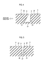
- Fig. 4 is an enlarged sectional view taken along the line A-A of Fig. 1 .
- an inside longitudinal wall 21 which defines the inside lateral groove Q of the inter-block lateral groove 7 tilts towards the rotation direction side of the tire as it goes from a road surface 22 to the inside in the tire radial direction.
- the inside lateral groove Q in its shape, tilts towards the rotation direction side of the tire as it goes from the tread surface 22 to the inside in the tire radial direction (in the downward direction of Figs. 3 and 4 ).
- the inside lateral groove is formed in a sectional trapezoidal shape of an inside longitudinal wall 21 which forms the tire circumferential end of the kicking out side 9; the inside longitudinal wall 23 which forms the tire circumferential end of the stepping side 8; and a bottom wall 24.
- the inside longitudinal wall 23 which forms the tire circumferential end of the stepping side 8 in the land block 5 is disposed substantially vertically from the tread surface 22 towards the inside in the tire radial direction.
- the cross section of the outside lateral groove P is formed in a sectional rectangle shape. Therefore, the outside longitudinal walls 25, 26 which form the tire circumferential ends of the stepping side 8 and the kicking-out side 9 in the land blocks 4, 5 are disposed substantially vertically from the tread surface 22 towards the inside in the tire radial direction, respectively.
- frictional wear energy is exemplified.
- heel and toe frictional wear there is a difference in frictional wear energy between a stepping side and a pick-out side in a land block, and it becomes problematic in a case where the frictional wear energy at the kicking-out side is greater than that at the stepping side.
- frictional wear energy is proportional to a product between a shear force and a slip.
- the Inventor of the present invention came up with the idea that components of a shear force mainly acting on heel and toe frictional wear are different from each other between the inside in the tire width direction and the outside in the tire width direction in land block.
- a main factor is a torsion when a land block is grounded or a shear force in the tire width direction increased by roll-up toward the inside in the width direction received from a tire side portion.
- a main factor becomes apparent that the shear force in the tire circumferential direction increased when a widthwise wall extending in the tire width direction, among the walls defining an outer circumference of a land block, falls backward relative to the tire rotation direction.
- the inside lateral groove angle ⁇ 1 relative to the tire circumferential direction of the inside lateral groove Q, among the inter-block lateral grooves 7 defining the widthwise walls of the land blocks 5, 6, is set to be smaller than the outside lateral groove angle ⁇ 2 relative to the tire circumferential direction of the outside lateral groove P, whereby shear deformation which may be one of the main factors for heel and toe frictional wear can be restrained irrespective of where the land blocks 5, 6 are positioned.
- Fig. 6 is a sectional view showing a cross section of an outside lateral groove according to the second embodiment
- Fig. 7 is a sectional view showing a cross section of an inside lateral groove according to the second embodiment.
- a longitudinal wall in its entirety, which forms a tire circumferential end of a kicking-out side 9 in a land block 4, tilts towards a rotation direction side of a tire as it goes from a tread surface 22 toward the inside in a tire radial direction.
- both of the inside longitudinal wall 21 that defines the inside lateral groove Q in the inter-block lateral groove 7 and the outside longitudinal wall 28 which defines the outside lateral groove P are allowed to tilt towards the rotation direction side of the tire as it goes from the tread surface 22 to the inside in the tire radial direction.
- the entire longitudinal wall that forms the tire circumferential end of the kicking-out side 9 in the land block 4 tilts toward the rotation direction side of the tire as it goes from the tread surface 22 towards the inside in the tire radial direction.
- the circumferential thin groove 10 was formed so as to link the inter-block lateral grooves 7, 7 that are adjacent to each other in the tire circumferential direction, this thin groove may be spaced from the inter-block lateral grooves 7, 7.
- one end of the widthwise thin groove 11 was opened, it may not be opened.
- a sipe may be formed in place of the circumferential thin groove 10 or the widthwise thin groove 11.
- Fig. 8 is a view showing a grounding surface 31 of a pneumatic air-containing tire according to the prior art
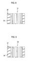
- Fig. 9 is a view showing a grounding surface 32 of a pneumatic air-containing tire according to Comparative Example
- Fig. 10 is a view showing a grounding surface 34 of a pneumatic air-containing tire according to Example of the present invention.
- a lateral groove 36 is formed in a land block 35 arranged at the left end part of the figure, this lateral groove 36 fails to satisfy the requirements of the angles ⁇ 1 and ⁇ 2 according to the present invention.
- an inside lateral groove angle ⁇ 1 is set to be greater than an outside lateral groove angle ⁇ 2; and therefore, this lateral groove fails to satisfy the requirements of the angle ⁇ 1 and ⁇ 2 according to the present invention.
- a tire size of a test tire is 225/45R17 90W
- a wheel size was set at 5JJ x 17 and an internal pressure was set at 220 kPa.
- the test tire was attached to a front shaft of an FR vehicle, the FR vehicle was allowed to run 10,000 km in field traveling, and thereafter, there was measured the amount of heel and toe frictional wear, which is a difference in height between a stepping side and a kicking-out side, as to two sites, that is, an inside end part and an outside end part in the tire width direction in a land block of a shoulder portion.
- the heel and toe frictional wear is indicated by a resistive heel and toe index while that of the prior art is defined to be 100.
- Table 1 The measurement results are shown in Table 1 below.
- the frictional wear energy at each site of a land block was measured.
- the measurement sites are as shown in Fig. 11 .
- the frictional wear energy at an E site was defined to be EW1
- the frictional wear energy at an F site was defined to be EW2
- a difference (EW2 - EW1) between a stepping side and a kicking-out side, of frictional wear energy was obtained.
- the frictional wear energy at a G site was defined to be EW3
- the frictional wear energy at an H site was defined to be EW4, and then, a difference (EW4 - EW3) between a stepping side and a kicking-out side, of the frictional wear energy, was obtained.
- EW2 - EW1 was 10 J/m 2
- EW4-EW3 was 15 J/m 2 .
- the tire according to the present invention there can be provided a tire of effectively restraining heel and toe frictional wear at both sides, at the outside in the tire width direction and at the inside in the tire width direction in a land block of a shoulder portion.
Landscapes
- Engineering & Computer Science (AREA)
- Mechanical Engineering (AREA)
- Tires In General (AREA)
Abstract
Description
- The present invention relates to a tire, and in further detail, to a tire which is capable of effectively restraining a heel and toe frictional wear at a shoulder portion, in particular.
- In general, in a vehicle tire, a plurality of circumferential grooves are provided to thereby ensure drainage property of rainwater or the like at the time of running a road surface, and lateral grooves which extend in a tire width direction are provided to thereby ensure high steering property. In addition, a plurality of land blocks are defined by these circumferential grooves and lateral grooves.
- In these land part blocks, at the time of tire rotation, one end part in a tire circumferential direction is present at a stepping side, and the other end part is present at a kicking-out side, the land blocks are deformed by being subjected to a resistive force from a road surface at the stepping-in site; and thereafter, a ground region moves from the stepping side to the kicking-out side and then is spaced from the road surface at an end part of the kicking-out side. Subsequently, the land blocks are restored to their original shape instantaneously when it is spaced from the road surface, and at the pick-out side, the road surface is frictionally worn while being subjected to a great grounding pressure; and therefore, there occurs a so called heel and toe frictional wear that, while a vehicle runs for a long period of time, the kicking-out side is frictionally worn more greatly than at the stepping side and a step difference arises at the land block.
- Here, in general, the heel and toe frictional wear significantly occurs at a site at the outside in a tire width direction of the land blocks at a shoulder portion; and therefore, conventionally, countermeasures against frictional wear of the site at the outside in the tire width direction have been mainly taken. As one of these countermeasures against frictional wear, there is a method of tilting a lateral groove angle in the tire width direction side relative to a tire circumferential direction and then restraining torsional deformation when the land blocks are grounded on a road surface. In addition, there is also known the art of forming a sipe which extends along the tire width direction in the land blocks and then lowering rigidity of the land blocks to thereby restrain the heel and toe frictional wear (for example, see Patent Document 1).
-
- Patent Document: Japanese Patent Application Laid-open No.
10-226207 Fig. 1 andFig. 2 ) - However, in the conventional tire described previously, while frictional wear relative to the outside in the tire width direction in the land blocks of the shoulder portion is improved, there has been apprehension that it becomes difficult to sufficiently improve the heal and toe frictional wear at the inside in the tire width direction.
- Therefore, the present invention has been made in view of such a circumstance, and an object of the present invention is to provide a tire which is capable of effectively restraining heel and toe frictional wears at both portions of the land blocks of the shoulder portion at the outside in the tire width direction and at the inside of the tire width direction. In order to solve the aforementioned problem, the present invention has the following features.
- Firstly, in a first feature of the present invention, a tire has a plurality of land blocks (
land blocks - As to the heel and toe frictional wear at a portion of the land block of the shoulder portion at the outside in the tire width direction, a main factor is a torsion when a land block is grounded or a shear force in the tire width direction increased by roll-up toward the inside in the width direction received from a tire side portion. As to the heel and toe frictional wear at a inside portion in the tire width direction, a main factor becomes apparent that the shear force in the tire circumferential direction increased when a widthwise wall extending in the tire width direction, among the walls defining an outer circumference of a land block, falls backward relative to the tire rotation direction.
- Therefore, the inside lateral groove angle θ1 relative to the tire circumferential direction of the inside lateral groove, among the lateral grooves defining the widthwise walls of the land blocks, is set to be smaller than the outside lateral groove angle θ2 relative to the tire circumferential direction of the outside lateral groove, whereby shear deformation which may be one of the main factors for heel and toe frictional wear can be restrained irrespective of where the land blocks are positioned.
- In the other features, the inside lateral groove angle θ1 is 30 degrees to 60 degrees and the outside lateral groove angle θ2 is 70 degrees to 90 degrees.
- In the other features, the inside lateral groove and the outside lateral groove are formed smoothly and continuously along the tire width direction.
- In the other features, a ratio Wx/W between a distance Wx and a total width W is 0.3 to 0.6, the distance Wx being a distance in the tire width direction from a tire width direction inside end of the land block to a cross point x where an extension line of the inside lateral groove crosses an extension line of the outside lateral groove, the total width W in the tire width direction of the land block.
- In the other features, an inside longitudinal wall defining the inside lateral groove of the inter-block lateral groove is included in a longitudinal wall forming a tire circumferential end at a kicking-out side in the land block, and the inside longitudinal wall tilts toward a rotation direction side of the tire, as the inside longitudinal wall becomes inside in a tire radial direction from a tread surface. In the other features, a longitudinal wall forming a tire circumferential end at a kicking-out side in the land block entirely tilts toward a rotation direction side of the tire, as the inside longitudinal wall becomes inside in a tire radial direction from a tread surface.
- In the other features, a circumferential thin groove extending in the tire circumferential direction is formed at an inside portion of the land block in the tire width direction.
- In the other features, a widthwise thin groove extending in the tire width direction is formed at an outside portion of the land block in the tire width direction.
- In the other features, the inter-block lateral groove is formed at the shoulder portion.
- In the other features, an angle θ3 formed by the extension line of the inside lateral groove and the extension line of the outside lateral groove is an obtuse angle.
- According to the present invention, provide is a tire which is capable of effectively restraining heel and toe frictional wears at both portions of the land blocks of the shoulder portion at the outside in the tire width direction and at the inside of the tire width direction.
-
- [
Fig. 1] Fig. 1 is an exploded view showing a tread pattern of a pneumatic air-containing tire according to a first embodiment of the present invention. - [
Fig. 2] Fig. 2 is an enlarged exploded view of essential parts ofFig. 1 . - [
Fig. 3] Fig. 3 is a perspective view virtually showing an inter-block lateral groove according to the first embodiment of the present invention. - [
Fig. 4] Fig. 4 is an enlarged sectional view taken along the line A-A ofFig. 1 . - [
Fig. 5] Fig. 5 is an enlarged sectional view taken along the line B-B ofFig. 1 . - [
Fig. 6] Fig. 6 is a sectional view showing a cross section of an outside lateral groove according to a second embodiment of the present invention. - [
Fig. 7] Fig. 7 is a sectional view showing a cross section of an inside lateral groove according to the second embodiment of the present invention. - [
Fig. 8] Fig. 8 is a view showing a grounding surface of a pneumatic air-containing tire according to the prior art. - [
Fig. 9] Fig. 9 is a view showing a grounding surface of a pneumatic air-containing tire according to Comparative Example. - [
Fig. 10] Fig. 10 is a view showing a grounding surface of a pneumatic air-containing tire according to Example of the present invention. - [
Fig. 11] Fig. 11 is a view showing a grounding surface of a pneumatic air-containing tire showing a measurement site of frictional wear energy in the pneumatic air-containing air of the Example. - Next, an embodiment of a pneumatic air-containing tire according to the present invention will be described with reference to the drawings. In the following description of the drawings, the same or like constituent elements are designated by the same or like reference numerals. However, it should be kept in mind that the drawings are merely provided as schematic ones, and that each of the ratios of dimensions or the like is different from actual ones.
- Therefore, specific dimensions or the like should be determined in consideration of the following description. In addition, it is a matter of course that, among the drawings as well, portions of which interrelationships of dimensions or ratios are different from each other are included.
- First, a first embodiment according to the present invention will be described.
-
Fig. 1 is an exploded view showing a tread pattern 1 of a pneumatic air-containing tire according to a first embodiment of the present invention, wherein a rotation direction of the tire is indicated by the arrow. This tread pattern 1 is formed laterally symmetrically relative to a tire widthwise center (tire equator line) CL of a tread portion. In addition,Fig. 2 is an enlarged exploded view of essential parts ofFig. 1 . - As shown in
Fig. 1 , at the tread portion, a plurality ofcircumferential grooves 2, 3 (three in the embodiment) are formed along a tire circumferential direction. Thesecircumferential grooves 2, 3 are made of a centralcircumferential groove 2 which is disposed at a center in the tire width direction, and outside circumferential grooves 3, 3 which are disposed at both sides in the tire width direction. At the outside in the tire width direction of this outside circumferential groove 3,land blocks land blocks land block 4 and anadjacent land block 5 which is adjacent in the tire circumferential direction relative to thepredetermined land block 4, an inter-blocklateral groove 7 which extends in the tire width direction is formed. That is, the inter-blocklateral groove 7 is formed only at the shoulder portion. Among the tire circumferential end parts of the land block, an end part at the rotation direction side of the tire serves as a so calledstepping side 8 and an opposite end part to the rotation direction of the tire serves as a so called kicking-outside 9. - In addition, a circumferential
thin groove 10 which extends in the tire circumferential direction is provided at a site at the inside in the tire width direction in theland block 5. The circumferentialthin grooves 10, in the embodiment, cause the adjacent inter-blocklateral grooves thin grooves 11 which extends in the tire width direction is formed at a site at the outside in the tire width direction in theland block 5, and an end part at the outside of a vehicle in the widthwisethin groove 11 opens. - As shown in
Fig. 2 , the inter-blocklateral groove 7 is formed to be bent in an inverted V-letter shape in a plan view on a boundary of abent portion 12 which is disposed intermediate portion in the tire width direction. The outside of thebent portion 12 in the tire width direction is an outside lateral groove P, and the inside of thebent portion 12 in the tire width direction is an inside lateral groove Q. - An inside lateral groove angle, which is an angle formed between an extension direction of the inside lateral groove Q and a tire circumferential direction, is set at θ1, and the outside lateral groove angle, which is an angle formed between an extension direction of the outside lateral groove P and the tire circumferential direction, is set at θ2 This angle θ1 is set at a value which is smaller than the angle θ2. Specifically, the inside lateral groove angle θ1 is 30 degrees to 60 degrees, and the outside lateral groove angle θ2 is 70 degrees to 90 degrees. Further, it is preferable that the inside lateral groove angle θ1 is 40 degrees to 50 degrees, and it is preferable that the outside lateral groove angle θ2 is 80 degrees to 90 degrees.
- The inside lateral groove Q and the outside lateral groove P are formed smoothly and continuously along the tire width direction. An angle θ3, which is formed by an extension line of the inside lateral groove Q and an extension line of the outside lateral groove P, is an obtuse angle.
- Further, as is evident from
Fig. 2 , a distance in the tire width direction from a tire widthwiseinside end 13 of a land block 6 to a cross point x where the extension line of the inside lateral groove Q crosses the extension line of the outside lateral groove P is set at Wx. On the other hand, a total width in the tire width direction of the land block 6 is set at W, and a ratio Wx/W relative to W of Wx is set at 0.3 to 0.6. It is further preferable that this ratio Wx/W is 0.4 to 0.6. -
Fig. 3 is a perspective view virtually showing an inter-block lateral groove according to the first embodiment of the present invention, andFig. 4 is an enlarged sectional view taken along the line A-A ofFig. 1 . - Among longitudinal walls which form a tire circumferential end of the kicking-out
side 9 in theland block 4, an insidelongitudinal wall 21 which defines the inside lateral groove Q of the inter-blocklateral groove 7 tilts towards the rotation direction side of the tire as it goes from aroad surface 22 to the inside in the tire radial direction. - That is, as shown in
Fig. 3 andFig. 4 , the inside lateral groove Q, in its shape, tilts towards the rotation direction side of the tire as it goes from thetread surface 22 to the inside in the tire radial direction (in the downward direction ofFigs. 3 and4 ). In this manner, the inside lateral groove is formed in a sectional trapezoidal shape of an insidelongitudinal wall 21 which forms the tire circumferential end of the kicking outside 9; the insidelongitudinal wall 23 which forms the tire circumferential end of the steppingside 8; and abottom wall 24. However, the insidelongitudinal wall 23 which forms the tire circumferential end of the steppingside 8 in theland block 5 is disposed substantially vertically from thetread surface 22 towards the inside in the tire radial direction. - As shown in
Fig. 5 , among the inter-blocklateral grooves 7, the cross section of the outside lateral groove P is formed in a sectional rectangle shape. Therefore, the outsidelongitudinal walls side 8 and the kicking-outside 9 in the land blocks 4, 5 are disposed substantially vertically from thetread surface 22 towards the inside in the tire radial direction, respectively. -
- (1) A inter-block
lateral groove 7, which is disposed between apredetermined land block 5 and an adjacent land block 6 which is adjacent to theland block 5 at the tire circumferential direction side of theland block 5, are comprised of an inside lateral groove Q which is disposed at the inside in the tire width direction on a boundary of abent portion 12 which is formed intermediate portion in the tire width direction; and an outside lateral groove P which is disposed at the outside in the tire width direction, and an inside lateral groove angle θ1 relative to the tire circumferential direction of the inside lateral groove Q is set to be smaller than an outside lateral groove angle θ2 relative to the tire circumferential direction of the outside lateral groove P. - In general, as one of indexes showing easiness of frictional wear, frictional wear energy is exemplified. In heel and toe frictional wear, there is a difference in frictional wear energy between a stepping side and a pick-out side in a land block, and it becomes problematic in a case where the frictional wear energy at the kicking-out side is greater than that at the stepping side. Here, it is generally known that frictional wear energy is proportional to a product between a shear force and a slip. Then, at this time, the Inventor of the present invention came up with the idea that components of a shear force mainly acting on heel and toe frictional wear are different from each other between the inside in the tire width direction and the outside in the tire width direction in land block.
- That is, as to the heel and toe frictional wear at a portion of the land block of the shoulder portion at the outside in the tire width direction, a main factor is a torsion when a land block is grounded or a shear force in the tire width direction increased by roll-up toward the inside in the width direction received from a tire side portion. As to the heel and toe frictional wear at a inside portion in the tire width direction, a main factor becomes apparent that the shear force in the tire circumferential direction increased when a widthwise wall extending in the tire width direction, among the walls defining an outer circumference of a land block, falls backward relative to the tire rotation direction.
- Therefore, the inside lateral groove angle θ1 relative to the tire circumferential direction of the inside lateral groove Q, among the inter-block
lateral grooves 7 defining the widthwise walls of the land blocks 5, 6, is set to be smaller than the outside lateral groove angle θ2 relative to the tire circumferential direction of the outside lateral groove P, whereby shear deformation which may be one of the main factors for heel and toe frictional wear can be restrained irrespective of where the land blocks 5, 6 are positioned. -
- (2) The inside lateral groove angle θ1 is 30 degrees to 60 degrees, and it is preferable to set the outside lateral groove angle θ2 at 70 degrees to 90 degrees. By setting the inside lateral groove angle θ1 at 30 degrees to 60 degrees, it is possible to restrain the widthwise wall at the inside in the tire width direction of the
land block 5 from falling backward relative to the tire rotation direction. On the other hand, by setting the outside lateral groove angle θ2 at 70 degrees to 90 degrees, it is possible to suitably restrain a torsion at the time of grounding at the outside in the tire width direction in theland block 5. -
- (3) The inside lateral groove Q and the outside lateral groove P are formed smoothly continuously along the tire width direction. Thus, when the land blocks 5, 6 are grounded, deformation never occurs in a one-sided manner at a specific one part of the inter-block
lateral groove 7, and an occurrence of abnormal frictional wear can be prevented. -
- (4) A ratio Wx/W between: a distance Wx taken along the tire width direction from a cross point x between the extension line of the inside lateral groove W and the extension line of the outside lateral groove P up to a tire widthwise
inside end 13 of the land block 6; and a total width W taken along the tire width direction of the land block 6 is set at 0.3 to 0.6. Therefore, the land blocks 5, 6 can be set so as not to be too elongated in the tire circumferential direction while the widthwise wall at the inside in the tire width direction of theland block 5 is restrained from falling backward relative to the tire rotation direction, and when theland block 5 is grounded, a torsion at a site at the outside in the tire width direction can be effectively prevented. -
- (5) Among the longitudinal walls which form a tire circumferential end of the kicking-out
side 9 in theland block 4, the insidelongitudinal wall 21 which defines the inside lateral groove Q of the inter-blocklateral groove 7 tilts towards the tire rotation direction side as it goes from thetread surface 22 toward the inside in the tire radial direction. Therefore, since an end part of the kicking-outside 9 in theland block 4 is lower in rigidity than that of the steppingside 8, the frictional wear energy at the kicking-outside 9 is reduced and then heel and toe frictional wear is mitigated. -
- (6) A circumferential
thin groove 10 which extends in the tire circumferential direction is provided at a site at the inside in the tire width direction in theland block 5. Thus, there is an advantageous effect of alleviating deformation of theland block 5, increasing in the tire circumferential direction. -
- (7) A circumferential
thin groove 11 which extends in the tire width direction is provided at a site at the outside in the tire width direction in theland block 5. Therefore, there is an advantageous effect of alleviating deformation of theland block 5, increasing in the tire circumferential direction. -
- (8) Frictional wear which may be one of the main causes of an inter-block
lateral groove 7 is formed only at a shoulder portion. Thus, the heel and toe frictional wear at a site at the outside in the tire width direction in theland block 5 of the shoulder portion, that is, a torsion exerted when a land block is grounded or a shear force in the tire width direction in which a tread surface after grounded increases roll-up at the inside in the width direction received from a tire side portion can be effectively restrained. -
- (9) An angle θ3, which is formed by the extension line of an inside lateral groove and an extension line of the outside lateral groove is an obtuse angle. Therefore, a shear deformation which may be one of the main causes of heel and toe frictional wear can be further restrained without lowering rigidity of the
land block 5. - Next, a second embodiment according to the present invention will be described.
-
Fig. 6 is a sectional view showing a cross section of an outside lateral groove according to the second embodiment, andFig. 7 is a sectional view showing a cross section of an inside lateral groove according to the second embodiment. - In the embodiment, a longitudinal wall, in its entirety, which forms a tire circumferential end of a kicking-out
side 9 in aland block 4, tilts towards a rotation direction side of a tire as it goes from atread surface 22 toward the inside in a tire radial direction. - That is, in the first embodiment described previously, among the longitudinal walls which form the tire circumferential end of the kicking-out
side 9 in theland block 4, only an insidelongitudinal wall 21 which defines the inside lateral groove Q in the inter-blocklateral groove 7 was allowed to tilt towards the rotation direction side of the tire as it goes from thetread surface 22 toward the inside in the tire radial direction. On the other hand, in the embodiment, both of the insidelongitudinal wall 21 that defines the inside lateral groove Q in the inter-blocklateral groove 7 and the outsidelongitudinal wall 28 which defines the outside lateral groove P are allowed to tilt towards the rotation direction side of the tire as it goes from thetread surface 22 to the inside in the tire radial direction. - The entire longitudinal wall that forms the tire circumferential end of the kicking-out
side 9 in theland block 4 tilts toward the rotation direction side of the tire as it goes from thetread surface 22 towards the inside in the tire radial direction. - Therefore, there is an advantageous effect that swelling out of the
land block 4 is restrained and a shear force in the tire circumferential direction is reduced. - As described previously, while the contents of the present invention were disclosed through the embodiments of the present invention, it should not be understood that the discussion and drawings which form a part of this disclosure limit the present invention. From this disclosure, a variety of alternative embodiments, examples, and operational techniques would become self-evident to one skilled in the art.
- For example, while, in the embodiments, the circumferential
thin groove 10 was formed so as to link the inter-blocklateral grooves lateral grooves thin groove 11 was opened, it may not be opened. Further, a sipe may be formed in place of the circumferentialthin groove 10 or the widthwisethin groove 11. - In this way, it is a matter of course that the present invention is inclusive of a variety of embodiments or the like which are not described herein. Therefore, a technical scope of the present invention is defined only by specific matters of the invention according to the claims that are reasonable from the foregoing description.
- Next, a description will be furbished as to results of tests which were performed with use of a pneumatic air-containing tire according to the prior art, Comparative Example, and Example of the present invention.
-
Fig. 8 is a view showing agrounding surface 31 of a pneumatic air-containing tire according to the prior art;Fig. 9 is a view showing agrounding surface 32 of a pneumatic air-containing tire according to Comparative Example; andFig. 10 is a view showing agrounding surface 34 of a pneumatic air-containing tire according to Example of the present invention. - While, in the
grounding surface 31 of the pneumatic air-containing tire shown as the prior art, alateral groove 36 is formed in aland block 35 arranged at the left end part of the figure, thislateral groove 36 fails to satisfy the requirements of the angles θ1 and θ2 according to the present invention. - While, in the
grounding surface 32 of the pneumatic air-containing tire shown as Comparative Example, as to alateral groove 38 disposed between the land blocks 37, an inside lateral groove angle θ1 is set to be greater than an outside lateral groove angle θ2; and therefore, this lateral groove fails to satisfy the requirements of the angle θ1 and θ2 according to the present invention. - A tire size of a test tire is 225/45R17 90W A wheel size was set at 5JJ x 17 and an internal pressure was set at 220 kPa. The test tire was attached to a front shaft of an FR vehicle, the FR vehicle was allowed to run 10,000 km in field traveling, and thereafter, there was measured the amount of heel and toe frictional wear, which is a difference in height between a stepping side and a kicking-out side, as to two sites, that is, an inside end part and an outside end part in the tire width direction in a land block of a shoulder portion. The heel and toe frictional wear is indicated by a resistive heel and toe index while that of the prior art is defined to be 100. The measurement results are shown in Table 1 below. It is indicated that the smaller the resistive heel and toe index is, the better it is. In addition, an inside lateral groove angle θ1 relative to the tire circumferential direction of an inside lateral groove, an outside lateral groove angle θ2 relative to the tire circumferential direction of an outside lateral groove, and a ratio Wx/W of a width Wx of an inside lateral groove between land blocks were computed.
[Table 1] Prior Art Comparative Example Example Index Inside in width direction 100 100 70 Outside in width direction 100 160 90 θ1 70° 80° 45° θ2 85° 45° 80° Wx/W 0.35 0.35 0.35 - As a result, it was found that the amount of heel and toe frictional wear is reduced by about 30% remarkably than that of the prior art at an end part of the inside in the tire width direction and is reduced at 10% more remarkably than that of the prior art at an outside end part in the tire width direction.
- Next, the frictional wear energy at each site of a land block was measured. The measurement sites are as shown in
Fig. 11 . As to an inside end part in the tire width direction in aland block 41, the frictional wear energy at an E site was defined to be EW1, the frictional wear energy at an F site was defined to be EW2, and then, a difference (EW2 - EW1) between a stepping side and a kicking-out side, of frictional wear energy, was obtained. In addition, as to an outside end part in the tire width direction, the frictional wear energy at a G site was defined to be EW3, the frictional wear energy at an H site was defined to be EW4, and then, a difference (EW4 - EW3) between a stepping side and a kicking-out side, of the frictional wear energy, was obtained. As a result, EW2 - EW1 was 10 J/m2, and EW4-EW3 was 15 J/m2. These values are represented by indexes while a reference of the prior art was defined to be 100, and it is meant that the smaller the values of the indexes are, the higher the resistive heel and toe frictional wear property is. - In this manner, according to the present invention, it was found that the heel and toe frictional wear at both of an inside end part and an outside end part in the tire width direction of a land block can be effectively restrained.
- The entire contents of Japanese Patent Application No.
2008-271133 - As described hereinbefore, as the tire according to the present invention, there can be provided a tire of effectively restraining heel and toe frictional wear at both sides, at the outside in the tire width direction and at the inside in the tire width direction in a land block of a shoulder portion.
Claims (10)
- A tire in which a plurality of land blocks are formed by a circumferential groove which extends in a tire circumferential direction and a lateral groove which extends in a tire width direction, and formed on at least one of a tread potion and a shoulder portion, wherein
an inter-block lateral groove is disposed between a predetermined land block and an adjacent land block which is adjacent to the predetermined land block at a tire circumferential direction side of the predetermined land block, among the plurality of the land blocks, and is formed of an inside lateral groove and an outside lateral groove, the inside lateral groove being disposed at an inside of a boundary of a bent portion in a tire width direction, the outside lateral groove being disposed at an outside of the bent portion, the bent portion being formed at intermediate portion in the tire width direction, and
an inside lateral groove angle θ1 relative to the tire circumferential direction of the inside lateral groove is smaller than an outside lateral groove angle θ2 relative to the tire circumferential direction of the outside lateral groove. - The tire according to claim 1, wherein
the inside lateral groove angle θ1 is 30 degrees to 60 degrees and the outside lateral groove angle θ2 is 70 degrees to 90 degrees. - The tire according to claim 1 or claim 2, wherein
the inside lateral groove and the outside lateral groove are formed smoothly and continuously along the tire width direction. - The tire according to any one of claims 1 to 3, wherein
a ratio Wx/W between a distance Wx and a total width W is 0.3 to 0.6, the distance Wx being a distance in the tire width direction from a tire width direction inside end of the land block to a cross point x where an extension line of the inside lateral groove crosses an extension line of the outside lateral groove, the total width W in the tire width direction of the land block. - The tire according to any one of claims 1 to 4, wherein
an inside longitudinal wall defining the inside lateral groove of the inter-block lateral groove is included in a longitudinal wall forming a tire circumferential end at a kicking-out side in the land block, and the inside longitudinal wall tilts toward a rotation direction side of the tire, as the inside longitudinal wall becomes inside in a tire radial direction from a tread surface. - The tire according to any one of claims 1 to 4, wherein
a longitudinal wall forming a tire circumferential end at a kicking-out side in the land block entirely tilts toward a rotation direction side of the tire, as the inside longitudinal wall becomes inside in a tire radial direction from a tread surface. - The tire according to any one of claims 1 to 6, wherein
a circumferential thin groove extending in the tire circumferential direction is formed at an inside portion of the land block in the tire width direction. - The tire according to any one of claims 1 to 7, wherein
a widthwise thin groove extending in the tire width direction is formed at an outside portion of the land block in the tire width direction. - The tire according to any one of claims 1 to 8, wherein
the inter-block lateral groove is formed at the shoulder portion. - The tire according to any one of claims 1 to 9, wherein
an angle θ3 formed by the extension line of the inside lateral groove and the extension line of the outside lateral groove is an obtuse angle.
Applications Claiming Priority (2)
| Application Number | Priority Date | Filing Date | Title |
|---|---|---|---|
| JP2008271133 | 2008-10-21 | ||
| PCT/JP2009/068142 WO2010047353A1 (en) | 2008-10-21 | 2009-10-21 | Tire |
Publications (3)
| Publication Number | Publication Date |
|---|---|
| EP2347918A1 true EP2347918A1 (en) | 2011-07-27 |
| EP2347918A4 EP2347918A4 (en) | 2012-09-19 |
| EP2347918B1 EP2347918B1 (en) | 2015-05-27 |
Family
ID=42119390
Family Applications (1)
| Application Number | Title | Priority Date | Filing Date |
|---|---|---|---|
| EP09822050.2A Not-in-force EP2347918B1 (en) | 2008-10-21 | 2009-10-21 | Tire |
Country Status (6)
| Country | Link |
|---|---|
| US (1) | US8820374B2 (en) |
| EP (1) | EP2347918B1 (en) |
| JP (1) | JPWO2010047353A1 (en) |
| KR (1) | KR20110084425A (en) |
| CN (1) | CN102196926A (en) |
| WO (1) | WO2010047353A1 (en) |
Families Citing this family (3)
| Publication number | Priority date | Publication date | Assignee | Title |
|---|---|---|---|---|
| JP6467792B2 (en) * | 2014-06-23 | 2019-02-13 | 横浜ゴム株式会社 | Tire wear prediction method |
| JP6467793B2 (en) * | 2014-06-30 | 2019-02-13 | 横浜ゴム株式会社 | Tire wear prediction method |
| JP7284693B2 (en) * | 2019-12-05 | 2023-05-31 | 株式会社ブリヂストン | pneumatic tire |
Family Cites Families (23)
| Publication number | Priority date | Publication date | Assignee | Title |
|---|---|---|---|---|
| JPS62157810A (en) * | 1985-12-30 | 1987-07-13 | Yokohama Rubber Co Ltd:The | Pneumatic tire |
| US4690189A (en) * | 1986-01-29 | 1987-09-01 | The Goodyear Tire & Rubber Company | All-season pneumatic tire with chamfered tread blocks |
| JPS62255203A (en) * | 1986-04-30 | 1987-11-07 | Bridgestone Corp | Pneumatic radial tire |
| JPS63141804A (en) * | 1986-12-05 | 1988-06-14 | Yokohama Rubber Co Ltd:The | Pneumatic tire |
| JPS63188505A (en) * | 1987-01-29 | 1988-08-04 | Yokohama Rubber Co Ltd:The | Low noise pneumatic tire |
| JPH07115570B2 (en) * | 1987-03-11 | 1995-12-13 | 株式会社ブリヂストン | Pneumatic tire |
| JPH0338412A (en) * | 1989-07-05 | 1991-02-19 | Bridgestone Corp | Eccentric wear controlled pneumatic tire |
| JP3682658B2 (en) * | 1993-07-20 | 2005-08-10 | Necトーキン株式会社 | Magnetic heating element and magnetic material used therefor |
| US5960845A (en) | 1993-07-23 | 1999-10-05 | Sumitomo Rubber Industries, Ltd. | Pneumatic tire |
| JP3400134B2 (en) | 1994-09-20 | 2003-04-28 | 株式会社ブリヂストン | Pneumatic radial tire |
| JP3542687B2 (en) | 1996-06-11 | 2004-07-14 | 株式会社ブリヂストン | Pneumatic tire |
| JP3784907B2 (en) | 1997-02-17 | 2006-06-14 | 株式会社ブリヂストン | Pneumatic tire |
| JP3954180B2 (en) * | 1997-12-19 | 2007-08-08 | 株式会社ブリヂストン | Pneumatic tire |
| JP4111474B2 (en) * | 1998-09-21 | 2008-07-02 | 東洋ゴム工業株式会社 | Pneumatic radial tire |
| FR2800675A1 (en) | 1999-11-08 | 2001-05-11 | Michelin Soc Tech | PATTERN OF SCULPTING A TREAD |
| ES2248152T3 (en) | 1999-12-01 | 2006-03-16 | Pirelli Pneumatici Societa Per Azioni | TIRE FOR VEHICLE WHEELS. |
| IT1314248B1 (en) | 1999-12-01 | 2002-12-06 | Pirelli | Vehicle wheel tire for use on wet roads, has transversal notch extending beyond longitudinal median plane of central rows of tread band |
| JP4369702B2 (en) * | 2003-07-29 | 2009-11-25 | パナソニック株式会社 | Switching power supply |
| JP4927312B2 (en) * | 2003-11-28 | 2012-05-09 | 株式会社ブリヂストン | Pneumatic tire |
| JP4569277B2 (en) * | 2004-11-29 | 2010-10-27 | 横浜ゴム株式会社 | Pneumatic tire |
| JP4392339B2 (en) | 2004-12-24 | 2009-12-24 | 住友ゴム工業株式会社 | Pneumatic tire |
| JP4818189B2 (en) | 2007-04-19 | 2011-11-16 | キヤノン株式会社 | Imaging apparatus and control method thereof |
| ATE512006T1 (en) * | 2007-11-05 | 2011-06-15 | Pirelli | TIRE |
-
2009
- 2009-10-21 KR KR1020117011597A patent/KR20110084425A/en not_active Ceased
- 2009-10-21 CN CN2009801419819A patent/CN102196926A/en active Pending
- 2009-10-21 JP JP2010534833A patent/JPWO2010047353A1/en active Pending
- 2009-10-21 EP EP09822050.2A patent/EP2347918B1/en not_active Not-in-force
- 2009-10-21 US US13/125,215 patent/US8820374B2/en active Active
- 2009-10-21 WO PCT/JP2009/068142 patent/WO2010047353A1/en not_active Ceased
Also Published As
| Publication number | Publication date |
|---|---|
| JPWO2010047353A1 (en) | 2012-03-22 |
| EP2347918A4 (en) | 2012-09-19 |
| KR20110084425A (en) | 2011-07-22 |
| WO2010047353A1 (en) | 2010-04-29 |
| US20110247739A1 (en) | 2011-10-13 |
| CN102196926A (en) | 2011-09-21 |
| EP2347918B1 (en) | 2015-05-27 |
| US8820374B2 (en) | 2014-09-02 |
Similar Documents
| Publication | Publication Date | Title |
|---|---|---|
| EP3205516B1 (en) | Pneumatic tire | |
| KR101793632B1 (en) | Pneumatic tire | |
| US8813800B2 (en) | Pneumatic tire | |
| US6116309A (en) | Tread for a tire including five rib parts | |
| US4230512A (en) | Center block side rib tread pattern for heavy vehicle radial tires | |
| EP2452836B1 (en) | Heavy duty pneumatic tire | |
| EP3040216B1 (en) | Pneumatic tire | |
| EP2724873B1 (en) | Tire | |
| KR101740739B1 (en) | Pneumatic tire | |
| EP2308695A1 (en) | Pneumatic tire | |
| EP3375633B1 (en) | Tire | |
| EP3450209B1 (en) | Pneumatic radial tire | |
| US9469159B2 (en) | Pneumatic tire | |
| US20190160879A1 (en) | Tire | |
| CN103818193A (en) | Pneumatic tire | |
| EP2602127B1 (en) | Tire | |
| EP1946941B1 (en) | Pneumatic tire | |
| RU2717113C2 (en) | Tire tread for agricultural vehicle | |
| EP2347918B1 (en) | Tire | |
| EP3828011B1 (en) | Tyre tread | |
| EP3611037B1 (en) | Tyre for running on rough terrain | |
| JPH02169305A (en) | Heavy load pneumatic tire wherefrom biased wear is prevented | |
| US11135877B2 (en) | Tire | |
| JP4936520B2 (en) | Pneumatic radial tire | |
| JPH106716A (en) | Pneumatic tires for heavy loads that prevent uneven wear |
Legal Events
| Date | Code | Title | Description |
|---|---|---|---|
| PUAI | Public reference made under article 153(3) epc to a published international application that has entered the european phase |
Free format text: ORIGINAL CODE: 0009012 |
|
| 17P | Request for examination filed |
Effective date: 20110506 |
|
| AK | Designated contracting states |
Kind code of ref document: A1 Designated state(s): AT BE BG CH CY CZ DE DK EE ES FI FR GB GR HR HU IE IS IT LI LT LU LV MC MK MT NL NO PL PT RO SE SI SK SM TR |
|
| AX | Request for extension of the european patent |
Extension state: AL BA RS |
|
| DAX | Request for extension of the european patent (deleted) | ||
| RIN1 | Information on inventor provided before grant (corrected) |
Inventor name: TOMIDA, TATSUYA |
|
| RIN1 | Information on inventor provided before grant (corrected) |
Inventor name: TOMIDA, TATSUYA |
|
| A4 | Supplementary search report drawn up and despatched |
Effective date: 20120822 |
|
| RIC1 | Information provided on ipc code assigned before grant |
Ipc: B60C 11/11 20060101AFI20120816BHEP Ipc: B60C 11/13 20060101ALI20120816BHEP Ipc: B60C 11/04 20060101ALI20120816BHEP Ipc: B60C 11/01 20060101ALI20120816BHEP |
|
| 17Q | First examination report despatched |
Effective date: 20140304 |
|
| GRAP | Despatch of communication of intention to grant a patent |
Free format text: ORIGINAL CODE: EPIDOSNIGR1 |
|
| INTG | Intention to grant announced |
Effective date: 20141121 |
|
| GRAS | Grant fee paid |
Free format text: ORIGINAL CODE: EPIDOSNIGR3 |
|
| GRAA | (expected) grant |
Free format text: ORIGINAL CODE: 0009210 |
|
| AK | Designated contracting states |
Kind code of ref document: B1 Designated state(s): AT BE BG CH CY CZ DE DK EE ES FI FR GB GR HR HU IE IS IT LI LT LU LV MC MK MT NL NO PL PT RO SE SI SK SM TR |
|
| REG | Reference to a national code |
Ref country code: GB Ref legal event code: FG4D |
|
| REG | Reference to a national code |
Ref country code: CH Ref legal event code: EP |
|
| REG | Reference to a national code |
Ref country code: AT Ref legal event code: REF Ref document number: 728629 Country of ref document: AT Kind code of ref document: T Effective date: 20150615 |
|
| REG | Reference to a national code |
Ref country code: IE Ref legal event code: FG4D |
|
| REG | Reference to a national code |
Ref country code: DE Ref legal event code: R096 Ref document number: 602009031487 Country of ref document: DE |
|
| REG | Reference to a national code |
Ref country code: AT Ref legal event code: MK05 Ref document number: 728629 Country of ref document: AT Kind code of ref document: T Effective date: 20150527 |
|
| REG | Reference to a national code |
Ref country code: LT Ref legal event code: MG4D |
|
| PG25 | Lapsed in a contracting state [announced via postgrant information from national office to epo] |
Ref country code: ES Free format text: LAPSE BECAUSE OF FAILURE TO SUBMIT A TRANSLATION OF THE DESCRIPTION OR TO PAY THE FEE WITHIN THE PRESCRIBED TIME-LIMIT Effective date: 20150527 Ref country code: HR Free format text: LAPSE BECAUSE OF FAILURE TO SUBMIT A TRANSLATION OF THE DESCRIPTION OR TO PAY THE FEE WITHIN THE PRESCRIBED TIME-LIMIT Effective date: 20150527 Ref country code: FI Free format text: LAPSE BECAUSE OF FAILURE TO SUBMIT A TRANSLATION OF THE DESCRIPTION OR TO PAY THE FEE WITHIN THE PRESCRIBED TIME-LIMIT Effective date: 20150527 Ref country code: LT Free format text: LAPSE BECAUSE OF FAILURE TO SUBMIT A TRANSLATION OF THE DESCRIPTION OR TO PAY THE FEE WITHIN THE PRESCRIBED TIME-LIMIT Effective date: 20150527 Ref country code: PT Free format text: LAPSE BECAUSE OF FAILURE TO SUBMIT A TRANSLATION OF THE DESCRIPTION OR TO PAY THE FEE WITHIN THE PRESCRIBED TIME-LIMIT Effective date: 20150928 Ref country code: NO Free format text: LAPSE BECAUSE OF FAILURE TO SUBMIT A TRANSLATION OF THE DESCRIPTION OR TO PAY THE FEE WITHIN THE PRESCRIBED TIME-LIMIT Effective date: 20150827 |
|
| REG | Reference to a national code |
Ref country code: NL Ref legal event code: MP Effective date: 20150527 |
|
| PG25 | Lapsed in a contracting state [announced via postgrant information from national office to epo] |
Ref country code: BG Free format text: LAPSE BECAUSE OF FAILURE TO SUBMIT A TRANSLATION OF THE DESCRIPTION OR TO PAY THE FEE WITHIN THE PRESCRIBED TIME-LIMIT Effective date: 20150827 Ref country code: GR Free format text: LAPSE BECAUSE OF FAILURE TO SUBMIT A TRANSLATION OF THE DESCRIPTION OR TO PAY THE FEE WITHIN THE PRESCRIBED TIME-LIMIT Effective date: 20150828 Ref country code: AT Free format text: LAPSE BECAUSE OF FAILURE TO SUBMIT A TRANSLATION OF THE DESCRIPTION OR TO PAY THE FEE WITHIN THE PRESCRIBED TIME-LIMIT Effective date: 20150527 Ref country code: IS Free format text: LAPSE BECAUSE OF FAILURE TO SUBMIT A TRANSLATION OF THE DESCRIPTION OR TO PAY THE FEE WITHIN THE PRESCRIBED TIME-LIMIT Effective date: 20150927 Ref country code: LV Free format text: LAPSE BECAUSE OF FAILURE TO SUBMIT A TRANSLATION OF THE DESCRIPTION OR TO PAY THE FEE WITHIN THE PRESCRIBED TIME-LIMIT Effective date: 20150527 |
|
| PG25 | Lapsed in a contracting state [announced via postgrant information from national office to epo] |
Ref country code: EE Free format text: LAPSE BECAUSE OF FAILURE TO SUBMIT A TRANSLATION OF THE DESCRIPTION OR TO PAY THE FEE WITHIN THE PRESCRIBED TIME-LIMIT Effective date: 20150527 Ref country code: DK Free format text: LAPSE BECAUSE OF FAILURE TO SUBMIT A TRANSLATION OF THE DESCRIPTION OR TO PAY THE FEE WITHIN THE PRESCRIBED TIME-LIMIT Effective date: 20150527 |
|
| PG25 | Lapsed in a contracting state [announced via postgrant information from national office to epo] |
Ref country code: PL Free format text: LAPSE BECAUSE OF FAILURE TO SUBMIT A TRANSLATION OF THE DESCRIPTION OR TO PAY THE FEE WITHIN THE PRESCRIBED TIME-LIMIT Effective date: 20150527 Ref country code: RO Free format text: LAPSE BECAUSE OF NON-PAYMENT OF DUE FEES Effective date: 20150527 Ref country code: CZ Free format text: LAPSE BECAUSE OF FAILURE TO SUBMIT A TRANSLATION OF THE DESCRIPTION OR TO PAY THE FEE WITHIN THE PRESCRIBED TIME-LIMIT Effective date: 20150527 Ref country code: SK Free format text: LAPSE BECAUSE OF FAILURE TO SUBMIT A TRANSLATION OF THE DESCRIPTION OR TO PAY THE FEE WITHIN THE PRESCRIBED TIME-LIMIT Effective date: 20150527 |
|
| REG | Reference to a national code |
Ref country code: DE Ref legal event code: R097 Ref document number: 602009031487 Country of ref document: DE |
|
| PLBE | No opposition filed within time limit |
Free format text: ORIGINAL CODE: 0009261 |
|
| STAA | Information on the status of an ep patent application or granted ep patent |
Free format text: STATUS: NO OPPOSITION FILED WITHIN TIME LIMIT |
|
| 26N | No opposition filed |
Effective date: 20160301 |
|
| PG25 | Lapsed in a contracting state [announced via postgrant information from national office to epo] |
Ref country code: SI Free format text: LAPSE BECAUSE OF FAILURE TO SUBMIT A TRANSLATION OF THE DESCRIPTION OR TO PAY THE FEE WITHIN THE PRESCRIBED TIME-LIMIT Effective date: 20150527 Ref country code: LU Free format text: LAPSE BECAUSE OF FAILURE TO SUBMIT A TRANSLATION OF THE DESCRIPTION OR TO PAY THE FEE WITHIN THE PRESCRIBED TIME-LIMIT Effective date: 20151021 |
|
| REG | Reference to a national code |
Ref country code: CH Ref legal event code: PL |
|
| GBPC | Gb: european patent ceased through non-payment of renewal fee |
Effective date: 20151021 |
|
| PG25 | Lapsed in a contracting state [announced via postgrant information from national office to epo] |
Ref country code: MC Free format text: LAPSE BECAUSE OF FAILURE TO SUBMIT A TRANSLATION OF THE DESCRIPTION OR TO PAY THE FEE WITHIN THE PRESCRIBED TIME-LIMIT Effective date: 20150527 |
|
| REG | Reference to a national code |
Ref country code: IE Ref legal event code: MM4A |
|
| PG25 | Lapsed in a contracting state [announced via postgrant information from national office to epo] |
Ref country code: CH Free format text: LAPSE BECAUSE OF NON-PAYMENT OF DUE FEES Effective date: 20151031 Ref country code: GB Free format text: LAPSE BECAUSE OF NON-PAYMENT OF DUE FEES Effective date: 20151021 Ref country code: LI Free format text: LAPSE BECAUSE OF NON-PAYMENT OF DUE FEES Effective date: 20151031 |
|
| PG25 | Lapsed in a contracting state [announced via postgrant information from national office to epo] |
Ref country code: BE Free format text: LAPSE BECAUSE OF FAILURE TO SUBMIT A TRANSLATION OF THE DESCRIPTION OR TO PAY THE FEE WITHIN THE PRESCRIBED TIME-LIMIT Effective date: 20150527 |
|
| REG | Reference to a national code |
Ref country code: FR Ref legal event code: PLFP Year of fee payment: 8 |
|
| PG25 | Lapsed in a contracting state [announced via postgrant information from national office to epo] |
Ref country code: IE Free format text: LAPSE BECAUSE OF NON-PAYMENT OF DUE FEES Effective date: 20151021 |
|
| PG25 | Lapsed in a contracting state [announced via postgrant information from national office to epo] |
Ref country code: HU Free format text: LAPSE BECAUSE OF FAILURE TO SUBMIT A TRANSLATION OF THE DESCRIPTION OR TO PAY THE FEE WITHIN THE PRESCRIBED TIME-LIMIT; INVALID AB INITIO Effective date: 20091021 Ref country code: SM Free format text: LAPSE BECAUSE OF FAILURE TO SUBMIT A TRANSLATION OF THE DESCRIPTION OR TO PAY THE FEE WITHIN THE PRESCRIBED TIME-LIMIT Effective date: 20150527 |
|
| PG25 | Lapsed in a contracting state [announced via postgrant information from national office to epo] |
Ref country code: CY Free format text: LAPSE BECAUSE OF FAILURE TO SUBMIT A TRANSLATION OF THE DESCRIPTION OR TO PAY THE FEE WITHIN THE PRESCRIBED TIME-LIMIT Effective date: 20150527 Ref country code: NL Free format text: LAPSE BECAUSE OF FAILURE TO SUBMIT A TRANSLATION OF THE DESCRIPTION OR TO PAY THE FEE WITHIN THE PRESCRIBED TIME-LIMIT Effective date: 20150527 Ref country code: SE Free format text: LAPSE BECAUSE OF FAILURE TO SUBMIT A TRANSLATION OF THE DESCRIPTION OR TO PAY THE FEE WITHIN THE PRESCRIBED TIME-LIMIT Effective date: 20150527 |
|
| PG25 | Lapsed in a contracting state [announced via postgrant information from national office to epo] |
Ref country code: TR Free format text: LAPSE BECAUSE OF FAILURE TO SUBMIT A TRANSLATION OF THE DESCRIPTION OR TO PAY THE FEE WITHIN THE PRESCRIBED TIME-LIMIT Effective date: 20150527 Ref country code: MT Free format text: LAPSE BECAUSE OF FAILURE TO SUBMIT A TRANSLATION OF THE DESCRIPTION OR TO PAY THE FEE WITHIN THE PRESCRIBED TIME-LIMIT Effective date: 20150527 |
|
| REG | Reference to a national code |
Ref country code: FR Ref legal event code: PLFP Year of fee payment: 9 |
|
| PG25 | Lapsed in a contracting state [announced via postgrant information from national office to epo] |
Ref country code: MK Free format text: LAPSE BECAUSE OF FAILURE TO SUBMIT A TRANSLATION OF THE DESCRIPTION OR TO PAY THE FEE WITHIN THE PRESCRIBED TIME-LIMIT Effective date: 20150527 |
|
| REG | Reference to a national code |
Ref country code: FR Ref legal event code: PLFP Year of fee payment: 10 |
|
| PGFP | Annual fee paid to national office [announced via postgrant information from national office to epo] |
Ref country code: IT Payment date: 20191028 Year of fee payment: 11 |
|
| PG25 | Lapsed in a contracting state [announced via postgrant information from national office to epo] |
Ref country code: IT Free format text: LAPSE BECAUSE OF NON-PAYMENT OF DUE FEES Effective date: 20201021 |
|
| PGFP | Annual fee paid to national office [announced via postgrant information from national office to epo] |
Ref country code: DE Payment date: 20211020 Year of fee payment: 13 |
|
| PGFP | Annual fee paid to national office [announced via postgrant information from national office to epo] |
Ref country code: FR Payment date: 20211022 Year of fee payment: 13 |
|
| REG | Reference to a national code |
Ref country code: DE Ref legal event code: R119 Ref document number: 602009031487 Country of ref document: DE |
|
| PG25 | Lapsed in a contracting state [announced via postgrant information from national office to epo] |
Ref country code: FR Free format text: LAPSE BECAUSE OF NON-PAYMENT OF DUE FEES Effective date: 20221031 Ref country code: DE Free format text: LAPSE BECAUSE OF NON-PAYMENT OF DUE FEES Effective date: 20230503 |