EP2347840A2 - Casting method and casting apparatus - Google Patents
Casting method and casting apparatus Download PDFInfo
- Publication number
- EP2347840A2 EP2347840A2 EP11151616A EP11151616A EP2347840A2 EP 2347840 A2 EP2347840 A2 EP 2347840A2 EP 11151616 A EP11151616 A EP 11151616A EP 11151616 A EP11151616 A EP 11151616A EP 2347840 A2 EP2347840 A2 EP 2347840A2
- Authority
- EP
- European Patent Office
- Prior art keywords
- cooling jig
- melt
- release agent
- cooling
- jig
- Prior art date
- Legal status (The legal status is an assumption and is not a legal conclusion. Google has not performed a legal analysis and makes no representation as to the accuracy of the status listed.)
- Withdrawn
Links
- 238000005266 casting Methods 0.000 title claims abstract description 194
- 238000000034 method Methods 0.000 title claims description 45
- 238000001816 cooling Methods 0.000 claims abstract description 533
- 239000007787 solid Substances 0.000 claims abstract description 245
- 239000000155 melt Substances 0.000 claims abstract description 214
- 239000002002 slurry Substances 0.000 claims abstract description 115
- 239000007790 solid phase Substances 0.000 claims abstract description 32
- 239000003795 chemical substances by application Substances 0.000 claims description 186
- 230000000903 blocking effect Effects 0.000 claims description 50
- 230000007246 mechanism Effects 0.000 claims description 43
- 238000012546 transfer Methods 0.000 claims description 24
- 238000002347 injection Methods 0.000 claims description 21
- 239000007924 injection Substances 0.000 claims description 21
- 230000004044 response Effects 0.000 claims description 16
- 238000005507 spraying Methods 0.000 claims description 13
- 229910045601 alloy Inorganic materials 0.000 claims description 6
- 239000000956 alloy Substances 0.000 claims description 6
- 150000004767 nitrides Chemical class 0.000 claims description 6
- 230000007423 decrease Effects 0.000 claims description 4
- 229910052751 metal Inorganic materials 0.000 description 16
- 239000002184 metal Substances 0.000 description 16
- 230000000052 comparative effect Effects 0.000 description 11
- 230000033228 biological regulation Effects 0.000 description 9
- 230000006866 deterioration Effects 0.000 description 8
- 230000000694 effects Effects 0.000 description 8
- 238000005516 engineering process Methods 0.000 description 8
- 230000002829 reductive effect Effects 0.000 description 7
- 230000003628 erosive effect Effects 0.000 description 6
- 239000007791 liquid phase Substances 0.000 description 6
- PZNSFCLAULLKQX-UHFFFAOYSA-N Boron nitride Chemical compound N#B PZNSFCLAULLKQX-UHFFFAOYSA-N 0.000 description 5
- 230000008859 change Effects 0.000 description 5
- 230000008642 heat stress Effects 0.000 description 5
- 238000009434 installation Methods 0.000 description 5
- XLYOFNOQVPJJNP-UHFFFAOYSA-N water Substances O XLYOFNOQVPJJNP-UHFFFAOYSA-N 0.000 description 5
- 238000000048 melt cooling Methods 0.000 description 4
- 229910000838 Al alloy Inorganic materials 0.000 description 3
- 229910052582 BN Inorganic materials 0.000 description 3
- 238000009749 continuous casting Methods 0.000 description 3
- 238000005336 cracking Methods 0.000 description 3
- 230000007547 defect Effects 0.000 description 3
- 238000007711 solidification Methods 0.000 description 3
- 239000007921 spray Substances 0.000 description 3
- 229910000831 Steel Inorganic materials 0.000 description 2
- 238000004140 cleaning Methods 0.000 description 2
- 239000013078 crystal Substances 0.000 description 2
- 230000003247 decreasing effect Effects 0.000 description 2
- 238000002474 experimental method Methods 0.000 description 2
- 239000007788 liquid Substances 0.000 description 2
- 238000004519 manufacturing process Methods 0.000 description 2
- 239000000843 powder Substances 0.000 description 2
- 230000008569 process Effects 0.000 description 2
- 230000007480 spreading Effects 0.000 description 2
- 238000003892 spreading Methods 0.000 description 2
- 239000010959 steel Substances 0.000 description 2
- ZOXJGFHDIHLPTG-UHFFFAOYSA-N Boron Chemical compound [B] ZOXJGFHDIHLPTG-UHFFFAOYSA-N 0.000 description 1
- 230000002411 adverse Effects 0.000 description 1
- 229910052796 boron Inorganic materials 0.000 description 1
- 239000011248 coating agent Substances 0.000 description 1
- 238000000576 coating method Methods 0.000 description 1
- 238000007730 finishing process Methods 0.000 description 1
- 239000012530 fluid Substances 0.000 description 1
- 238000010348 incorporation Methods 0.000 description 1
- 230000002401 inhibitory effect Effects 0.000 description 1
- 238000009413 insulation Methods 0.000 description 1
- 230000007257 malfunction Effects 0.000 description 1
- 238000005259 measurement Methods 0.000 description 1
- 239000002245 particle Substances 0.000 description 1
- 230000002265 prevention Effects 0.000 description 1
- 230000009467 reduction Effects 0.000 description 1
- 239000003507 refrigerant Substances 0.000 description 1
- 238000011160 research Methods 0.000 description 1
- 230000008023 solidification Effects 0.000 description 1
- 230000002123 temporal effect Effects 0.000 description 1
Images













Classifications
-
- B—PERFORMING OPERATIONS; TRANSPORTING
- B22—CASTING; POWDER METALLURGY
- B22D—CASTING OF METALS; CASTING OF OTHER SUBSTANCES BY THE SAME PROCESSES OR DEVICES
- B22D17/00—Pressure die casting or injection die casting, i.e. casting in which the metal is forced into a mould under high pressure
- B22D17/20—Accessories: Details
- B22D17/30—Accessories for supplying molten metal, e.g. in rations
-
- B—PERFORMING OPERATIONS; TRANSPORTING
- B22—CASTING; POWDER METALLURGY
- B22D—CASTING OF METALS; CASTING OF OTHER SUBSTANCES BY THE SAME PROCESSES OR DEVICES
- B22D35/00—Equipment for conveying molten metal into beds or moulds
Definitions
- the present invention relates to a casting method using a cooling jig for generating a solid phase in a melt flow to prepare a semi-solid slurry and a casting apparatus containing the cooling jig.
- the semi-solid slurry can be prepared by flowing a melt on a cooling jig, so as to cooling the melt to generate a solid phase therein.
- the residual solid when the residual solid is poured together with the melt into the plunger sleeve, it may cause clogging. In addition, even if the clogging can be avoided, in case the residual solid is transferred together with the melt to the cavity, the quality of the resultant casting is deteriorated.
- the residual solid should be removed from the cooling jig before the next casting.
- a release agent is desirably used for readily performing the removal.
- a technology proposed in Japanese Laid-Open Patent Publication No. 2006-305618 contains applying a release agent having a heat insulation function to the cooling jig within a predetermined thickness range to crystallize a fine solid phase.
- the release agent may be boron nitride (BN).
- the agent When the release agent applied to the cooling jig is splashed or flowed in the melt flow direction, the agent may be introduced into the plunger sleeve placed in the vicinity of the lower end of the cooling jig. In this case, the release agent may be undesirably incorporated into the generated semi-solid metal to increase gas defects in the product.
- release agents have been known.
- the release agent is water-soluble or heat-insulating, the following problems are caused.
- the cooling jig may be heated to 100°C or higher to evaporate the water.
- the cooling jig having such a high temperature exhibits a deteriorated melt cooling performance disadvantageously.
- the release agent may be partially evaporated due to the heat of the cooling jig, generating a vapor around the cooling jig.
- the cooling jig is covered with the generated vapor, the vapor may interfere with the release agent application in the later stage of the continuous application.
- the thickness of the heat-insulating release agent such as the boron nitride (BN) applied to the cooling jig is limited.
- This technology has the following disadvantage in the continuous operation.
- the release agent such as the BN powder
- the agent is accumulated on the cooling jig. Therefore, the BN thickness should be automatically controlled every time the metal melt is supplied. In addition, it is remarkably difficult to control the thickness of the coating per se in the continuous operation.
- the cooling jig has to be compact when placed in a small installation space.
- the melt cooling efficiency of the cooling jig is lowered, whereby the size of the cooling jig is inevitably increased to obtain the semi-solid metal with a desired solid phase content.
- this technology is disadvantageous also in space saving.
- the cooling jig may be used without the release agent. However, in this case, the cooling jig is readily interacted with the melt, causing erosion. Also, the residual solid cannot be easily removed from the cooling jig as described above.
- the cooling jig described in Japanese Patent No. 3920378 has a shape of a flat plate, trough, pipe, etc.
- the melt When the melt is flowed on the cooling jig having a simple flat plate shape, the melt leaks from a side of the cooling jig.
- the cooling jig having a trough or pipe shape is used to prevent the leakage.
- the semi-solid slurry may be attached to and solidified on the melt outlet end of the cooling jig and generate a relatively large solid aggregate. In this case, it is difficult to remove the residual solid due to the aggregate.
- Japanese Laid-Open Patent Publication No. 10-034307 may be efficiently used.
- a plurality of the cooling jigs are radially arranged on a rotary shaft, and the rotary shaft is rotated to replace a used cooling jig with another one after each casting process.
- This Japanese Laid-Open Patent Publication No. 10-034307 describes that the residual solid on the used cooling jig falls during the rotation of the cooling jig on the rotary shaft.
- a general object of the present invention is to provide a casting method capable of continuously producing a casting with stable quality at reduced production cost in a small equipment without adverse affects on the cycle time.
- a principal object of the present invention is to provide a casting method capable of easily removing an attached residual solid from a cooling member.
- Another object of the present invention is to provide a cooling jig capable of preventing heat crack due to contact with a high-temperature melt and being easy to remove an attached residual solid therefrom.
- a further object of the present invention is to provide a casting apparatus having a removal mechanism capable of easily removing an attached residual solid from a cooling member, and making it possible to continuously repeating a casting process with ease.
- a casting apparatus comprising a long cooling jig inclined with respect to a vertical direction, wherein a melt is supplied to and flowed on a predetermined surface of the cooling jig, whereby a solid phase is generated in the melt to obtain a semi-solid slurry, and the semi-solid slurry is transferred into and solidified in a cavity of a mold to obtain a casting, and
- the casting apparatus further comprises a release agent application unit for applying a release agent to the predetermined surface of the cooling jig in a direction toward a supply of the melt at an angle of less than 90° to the predetermined surface before supplying the melt to the cooling jig.
- the release agent is applied at an angle of less than 90° to the predetermined surface of the cooling jig, the release agent can be prevented from splashing.
- the release agent since the release agent is applied in a direction toward the melt supply opposite to an injection sleeve or a vessel, it can be prevented from being introduced into the injection sleeve or vessel.
- the release agent application unit preferably contains one or more release agent application nozzles for spraying the release agent along with an air onto the predetermined surface of the cooling jig in a direction toward the melt supply at an angle of less than 90° to the predetermined surface.
- the release agent can be uniformly applied in a small thickness.
- the release agent application unit preferably contains, in addition to the release agent application nozzle, an air nozzle for spraying an air toward a lower end of the cooling jig, from which the melt is discharged as the semi-solid slurry.
- an air nozzle for spraying an air toward a lower end of the cooling jig, from which the melt is discharged as the semi-solid slurry.
- the casting apparatus preferably comprises a jig transfer unit for moving the cooling jig, and at least the position of the cooling jig in the step of supplying the melt is preferably changed by the jig transfer unit from that in the step of applying the release agent.
- the lower end of the cooling jig can be moved away from the injection sleeve or vessel in the step of applying the release agent to reliably prevent the release agent from being introduced into the injection sleeve or vessel.
- the release agent application unit preferably contains two or more of the release agent application nozzles, and the inclination angle of a line connecting the application nozzles is preferably approximately equal to that of the predetermined surface of the cooling jig. In this case, the release agent can be uniformly applied in a small thickness on the predetermined surface of the cooling jig efficiently.
- a casting method wherein a melt is supplied to and flowed on a predetermined surface of a long cooling jig inclined with respect to a vertical direction, whereby a solid phase is generated in the melt to obtain a semi-solid slurry, and the semi-solid slurry is transferred into and solidified in a cavity of a mold to obtain a casting, and
- the casting method comprises the steps of
- the release agent along with an air are preferably sprayed onto the predetermined surface of the cooling jig in a direction toward the supply of the melt at an angle of less than 90° to the predetermined surface.
- an air is preferably sprayed toward a lower end of the cooling jig, from which the melt is discharged as the semi-solid slurry.
- a solidified metal piece can be more easily removed from the cooling jig, and the casting can be continuously produced with stable quality.
- this method is capable of reducing the deterioration of the heat transfer between the cooling jig and the melt, thereby more efficiently cooling the melt. Therefore, the cooling jig can have a compact size in the method. In addition, the semi-solid slurry can have a fine structure due to the reduction of the heat transfer deterioration, resulting in improved product quality.
- the release agent can be readily applied in continuous operation. Furthermore, it is not necessary to apply an excess amount of the release agent, so that the release agent can be prevented from being introduced into the injection sleeve or vessel. Therefore, the method is capable of producing the casting with stable quality at reduced production cost while preventing gas defect generation.
- a cooling jig for cooling a melt flowing thereon, thereby generating a solid phase in the melt to obtain a semi-solid slurry comprising a bottom, a first side, and a second side, wherein
- the first and second sides bend and extend from the bottom and are arranged facing each other
- a flow channel for the semi-solid slurry is formed by inner walls of the bottom and the first and second sides, and
- curved portions are formed between the inner walls of the bottom and the first side and between the inner walls of the bottom and the second side, respectively.
- the first and second sides are connected only to the bottom. Therefore, the flow channel is exposed, so that a residual solid on the cooling jig can be remarkably easily removed.
- the cooling jig has a sharply bent portion to be brought into contact with the melt or the semi-solid slurry, a heat stress may be concentrated, generating a heat crack in this portion. Since the cooling jig of the present invention has the curved portions between the inner walls of the bottom and the first and second sides without the sharply bent portion, it can be prevented from heat cracking.
- the cooling jig of the present invention is excellent in durability and capable of being significantly easy to remove the residual solid thereon.
- the first and second sides extending from the bottom are preferably inclined at an angle of 0.25° to 10° to a vertical line so that the distance between the sides is increased with increasing distance from the bottom.
- the first and second sides are preferably at an obtuse inclination angle to the bottom.
- the residual solid can be prevented from being fixed and remaining between the bottom and the first side and between the bottom and the second side. As a result, the residual solid cannot cause clogging or casting quality deterioration in the successive casting process.
- the curved portions preferably have a curvature radius of 1 to 40 mm.
- the curvature radius is less than 1 mm, the above advantageous effect may be unachievable, and it may be difficult to prevent the heat cracking of the curved portions.
- the curvature radius is more than 40 mm, the contact area between the cooling jig and the melt may be reduced, thereby failing to sufficiently cool the melt.
- the cooling jig having such a structure is capable of rotating on a rotation axis parallel to an axis direction thereof, and an inclined surface is formed at an end of a melt outlet in the bottom so that the length of the bottom decreases in the direction from the inner wall to the outer wall.
- the semi-solid slurry can be prevented from wrapping around from the inner wall (the bottom surface of the flow channel) to the outer wall of the bottom. Therefore, the residual solid does not extend from the inner wall to the outer wall of the bottom, whereby the residual solid is not engaged with and blocked by the melt outlet.
- the inner wall of the bottom and the curved portions preferably have a ten-point average roughness Rz of 6.3 ⁇ m or less (see JIS B 0601-1994).
- Rz ten-point average roughness
- the cooling jig may contain an Fe-based alloy such as a steel.
- a hardened layer is preferably formed on a surface of the cooling jig by a nitridation treatment to increase the surface hardness.
- the cooling jig having the hardened layer is further hardly heat-cracked, and thus has a further improved durability.
- the erosion resistance of the cooling jig can be improved by forming the hardened layer in the nitridation treatment.
- the cooling jig may contain a Cu-based alloy.
- a film of a nitride such as CrN is preferably formed on a surface of the cooling jig to improve the erosion resistance of the cooling jig.
- a refrigerant is preferably circulated in the cooling jig to improve the erosion resistance.
- a method for removing a residual solid which is generated on a long cooling jig inclined with respect to a vertical direction when a melt is flowed on a predetermined surface of the cooling jig, whereby a solid phase is generated in the melt to obtain a semi-solid slurry, and the semi-solid slurry is transferred into and solidified in a cavity to obtain a casting, wherein the cooling jig is circularly moved on an axis to drop the residual solid.
- the circular movement may be a rotation movement on a parallel axis extending parallel to an axis direction of the cooling jig.
- the residual solid can be dropped off by rotating the cooling jig such that the predetermined surface faces vertically downward.
- the parallel axis may be equal to or different from an axis of a rotary shaft in a rotation mechanism for rotating the cooling jig.
- the rotation center of the parallel axis is preferably at an offset distance from a width-direction center axis of the surface of the cooling jig, on which the melt flows mainly.
- the circular movement may be a turning movement on a vertical axis extending in a vertical direction.
- the residual solid can be dropped off by turning the cooling jig to apply an external force to the residual solid.
- the external force (mainly a centrifugal force) is applied to the residual solid on the cooling jig.
- the residual solid is attached to the cooling jig by a relatively small adhesion force and thereby can be readily dropped off (i.e. removed) by external force.
- the vertical axis may be equal to or different from an axis of a rotary shaft in a turning mechanism for turning the cooling jig.
- the turning center of the vertical axis is preferably at an offset distance from an axis-direction center axis of the surface of the cooling jig, on which the melt flows mainly.
- a relatively large external force such as a centrifugal force
- the turning makes the peeling and removal of the residual solid easier.
- the residual solid can be removed from the cooling jig by circularly moving (e.g. rotating or turning) the cooling jig after the transfer of the semi-solid slurry to the injection sleeve.
- the removal can be carried out while the semi-solid slurry is transferred to the cavity and then cooled and solidified. Therefore, a casting process can be continuously repeated by using only one cooling jig. This is because the residual solid can be removed from the cooling jig before the melt is poured into the injection sleeve in the second casting process, and the residual solid does not cause clogging or casting quality deterioration.
- the structure of an equipment containing the casting apparatus is not complicated, and the control and regulation items are not increased. This is because a plurality of cooling jigs are not needed as described above.
- the regulation and control (such as a cooling jig temperature control) of the casting apparatus can be easily carried out in operation.
- a casting apparatus comprising
- the casting apparatus further comprises a circular movement mechanism for circularly moving the cooling jig, and
- the cooling jig is circularly moved by the circular movement mechanism.
- the circular movement mechanism may be a rotation mechanism having a rotary shaft extending parallel to an axis direction of the cooling jig inclined with respect to a vertical direction.
- the cooling jig when the rotation mechanism is energized, the cooling jig is rotated so that a surface of the cooling jig, on which the melt flows mainly, faces vertically downward. As described above, the residual solid can be easily removed from the cooling jig by the rotation.
- the rotation center (the parallel axis) of the cooling jig may be an axis of the rotary shaft of the rotation mechanism or an axis of another shaft extending in the vertical direction.
- the rotation center of the cooling jig is preferably at an offset distance from a width-direction center axis of the surface of the cooling jig, on which the melt flows mainly.
- the casting apparatus further comprises a stopper movable in response to the rotation of the cooling jig and a blocking member for blocking the stopper in contact therewith, and the rotation of the cooling jig is stopped when the stopper is brought into contact with the blocking member.
- the cooling jig has a flow channel for the melt, and the width of the flow channel increases in a vertically upward direction. In this case, when the cooling jig is rotated, the width of the flow channel increases in a vertically downward direction. Therefore, the residual solid can be easily dropped off from the cooling jig.
- the circular movement mechanism may be a turning mechanism having a rotary shaft extending in a vertical direction.
- the cooling jig when the turning mechanism is energized, the cooling jig is turned so that an external force such as a centrifugal force is applied to the residual solid remaining on the cooling jig. As described above, the residual solid can be easily removed from the cooling jig by the external force.
- the turning center (the vertical axis) of the cooling jig may be an axis of the rotary shaft of the turning mechanism or an axis of another shaft extending in the vertical direction.
- the turning center of the cooling jig is preferably at an offset distance from an axis-direction center axis of the surface of the cooling jig, on which the melt flows mainly.
- the casting apparatus further comprises a stopper movable in response to the turning of the cooling jig and a blocking member for blocking the stopper in contact therewith, and the turning of the cooling jig is stopped when the stopper is brought into contact with the blocking member.
- the width of the cooling jig is decreased in the upstream-to-downstream direction of the melt, when the residual solid is dropped off along the cooling jig inclined vertically downward, the residual solid may be blocked by the narrow lower portion of the cooling jig.
- the width of the cooling jig preferably increases in the upstream-to-downstream direction of the melt.
- the residual solid can be easily slid advantageously.
- one cooling jig is appropriately subjected to the above removal process, and a plurality of cooling jigs are not needed. Thus, it is not necessary to increase the size of an equipment containing the casting apparatus.
- the casting apparatus requires only one cooling jig to satisfactorily perform the casting process, and therefore has a simple overall structure. Thus, the casting apparatus does not need a large installation space.
- first casting apparatus 10A see FIG. 1
- second casting apparatus 10B see FIG. 5
- third casting apparatus 10C see FIG. 7 .
- the first casting apparatus 10A has a mold 12, a plunger sleeve 14, a plunger tip 16, and a cooling jig 18.
- the mold 12 contains a movable mold portion 20 and a stationary mold portion 22.
- the movable mold portion 20 can be moved in the direction toward and away from the stationary mold portion 22.
- a cavity 24 is divided and formed as a casting space therebetween.
- the plunger sleeve 14 has a cylindrical shape containing a hollow portion 26.
- the end of the plunger sleeve 14 is inserted and connected to the stationary mold portion 22 by a connecting portion 28, whereby the hollow portion 26 is connected to the cavity 24 of the mold 12 by a distributor 30 in the movable mold portion 20 and a runner 31 in the stationary mold portion 22.
- the posterior end of the plunger sleeve 14 has an opening, into which the plunger tip 16 is inserted.
- a melt inlet 32 is formed on an upper side of the plunger sleeve 14 in the vicinity of the posterior end.
- the plunger tip 16 can be moved in the hollow portion 26 of the plunger sleeve 14 in the direction toward and away from the mold 12.
- the cooling jig 18 is formed as a long object and inclined at a predetermined angle to the vertical direction on a supporting member 19, so that a melt 34 is transferred from a ladle 33 to the plunger sleeve 14 at a predetermined flow rate.
- the lower end of the cooling jig 18 is arranged facing the melt inlet 32 of the plunger sleeve 14.
- the cooling jig 18 has a curved shape, which contains a bottom 36 with a first side 38a and a second side 38b extending from the side edges of the bottom 36.
- the space surrounded by the bottom 36, the first side 38a, and the second side 38b acts as a flow channel 40.
- the first and second sides 38a, 38b function to prevent the melt 34 (or a semi-solid slurry 48) from leaking and falling from the side edges of the cooling jig 18.
- the first casting apparatus 10A further has a release agent application unit 42, which functions to apply a release agent to the flow channel of the cooling jig 18 before supplying the melt 34 to the cooling jig 18.
- the release agent is applied in a direction toward the supply of the melt 34 (the upper end of the cooling jig 18) at an angle ⁇ of less than 90° to a bottom surface 36a (a predetermined surface) of the flow channel.
- the release agent application unit 42 contains two release agent application nozzles (a first release agent application nozzle 46a and a second release agent application nozzle 46b) for spraying a release agent 44 and an air toward the upper end of the cooling jig 18 at the angle ⁇ of less than 90° to the bottom surface 36a of the cooling jig 18, an air nozzle 52 (shown by a two-dot chain line) for spraying an air 50 toward the lower end of the cooling jig 18 (from which the melt 34 is discharged as the semi-solid slurry 48 (see FIG.
- the inclination angle ⁇ a of a line connecting the first and second release agent application nozzles 46a, 46b on the support 54 to the vertical direction is approximately equal to the inclination angle ⁇ b of the bottom surface 36a of the cooling jig 18 to the vertical direction.
- a casting method using the first casting apparatus 10A (hereinafter referred to as the first casting method) will be described with reference to the flow chart of FIG. 4 .
- step S1 of FIG. 4 the movable mold portion 20 is moved and combined with the stationary mold portion 22 (mold closing). In this step, the isolated cavity 24 is formed in the mold 12.
- step S2 as shown in FIG. 3 , the release agent 44 and the air are sprayed from the first and second release agent application nozzles 46a, 46b to apply the release agent 44 onto the bottom surface 36a of the cooling jig 18.
- the air 50 is sprayed from the air nozzle 52 toward the lower end of the cooling jig 18.
- step S3 the application of the release agent 44 from the first and second release agent application nozzles 46a, 46b and the spray of the air 50 from the air nozzle 52 are stopped.
- the melt 34 is supplied (poured) to the upper end of the cooling jig 18.
- the supplied melt 34 flows toward the lower end of the inclined cooling jig 18 along the flow channel 40 (see FIG. 2 ).
- the cooling jig 18 draws heat from the melt 34, so that a part of the melt 34 is converted to a solid phase.
- the melt 34 is gradually converted to the semi-solid slurry 48 containing both of solid and liquid phases during the flowing on the cooling jig 18.
- Most of the semi-solid slurry 48 is transferred from the flow channel 40 through the melt inlet 32 into the plunger sleeve 14.
- step S5 when a predetermined amount of the semi-solid slurry 48 is put in the plunger sleeve 14, the plunger tip 16 is moved frontward (toward the mold 12). Thus, the semi-solid slurry 48 in the plunger sleeve 14 is transferred through the distributor 30 and the runner 31 into the cavity 24 of the mold 12.
- the semi-solid slurry 48 is cooled and solidified in the cavity 24 to obtain a casting.
- a so-called mold opening is performed to take out the casting from the cavity 24.
- the release agent 44 is sprayed toward the upper end of the cooling jig 18 (the supply of the melt 34) at the angle ⁇ of less than 90° to the bottom surface 36a before supplying the melt 34 in this manner, the release agent 44 is applied at the angle ⁇ of less than 90° to the bottom surface 36a and thereby can be prevented from splashing.
- the release agent 44 since the release agent 44 is applied in a direction toward the supply of the melt 34 opposite to the plunger sleeve 14 or a vessel, the release agent 44 can be prevented from being introduced into the plunger sleeve 14 or vessel.
- the two release agent application nozzles (the first and second release agent application nozzles 46a, 46b) are used for spraying the release agent 44 and the air, the release agent 44 can be uniformly applied in a small thickness.
- the air nozzle 52 for spraying the air 50 toward the lower end of the cooling jig 18 is used in addition to the first and second release agent application nozzles 46a, 46b, even when the lower end of the cooling jig 18 faces the plunger sleeve 14 or vessel in the step of applying the release agent 44, the air 50 sprayed from the air nozzle 52 can act as a so-called air curtain to prevent the release agent 44 from being introduced into the plunger sleeve 14 or vessel.
- the spraying of the air 50 from the air nozzle 52 toward the lower end of the cooling jig 18 is carried out at the same time as the application of the release agent 44 using the first and second release agent application nozzles 46a, 46b, even when the release agent 44 is splashed on the cooling jig 18 in the application step, the splashed release agent 44 can be efficiently prevented by the air 50 from being introduced into the plunger sleeve 14 or vessel.
- the release agent 44 can be uniformly applied in a small thickness on the bottom surface 36a efficiently.
- the release agent 44 has to be uniformly applied in a small thickness to the bottom surface 36a of the cooling jig 18 (the flow channel 40) so that the melt 34 is prevented from being baked and attached onto the cooling jig 18 while not inhibiting the heat transfer between the melt 34 and the cooling jig 18. Therefore, it is preferred that the release agent 44 is sprayed from the first and second release agent application nozzles 46a, 46b as described above under the following conditions.
- the first and second release agent application nozzles 46a, 46b are capable of spraying both the two fluids of the release agent 44 and the air.
- the first and second release agent application nozzles 46a, 46b have a nozzle diameter of 0.1 to 10 mm.
- the first and second release agent application nozzles 46a, 46b have a spraying air pressure of 0.01 to 10 MPa.
- the spray pattern of the release agent 44 formed by the first and second release agent application nozzles 46a, 46b is a circular shape, an ellipsoidal shape, a multiround shape (a shape containing a plurality of circular islands arranged in a circle), a flat shape (a shape containing end curved portions and a rectangle therebetween) so that the release agent 44 can be uniformly applied in a small thickness to the bottom surface 36a of the cooling jig 18 while reducing undesired application to a portion other than the cooling jig 18.
- the first and second release agent application nozzles 46a, 46b are placed in positions, in which they are not interacted with the cooling jig 18. And they are each at a minimum distance of 10 to 2000 mm to the bottom surface 36a of the cooling jig 18 so that the release agent 44 can be uniformly applied in a small thickness to the bottom surface 36a while reducing undesired application to a portion other than the cooling jig 18.
- the two release agent application nozzles (the first and second release agent application nozzles 46a, 46b) are used in this example, only one release agent application nozzle (e.g. the first release agent application nozzle 46a) may be moved toward the lower or upper end of the cooling jig 18 while maintaining the angle ⁇ to apply the release agent 44.
- the application amount of the release agent 44 is 0.1 to 5 cc per 1 cycle so that the heat transfer between the melt 34 and the cooling jig 18 is not inhibited by the release agent 44 and the gasified release agent 44 is prevented from being introduced into the melt 34.
- This number range is preferred when the cooling jig 18 has an entire length of 1000 mm and a width of 120 mm.
- the application amount of the release agent 44 is controlled by selecting the application time or the application flow rate to reduce the variation in each cycle of the continuous operation.
- the release agent 44 is preferably a water-insoluble agent having a heat transfer coefficient of 6 kW/m 2 K or more, further preferably an oil-based agent having a heat transfer coefficient of 8 kW/m 2 K or more.
- the second casting apparatus 10B is different from the first casting apparatus 10A in that a jig transfer unit 56 is disposed.
- the cooling jig 18 is moved by the jig transfer unit 56 at least such that the position of the cooling jig 18 in the step of supplying the melt 34 is different from that in the step of applying the release agent 44.
- the jig transfer unit 56 of the second casting apparatus 10B contains a turning device 58 for turning the cooling jig 18 on a rotation axis extending in the vertical direction.
- the turning device 58 contains a turning motor 60 in the supporting member 19.
- a rotary shaft 62 of the turning motor 60 extends upward in the vertical direction, and the end thereof is connected to an outer wall of the upper end in the cooling jig 18.
- L1 represents a width-direction center line of the bottom 36 of the cooling jig 18.
- the bottom 36 is divided into two by the center line L1 along the axis.
- the rotary shaft 62 is connected to the vicinity of the upper end of the cooling jig 18, whereby the cooling jig 18 is turned on a rotation axis L2.
- the rotation axis L2 of the cooling jig 18 is at an offset distance from the center line L1.
- the cooling jig 18 When the melt 34 is supplied to the cooling jig 18, as shown by a solid line in FIG. 5 , the cooling jig 18 is turned to a position in which the lower end of the cooling jig 18 faces the melt inlet 32 of the plunger sleeve 14.
- the release agent 44 is applied to the cooling jig 18 by the first and second release agent application nozzles 46a, 46b (see FIG. 3 ), as shown by a two-dot chain line in FIG. 5 , the cooling jig 18 is turned to a position in which the lower end of the cooling jig 18 is distant from the melt inlet 32 of the plunger sleeve 14 (an initial position).
- the release agent 44 In the second casting apparatus 10B, the release agent 44 is not introduced into the plunger sleeve 14 or vessel in the application step, and thus the air nozzle 52 shown in FIG. 3 is not needed.
- a casting method using the second casting apparatus 10B (hereinafter referred to as the second casting method) will be described with reference to the flow chart of FIG. 6 . It should be noted that the lower end of the cooling jig 18 is in the initial position.
- step S101 of FIG. 6 the movable mold portion 20 is moved and combined with the stationary mold portion 22 (mold closing). In this step, the isolated cavity 24 is formed in the mold 12.
- step S102 when the lower end of the cooling jig 18 is in the initial position, the release agent 44 and the air are sprayed from the first and second release agent application nozzles 46a, 46b to apply the release agent 44 onto the bottom surface 36a of the cooling jig 18.
- step S 103 the application of the release agent 44 from the first and second release agent application nozzles 46a, 46b is stopped.
- the cooling jig 18 is turned to a position in which the lower end faces the melt inlet 32 of the plunger sleeve 14.
- the melt 34 is supplied (poured) to the upper end of the cooling jig 18.
- the supplied melt 34 flows toward the lower end of the inclined cooling jig 18 along the flow channel 40 (see FIG. 2 ), and the resultant semi-solid slurry 48 is transferred into the plunger sleeve 14.
- step S106 when a predetermined amount of the semi-solid slurry 48 is put in the plunger sleeve 14, the plunger tip 16 is moved frontward (toward the mold 12). Thus, the semi-solid slurry 48 in the plunger sleeve 14 is transferred into the cavity 24 of the mold 12.
- the semi-solid slurry 48 is cooled and solidified in the cavity 24 to obtain a casting.
- a so-called mold opening is performed to take out the casting from the cavity 24.
- the cooling jig 18 is turned by the turning device 58 such that the lower end thereof is placed in the position distant from the melt inlet 32 of the plunger sleeve 14 or vessel (the initial position) before supplying the melt 34, the release agent 44 is not introduced into the plunger sleeve 14 or vessel in the application step.
- the air nozzle 52 is not needed, the casting space can be saved and the air supply system can be simplified.
- the third casting apparatus 10C is different from the second casting apparatus 10B in that the jig transfer unit 56 contains a horizontally moving device 64 for moving the cooling jig 18 in the horizontal direction while maintaining the inclination angle ⁇ b.
- the horizontally moving device 64 may contain a common oil hydraulic cylinder, a robot, etc.
- the cooling jig 18 When the melt 34 is supplied to the cooling jig 18, as shown by a two-dot chain line in FIG. 7 , the cooling jig 18 is moved in the horizontal direction to a position in which the lower end of the cooling jig 18 faces the melt inlet 32 of the plunger sleeve 14 while maintaining the inclination angle ⁇ b.
- the release agent 44 is applied to the cooling jig 18 by the first and second release agent application nozzles 46a, 46b (see FIG. 3 ), as shown by a solid line in FIG.
- the cooling jig 18 is moved in the horizontal direction to a position in which the lower end of the cooling jig 18 is distant from the melt inlet 32 of the plunger sleeve 14 (an initial position) while maintaining the inclination angle ⁇ b.
- the release agent 44 is not introduced into the plunger sleeve 14 or vessel in the application step, and thus the air nozzle 52 shown in FIG. 3 is not needed.
- a casting method using the third casting apparatus 10C (hereinafter referred to as the third casting method) will be described with reference to the flow chart of FIG. 8 . It should be noted that the lower end of the cooling jig 18 is in the initial position.
- step S201 of FIG. 8 the movable mold portion 20 is moved and combined with the stationary mold portion 22 (mold closing). In this step, the isolated cavity 24 is formed in the mold 12.
- step S202 when the lower end of the cooling jig 18 is in the initial position, the release agent 44 and the air are sprayed from the first and second release agent application nozzles 46a, 46b to apply the release agent 44 onto the bottom surface 36a of the cooling jig 18.
- step S203 the application of the release agent 44 from the first and second release agent application nozzles 46a, 46b is stopped.
- the cooling jig 18 is moved in the horizontal direction to a position in which the lower end faces the melt inlet 32 of the plunger sleeve 14 while maintaining the inclination angle ⁇ b.
- the melt 34 is supplied (poured) to the upper end of the cooling jig 18.
- the supplied melt 34 flows toward the lower end of the inclined cooling jig 18 along the flow channel 40 (see FIG. 2 ), and the resultant semi-solid slurry 48 is transferred into the plunger sleeve 14.
- step S206 when a predetermined amount of the semi-solid slurry 48 is put in the plunger sleeve 14, the plunger tip 16 is moved frontward (toward the mold 12). Thus, the semi-solid slurry 48 in the plunger sleeve 14 is transferred into the cavity 24 of the mold 12.
- the semi-solid slurry 48 is cooled and solidified in the cavity 24 to obtain a casting.
- a so-called mold opening is performed to take out the casting from the cavity 24.
- the cooling jig 18 is moved in the horizontal direction by the horizontally moving device 64 while maintaining the inclination angle ⁇ b such that the lower end thereof is placed in the position distant from the melt inlet 32 of the plunger sleeve 14 or vessel (the initial position) before supplying the melt 34, the release agent 44 is not introduced into the plunger sleeve 14 or vessel in the application step.
- the air nozzle 52 is not needed, the casting space can be saved and the air supply system can be simplified.
- the first casting apparatus 10A had the release agent application unit 42 containing the two release agent application nozzles (the first and second release agent application nozzles 46a, 46b) and the air nozzle 52.
- Each nozzle had a nozzle diameter of 0.5 mm and was used at an application air pressure of 0.3 MPa.
- the spray pattern was an ellipsoidal shape, and the minimum distance between each nozzle and the bottom surface 36a of the cooling jig 18 was 600 mm.
- An oil-based release agent WFR-5AL (trade name, available from Aoki Science Institute Co., Ltd.) was used as the release agent 44.
- a heat-insulating release agent BORON COAT (trade name, available from Okitsumo Incorporated) was used as the release agent 44 under the same conditions as Example.
- Example and Comparative Example the release agent 44 was applied to the cooling jig 18, and then the melt 34 was supplied to the upper end of the cooling jig 18.
- the temperature of the supplied melt 34 in the outlet of the cooling jig 18 was monitored, and the outlet melt temperature change with time was measured.
- the measurement results are shown in FIG. 9 .
- a solid line A represents the characteristic of Example
- a solid line B represents the characteristic of Comparative Example.
- the difference of the average outlet melt temperatures is shown in FIG. 10 .
- the average outlet melt temperature was 601.9°C, and the melt 34 could be satisfactorily semi-solidified.
- the melt 34 was hardly semi-solidified.
- the size of the cooling jig 18 has to be increased so that the melt 34 is sufficiently cooled and semi-solidified by the cooling jig 18. Accordingly, the oil-based release agent is preferred from the viewpoint of space saving.
- the crystal particles of Example had an average diameter of 46.7 ⁇ m, and those of Comparative Example had an average diameter of 57.7 ⁇ m.
- the oil-based release agent was more excellent in the heat transfer between the cooling jig 18 and the melt 34 and thereby exhibited a higher melt cooling rate. Therefore, in the case of using the oil-based release agent, the nucleus generation frequency was increased in the semi-solidification of the melt 34, and the resultant semi-solid slurry had a finer structure.
- FIG. 11 The temporal change of the difference between the temperature of the cooling jig 18 and the initial temperature in each example is shown in FIG. 11 .
- a solid line C represents the characteristic of Example
- a solid line D represents the characteristic of Comparative Example.
- Example using the oil-based release agent the temperature of the cooling jig 18 was more rapidly lowered, and the oil-based release agent was more excellent in the return to the initial temperature, as compared with Comparative Example.
- a technology according to a second embodiment relating to a cooling jig structure will be described below with reference to a circularly movable structure according to a third embodiment. It is to be understood that the structure to be described below may be used in the above first embodiment.
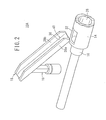
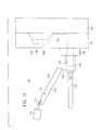
- FIG. 12 is an overall, schematic, side view of a casting apparatus 110 according to the second embodiment.
- the casting apparatus 110 has a cooling jig 118 for guiding a melt 114 from a ladle 112 to a plunger sleeve 116, a plunger tip 120 capable of reciprocating in the plunger sleeve 116, a stationary mold 122 having the plunger sleeve 116, and a movable mold 124 capable of moving toward and away from the stationary mold 122 by using a drive mechanism (not shown).
- the cooling jig 118 is formed as a long object and inclined at 10° to 80°, preferably about 20° to 40°, to the vertical direction, so that the melt 114 is transferred to the plunger sleeve 116 at a predetermined flow rate.
- the upper end of the cooling jig 118 is positioned as a start point in the vicinity of the ladle 112 (see FIG. 12 ), and the lower end is positioned as a terminal facing a melt inlet 126 formed on the upper surface of the plunger sleeve 116 (see FIGS. 12 and 13 ).
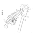
- the cooling jig 118 has a curved shape, which contains a bottom 128 with a first side 130 and a second side 132 extending from the side edges of the bottom 128 (see FIG. 13 ).
- a flow channel 134 is formed on inner walls of the bottom 128, the first side 130, and the second side 132.
- FIG. 14 which is a cross-sectional view taken along the line XIV-XIV in the direction of the arrows in FIG. 13 , the inner wall of the bottom 128 is connected to the inner walls of the first and second sides 130, 132 by R portions (curved portions) 136, 138.
- the curved R portions 136, 138 are formed between the inner walls of the bottom 128 and the first side 130 and between the inner walls of the bottom 128 and the second side 132, respectively.
- the R portions 136, 138 preferably have a curvature radius of 1 to 40 mm. When the curvature radius is less than 1 mm, the R portions 136, 138 tend to be easily heat-cracked. On the other hand, when the curvature radius is more than 40 mm, the contact area between the cooling jig 118 and the melt 114 is reduced to deteriorate the cooling efficiency.
- the R portions 136, 138 more preferably have a curvature radius of 3 to 20 mm.
- FIG. 15 which is a cross-sectional view taken along the line XV-XV in the direction of the arrows in FIG. 13 , an upper portion of the flow channel 134 has a larger width.
- the first and second sides 130, 132 arranged facing each other are inclined such that the distance therebetween is increased with increasing distance from the bottom 128.
- the first and second sides 130, 132 are preferably at an angle ⁇ 1 of 0.25° to 10° to a vertical line M.
- angle ⁇ 1 is less than 0.25°, a residual solid cannot be easily removed from the cooling jig 118 in the rotation step to be hereinafter described.
- angle ⁇ 1 is more than 10°, an insufficiently or excessively cooled portion may be generated in the flow of the melt 114 or semi-solid slurry on the flow channel 134, and the residual solid may be removed and scattered from the cooling jig 118 before the completion of the rotation step.
- the lower end of the bottom 128 acts as a melt outlet, and the length of the bottom 128 decreases in the direction from the inner wall to the outer wall in the lower end.
- an inclined surface 140 is formed in the lower end (the melt outlet) of the bottom 128 to increase the distance between the lower end and the melt inlet 126.
- the inclined surface 140 may be at an inclination angle ⁇ 2 of 60° to the vertical line M.
- the cooling jig 118 having such a structure, at least the inner wall of the bottom 128 (the bottom surface of the flow channel 134) and the R portions 136, 138 have an ten-point average roughness Rz of 6.3 ⁇ m or less.
- the contact area between the wall surfaces of the flow channel 134 and the melt 114 or semi-solid slurry is increased. Therefore, the efficiency of the heat transfer from the melt 114 to the cooling jig 118 is increased, and the size of the cooling jig 118 can be reduced.
- the heat transfer from the melt 114 to the cooling jig 118 can be carried out with high efficiency as described above, the inner wall of the bottom 128 and the R portions 136, 138 are prevented from being heat-cracked.
- the ten-point average roughness Rz is preferably kept as low as possible. However, in the case of excessively reducing the roughness Rz, a precision surface finishing process is required, whereby the cooling jig 118 cannot be efficiently prepared, and the process cost is increased. Thus, the ten-point average roughness Rz may be approximately 1.6 ⁇ m or more.
- the wall surfaces of the first and second sides 130, 132 may have a ten-point average roughness Rz larger than those of the inner wall of the bottom 128 and the R portions 136, 138. Specifically, the wall surfaces may have a ten-point average roughness Rz of approximately 25 ⁇ m. Of course, the ten-point average roughness Rz of the wall surfaces may be equal to those of the inner wall of the bottom 128 and the R portions 136, 138, i.e. within a range of 1.6 to 6.3 ⁇ m.
- the entire cooling jig 118 may be subjected to a nitridation treatment.
- a hardened layer containing a nitride is formed on the surface of the cooling jig 118 to increase the surface hardness. Therefore, even when the heat stress is concentrated, the cooling jig 118 is hardly heat-cracked. Furthermore, the erosion resistance of the cooling jig 118 is improved due to the hardened layer containing the nitride.
- the cooling jig 118 is composed of a Cu-based alloy
- a treatment for forming a nitride film on the entire cooling jig 118 is preferably carried out instead of the nitridation treatment.
- the nitride is preferably CrN or the like. In this case, the erosion resistance of the cooling jig 118 can be improved.
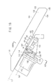
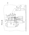
- FIG. 17 is a front view observed in the direction of the arrow A in FIG. 16 .
- a rotary shaft 146 extending from the center of the rotating motor 142 is inserted into a through-hole formed in the supporting plate 144 (see FIG. 13 ).
- a space is formed between the inner wall of the through-hole and the side surface of the rotary shaft 146. Therefore, the supporting plate 144 is not rotated when the rotary shaft 146 is rotated.
- the rotary shaft 146 extends from the through-hole parallel to the axis direction of the cooling jig 118.
- FIG. 19 which is a cross-sectional view taken along the line XIX-XIX in the direction of the arrows in FIG 18 .
- the first gear 148 and the stopper holder 150 are rotated when the rotary shaft 146 is rotated.
- the first gear 148 is engaged with a second gear 154 fitted onto a rotating shaft 152. Therefore, the rotating shaft 152 is rotated by the second gear 154 in response to the rotation of the rotary shaft 146.
- the center of the rotating shaft 152 is at an offset distance from the center of the rotary shaft 146.
- a first bracket 156 and a second bracket 158 having a flat plate shape are fitted at a distance onto the rotating shaft 152.
- the rotating shaft 152 is inserted into a through-hole of each of the first and second brackets 156, 158, so that it is disposed around one side of the first and second brackets 156, 158.
- the cooling jig 118 is firmly press-fitted into and connected to a holder 160 having an approximately C-shaped cross section.
- the first side 130, the bottom 128, and the second side 132 of the cooling jig 118 are firmly fitted into a concave portion 162 of the holder 160.
- the sides of the holder 160 corresponding to the first and second sides 130, 132 are firmly connected by bolts 164 to the outer walls of the first and second sides 130, 132.
- L3 represents the width-direction center axis of the bottom 128 of the cooling jig 118.
- the bottom 128 is divided into two by the center axis L3 along the width direction.
- L4 represents the rotation center axis of the cooling jig 118.
- the cooling jig 118 is rotated on the rotating shaft 152 as described below.
- the rotation center axis L4 of the cooling jig 118 is at an offset distance from the center axis L3 dividing the cooling jig 118 into two along the width direction.
- the stopper holder 150 has a ring-shaped portion 166 and a holding portion 168 extending linearly therefrom.
- a fitting through-hole 170 is formed in the holding portion 168.
- a stopper 172 is firmly fitted into the fitting hole 170, and extends from either side of the fitting hole 170.
- a first blocking member 174 is positioned and fixed in the vicinity of the rotating shaft 152, and a second blocking member 176 is positioned and fixed at an angle of 180° to the first blocking member 174.
- the stopper 172 is in contact with the first blocking member 174.
- the stopper 172 is in contact with the second blocking member 176 (see FIG. 22 ).
- the plunger sleeve 116 has an approximately cylindrical shape and has the melt inlet 126 on the upper surface as described above.
- the plunger tip 120 inserted into the plunger sleeve 116 is connected by a rod 178 to an oil hydraulic cylinder (not shown) and thereby can be reciprocated by the oil hydraulic cylinder.
- a connecting board 180 is disposed between the plunger sleeve 116 and the stationary mold 122.
- a runner 184 for guiding the semi-solid slurry extends in the vertical direction in the stationary mold 122.
- a concave portion 186 is caved and formed on the surface facing the movable mold 124.
- a convex portion 188 is projected and formed on the surface facing the stationary mold 122 in a position corresponding to the concave portion 186.
- the height of the convex portion 188 is slightly smaller than the depth of the concave portion 186, so that a clearance is formed between the bottom surface of the concave portion 186 and the top surface of the convex portion 188.
- the clearance acts as a cavity 190.
- the runner 184 extends toward the cavity 190 in an approximately vertical direction in the vicinity of the contact surface between the stationary mold 122 and the movable mold 124. Thus, the semi-solid slurry is introduced through the runner 184 to the cavity 190.
- the casting apparatus 110 of the second embodiment has the above described basic structure containing the cooling jig 118.
- the advantageous function effects of the cooling jig 118 in operation of the casting apparatus 110 will be described below.
- a release agent is applied to the inner walls of the bottom 128 and the first and second sides 130, 132 of the flow channel 134 in the cooling jig 118 (see FIG. 13 ).
- the application may be carried out in accordance with the above first embodiment.
- the ladle 112 is inclined, whereby the melt 114 of a metal such as an aluminum alloy contained in the ladle 112 is poured into the flow channel 134 in the vicinity of the upper end of the cooling jig 118.
- the cooling jig 118 is inclined preferably at 10° to 80°, more preferably at 20° to 40°, to the vertical direction. At such an inclination angle, the melt 114 can be flowed at an appropriate flow rate on the flow channel 134, so that the flow of the melt 114 can be satisfactorily brought into contact with the cooling jig 118 without gas incorporation.
- the contact area between the melt 114 and the cooling jig 118 can be increased to improve the heat transfer from the melt 114 to the cooling jig 118.
- the angle ⁇ 1 is preferably 0.25° to 10° (see FIG. 15 ), an insufficiently or excessively cooled portion is not generated in the melt 114.
- the heat of the melt 114 is satisfactorily transferred at an appropriate rate to the cooling jig 118, and the temperature of the melt 114 is lowered during the flowage toward the lower end of the cooling jig 118.
- a solid phase is gradually crystallized in the melt 114 during the temperature decrease, to provide the semi-solid slurry.
- the cooling jig 118 draws heat from the melt 114, so that a part of the melt 114 is converted to a solid phase.
- the melt 114 is gradually converted to the semi-solid slurry containing both of solid and liquid phases.
- the R portions 136, 138 are formed between the inner walls of the bottom 128 and the first and second sides 130, 132, and the curvature radii of the R portions 136, 138 are preferably 1 to 40 mm, more preferably 3 to 20 mm.
- the cooling jig 118 does not have a sharply bent portion, whereby the R portions 136, 138 and thus the cooling jig 118 can be prevented from heat cracking due to the contact of the melt 114 (or the semi-solid slurry).
- the prevention effect is further improved. This is because the surface hardness of the cooling jig 118 is increased by the nitridation treatment, whereby the heat crack is more effectively prevented even under a concentrated heat stress.
- the flow of the melt 114 (or the semi-solid slurry) is blocked by the first and second sides 130, 132.
- the first and second sides 130, 132 function to prevent the melt 114 (or the semi-solid slurry) from leaking and falling from the side edges of the cooling jig 118.
- the inclined surface 140 is formed in the lower end (the melt outlet) of the bottom 128 to increase the distance between the lower end and the melt inlet 126. Therefore, the lower end of the bottom 128 is excellent in the discharge of the semi-solid slurry (a so-called liquid cutoff). In other words, the semi-solid slurry is prevented from spreading to the outer wall of the bottom 128.
- the plunger tip 120 is moved frontward by the oil hydraulic cylinder.
- the semi-solid slurry in the plunger sleeve 116 is pressed and transferred through the runner 184 into the cavity 190.
- melt 114 is cooled and solidified in the cavity 190 to obtain a casting.
- a so-called mold opening is performed to take out the casting from the cavity 190.
- a part of the slurry may remain on the cooling jig 118 in the form of a liquid droplet or the like on the flow path.
- the supply of the melt 114 is stopped, the remaining part of the slurry is exposed to air and solidified to generate a solid phase.
- the part remains as a residual solid (a metal piece) mainly on the bottom 128 of the cooling jig 118.
- the melt 114 flowing on the cooling jig 118 cannot be sufficiently cooled as described above. Furthermore, the residual solid may cause clogging in the plunger sleeve 116, the runner 184, etc. or quality deterioration of the resultant casting.
- the residual solid remaining on the cooling jig 118 is removed while the semi-solid slurry is transferred to the cavity 190 and then cooled and solidified.
- the rotating motor 142 (see FIGS. 13 and 16 to 18 ) is energized.
- the rotary shaft 146 is rotated by the energization in the arrow direction shown in FIGS. 13 , 16 , and 17 . It is not particularly necessary to completely solidify the residual solid before the start of the rotation.
- the first gear 148 and the stopper holder 150 are rotated in response to the rotation of the rotary shaft 146. Then, the rotary drive force of the rotary shaft 146 is transmitted to the rotating shaft 152 by the second gear 154 engaged with the first gear 148, whereby the rotating shaft 152 is rotated on the rotation center axis L4.
- the holder 160 is firmly connected to the cooling jig 118.
- the cooling jig 118 is rotated in response to the rotation of the first and second brackets 156, 158 and the holder 160.
- the stopper holder 150 is rotated in response to the rotation of the rotary shaft 146. Then, the stopper 172 supported by the stopper holder 150 is moved in the arrow direction shown in FIG. 22 . Thus, the stopper 172 is moved away from the first blocking member 174 toward the second blocking member 176.
- the stopper holder 150 makes a half turn (i.e., it is turned 180°)
- the stopper 172 is brought into contact with the second blocking member 176.
- the stopper 172 is blocked by the contact, whereby the stopper holder 150 and thus the rotary shaft 146 are prevented from further rotating.
- the rotation center axis L4 of the cooling jig 118 is at an offset distance from the center axis L3 of the bottom 128 (see FIGS. 13 , 17 , and 18 ).
- a relatively large centrifugal force acts on the cooling jig 118, whereby an inertial force is applied to the residual solid. Therefore, the residual solid can be easily removed from the cooling jig 118.
- the residual solid can be more easily removed from the cooling jig 118 as it is further cooled and solidified. In other words, the residual solid is not firmly attached to the cooling jig 118. Furthermore, the release agent applied to the cooling jig 118 makes the removal of the residual solid easier.
- the residual solid can be naturally removed from the cooling jig 118 due to the combination of the above effects. Since the width of the flow channel 134 is increased with increasing distance from the bottom 128 as described above, the first and second sides 130, 132 are inclined at an obtuse angle to the bottom 128. Therefore, the residual solid is not fixed between the bottom 128 and the first side 130 and between the bottom 128 and the second side 132, and is not blocked by the first and second sides 130, 132.
- the semi-solid slurry is prevented from spreading to the outer wall of the bottom 128 in the melt outlet. Therefore, the residual solid does not extend from the inner wall to the outer wall of the bottom 128, whereby the residual solid is not engaged with and blocked by the melt outlet.
- the residual solid can be easily dropped off from the cooling jig 118. Since the first and second sides 130, 132 are at a preferred angle ⁇ 1 of 10° or less to the vertical line M, the residual solid is not removed from the cooling jig 118 during the rotation of the cooling jig 118 as described above.
- the dropped residual solid may be introduced to a shooter (not shown) or the like by a guide plate 192 shown in FIGS. 16 and 17 , and then collected and discharged.
- the rotary shaft 146 of the rotating motor 142 is rotated in the direction opposite to the above direction.
- the cooling jig 118 is returned to the initial position as shown by the solid lines in FIGS. 12 , 13 , 16 , and 17 .
- the stopper 172 is brought into contact with the first blocking member 174.
- the cooling jig 118 is prevented by the contact from further rotating from the initial position.
- the melt 114 can be cooled at an appropriate rate while preventing the heat crack of the cooling jig 118, and the residual solid can be easily removed.
- the casting apparatus 110 of the second embodiment can be satisfactorily used in continuous casting operation using only one cooling jig 118.
- the casting apparatus 110 Since the casting apparatus 110 requires only one cooling jig 118 and does not need a large space for placing the rotating motor 142, the casting apparatus 110 can be placed in a small installation space. Thus, there are no particular restrictions on the layout of the structure capable of removing the residual solid from the cooling jig 118.
- the structure of an equipment containing the casting apparatus 110 is not complicated, and the control and regulation items are not increased.
- the casting apparatus 110 having the only one cooling jig 118 can be more easily controlled in operation as compared with an apparatus having plural cooling jigs.
- the temperature control of the casting apparatus 110 can be remarkably simply carried out.
- the regulation of the casting apparatus 110 can be simply carried out with ease in operation.
- cooling jig 118 is rotated by the rotating motor 142 in the second embodiment, as shown by solid and imaginary lines in FIG. 24 , a turning motor 200 corresponding to the turning motor 60 of the first embodiment may be used instead of the rotating motor 142, and the cooling jig 118 may be turned by the turning motor 200. Also in this case, since the cooling jig 118 has the above described shape, the residual solid can be easily removed from the cooling jig 118.
- a rotation center axis L5 is at an offset distance from a longitudinal center axis L6 of the cooling jig 118.
- the width of the cooling jig 118 may be increased with increasing distance from the ladle 112. This makes the removal or drop of the residual solid from the cooling jig 118 easier.
- first and second gears 148, 154, the rotating shaft 152, the stopper 172, the first and second blocking members 174, 176, and the holder 160 may be disposed between the turning motor 200 and the cooling jig 118 as in the structure of FIG. 18 , and the rotating shaft 152 may be rotated by the turning motor 200 to turn the cooling jig 118.
- the rotating shaft 152 may be rotated by the turning motor 200 to turn the cooling jig 118.
- the stopper 172 is not always necessary.
- the circular movement (the rotation or turning) of the cooling jig 118 may be blocked by stopping the rotating motor 142 or the turning motor 200.
- a technology according to the third embodiment relating to a casting apparatus containing a cooling jig, which is circularly movable and thereby capable of easily removing a residual solid, will be described below.
- a structure according to a first example of the third embodiment contains a rotation mechanism for rotating (circularly moving) a cooling jig.
- a rotation mechanism for rotating (circularly moving) a cooling jig is illustrated below.
- FIG. 25 is an overall, schematic, side view showing a casting apparatus 210 according to this embodiment.
- the casting apparatus 210 has a cooling jig 218 for guiding a melt 214 from a ladle 212 to a plunger sleeve 216 (an injection sleeve), a plunger tip 220 (an injection mechanism) capable of reciprocating in the plunger sleeve 216, a stationary mold 222 having the plunger sleeve 216, and a movable mold 224 capable of moving toward and away from the stationary mold 222 by using a drive mechanism (not shown).
- a drive mechanism not shown
- the cooling jig 218 is formed as a long object and inclined at a predetermined angle to the vertical direction, so that the melt 214 is introduced into the plunger sleeve 216 at a predetermined flow rate.
- the upper end of the cooling jig 218 is positioned as a start point in the vicinity of the ladle 212 (see FIG. 25 ), and the lower end is positioned as a terminal facing a melt inlet 226 formed on the upper surface of the plunger sleeve 216 (see FIGS. 25 and 26 ).
- the cooling jig 218 has a curved shape, which contains a bottom 228 with a first side 230 and a second side 232 extending from the side edges of the bottom 228 (see FIG. 26 ).
- the space surrounded by the bottom 228, the first side 230, and the second side 232 acts as a flow channel 234.
- the first and second sides 230, 232 function to prevent the melt 214 (or a semi-solid slurry) from leaking and falling from the side edges of the cooling jig 218.
- the distance between the first and second sides 230, 232 arranged facing each other is increased with increasing distance from the bottom 228.
- a vertically upper portion of the flow channel 234 has a larger width.
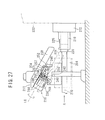
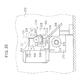
- FIG. 28 is a front view observed in the direction of the arrow A in FIG. 27 .
- a rotary shaft 240 extending from the center of the rotating motor 236 is inserted into a through-hole formed in the supporting plate 238 (see FIG. 26 ).
- a space is formed between the inner wall of the through-hole and the side surface of the rotary shaft 240. Therefore, the supporting plate 238 is not rotated when the rotary shaft 240 is rotated.
- the rotary shaft 240 extends from the through-hole parallel to the longitudinal direction (the axis direction) of the cooling jig 218.
- FIG. 30 which is a cross-sectional view taken along the line XXX-XXX in the direction of the arrows in FIG. 29 .
- the first gear 242 and the stopper holder 244 are rotated when the rotary shaft 240 is rotated.
- the first gear 242 is engaged with a second gear 248 fitted onto a rotating shaft 246 (a parallel shaft). Therefore, the rotating shaft 246 is rotated by the second gear 248 in response to the rotation of the rotary shaft 240.
- the center of the rotating shaft 246 is at an offset distance from the center of the rotary shaft 240.
- a first bracket 250 and a second bracket 252 having a flat plate shape are fitted at a distance onto the rotating shaft 246.
- the rotating shaft 246 is inserted into a through-hole of each of the first and second brackets 250, 252, so that it is disposed around one side of the first and second brackets 250, 252.
- the cooling jig 218 is firmly press-fitted into and connected to a holder 254 having an approximately C-shaped cross section.
- the first side 230, the bottom 228, and the second side 232 of the cooling jig 218 are firmly fitted into a concave portion 256 of the holder 254.
- the sides of the holder 254 corresponding to the first and second sides 230, 232 are firmly connected by bolts 257 to the outer walls of the first and second sides 230, 232.
- L7 represents the width-direction center axis of the bottom 228 of the cooling jig 218.
- the bottom 228 is divided into two by the center axis L7 along the width direction.
- L8 represents the rotation center axis of the cooling jig 218.
- the cooling jig 218 is rotated on the rotating shaft 246 as described below.
- the rotation center axis L8 of the cooling jig 218 is at an offset distance from the center axis L7 dividing the cooling jig 218 into two along the width direction.
- the stopper holder 244 has a ring-shaped portion 258 and a holding portion 260 extending linearly therefrom.
- a fitting through-hole 262 is formed in the holding portion 260.
- a stopper 264 is firmly fitted into the fitting hole 262, and extends from either side of the fitting hole 262.
- a first blocking member 266 is positioned and fixed in the vicinity of the rotating shaft 246, and a second blocking member 268 is positioned and fixed at an angle of 180° to the first blocking member 266.
- the stopper 264 is in contact with the first blocking member 266.
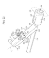
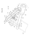
- the stopper 264 is in contact with the second blocking member 268 (see FIG. 31 ).
- the plunger sleeve 216 has an approximately cylindrical shape and has the melt inlet 226 on the upper surface as described above.
- the plunger tip 220 inserted into the plunger sleeve 216 is connected by a rod 270 to an oil hydraulic cylinder (not shown) and thereby can be reciprocated by the oil hydraulic cylinder.
- a connecting board 272 is disposed between the plunger sleeve 216 and the stationary mold 222.
- a runner 276 for guiding the semi-solid slurry extends in the vertical direction in the stationary mold 222.
- a concave portion 278 is caved and formed on the surface facing the movable mold 224.
- a convex portion 280 is projected and formed on the surface facing the stationary mold 222 in a position corresponding to the concave portion 278.
- the height of the convex portion 280 is slightly smaller than the depth of the concave portion 278, so that a clearance is formed between the bottom surface of the concave portion 278 and the top surface of the convex portion 280.
- the clearance acts as a cavity 282.
- the runner 276 extends toward the cavity 282 in an approximately vertical direction in the vicinity of the contact surface between the stationary mold 222 and the movable mold 224. Thus, the semi-solid slurry is introduced through the runner 276 to the cavity 282.
- the casting apparatus 210 of the first example of the third embodiment has the above described basic structure.
- the operation and advantageous function effects of the casting apparatus 210 will be described below with respect to a residual solid removal method.
- a release agent is applied to the inner walls of the bottom 228 and the first and second sides 230, 232 of the flow channel 234 in the cooling jig 218 (see FIG. 26 ). Then, as shown in FIG. 25 , the ladle 212 is inclined, whereby the melt 214 of a metal such as an aluminum alloy contained in the ladle 212 is poured into the flow channel 234 in the vicinity of the upper end of the cooling jig 218.
- the poured melt 214 flows along the flow channel 234 toward the lower end of the inclined cooling jig 218.
- the cooling jig 218 draws heat from the melt 214, so that a part of the melt 214 is converted to a solid phase.
- the melt 214 is gradually converted to the semi-solid slurry containing both of solid and liquid phases while flowing on the cooling jig 218.
- the plunger tip 220 is moved frontward by the oil hydraulic cylinder.
- the semi-solid slurry in the plunger sleeve 216 is pressed and transferred through the runner 276 into the cavity 282.
- melt 214 is cooled and solidified in the cavity 282 to obtain a casting.
- a so-called mold opening is performed to take out the casting from the cavity 282.
- the melt 214 flowing on the cooling jig 218 cannot be sufficiently cooled as described above. Furthermore, the residual solid may cause clogging in the plunger sleeve 216, the runner 276, etc. or quality deterioration of the resultant casting.
- the residual solid remaining on the cooling jig 218 is removed while the semi-solid slurry is transferred to the cavity 282 and then cooled and solidified.
- the rotating motor 236 (see FIGS. 26 to 29 ) is energized.
- the rotary shaft 240 is rotated by the energization in the arrow direction shown in FIGS. 26 to 28 . It is not particularly necessary to completely solidify the residual solid before the start of the rotation.
- the first gear 242 and the stopper holder 244 are rotated in response to the rotation of the rotary shaft 240. Then, the rotary drive force of the rotary shaft 240 is transmitted to the rotating shaft 246 by the second gear 248 engaged with the first gear 242, whereby the rotating shaft 246 is rotated on the rotation center axis L8.
- the holder 254 is firmly connected to the cooling jig 218.
- the cooling jig 218 is rotated in response to the rotation of the first and second brackets 250, 252 and the holder 254.
- the stopper holder 244 is rotated in response to the rotation of the rotary shaft 240. Then, the stopper 264 supported by the stopper holder 244 is moved in the arrow direction shown in FIG. 31 . Thus, the stopper 264 is moved away from the first blocking member 266 toward the second blocking member 268.
- the stopper holder 244 makes a half turn (i.e., it is turned 180°)
- the stopper 264 is brought into contact with the second blocking member 268.
- the stopper 264 is blocked by the contact, whereby the stopper holder 244 and thus the rotary shaft 240 are prevented from further rotating.
- the rotation center axis L8 of the cooling jig 218 is at an offset distance from the center axis L7 of the bottom 228 (see FIGS. 26 and 28 ).
- a relatively large centrifugal force acts on the cooling jig 218, whereby an inertial force is applied to the residual solid. Therefore, the residual solid can be easily removed from the cooling jig 218.
- the residual solid can be more easily removed from the cooling jig 218 as it is further cooled and solidified. In other words, the residual solid is not firmly attached to the cooling jig 218. Furthermore, in the first example of the third embodiment, the release agent applied to the cooling jig 218 makes the removal of the residual solid easier.
- the residual solid can be naturally removed from the cooling jig 218 due to the combination of the above effects. Since the width of the flow channel 234 is increased with increasing distance from the bottom 228 as described above, the first and second sides 230, 232 are inclined at an obtuse angle to the bottom 228. Therefore, the residual solid is not fixed between the bottom 228 and the first side 230 and between the bottom 228 and the second side 232, and is easily dropped off.
- the dropped residual solid may be introduced to a shooter (not shown) or the like by a guide plate 284 shown in FIGS. 27 and 28 , and then collected and discharged.
- the rotary shaft 240 of the rotating motor 236 is rotated in the direction opposite to the above direction.
- the cooling jig 218 is returned to the initial position as shown by the solid lines in FIGS. 25 to 28 .
- the stopper 264 is brought into contact with the first blocking member 266.
- the cooling jig 218 is prevented by the contact from further rotating from the initial position.
- the casting apparatus 210 of the first example can be satisfactorily used in continuous casting operation using only one cooling jig 218.
- the casting apparatus 210 requires only one cooling jig 218 and does not need a large space for placing the rotating motor 236. Therefore, the casting apparatus 210 can be placed in a small installation space. Thus, there are no particular restrictions on the layout of the structure capable of removing the residual solid from the cooling jig 218.
- the structure of an equipment containing the casting apparatus 210 is not complicated, and the control and regulation items are not increased.
- the casting apparatus 210 having the only one cooling jig 218 can be more easily controlled in operation as compared with an apparatus having plural cooling jigs.
- the temperature control of the casting apparatus 210 can be remarkably simply carried out.
- the regulation of the casting apparatus 210 can be simply carried out with ease in operation.
- the rotation angle of the cooling jig 218 is not particularly limited to 180°, and may be optionally selected from 170°, 200°, etc. In this case, the angle between the first and second blocking member 266, 268 may be controlled at 170°, 200°, etc.
- the stopper 264 is not always necessary.
- the rotation of the cooling jig 218 may be blocked by stopping the rotating motor 236.
- the cooling jig 218 may be rotated not on the rotating shaft 246 but on the rotary shaft 240 of the rotating motor 236.
- the rotary shaft 240 may be positioned such that the center thereof is at an offset distance from the center axis L7.
- the rotation center axis L8 of the cooling jig 218 may correspond to the center axis L7 in each case.
- a structure according to the second example of the third embodiment contains a turning mechanism for turning (circularly moving) a cooling jig.
- a turning mechanism for turning for turning (circularly moving) a cooling jig.
- the turning mechanism described below according to the third embodiment contains the same components as those according to the first embodiment (see FIG. 5 ) and the second embodiment (see FIG. 33 ), the same components are represented by the different numerals in the third embodiment.
- FIG. 33 is an overall, schematic, side view showing a casting apparatus 310 according to the second example of the third embodiment.
- the casting apparatus 310 has a cooling jig 318 for guiding a melt 314 from a ladle 312 to a plunger sleeve 316 (an injection sleeve), a plunger tip 320 (an injection mechanism) capable of reciprocating in the plunger sleeve 316, a stationary mold 322 having the plunger sleeve 316, and a movable mold 324 capable of moving toward and away from the stationary mold 322 by using a drive mechanism (not shown).
- a drive mechanism not shown
- the cooling jig 318 is formed as a long object and inclined at a predetermined angle to the vertical direction, so that the melt 314 is introduced into the plunger sleeve 316 at a predetermined flow rate.
- the upper end of the cooling jig 318 is positioned as a start point in the vicinity of the ladle 312 (see FIG. 33 ), and the lower end is positioned as a terminal facing a melt inlet 326 formed on the upper surface of the plunger sleeve 316 (see FIGS. 33 and 34 ).
- the cooling jig 318 has a curved shape, which contains a bottom 328 with a first side 330 and a second side 332 extending from the side edges of the bottom 328 (see FIG. 34 ).
- the space surrounded by the bottom 328, the first side 330, and the second side 332 acts as a flow channel 334.
- the first and second sides 330, 332 function to prevent the melt 314 (or a semi-solid slurry) from leaking and falling from the side edges of the cooling jig 318.
- the distance between the first and second sides 330, 332 arranged facing each other may be constant in the axis direction of the bottom 328.
- a width W1 may be equal to a width W2.
- the distance is smaller in the vicinity of the ladle 312 and larger in the vicinity of the melt inlet 326.
- the width of the flow channel 334 is increased in the upstream-to-downstream direction of the melt 314 (i.e., the widths W1 and W2 in FIG. 34 satisfy the relation of W1 ⁇ W2), is illustrated below.
- FIG. 36 is a front view observed in the direction of the arrow A in FIG. 35 .
- a space is formed between the inner wall of a through-hole and the side surface of a rotary shaft 340. Therefore, the supporting plate 338 is not rotated when the rotary shaft 340 is rotated.
- the rotary shaft 340 extends vertically upward from the through-hole.
- FIG. 38 which is an enlarged view showing a principal part of FIG. 37 , a first gear 342 and a stopper holder 344 are fitted onto the rotary shaft 340. The first gear 342 and the stopper holder 344 are rotated when the rotary shaft 340 is rotated.
- the first gear 342 is engaged with a second gear 348 fitted onto a turning shaft 346 (a vertical shaft). Therefore, the turning shaft 346 is rotated by the second gear 348 in response to the rotation of the rotary shaft 340.
- the center of the turning shaft 346 is at an offset distance from the center of the rotary shaft 340.
- a first bracket 350 and a second bracket 352 are fitted at a distance onto the turning shaft 346 (see FIG. 35 ).
- the first and second brackets 350, 352 have a flat plate shape, and an end of the shape is cut and inclined at an angle corresponding to the inclination angle of the cooling jig 318.
- the turning shaft 346 is inserted into a through-hole of each of the first and second brackets 350, 352, so that it is disposed around one side of the first and second brackets 350, 352.
- the cooling jig 318 is firmly press-fitted into and connected to a holder 354 having an approximately C-shaped cross section.
- the first side 330, the bottom 328, and the second side 332 of the cooling jig 318 are firmly fitted into a concave portion 356 of the holder 354.
- the sides of the holder 354 corresponding to the first and second sides 330, 332 are firmly connected by bolts 357 to the outer walls of the first and second sides 330, 332.
- L9 represents the axis-direction center axis of the bottom 328 of the cooling jig 318.
- the bottom 328 is divided into two by the center axis L9 along the axis direction.
- L10 represents the turning center axis of the cooling jig 318.
- the cooling jig 318 is turned on the turning shaft 346 as described below.
- the turning center axis L10 of the cooling jig 318 is at an offset distance from the center axis L9 dividing the cooling jig 318 into two along the axis direction.
- the stopper holder 344 has a ring-shaped portion 358 and a holding portion 360 extending linearly therefrom.
- a fitting through-hole 362 is formed in the holding portion 360.
- a stopper 364 is firmly fitted into the fitting hole 362, and extends from either side of the fitting hole 362.
- a first blocking member 366 is positioned and fixed in the vicinity of the turning shaft 346, and a second blocking member 368 is positioned and fixed at an angle of approximately 180° to the first blocking member 366.
- the flow channel 334 of the cooling jig 318 faces vertically upward, and the stopper 364 is in contact with the first blocking member 366.
- the stopper 364 is in contact with the second blocking member 368 (see FIG. 39 ).
- the plunger sleeve 316 has an approximately cylindrical shape and has the melt inlet 326 on the upper surface as described above.
- the plunger tip 320 inserted into the plunger sleeve 316 is connected by a rod 370 to an oil hydraulic cylinder (not shown) and thereby can be reciprocated by the oil hydraulic cylinder.
- a connecting board 372 is disposed between the plunger sleeve 316 and the stationary mold 322.
- a runner 376 for guiding the semi-solid slurry extends in the vertical direction in the stationary mold 322.
- a concave portion 378 is caved and formed on the surface facing the movable mold 324.
- a convex portion 380 is projected and formed on the surface facing the stationary mold 322 in a position corresponding to the concave portion 378.
- the height of the convex portion 380 is slightly smaller than the depth of the concave portion 378, so that a clearance is formed between the bottom surface of the concave portion 378 and the top surface of the convex portion 380.
- the clearance acts as a cavity 382.
- the runner 376 extends toward the cavity 382 in an approximately vertical direction in the vicinity of the contact surface between the stationary mold 322 and the movable mold 324. Thus, the semi-solid slurry is introduced through the runner 376 to the cavity 382.
- the casting apparatus 310 of the second example of the third embodiment has the above described basic structure.
- the operation and advantageous function effects of the casting apparatus 310 will be described below with respect to a residual solid removal method.
- a release agent is applied to the inner walls of the bottom 328 and the first and second sides 330, 332 of the flow channel 334 in the cooling jig 318 (see FIG. 34 ). Then, as shown in FIG. 33 , the ladle 312 is inclined, whereby the melt 314 of a metal such as an aluminum alloy contained in the ladle 312 is poured into the flow channel 334 in the vicinity of the upper end of the cooling jig 318.
- the poured melt 314 flows along the flow channel 334 toward the lower end of the inclined cooling jig 318.
- the cooling jig 318 draws heat from the melt 314, so that a part of the melt 314 is converted to a solid phase.
- the melt 314 is gradually converted to the semi-solid slurry containing both of solid and liquid phases while flowing on the cooling jig 318.
- the plunger tip 320 is moved frontward by the oil hydraulic cylinder.
- the semi-solid slurry in the plunger sleeve 316 is pressed and transferred through the runner 376 into the cavity 382.
- melt 314 is cooled and solidified in the cavity 382 to obtain a casting.
- a so-called mold opening is performed to take out the casting from the cavity 382.
- the part remains as a residual solid (a metal piece) mainly on the bottom 328 of the cooling jig 318.
- the melt 314 flowing on the cooling jig 318 cannot be sufficiently cooled as described above. Furthermore, the residual solid may cause clogging in the plunger sleeve 316, the runner 376, etc. or quality deterioration of the resultant casting.
- the residual solid remaining on the cooling jig 318 is removed while the semi-solid slurry is transferred to the cavity 382 and then cooled and solidified.
- the turning motor 336 (see FIGS. 34 to 37 ) is energized.
- the rotary shaft 340 is rotated by the energization in the arrow direction shown in FIGS. 34 to 36 . It is not particularly necessary to completely solidify the residual solid before the start of the rotation.
- the first gear 342 and the stopper holder 344 are rotated in response to the rotation of the rotary shaft 340. Then, the rotary drive force of the rotary shaft 340 is transmitted to the turning shaft 346 by the second gear 348 engaged with the first gear 342, whereby the turning shaft 346 is turned on the turning center axis L10.
- the first and second brackets 350, 352 attached thereto are turned on the turning center axis L10. Furthermore, also the holder 354 connected to the first and second brackets 350, 352 is turned.
- the holder 354 is firmly connected to the cooling jig 318.
- the cooling jig 318 is turned in response to the turning of the first and second brackets 350, 352 and the holder 354.
- the stopper holder 344 is rotated in response to the rotation of the rotary shaft 340. Then, the stopper 364 supported by the stopper holder 344 is moved in the arrow direction shown in FIG. 39 . Thus, the stopper 364 is moved away from the first blocking member 366 toward the second blocking member 368.
- the stopper 364 When the stopper holder 344 makes a quarter turn (i.e., it is turned 90°), the stopper 364 is brought into contact with the second blocking member 368. The stopper 364 is blocked by the contact, whereby the stopper holder 344 and thus the rotary shaft 340 are prevented from further rotating.
- the turning center axis L10 of the cooling jig 318 is at an offset distance from the center axis L9 of the bottom 328 (see FIGS. 34 and 37 ).
- a relatively large centrifugal force acts on the cooling jig 318, whereby an inertial force is applied to the residual solid. Therefore, the residual solid can be easily removed from the cooling jig 318.
- the residual solid can be more easily removed from the cooling jig 318 as it is further cooled and solidified. In other words, the residual solid is not firmly attached to the cooling jig 318. Furthermore, also in the second example, the release agent applied to the cooling jig 318 makes the removal of the residual solid easier.
- the width of the flow channel 334 in the cooling jig 318 is increased in the upstream-to-downstream direction of the melt 314 as described above.
- the width of the flow channel 334 is increased in the opposite direction (i.e., the distance between the first and second sides 330, 332 is decreased in the upstream-to-downstream direction)
- the residual solid when the residual solid is dropped off along the cooling jig 318 inclined downward, the residual solid may be blocked by the first and second sides 330, 332. This problem is not caused in the second example using the above structure.
- the dropped residual solid may be introduced to a shooter (not shown) or the like by a guide plate 384 shown in FIGS. 35 and 36 , and then collected and discharged.
- the rotary shaft 340 of the turning motor 336 is rotated in the direction opposite to the above direction.
- the cooling jig 318 is returned to the initial position as shown by the solid lines in FIGS. 33 to 36 .
- the stopper 364 is brought into contact with the first blocking member 366.
- the cooling jig 318 is prevented by the contact from further turning from the initial position.
- the casting apparatus 310 of the second example can be satisfactorily used in continuous casting operation using only one cooling jig 318.
- the casting apparatus 310 requires only one cooling jig 318 and does not need a large space for placing the turning motor 336. Therefore, the casting apparatus 310 can be placed in a small installation space. Thus, there are no particular restrictions on the layout of the structure capable of removing the residual solid from the cooling jig 318.
- the structure of an equipment containing the casting apparatus 310 is not complicated, and the control and regulation items are not increased.
- the casting apparatus 310 having the only one cooling jig 318 can be more easily controlled in operation as compared with an apparatus having plural cooling jigs.
- the temperature control of the casting apparatus 310 can be remarkably simply carried out.
- the regulation of the casting apparatus 310 can be simply carried out with ease in operation.
- the turning angle of the cooling jig 318 is not particularly limited to 90°, and may be optionally selected from 100°, 180°, etc. In this case, the angle between the first and second blocking member 366, 368 may be appropriately controlled.
- the stopper 364 is not always necessary.
- the turning of the cooling jig 318 may be blocked by stopping the turning motor 336.
- the cooling jig 318 may be turned not on the turning shaft 346 but on the rotary shaft 340 of the turning motor 336.
- the rotary shaft 340 may be positioned such that the center thereof is at an offset distance from the center axis L9.
- the turning center axis L10 of the cooling jig 18 may correspond to the center axis L9 in each case.
- rotating motor 236 and the turning motor 336 are of electrically driven type in the first and second examples, of course a hydraulic rotation or turning mechanism or the like may be used instead thereof.
- the cooling jig 118 of the second embodiment may be used as the cooling jig 218 or 318 of the third embodiment.
- the release agent application method used in the first embodiment may be used in the second and third embodiments.
- a casting apparatus (10A) has a long cooling jig (18) inclined with respect to a vertical direction.
- a melt (34) is supplied to and flowed on a bottom surface (36a) of the cooling jig (18), whereby a solid phase is generated in the melt (34) to obtain a semi-solid slurry (48), and the semi-solid slurry (48) is transferred into and solidified in a cavity (24) of a mold (12) to obtain a casting.
- the casting apparatus (10A) further has a release agent application unit (42), and a release agent (44) is applied by the application unit (42) to the bottom surface (36a) of the cooling jig (18) in a direction toward a supply of the melt (34) at an angle of less than 90° to the bottom surface (36a) before supplying the melt (34) to the cooling jig (18).
Landscapes
- Engineering & Computer Science (AREA)
- Mechanical Engineering (AREA)
- Molds, Cores, And Manufacturing Methods Thereof (AREA)
Abstract
Description
- The present invention relates to a casting method using a cooling jig for generating a solid phase in a melt flow to prepare a semi-solid slurry and a casting apparatus containing the cooling jig.
- In common casting, a cavity formed in a mold is filled with a high-temperature liquid-phase melt. Recently, a semi-solid slurry containing both of solid and liquid phases is occasionally used instead of the melt. For example, as described in Japanese Patent Nos.
3920378 3339333 - Thus obtained semi-solid slurry is poured from the cooling jig into a plunger sleeve of a casting apparatus, and is then transferred from the plunger sleeve to the cavity of the mold.
- After the melt is flowed on the cooling jig, a residual solid generated by the solidification of the melt remains on the cooling jig. When another melt for the next casting is flowed on the cooling jig without removing the residual solid, the melt cannot be sufficiently cooled and the solid phase content of the semi-solid slurry cannot be easily increased to a desired level.
- Furthermore, when the residual solid is poured together with the melt into the plunger sleeve, it may cause clogging. In addition, even if the clogging can be avoided, in case the residual solid is transferred together with the melt to the cavity, the quality of the resultant casting is deteriorated.
- To avoid the above malfunctions, the residual solid should be removed from the cooling jig before the next casting. A release agent is desirably used for readily performing the removal.
- For example, a technology proposed in Japanese Laid-Open Patent Publication No.
2006-305618 - In a case where the release agent is applied to the cooling jig in this manner, the following problems are generally caused.
- When the release agent applied to the cooling jig is splashed or flowed in the melt flow direction, the agent may be introduced into the plunger sleeve placed in the vicinity of the lower end of the cooling jig. In this case, the release agent may be undesirably incorporated into the generated semi-solid metal to increase gas defects in the product.
- A wide variety of release agents have been known. When the release agent is water-soluble or heat-insulating, the following problems are caused.
- In the case of using the water-soluble release agent, water often remains on the cooling jig. When the water is brought into contact with the melt, a water vapor may be generated and splash the melt. Furthermore, the water may be incorporated into the melt and gasified therein, causing a gas defect. As a result, the quality of the resultant product may be significantly deteriorated. To avoid the problem, for example, the cooling jig may be heated to 100°C or higher to evaporate the water. However, the cooling jig having such a high temperature exhibits a deteriorated melt cooling performance disadvantageously.
- In addition, immediately after the water-soluble release agent reaches the cooling jig in the early stage of the application, the release agent may be partially evaporated due to the heat of the cooling jig, generating a vapor around the cooling jig. When the cooling jig is covered with the generated vapor, the vapor may interfere with the release agent application in the later stage of the continuous application.
- This trouble can be solved by increasing the application pressure or amount of the release agent. However, disadvantageously, the excess release agent may be splashed and introduced into the plunger sleeve placed in the vicinity of the lower end of the cooling jig, and the cooling jig may be excessively cooled by the excess release agent. Obviously, the application of the excess release agent results in casting cost increase.
- In above described Japanese Laid-Open Patent Publication No.
2006-305618 - That is, it is difficult to uniformly apply a powder of the BN or the like to the cooling jig. When the predetermined thickness is not realized, the desired semi-solid metal cannot be obtained, and the resultant product cannot have excellent quality.
- When the release agent such as the BN powder is applied in every casting process in the continuous operation, the agent is accumulated on the cooling jig. Therefore, the BN thickness should be automatically controlled every time the metal melt is supplied. In addition, it is remarkably difficult to control the thickness of the coating per se in the continuous operation.
- The above trouble can be solved by cleaning the accumulated release agent. However, in this case, a complicated apparatus is disadvantageously required. Further, when the cleaning takes a long time, the cycle time and the casting cost are increased.
- The cooling jig has to be compact when placed in a small installation space. However, in the case of applying the heat-insulating release agent to the cooling jig as described in Japanese Laid-Open Patent Publication No.
2006-305618 - As described in Japanese Laid-Open Patent Publication No.
2006-305618 - The cooling jig may be used without the release agent. However, in this case, the cooling jig is readily interacted with the melt, causing erosion. Also, the residual solid cannot be easily removed from the cooling jig as described above.
- The cooling jig described in Japanese Patent No.
3920378 - When the melt is flowed on the cooling jig having a simple flat plate shape, the melt leaks from a side of the cooling jig. As described in Japanese Patent No.
3920378 - In the case of using the cooling jig having a trough shape, the semi-solid slurry may be attached to and solidified on the melt outlet end of the cooling jig and generate a relatively large solid aggregate. In this case, it is difficult to remove the residual solid due to the aggregate.
- On the other hand, in the case of using the cooling jig having a pipe shape, only the melt inlet and outlet are opened. Therefore, it is naturally difficult to remove the residual solid.
- Thus, a method described in Japanese Laid-Open Patent Publication No.
10-034307 10-034307 - In the method disclosed in Japanese Laid-Open Patent Publication No.
10-034307 - In addition, due to the plural cooling jigs, an equipment containing the casting apparatus has a complicated structure and increased control and regulation items. Therefore, this method is disadvantageous in that the casting process cannot be continuously repeated with ease.
- A general object of the present invention is to provide a casting method capable of continuously producing a casting with stable quality at reduced production cost in a small equipment without adverse affects on the cycle time.
- A principal object of the present invention is to provide a casting method capable of easily removing an attached residual solid from a cooling member.
- Another object of the present invention is to provide a cooling jig capable of preventing heat crack due to contact with a high-temperature melt and being easy to remove an attached residual solid therefrom.
- A further object of the present invention is to provide a casting apparatus having a removal mechanism capable of easily removing an attached residual solid from a cooling member, and making it possible to continuously repeating a casting process with ease.
- According to an aspect of the present invention, there is provided a casting apparatus comprising a long cooling jig inclined with respect to a vertical direction, wherein a melt is supplied to and flowed on a predetermined surface of the cooling jig, whereby a solid phase is generated in the melt to obtain a semi-solid slurry, and the semi-solid slurry is transferred into and solidified in a cavity of a mold to obtain a casting, and
- the casting apparatus further comprises a release agent application unit for applying a release agent to the predetermined surface of the cooling jig in a direction toward a supply of the melt at an angle of less than 90° to the predetermined surface before supplying the melt to the cooling jig.
- Since the release agent is applied at an angle of less than 90° to the predetermined surface of the cooling jig, the release agent can be prevented from splashing. In addition, since the release agent is applied in a direction toward the melt supply opposite to an injection sleeve or a vessel, it can be prevented from being introduced into the injection sleeve or vessel.
- The release agent application unit preferably contains one or more release agent application nozzles for spraying the release agent along with an air onto the predetermined surface of the cooling jig in a direction toward the melt supply at an angle of less than 90° to the predetermined surface. In this case, the release agent can be uniformly applied in a small thickness.
- The release agent application unit preferably contains, in addition to the release agent application nozzle, an air nozzle for spraying an air toward a lower end of the cooling jig, from which the melt is discharged as the semi-solid slurry. In this case, even when the lower end of the cooling jig faces the injection sleeve or vessel in the step of applying the release agent, the air sprayed from the air nozzle can act as a so-called air curtain to prevent the release agent from being introduced into the injection sleeve or vessel.
- The casting apparatus preferably comprises a jig transfer unit for moving the cooling jig, and at least the position of the cooling jig in the step of supplying the melt is preferably changed by the jig transfer unit from that in the step of applying the release agent. In this case, the lower end of the cooling jig can be moved away from the injection sleeve or vessel in the step of applying the release agent to reliably prevent the release agent from being introduced into the injection sleeve or vessel.
- The release agent application unit preferably contains two or more of the release agent application nozzles, and the inclination angle of a line connecting the application nozzles is preferably approximately equal to that of the predetermined surface of the cooling jig. In this case, the release agent can be uniformly applied in a small thickness on the predetermined surface of the cooling jig efficiently.
- According to another aspect of the present invention, there is provided a casting method, wherein a melt is supplied to and flowed on a predetermined surface of a long cooling jig inclined with respect to a vertical direction, whereby a solid phase is generated in the melt to obtain a semi-solid slurry, and the semi-solid slurry is transferred into and solidified in a cavity of a mold to obtain a casting, and
- the casting method comprises the steps of
- applying a release agent to the predetermined surface of the cooling jig in a direction toward a supply of the melt at an angle of less than 90° to the predetermined surface, and
- supplying the melt to the predetermined surface of the cooling jig after the application of the release agent.
- In the step of applying the release agent, the release agent along with an air are preferably sprayed onto the predetermined surface of the cooling jig in a direction toward the supply of the melt at an angle of less than 90° to the predetermined surface.
- Furthermore, in the step of applying the release agent, at the same time as the spraying of the release agent and the air, an air is preferably sprayed toward a lower end of the cooling jig, from which the melt is discharged as the semi-solid slurry.
- By performing the above steps, a solidified metal piece can be more easily removed from the cooling jig, and the casting can be continuously produced with stable quality.
- As compared with the technology using the heat-insulating release agent, this method is capable of reducing the deterioration of the heat transfer between the cooling jig and the melt, thereby more efficiently cooling the melt. Therefore, the cooling jig can have a compact size in the method. In addition, the semi-solid slurry can have a fine structure due to the reduction of the heat transfer deterioration, resulting in improved product quality.
- In this method, the release agent can be readily applied in continuous operation. Furthermore, it is not necessary to apply an excess amount of the release agent, so that the release agent can be prevented from being introduced into the injection sleeve or vessel. Therefore, the method is capable of producing the casting with stable quality at reduced production cost while preventing gas defect generation.
- According to a further aspect of the present invention, there is provided a cooling jig for cooling a melt flowing thereon, thereby generating a solid phase in the melt to obtain a semi-solid slurry, comprising a bottom, a first side, and a second side, wherein
- the first and second sides bend and extend from the bottom and are arranged facing each other,
- a flow channel for the semi-solid slurry is formed by inner walls of the bottom and the first and second sides, and
- curved portions are formed between the inner walls of the bottom and the first side and between the inner walls of the bottom and the second side, respectively.
- In this cooling jig, the first and second sides are connected only to the bottom. Therefore, the flow channel is exposed, so that a residual solid on the cooling jig can be remarkably easily removed.
- In a case where the cooling jig has a sharply bent portion to be brought into contact with the melt or the semi-solid slurry, a heat stress may be concentrated, generating a heat crack in this portion. Since the cooling jig of the present invention has the curved portions between the inner walls of the bottom and the first and second sides without the sharply bent portion, it can be prevented from heat cracking.
- Thus, the cooling jig of the present invention is excellent in durability and capable of being significantly easy to remove the residual solid thereon.
- The first and second sides extending from the bottom are preferably inclined at an angle of 0.25° to 10° to a vertical line so that the distance between the sides is increased with increasing distance from the bottom. Thus, the first and second sides are preferably at an obtuse inclination angle to the bottom.
- In this case, the residual solid can be prevented from being fixed and remaining between the bottom and the first side and between the bottom and the second side. As a result, the residual solid cannot cause clogging or casting quality deterioration in the successive casting process.
- In addition, an excessively or insufficiently cooled portion is not generated in the melt.
- In this case, the curved portions preferably have a curvature radius of 1 to 40 mm. When the curvature radius is less than 1 mm, the above advantageous effect may be unachievable, and it may be difficult to prevent the heat cracking of the curved portions. On the other hand, when the curvature radius is more than 40 mm, the contact area between the cooling jig and the melt may be reduced, thereby failing to sufficiently cool the melt.
- It is more preferred that the cooling jig having such a structure is capable of rotating on a rotation axis parallel to an axis direction thereof, and an inclined surface is formed at an end of a melt outlet in the bottom so that the length of the bottom decreases in the direction from the inner wall to the outer wall.
- In this case, when the cooling jig is rotated, a surface of the cooling jig, on which the melt flows mainly, can face vertically downward. Since the residual solid is attached to the cooling jig by a relatively small adhesion force, it can be dropped off by this rotation. Thus, the residual solid can be easily removed from the cooling jig.
- Since the inclined surface is formed at the end of the melt outlet, the semi-solid slurry can be prevented from wrapping around from the inner wall (the bottom surface of the flow channel) to the outer wall of the bottom. Therefore, the residual solid does not extend from the inner wall to the outer wall of the bottom, whereby the residual solid is not engaged with and blocked by the melt outlet.
- Thus, an aggregate of the residual solid is not formed on the melt outlet, and the residual solid can be easily removed.
- The inner wall of the bottom and the curved portions preferably have a ten-point average roughness Rz of 6.3 µm or less (see JIS B 0601-1994). In this case, the contact area between the melt and the cooling jig is increased, and the heat of the melt can be rapidly transferred to the cooling jig. Thus, the efficiency of the heat transfer from the melt to the cooling jig is increased, and the semi-solid slurry can be easily prepared with a desired solid phase content.
- The cooling jig may contain an Fe-based alloy such as a steel. In this case, a hardened layer is preferably formed on a surface of the cooling jig by a nitridation treatment to increase the surface hardness. The cooling jig having the hardened layer is further hardly heat-cracked, and thus has a further improved durability. In addition, the erosion resistance of the cooling jig can be improved by forming the hardened layer in the nitridation treatment.
- The cooling jig may contain a Cu-based alloy. In this case, a film of a nitride such as CrN is preferably formed on a surface of the cooling jig to improve the erosion resistance of the cooling jig.
- In addition, a refrigerant is preferably circulated in the cooling jig to improve the erosion resistance.
- According to a further aspect of the present invention, there is provided a method for removing a residual solid, which is generated on a long cooling jig inclined with respect to a vertical direction when a melt is flowed on a predetermined surface of the cooling jig, whereby a solid phase is generated in the melt to obtain a semi-solid slurry, and the semi-solid slurry is transferred into and solidified in a cavity to obtain a casting, wherein the cooling jig is circularly moved on an axis to drop the residual solid.
- For example, the circular movement may be a rotation movement on a parallel axis extending parallel to an axis direction of the cooling jig. The residual solid can be dropped off by rotating the cooling jig such that the predetermined surface faces vertically downward.
- Thus, in this case, when the cooling jig is rotated, a surface of the cooling jig, on which the melt flows mainly, faces vertically downward. The residual solid is attached to the cooling jig by a relatively small adhesion force, and thereby can be dropped off by this rotation. Thus, the residual solid can be easily removed from the cooling jig.
- The parallel axis may be equal to or different from an axis of a rotary shaft in a rotation mechanism for rotating the cooling jig.
- In each case, in the rotation of the cooling jig, the rotation center of the parallel axis is preferably at an offset distance from a width-direction center axis of the surface of the cooling jig, on which the melt flows mainly. As a result, a relatively large centrifugal force acts on the surface and thus the residual solid. Therefore, the rotation makes the peeling and removal of the residual solid easier.
- In another specific example, the circular movement may be a turning movement on a vertical axis extending in a vertical direction. The residual solid can be dropped off by turning the cooling jig to apply an external force to the residual solid.
- Thus, in this case, when the cooling jig is turned, the external force (mainly a centrifugal force) is applied to the residual solid on the cooling jig. The residual solid is attached to the cooling jig by a relatively small adhesion force and thereby can be readily dropped off (i.e. removed) by external force.
- The vertical axis may be equal to or different from an axis of a rotary shaft in a turning mechanism for turning the cooling jig.
- In each case, in the turning of the cooling jig, the turning center of the vertical axis is preferably at an offset distance from an axis-direction center axis of the surface of the cooling jig, on which the melt flows mainly. As a result, a relatively large external force (such as a centrifugal force) acts on the surface and thus the residual solid. Therefore, the turning makes the peeling and removal of the residual solid easier.
- As described above, the residual solid can be removed from the cooling jig by circularly moving (e.g. rotating or turning) the cooling jig after the transfer of the semi-solid slurry to the injection sleeve. The removal can be carried out while the semi-solid slurry is transferred to the cavity and then cooled and solidified. Therefore, a casting process can be continuously repeated by using only one cooling jig. This is because the residual solid can be removed from the cooling jig before the melt is poured into the injection sleeve in the second casting process, and the residual solid does not cause clogging or casting quality deterioration.
- In addition, in this case, the structure of an equipment containing the casting apparatus is not complicated, and the control and regulation items are not increased. This is because a plurality of cooling jigs are not needed as described above. Thus, the regulation and control (such as a cooling jig temperature control) of the casting apparatus can be easily carried out in operation.
- According to a further aspect of the present invention, there is provided a casting apparatus comprising
- a long cooling jig for cooling a melt flowing thereon, thereby generating a solid phase in the melt to obtain a semi-solid slurry,
- an injection sleeve into which the semi-solid slurry is poured from the cooling jig,
- an injection mechanism for injecting the semi-solid slurry contained in the injection sleeve, and
- a mold having a cavity into which the semi-solid slurry is introduced by pressure of the injection mechanism, wherein
- the casting apparatus further comprises a circular movement mechanism for circularly moving the cooling jig, and
- the cooling jig is circularly moved by the circular movement mechanism.
- For example, the circular movement mechanism may be a rotation mechanism having a rotary shaft extending parallel to an axis direction of the cooling jig inclined with respect to a vertical direction.
- In such a structure, when the rotation mechanism is energized, the cooling jig is rotated so that a surface of the cooling jig, on which the melt flows mainly, faces vertically downward. As described above, the residual solid can be easily removed from the cooling jig by the rotation.
- As described above, the rotation center (the parallel axis) of the cooling jig may be an axis of the rotary shaft of the rotation mechanism or an axis of another shaft extending in the vertical direction.
- In each case, the rotation center of the cooling jig is preferably at an offset distance from a width-direction center axis of the surface of the cooling jig, on which the melt flows mainly. As a result, as described above, a relatively large centrifugal force acts on the residual solid. Therefore, the rotation makes the removal of the residual solid easier.
- It is preferred that the casting apparatus further comprises a stopper movable in response to the rotation of the cooling jig and a blocking member for blocking the stopper in contact therewith, and the rotation of the cooling jig is stopped when the stopper is brought into contact with the blocking member.
- In this case, when the stopper is brought into contact with the blocking member, an impact load is generated. The impact load is transmitted from the cooling jig to the residual solid. Therefore, the impact load makes the removal of the residual solid easier.
- It is preferred that the cooling jig has a flow channel for the melt, and the width of the flow channel increases in a vertically upward direction. In this case, when the cooling jig is rotated, the width of the flow channel increases in a vertically downward direction. Therefore, the residual solid can be easily dropped off from the cooling jig.
- In another specific example, the circular movement mechanism may be a turning mechanism having a rotary shaft extending in a vertical direction.
- In such a structure, when the turning mechanism is energized, the cooling jig is turned so that an external force such as a centrifugal force is applied to the residual solid remaining on the cooling jig. As described above, the residual solid can be easily removed from the cooling jig by the external force.
- As described above, the turning center (the vertical axis) of the cooling jig may be an axis of the rotary shaft of the turning mechanism or an axis of another shaft extending in the vertical direction.
- In each case, the turning center of the cooling jig is preferably at an offset distance from an axis-direction center axis of the surface of the cooling jig, on which the melt flows mainly. As a result, as described above, a relatively large centrifugal force acts on the residual solid. Therefore, the turning makes the removal of the residual solid from the cooling jig easier.
- It is preferred that the casting apparatus further comprises a stopper movable in response to the turning of the cooling jig and a blocking member for blocking the stopper in contact therewith, and the turning of the cooling jig is stopped when the stopper is brought into contact with the blocking member.
- In this case, when the stopper is brought into contact with the blocking member, an impact load is generated. The impact load is transmitted from the cooling jig to the residual solid. Therefore, the impact load makes the removal of the residual solid from the cooling jig easier.
- In a case where the width of the cooling jig is decreased in the upstream-to-downstream direction of the melt, when the residual solid is dropped off along the cooling jig inclined vertically downward, the residual solid may be blocked by the narrow lower portion of the cooling jig. To solve the problem, the width of the cooling jig preferably increases in the upstream-to-downstream direction of the melt.
- Thus, in this case, the residual solid can be easily slid advantageously.
- In each case of using the rotation or turning, one cooling jig is appropriately subjected to the above removal process, and a plurality of cooling jigs are not needed. Thus, it is not necessary to increase the size of an equipment containing the casting apparatus.
- The casting apparatus requires only one cooling jig to satisfactorily perform the casting process, and therefore has a simple overall structure. Thus, the casting apparatus does not need a large installation space.
- The above and other objects features and advantages of the present invention will become more apparent from the following description when taken in conjunction with the accompanying drawings in which a preferred embodiment of the present invention is shown by way of illustrative example.
-
-
FIG. 1 is a structural view showing a first casting apparatus; -
FIG. 2 is an enlarged perspective view showing a cooling jig and vicinity thereof in the first casting apparatus; -
FIG. 3 is a structural view showing an example of a release agent application unit; -
FIG. 4 is a flow chart of a first casting method; -
FIG. 5 is an enlarged perspective view showing a cooling jig and vicinity thereof in a second casting apparatus; -
FIG. 6 is a flow chart of a second casting method; -
FIG. 7 is an enlarged perspective view showing a cooling jig and vicinity thereof in a third casting apparatus; -
FIG. 8 is a flow chart of a third casting method; -
FIG. 9 is a characteristic chart showing the change with time in the temperature of a supplied melt in a cooling jig outlet (the outlet melt temperature) in each of Example and Comparative Example; -
FIG. 10 is a characteristic chart showing the average outlet melt temperature in each of Example and Comparative Example; -
FIG. 11 is a characteristic chart showing the change with time in the difference from the initial cooling jig temperature in each of Example and Comparative Example; -
FIG. 12 is an overall, schematic, side view showing a casting apparatus according to a second embodiment; -
FIG. 13 is an enlarged perspective view showing a cooling jig and vicinity thereof in the casting apparatus; -
FIG. 14 is a cross-sectional view taken along the line XIV-XIV in the direction of the arrows inFIG. 13 ; -
FIG. 15 is a cross-sectional view taken along the line XV-XV in the direction of the arrows inFIG. 13 ; -
FIG. 16 is a schematic side view showing a principal part of the casting apparatus; -
FIG. 17 is a schematic front view observed in the direction of the arrow A inFIG. 16 ; -
FIG. 18 is an enlarged side view showing a principal part ofFIG. 16 ; -
FIG. 19 is a cross-sectional view taken along the line XIX-XIX in the direction of the arrows inFIG 18 ; -
FIG. 20 is a width-direction cross-sectional view showing an insufficiently cooled portion generated in the vicinity of the width-direction center surface of a melt on a flow channel of the cooling jig; -
FIG. 21 is a width-direction cross-sectional view showing an excessively cooled portion generated in a contact area between the melt and a bottom inner wall and an insufficiently cooled portion generated in the vicinity of the width-direction center surface of the melt on the cooling jig; -
FIG. 22 is a cross-sectional view showing a stopper turned 180° from the position shown inFIG. 19 ; -
FIG. 23 is an enlarged perspective view showing the cooling jig inverted from the position shown inFIG. 13 ; -
FIG. 24 is an overall, schematic, perspective view showing a casting apparatus according to a modified example of the second embodiment; -
FIG. 25 is an overall, schematic, side view showing a casting apparatus according to an embodiment of the present invention; -
FIG. 26 is an enlarged perspective view showing a cooling jig and vicinity thereof in the casting apparatus; -
FIG. 27 is a schematic side view showing a principal part of the casting apparatus; -
FIG 28 is a schematic front view observed in the direction of the arrow A inFIG. 27 ; -
FIG. 29 is an enlarged side view showing a principal part ofFIG. 27 ; -
FIG. 30 is a cross-sectional view taken along the line XXX-XXX in the direction of the arrows inFIG. 29 ; -
FIG. 31 is a cross-sectional view showing a stopper turned 180° from the position shown inFIG. 30 ; -
FIG. 32 is an enlarged perspective view showing the cooling jig inverted from the position shown inFIG. 26 ; -
FIG. 33 is an overall, schematic, side view showing a casting apparatus according to an embodiment of the present invention; -
FIG. 34 is an enlarged perspective view showing a cooling jig and vicinity thereof in the casting apparatus; -
FIG. 35 is a schematic side view showing a principal part of the casting apparatus; -
FIG. 36 is a schematic front view observed in the direction of the arrow A inFIG. 35 ; -
FIG. 37 is a partially cutaway plan view showing the cooling jig ofFIG. 34 before turning; -
FIG. 38 is an enlarged side view showing a principal part ofFIG. 37 ; -
FIG. 39 is a cross-sectional view showing a stopper turned 90° from the position shown inFIG. 38 ; and -
FIG 40 is a partially cutaway plan view showing the cooling jig turned 90° from the position shown inFIG. 37 . - Several preferred embodiments of the casting method and the related casting apparatus used therein of the present invention will be described in detail below with reference to the accompanying drawings.
- First, a technology according to a first embodiment for applying a release agent will be described below using the examples of a
first casting apparatus 10A (seeFIG. 1 ), asecond casting apparatus 10B (seeFIG. 5 ), and a third casting apparatus 10C (seeFIG. 7 ). - As shown in
FIG. 1 , thefirst casting apparatus 10A has amold 12, aplunger sleeve 14, aplunger tip 16, and a coolingjig 18. - The
mold 12 contains amovable mold portion 20 and astationary mold portion 22. Themovable mold portion 20 can be moved in the direction toward and away from thestationary mold portion 22. When themovable mold portion 20 is combined with thestationary mold portion 22 into the closed state, acavity 24 is divided and formed as a casting space therebetween. - The
plunger sleeve 14 has a cylindrical shape containing ahollow portion 26. The end of theplunger sleeve 14 is inserted and connected to thestationary mold portion 22 by a connectingportion 28, whereby thehollow portion 26 is connected to thecavity 24 of themold 12 by adistributor 30 in themovable mold portion 20 and arunner 31 in thestationary mold portion 22. The posterior end of theplunger sleeve 14 has an opening, into which theplunger tip 16 is inserted. Amelt inlet 32 is formed on an upper side of theplunger sleeve 14 in the vicinity of the posterior end. - The
plunger tip 16 can be moved in thehollow portion 26 of theplunger sleeve 14 in the direction toward and away from themold 12. - The cooling
jig 18 is formed as a long object and inclined at a predetermined angle to the vertical direction on a supportingmember 19, so that amelt 34 is transferred from aladle 33 to theplunger sleeve 14 at a predetermined flow rate. The lower end of the coolingjig 18 is arranged facing themelt inlet 32 of theplunger sleeve 14. - In this case, as shown in
FIG. 2 , the coolingjig 18 has a curved shape, which contains a bottom 36 with afirst side 38a and asecond side 38b extending from the side edges of the bottom 36. The space surrounded by the bottom 36, thefirst side 38a, and thesecond side 38b acts as aflow channel 40. The first andsecond sides jig 18. - As shown in
FIG. 3 , thefirst casting apparatus 10A further has a releaseagent application unit 42, which functions to apply a release agent to the flow channel of the coolingjig 18 before supplying themelt 34 to the coolingjig 18. The release agent is applied in a direction toward the supply of the melt 34 (the upper end of the cooling jig 18) at an angle θ of less than 90° to abottom surface 36a (a predetermined surface) of the flow channel. - The release
agent application unit 42 contains two release agent application nozzles (a first releaseagent application nozzle 46a and a second releaseagent application nozzle 46b) for spraying arelease agent 44 and an air toward the upper end of the coolingjig 18 at the angle θ of less than 90° to thebottom surface 36a of the coolingjig 18, an air nozzle 52 (shown by a two-dot chain line) for spraying anair 50 toward the lower end of the cooling jig 18 (from which themelt 34 is discharged as the semi-solid slurry 48 (seeFIG. 1 )), and asupport 54 for fixing the first releaseagent application nozzle 46a, the second releaseagent application nozzle 46b, and theair nozzle 52 at the same angle θ to thebottom surface 36a of the coolingjig 18. The inclination angle φa of a line connecting the first and second releaseagent application nozzles support 54 to the vertical direction is approximately equal to the inclination angle φb of thebottom surface 36a of the coolingjig 18 to the vertical direction. - A casting method using the
first casting apparatus 10A (hereinafter referred to as the first casting method) will be described with reference to the flow chart ofFIG. 4 . - In the step S1 of
FIG. 4 , themovable mold portion 20 is moved and combined with the stationary mold portion 22 (mold closing). In this step, theisolated cavity 24 is formed in themold 12. - In the step S2, as shown in
FIG. 3 , therelease agent 44 and the air are sprayed from the first and second releaseagent application nozzles release agent 44 onto thebottom surface 36a of the coolingjig 18. In addition, in the step S2, theair 50 is sprayed from theair nozzle 52 toward the lower end of the coolingjig 18. - In the step S3, the application of the
release agent 44 from the first and second releaseagent application nozzles air 50 from theair nozzle 52 are stopped. - In the step S4, the
melt 34 is supplied (poured) to the upper end of the coolingjig 18. The suppliedmelt 34 flows toward the lower end of theinclined cooling jig 18 along the flow channel 40 (seeFIG. 2 ). In this step, the coolingjig 18 draws heat from themelt 34, so that a part of themelt 34 is converted to a solid phase. Thus, themelt 34 is gradually converted to thesemi-solid slurry 48 containing both of solid and liquid phases during the flowing on the coolingjig 18. Most of thesemi-solid slurry 48 is transferred from theflow channel 40 through themelt inlet 32 into theplunger sleeve 14. - In the step S5, when a predetermined amount of the
semi-solid slurry 48 is put in theplunger sleeve 14, theplunger tip 16 is moved frontward (toward the mold 12). Thus, thesemi-solid slurry 48 in theplunger sleeve 14 is transferred through thedistributor 30 and therunner 31 into thecavity 24 of themold 12. - Then, the
semi-solid slurry 48 is cooled and solidified in thecavity 24 to obtain a casting. In the step S6, a so-called mold opening is performed to take out the casting from thecavity 24. - In the
first casting apparatus 10A and the first casting method, since therelease agent 44 is sprayed toward the upper end of the cooling jig 18 (the supply of the melt 34) at the angle θ of less than 90° to thebottom surface 36a before supplying themelt 34 in this manner, therelease agent 44 is applied at the angle θ of less than 90° to thebottom surface 36a and thereby can be prevented from splashing. In addition, since therelease agent 44 is applied in a direction toward the supply of themelt 34 opposite to theplunger sleeve 14 or a vessel, therelease agent 44 can be prevented from being introduced into theplunger sleeve 14 or vessel. - Particularly in the
first casting apparatus 10A, since the two release agent application nozzles (the first and second releaseagent application nozzles release agent 44 and the air, therelease agent 44 can be uniformly applied in a small thickness. - Since the
air nozzle 52 for spraying theair 50 toward the lower end of the coolingjig 18 is used in addition to the first and second releaseagent application nozzles jig 18 faces theplunger sleeve 14 or vessel in the step of applying therelease agent 44, theair 50 sprayed from theair nozzle 52 can act as a so-called air curtain to prevent therelease agent 44 from being introduced into theplunger sleeve 14 or vessel. Furthermore, since the spraying of theair 50 from theair nozzle 52 toward the lower end of the coolingjig 18 is carried out at the same time as the application of therelease agent 44 using the first and second releaseagent application nozzles release agent 44 is splashed on the coolingjig 18 in the application step, the splashedrelease agent 44 can be efficiently prevented by theair 50 from being introduced into theplunger sleeve 14 or vessel. - Since the inclination angle φa of the line connecting the first and second release
agent application nozzles bottom surface 36a of the coolingjig 18, therelease agent 44 can be uniformly applied in a small thickness on thebottom surface 36a efficiently. - Several preferred conditions for the application of the
release agent 44 will be described below. - The
release agent 44 has to be uniformly applied in a small thickness to thebottom surface 36a of the cooling jig 18 (the flow channel 40) so that themelt 34 is prevented from being baked and attached onto the coolingjig 18 while not inhibiting the heat transfer between themelt 34 and the coolingjig 18. Therefore, it is preferred that therelease agent 44 is sprayed from the first and second releaseagent application nozzles - (1-1) The first and second release
agent application nozzles release agent 44 and the air. - (1-2) The first and second release
agent application nozzles - (1-3) The first and second release
agent application nozzles - (1-4) The spray pattern of the
release agent 44 formed by the first and second releaseagent application nozzles release agent 44 applied onto thebottom surface 36a of the cooling jig 18) is a circular shape, an ellipsoidal shape, a multiround shape (a shape containing a plurality of circular islands arranged in a circle), a flat shape (a shape containing end curved portions and a rectangle therebetween) so that therelease agent 44 can be uniformly applied in a small thickness to thebottom surface 36a of the coolingjig 18 while reducing undesired application to a portion other than the coolingjig 18. - (1-5) The first and second release
agent application nozzles jig 18. And they are each at a minimum distance of 10 to 2000 mm to thebottom surface 36a of the coolingjig 18 so that therelease agent 44 can be uniformly applied in a small thickness to thebottom surface 36a while reducing undesired application to a portion other than the coolingjig 18. - (1-6) Though the two release agent application nozzles (the first and second release
agent application nozzles agent application nozzle 46a) may be moved toward the lower or upper end of the coolingjig 18 while maintaining the angle θ to apply therelease agent 44. - (2-1) The application amount of the
release agent 44 is 0.1 to 5 cc per 1 cycle so that the heat transfer between themelt 34 and the coolingjig 18 is not inhibited by therelease agent 44 and the gasifiedrelease agent 44 is prevented from being introduced into themelt 34. This number range is preferred when the coolingjig 18 has an entire length of 1000 mm and a width of 120 mm. - (2-2) The application amount of the
release agent 44 is controlled by selecting the application time or the application flow rate to reduce the variation in each cycle of the continuous operation. - It is preferred that the heat transfer between the cooling
jig 18 and themelt 34 is not inhibited by therelease agent 44 to efficiently cool themelt 34. Therefore, therelease agent 44 is preferably a water-insoluble agent having a heat transfer coefficient of 6 kW/m2K or more, further preferably an oil-based agent having a heat transfer coefficient of 8 kW/m2K or more. - Next, the
second casting apparatus 10B having a jig transfer unit will be described below with reference toFIGS. 5 and6 . - Though the structure of the
second casting apparatus 10B is approximately equal to that of the abovefirst casting apparatus 10A, thesecond casting apparatus 10B is different from thefirst casting apparatus 10A in that ajig transfer unit 56 is disposed. The coolingjig 18 is moved by thejig transfer unit 56 at least such that the position of the coolingjig 18 in the step of supplying themelt 34 is different from that in the step of applying therelease agent 44. Particularly, thejig transfer unit 56 of thesecond casting apparatus 10B contains aturning device 58 for turning the coolingjig 18 on a rotation axis extending in the vertical direction. - The turning
device 58 contains a turningmotor 60 in the supportingmember 19. Arotary shaft 62 of the turningmotor 60 extends upward in the vertical direction, and the end thereof is connected to an outer wall of the upper end in the coolingjig 18. - In
FIG. 5 , L1 represents a width-direction center line of the bottom 36 of the coolingjig 18. Thus, the bottom 36 is divided into two by the center line L1 along the axis. As shown inFIG. 5 , therotary shaft 62 is connected to the vicinity of the upper end of the coolingjig 18, whereby the coolingjig 18 is turned on a rotation axis L2. As is clear fromFIG. 5 , the rotation axis L2 of the coolingjig 18 is at an offset distance from the center line L1. - When the
melt 34 is supplied to the coolingjig 18, as shown by a solid line inFIG. 5 , the coolingjig 18 is turned to a position in which the lower end of the coolingjig 18 faces themelt inlet 32 of theplunger sleeve 14. On the other hand, when therelease agent 44 is applied to the coolingjig 18 by the first and second releaseagent application nozzles FIG. 3 ), as shown by a two-dot chain line inFIG. 5 , the coolingjig 18 is turned to a position in which the lower end of the coolingjig 18 is distant from themelt inlet 32 of the plunger sleeve 14 (an initial position). In thesecond casting apparatus 10B, therelease agent 44 is not introduced into theplunger sleeve 14 or vessel in the application step, and thus theair nozzle 52 shown inFIG. 3 is not needed. - A casting method using the
second casting apparatus 10B (hereinafter referred to as the second casting method) will be described with reference to the flow chart ofFIG. 6 . It should be noted that the lower end of the coolingjig 18 is in the initial position. - In the step S101 of
FIG. 6 , themovable mold portion 20 is moved and combined with the stationary mold portion 22 (mold closing). In this step, theisolated cavity 24 is formed in themold 12. - In the step S102, when the lower end of the cooling
jig 18 is in the initial position, therelease agent 44 and the air are sprayed from the first and second releaseagent application nozzles release agent 44 onto thebottom surface 36a of the coolingjig 18. - In the step S 103, the application of the
release agent 44 from the first and second releaseagent application nozzles - In the step S104, the cooling
jig 18 is turned to a position in which the lower end faces themelt inlet 32 of theplunger sleeve 14. - In the step S105, the
melt 34 is supplied (poured) to the upper end of the coolingjig 18. The suppliedmelt 34 flows toward the lower end of theinclined cooling jig 18 along the flow channel 40 (seeFIG. 2 ), and the resultantsemi-solid slurry 48 is transferred into theplunger sleeve 14. - In the step S106, when a predetermined amount of the
semi-solid slurry 48 is put in theplunger sleeve 14, theplunger tip 16 is moved frontward (toward the mold 12). Thus, thesemi-solid slurry 48 in theplunger sleeve 14 is transferred into thecavity 24 of themold 12. - Then, the
semi-solid slurry 48 is cooled and solidified in thecavity 24 to obtain a casting. In the step S107, a so-called mold opening is performed to take out the casting from thecavity 24. - In the
second casting apparatus 10B and second casting method, since the coolingjig 18 is turned by the turningdevice 58 such that the lower end thereof is placed in the position distant from themelt inlet 32 of theplunger sleeve 14 or vessel (the initial position) before supplying themelt 34, therelease agent 44 is not introduced into theplunger sleeve 14 or vessel in the application step. In addition, since theair nozzle 52 is not needed, the casting space can be saved and the air supply system can be simplified. - Next, the third casting apparatus 10C having another jig transfer unit will be described below with reference to
FIGS. 7 and8 . - Though the structure of the third casting apparatus 10C is approximately equal to that of the above
second casting apparatus 10B, the third casting apparatus 10C is different from thesecond casting apparatus 10B in that thejig transfer unit 56 contains a horizontally movingdevice 64 for moving the coolingjig 18 in the horizontal direction while maintaining the inclination angle φb. The horizontally movingdevice 64 may contain a common oil hydraulic cylinder, a robot, etc. - When the
melt 34 is supplied to the coolingjig 18, as shown by a two-dot chain line inFIG. 7 , the coolingjig 18 is moved in the horizontal direction to a position in which the lower end of the coolingjig 18 faces themelt inlet 32 of theplunger sleeve 14 while maintaining the inclination angle φb. On the other hand, when therelease agent 44 is applied to the coolingjig 18 by the first and second releaseagent application nozzles FIG. 3 ), as shown by a solid line inFIG. 7 , the coolingjig 18 is moved in the horizontal direction to a position in which the lower end of the coolingjig 18 is distant from themelt inlet 32 of the plunger sleeve 14 (an initial position) while maintaining the inclination angle φb. In the third casting apparatus 10C, therelease agent 44 is not introduced into theplunger sleeve 14 or vessel in the application step, and thus theair nozzle 52 shown inFIG. 3 is not needed. - A casting method using the third casting apparatus 10C (hereinafter referred to as the third casting method) will be described with reference to the flow chart of
FIG. 8 . It should be noted that the lower end of the coolingjig 18 is in the initial position. - In the step S201 of
FIG. 8 , themovable mold portion 20 is moved and combined with the stationary mold portion 22 (mold closing). In this step, theisolated cavity 24 is formed in themold 12. - In the step S202, when the lower end of the cooling
jig 18 is in the initial position, therelease agent 44 and the air are sprayed from the first and second releaseagent application nozzles release agent 44 onto thebottom surface 36a of the coolingjig 18. - In the step S203, the application of the
release agent 44 from the first and second releaseagent application nozzles - In the step S204, the cooling
jig 18 is moved in the horizontal direction to a position in which the lower end faces themelt inlet 32 of theplunger sleeve 14 while maintaining the inclination angle φb. - In the step S205, the
melt 34 is supplied (poured) to the upper end of the coolingjig 18. The suppliedmelt 34 flows toward the lower end of theinclined cooling jig 18 along the flow channel 40 (seeFIG. 2 ), and the resultantsemi-solid slurry 48 is transferred into theplunger sleeve 14. - In the step S206, when a predetermined amount of the
semi-solid slurry 48 is put in theplunger sleeve 14, theplunger tip 16 is moved frontward (toward the mold 12). Thus, thesemi-solid slurry 48 in theplunger sleeve 14 is transferred into thecavity 24 of themold 12. - Then, the
semi-solid slurry 48 is cooled and solidified in thecavity 24 to obtain a casting. In the step S207, a so-called mold opening is performed to take out the casting from thecavity 24. - In the third casting apparatus 10C and third casting method, since the cooling
jig 18 is moved in the horizontal direction by the horizontally movingdevice 64 while maintaining the inclination angle φb such that the lower end thereof is placed in the position distant from themelt inlet 32 of theplunger sleeve 14 or vessel (the initial position) before supplying themelt 34, therelease agent 44 is not introduced into theplunger sleeve 14 or vessel in the application step. In addition, since theair nozzle 52 is not needed, the casting space can be saved and the air supply system can be simplified. - In a specific example of the first embodiment and a comparative example, several affects of the release agent 44 (the affects on the semi-solid slurry, the semi-solid slurry structure, and the return to the initial temperature of the cooling jig 18) were examined.
- In Example, the
first casting apparatus 10A had the releaseagent application unit 42 containing the two release agent application nozzles (the first and second releaseagent application nozzles air nozzle 52. Each nozzle had a nozzle diameter of 0.5 mm and was used at an application air pressure of 0.3 MPa. The spray pattern was an ellipsoidal shape, and the minimum distance between each nozzle and thebottom surface 36a of the coolingjig 18 was 600 mm. An oil-based release agent WFR-5AL (trade name, available from Aoki Science Institute Co., Ltd.) was used as therelease agent 44. - A heat-insulating release agent BORON COAT (trade name, available from Okitsumo Incorporated) was used as the
release agent 44 under the same conditions as Example. - In each of Example and Comparative Example, the
release agent 44 was applied to the coolingjig 18, and then themelt 34 was supplied to the upper end of the coolingjig 18. - The temperature of the supplied
melt 34 in the outlet of the cooling jig 18 (the outlet melt temperature) was monitored, and the outlet melt temperature change with time was measured. The measurement results are shown inFIG. 9 . InFIG. 9 , a solid line A represents the characteristic of Example, and a solid line B represents the characteristic of Comparative Example. Further, the difference of the average outlet melt temperatures is shown inFIG. 10 . - As shown in
FIGS. 9 and10 , in Example using the oil-based release agent, the average outlet melt temperature was 601.9°C, and themelt 34 could be satisfactorily semi-solidified. In contrast, in Comparative Example using the heat-insulating release agent, themelt 34 was hardly semi-solidified. Thus, in the case of using the heat-insulating release agent, the size of the coolingjig 18 has to be increased so that themelt 34 is sufficiently cooled and semi-solidified by the coolingjig 18. Accordingly, the oil-based release agent is preferred from the viewpoint of space saving. - As a result of observing the obtained semi-solid slurry structures, the crystal particles of Example had an average diameter of 46.7 µm, and those of Comparative Example had an average diameter of 57.7 µm.
- As compared with the heat-insulating release agent, the oil-based release agent was more excellent in the heat transfer between the cooling
jig 18 and themelt 34 and thereby exhibited a higher melt cooling rate. Therefore, in the case of using the oil-based release agent, the nucleus generation frequency was increased in the semi-solidification of themelt 34, and the resultant semi-solid slurry had a finer structure. - After the supply of the
melt 34 to the coolingjig 18 was started, the change in the temperature of the coolingjig 18 was measured with time. The temporal change of the difference between the temperature of the coolingjig 18 and the initial temperature in each example is shown inFIG. 11 . InFIG. 11 , a solid line C represents the characteristic of Example, and a solid line D represents the characteristic of Comparative Example. - As shown in
FIG. 11 , in Example using the oil-based release agent, the temperature of the coolingjig 18 was more rapidly lowered, and the oil-based release agent was more excellent in the return to the initial temperature, as compared with Comparative Example. - A technology according to a second embodiment relating to a cooling jig structure will be described below with reference to a circularly movable structure according to a third embodiment. It is to be understood that the structure to be described below may be used in the above first embodiment.
-
FIG. 12 is an overall, schematic, side view of acasting apparatus 110 according to the second embodiment. Thecasting apparatus 110 has acooling jig 118 for guiding amelt 114 from aladle 112 to aplunger sleeve 116, aplunger tip 120 capable of reciprocating in theplunger sleeve 116, astationary mold 122 having theplunger sleeve 116, and amovable mold 124 capable of moving toward and away from thestationary mold 122 by using a drive mechanism (not shown). - As shown in
FIG. 12 as well asFIG. 13 (an enlarged perspective view showing a principal part ofFIG. 12 ), the coolingjig 118 is formed as a long object and inclined at 10° to 80°, preferably about 20° to 40°, to the vertical direction, so that themelt 114 is transferred to theplunger sleeve 116 at a predetermined flow rate. Of course, the upper end of the coolingjig 118 is positioned as a start point in the vicinity of the ladle 112 (seeFIG. 12 ), and the lower end is positioned as a terminal facing amelt inlet 126 formed on the upper surface of the plunger sleeve 116 (seeFIGS. 12 and13 ). - In this case, the cooling
jig 118 has a curved shape, which contains a bottom 128 with afirst side 130 and asecond side 132 extending from the side edges of the bottom 128 (seeFIG. 13 ). Aflow channel 134 is formed on inner walls of the bottom 128, thefirst side 130, and thesecond side 132. - As shown in
FIG. 14 , which is a cross-sectional view taken along the line XIV-XIV in the direction of the arrows inFIG. 13 , the inner wall of the bottom 128 is connected to the inner walls of the first andsecond sides curved R portions first side 130 and between the inner walls of the bottom 128 and thesecond side 132, respectively. - The
R portions R portions jig 118 and themelt 114 is reduced to deteriorate the cooling efficiency. TheR portions - As shown in
FIG. 15 , which is a cross-sectional view taken along the line XV-XV in the direction of the arrows inFIG. 13 , an upper portion of theflow channel 134 has a larger width. In other words, the first andsecond sides - The first and
second sides jig 118 in the rotation step to be hereinafter described. On the other hand, when the angle θ1 is more than 10°, an insufficiently or excessively cooled portion may be generated in the flow of themelt 114 or semi-solid slurry on theflow channel 134, and the residual solid may be removed and scattered from the coolingjig 118 before the completion of the rotation step. - As shown in
FIG. 14 , the lower end of the bottom 128 acts as a melt outlet, and the length of the bottom 128 decreases in the direction from the inner wall to the outer wall in the lower end. Thus, aninclined surface 140 is formed in the lower end (the melt outlet) of the bottom 128 to increase the distance between the lower end and themelt inlet 126. For example, theinclined surface 140 may be at an inclination angle θ2 of 60° to the vertical line M. - In the
cooling jig 118 having such a structure, at least the inner wall of the bottom 128 (the bottom surface of the flow channel 134) and theR portions flow channel 134 and themelt 114 or semi-solid slurry is increased. Therefore, the efficiency of the heat transfer from themelt 114 to thecooling jig 118 is increased, and the size of the coolingjig 118 can be reduced. - Furthermore, since the heat transfer from the
melt 114 to thecooling jig 118 can be carried out with high efficiency as described above, the inner wall of the bottom 128 and theR portions - The ten-point average roughness Rz is preferably kept as low as possible. However, in the case of excessively reducing the roughness Rz, a precision surface finishing process is required, whereby the cooling
jig 118 cannot be efficiently prepared, and the process cost is increased. Thus, the ten-point average roughness Rz may be approximately 1.6 µm or more. - The contact area between the inner walls of the first and
second sides melt 114 or semi-solid slurry is relatively small, whereby the heat stress is hardly concentrated in the inner walls. Therefore, the wall surfaces of the first andsecond sides R portions R portions - When the cooling
jig 118 is composed of an Fe-based alloy such as a steel, theentire cooling jig 118 may be subjected to a nitridation treatment. In this case, a hardened layer containing a nitride is formed on the surface of the coolingjig 118 to increase the surface hardness. Therefore, even when the heat stress is concentrated, the coolingjig 118 is hardly heat-cracked. Furthermore, the erosion resistance of the coolingjig 118 is improved due to the hardened layer containing the nitride. - When the cooling
jig 118 is composed of a Cu-based alloy, a treatment for forming a nitride film on theentire cooling jig 118 is preferably carried out instead of the nitridation treatment. For example, the nitride is preferably CrN or the like. In this case, the erosion resistance of the coolingjig 118 can be improved. - A frame (not shown) is disposed in the vicinity of the cooling
jig 118 having above structure. As shown inFIGS. 13 and16 to 18 , a supportingplate 144 is fixed to the frame, and a rotation mechanism of arotating motor 142 is attached to the supportingplate 144. In other words, therotating motor 142 is fixed to the frame by the supportingplate 144. Incidentally,FIG. 17 is a front view observed in the direction of the arrow A inFIG. 16 . - A
rotary shaft 146 extending from the center of therotating motor 142 is inserted into a through-hole formed in the supporting plate 144 (seeFIG. 13 ). A space is formed between the inner wall of the through-hole and the side surface of therotary shaft 146. Therefore, the supportingplate 144 is not rotated when therotary shaft 146 is rotated. - As is clear from
FIG 18 , therotary shaft 146 extends from the through-hole parallel to the axis direction of the coolingjig 118. As shown inFIG. 19 , which is a cross-sectional view taken along the line XIX-XIX in the direction of the arrows inFIG 18 , afirst gear 148 and astopper holder 150 are fitted onto therotary shaft 146. Thefirst gear 148 and thestopper holder 150 are rotated when therotary shaft 146 is rotated. - The
first gear 148 is engaged with asecond gear 154 fitted onto arotating shaft 152. Therefore, therotating shaft 152 is rotated by thesecond gear 154 in response to the rotation of therotary shaft 146. As is clear fromFIGS. 13 and19 , the center of therotating shaft 152 is at an offset distance from the center of therotary shaft 146. - A
first bracket 156 and asecond bracket 158 having a flat plate shape are fitted at a distance onto therotating shaft 152. Therotating shaft 152 is inserted into a through-hole of each of the first andsecond brackets second brackets - The cooling
jig 118 is firmly press-fitted into and connected to aholder 160 having an approximately C-shaped cross section. Thus, thefirst side 130, the bottom 128, and thesecond side 132 of the coolingjig 118 are firmly fitted into aconcave portion 162 of theholder 160. As shown inFIGS. 13 ,14 , and16 , the sides of theholder 160 corresponding to the first andsecond sides bolts 164 to the outer walls of the first andsecond sides - In
FIG. 13 , L3 represents the width-direction center axis of the bottom 128 of the coolingjig 118. Thus, the bottom 128 is divided into two by the center axis L3 along the width direction. - In
FIG. 13 , L4 represents the rotation center axis of the coolingjig 118. The coolingjig 118 is rotated on therotating shaft 152 as described below. - As is clear from the comparison between the rotation center axis L4 and the center axis L3, the rotation center axis L4 of the cooling
jig 118 is at an offset distance from the center axis L3 dividing the coolingjig 118 into two along the width direction. - As shown in
FIG. 19 , thestopper holder 150 has a ring-shapedportion 166 and a holdingportion 168 extending linearly therefrom. A fitting through-hole 170 is formed in the holdingportion 168. Astopper 172 is firmly fitted into thefitting hole 170, and extends from either side of thefitting hole 170. - On the supporting
plate 144, afirst blocking member 174 is positioned and fixed in the vicinity of therotating shaft 152, and asecond blocking member 176 is positioned and fixed at an angle of 180° to thefirst blocking member 174. When theflow channel 134 of the coolingjig 118 faces vertically upward, thestopper 172 is in contact with thefirst blocking member 174. On the other hand, when the coolingjig 118 is rotated 180° and theflow channel 134 faces vertically downward, thestopper 172 is in contact with the second blocking member 176 (seeFIG. 22 ). - As shown in
FIG. 12 , theplunger sleeve 116 has an approximately cylindrical shape and has themelt inlet 126 on the upper surface as described above. Theplunger tip 120 inserted into theplunger sleeve 116 is connected by arod 178 to an oil hydraulic cylinder (not shown) and thereby can be reciprocated by the oil hydraulic cylinder. - A connecting
board 180 is disposed between theplunger sleeve 116 and thestationary mold 122. Arunner 184 for guiding the semi-solid slurry extends in the vertical direction in thestationary mold 122. - In the
stationary mold 122, aconcave portion 186 is caved and formed on the surface facing themovable mold 124. On the other hand, in themovable mold 124, aconvex portion 188 is projected and formed on the surface facing thestationary mold 122 in a position corresponding to theconcave portion 186. The height of theconvex portion 188 is slightly smaller than the depth of theconcave portion 186, so that a clearance is formed between the bottom surface of theconcave portion 186 and the top surface of theconvex portion 188. The clearance acts as acavity 190. - The
runner 184 extends toward thecavity 190 in an approximately vertical direction in the vicinity of the contact surface between thestationary mold 122 and themovable mold 124. Thus, the semi-solid slurry is introduced through therunner 184 to thecavity 190. - The
casting apparatus 110 of the second embodiment has the above described basic structure containing the coolingjig 118. The advantageous function effects of the coolingjig 118 in operation of thecasting apparatus 110 will be described below. - Prior to casting, a release agent is applied to the inner walls of the bottom 128 and the first and
second sides flow channel 134 in the cooling jig 118 (seeFIG. 13 ). For example, the application may be carried out in accordance with the above first embodiment. - Then, as shown in
FIG. 12 , theladle 112 is inclined, whereby themelt 114 of a metal such as an aluminum alloy contained in theladle 112 is poured into theflow channel 134 in the vicinity of the upper end of the coolingjig 118. - In this case, the cooling
jig 118 is inclined preferably at 10° to 80°, more preferably at 20° to 40°, to the vertical direction. At such an inclination angle, themelt 114 can be flowed at an appropriate flow rate on theflow channel 134, so that the flow of themelt 114 can be satisfactorily brought into contact with the coolingjig 118 without gas incorporation. - Furthermore, in this embodiment, since the inner wall of the bottom 128 (the bottom surface of the flow channel 134) and the
R portions cooling jig 118, the contact area between themelt 114 and the coolingjig 118 can be increased to improve the heat transfer from themelt 114 to thecooling jig 118. - As a result of intense research, the inventors have found that when the angle θ1 is 15°, as shown in
FIG. 20 , an insufficiently cooled portion may be generated in the vicinity of the width-direction center surface of themelt 114 on theflow channel 134. Furthermore, when the angle θ1 is 30°, as shown inFIG. 21 , a potion in themelt 114 in contact with the inner wall of the bottom 128 may be excessively cooled to generate an excessively cooled portion on theflow channel 134, and an insufficiently cooled portion may be generated in the vicinity of the width-direction center surface of themelt 114 in the same manner asFIG. 20 . - In contrast, in this embodiment, since the angle θ1 is preferably 0.25° to 10° (see
FIG. 15 ), an insufficiently or excessively cooled portion is not generated in themelt 114. - For these reasons, the heat of the
melt 114 is satisfactorily transferred at an appropriate rate to thecooling jig 118, and the temperature of themelt 114 is lowered during the flowage toward the lower end of the coolingjig 118. A solid phase is gradually crystallized in themelt 114 during the temperature decrease, to provide the semi-solid slurry. - In fact, in the step of flowing the
melt 114 toward the lower end of theinclined cooling jig 118, the coolingjig 118 draws heat from themelt 114, so that a part of themelt 114 is converted to a solid phase. Thus, themelt 114 is gradually converted to the semi-solid slurry containing both of solid and liquid phases. - Since the flow of the melt 114 (or the semi-solid slurry) has a high temperature, when the cooling
jig 118 has a sharply bent portion to be brought into contact with the melt 114 (or the semi-solid slurry), a heat stress may be concentrated in this portion to generate a heat crack. In this embodiment, theR portions second sides R portions jig 118 does not have a sharply bent portion, whereby theR portions jig 118 can be prevented from heat cracking due to the contact of the melt 114 (or the semi-solid slurry). - When the cooling
jig 118 is subjected to the nitridation treatment (in other words, the hardened layer is formed on the surface of the cooling jig 118), the prevention effect is further improved. This is because the surface hardness of the coolingjig 118 is increased by the nitridation treatment, whereby the heat crack is more effectively prevented even under a concentrated heat stress. - The flow of the melt 114 (or the semi-solid slurry) is blocked by the first and
second sides second sides jig 118. - The
inclined surface 140 is formed in the lower end (the melt outlet) of the bottom 128 to increase the distance between the lower end and themelt inlet 126. Therefore, the lower end of the bottom 128 is excellent in the discharge of the semi-solid slurry (a so-called liquid cutoff). In other words, the semi-solid slurry is prevented from spreading to the outer wall of the bottom 128. - Most of the semi-solid slurry is transferred from the
flow channel 134 through themelt inlet 126 into theplunger sleeve 116. Obviously theplunger tip 120 is placed in the backmost position at this stage. - When a predetermined amount of the semi-solid slurry is put in the
plunger sleeve 116, theplunger tip 120 is moved frontward by the oil hydraulic cylinder. Thus, the semi-solid slurry in theplunger sleeve 116 is pressed and transferred through therunner 184 into thecavity 190. - Then, the
melt 114 is cooled and solidified in thecavity 190 to obtain a casting. A so-called mold opening is performed to take out the casting from thecavity 190. - When the semi-solid slurry is flowed on the
cooling jig 118, a part of the slurry may remain on thecooling jig 118 in the form of a liquid droplet or the like on the flow path. When the supply of themelt 114 is stopped, the remaining part of the slurry is exposed to air and solidified to generate a solid phase. Thus, the part remains as a residual solid (a metal piece) mainly on thebottom 128 of the coolingjig 118. - When the next casting process is carried out without removing the residual solid, the
melt 114 flowing on thecooling jig 118 cannot be sufficiently cooled as described above. Furthermore, the residual solid may cause clogging in theplunger sleeve 116, therunner 184, etc. or quality deterioration of the resultant casting. - To avoid the failure, in this embodiment, the residual solid remaining on the
cooling jig 118 is removed while the semi-solid slurry is transferred to thecavity 190 and then cooled and solidified. - Specifically, after the
melt 114 is completely supplied and most of the semi-solid slurry is poured into theplunger sleeve 116, the rotating motor 142 (seeFIGS. 13 and16 to 18 ) is energized. Therotary shaft 146 is rotated by the energization in the arrow direction shown inFIGS. 13 ,16 , and17 . It is not particularly necessary to completely solidify the residual solid before the start of the rotation. - As described above, the
first gear 148 and thestopper holder 150 are rotated in response to the rotation of therotary shaft 146. Then, the rotary drive force of therotary shaft 146 is transmitted to therotating shaft 152 by thesecond gear 154 engaged with thefirst gear 148, whereby therotating shaft 152 is rotated on the rotation center axis L4. - When the
rotating shaft 152 is rotated, the first andsecond brackets holder 160 connected to the first andsecond brackets - As described above, the
holder 160 is firmly connected to thecooling jig 118. Thus, eventually, the coolingjig 118 is rotated in response to the rotation of the first andsecond brackets holder 160. - Also the
stopper holder 150 is rotated in response to the rotation of therotary shaft 146. Then, thestopper 172 supported by thestopper holder 150 is moved in the arrow direction shown inFIG. 22 . Thus, thestopper 172 is moved away from thefirst blocking member 174 toward thesecond blocking member 176. - When the
stopper holder 150 makes a half turn (i.e., it is turned 180°), thestopper 172 is brought into contact with thesecond blocking member 176. Thestopper 172 is blocked by the contact, whereby thestopper holder 150 and thus therotary shaft 146 are prevented from further rotating. - As a result, as shown by imaginary lines in
FIGS. 16 and17 and a solid line inFIG. 23 , the coolingjig 118 is stopped when turned 180°, the bottom 128 facing vertically downward. - The rotation center axis L4 of the cooling
jig 118 is at an offset distance from the center axis L3 of the bottom 128 (seeFIGS. 13 ,17 , and18 ). As a result, a relatively large centrifugal force acts on thecooling jig 118, whereby an inertial force is applied to the residual solid. Therefore, the residual solid can be easily removed from the coolingjig 118. - The residual solid can be more easily removed from the cooling
jig 118 as it is further cooled and solidified. In other words, the residual solid is not firmly attached to thecooling jig 118. Furthermore, the release agent applied to thecooling jig 118 makes the removal of the residual solid easier. - In addition, when the
stopper 172 is brought into contact with thesecond blocking member 176, an impact load is applied to the residual solid by the coolingjig 118. Also the impact load makes the removal of the residual solid easier. - The residual solid can be naturally removed from the cooling
jig 118 due to the combination of the above effects. Since the width of theflow channel 134 is increased with increasing distance from the bottom 128 as described above, the first andsecond sides first side 130 and between the bottom 128 and thesecond side 132, and is not blocked by the first andsecond sides - The semi-solid slurry is prevented from spreading to the outer wall of the bottom 128 in the melt outlet. Therefore, the residual solid does not extend from the inner wall to the outer wall of the bottom 128, whereby the residual solid is not engaged with and blocked by the melt outlet.
- For these reasons, the residual solid can be easily dropped off from the cooling
jig 118. Since the first andsecond sides jig 118 during the rotation of the coolingjig 118 as described above. - The dropped residual solid may be introduced to a shooter (not shown) or the like by a
guide plate 192 shown inFIGS. 16 and17 , and then collected and discharged. - After the residual solid is removed, the
rotary shaft 146 of therotating motor 142 is rotated in the direction opposite to the above direction. Thus, the coolingjig 118 is returned to the initial position as shown by the solid lines inFIGS. 12 ,13 ,16 , and17 . In this step, as shown inFIG. 19 , thestopper 172 is brought into contact with thefirst blocking member 174. The coolingjig 118 is prevented by the contact from further rotating from the initial position. - In the second embodiment, the
melt 114 can be cooled at an appropriate rate while preventing the heat crack of the coolingjig 118, and the residual solid can be easily removed. - Furthermore, since the residual solid remaining on the
cooling jig 118 is removed while the semi-solid slurry is transferred to thecavity 190 and then cooled and solidified, thecasting apparatus 110 of the second embodiment can be satisfactorily used in continuous casting operation using only onecooling jig 118. - Since the
casting apparatus 110 requires only onecooling jig 118 and does not need a large space for placing therotating motor 142, thecasting apparatus 110 can be placed in a small installation space. Thus, there are no particular restrictions on the layout of the structure capable of removing the residual solid from the coolingjig 118. - Furthermore, in this case, since a plurality of cooling
jigs 118 are not needed, advantageously the structure of an equipment containing thecasting apparatus 110 is not complicated, and the control and regulation items are not increased. Thecasting apparatus 110 having the only onecooling jig 118 can be more easily controlled in operation as compared with an apparatus having plural cooling jigs. For example, the temperature control of thecasting apparatus 110 can be remarkably simply carried out. Also the regulation of thecasting apparatus 110 can be simply carried out with ease in operation. - Though the cooling
jig 118 is rotated by therotating motor 142 in the second embodiment, as shown by solid and imaginary lines inFIG. 24 , a turningmotor 200 corresponding to the turningmotor 60 of the first embodiment may be used instead of therotating motor 142, and the coolingjig 118 may be turned by the turningmotor 200. Also in this case, since the coolingjig 118 has the above described shape, the residual solid can be easily removed from the coolingjig 118. - In this case, a rotation center axis L5 is at an offset distance from a longitudinal center axis L6 of the cooling
jig 118. Thus, a large force can be applied to the residual solid, whereby the residual solid can be easily removed in the same manner as above. - Between the
ladle 112 and theplunger sleeve 116, the width of the coolingjig 118 may be increased with increasing distance from theladle 112. This makes the removal or drop of the residual solid from the coolingjig 118 easier. - Furthermore, also in this case, the first and
second gears rotating shaft 152, thestopper 172, the first and second blockingmembers holder 160 may be disposed between the turningmotor 200 and the coolingjig 118 as in the structure ofFIG. 18 , and therotating shaft 152 may be rotated by the turningmotor 200 to turn thecooling jig 118. Such a structure will be described in detail in a second example of the third embodiment. - Though excessive rotation of the cooling
jig 118 is prevented by the contact of thestopper 172 with thesecond blocking member 176 in the above example, thestopper 172 is not always necessary. The circular movement (the rotation or turning) of the coolingjig 118 may be blocked by stopping therotating motor 142 or the turningmotor 200. - A technology according to the third embodiment relating to a casting apparatus containing a cooling jig, which is circularly movable and thereby capable of easily removing a residual solid, will be described below.
- A structure according to a first example of the third embodiment contains a rotation mechanism for rotating (circularly moving) a cooling jig. Such a structure, in which a rotation axis of the rotation mechanism is at an offset distance from an axis of the cooling jig, is illustrated below.
- Though the rotation mechanism according to the third embodiment described below is similar to the rotation mechanism according to the second embodiment, even the same components are represented by the different numerals in the third embodiment.
-
FIG. 25 is an overall, schematic, side view showing acasting apparatus 210 according to this embodiment. Thecasting apparatus 210 has acooling jig 218 for guiding amelt 214 from aladle 212 to a plunger sleeve 216 (an injection sleeve), a plunger tip 220 (an injection mechanism) capable of reciprocating in theplunger sleeve 216, astationary mold 222 having theplunger sleeve 216, and amovable mold 224 capable of moving toward and away from thestationary mold 222 by using a drive mechanism (not shown). - As shown in
FIG. 25 as well asFIG. 26 (an enlarged perspective view showing a principal part ofFIG. 25 ), the coolingjig 218 is formed as a long object and inclined at a predetermined angle to the vertical direction, so that themelt 214 is introduced into theplunger sleeve 216 at a predetermined flow rate. Of course, the upper end of the coolingjig 218 is positioned as a start point in the vicinity of the ladle 212 (seeFIG. 25 ), and the lower end is positioned as a terminal facing amelt inlet 226 formed on the upper surface of the plunger sleeve 216 (seeFIGS. 25 and26 ). - In this case, the cooling
jig 218 has a curved shape, which contains a bottom 228 with afirst side 230 and asecond side 232 extending from the side edges of the bottom 228 (seeFIG. 26 ). The space surrounded by the bottom 228, thefirst side 230, and thesecond side 232 acts as aflow channel 234. The first andsecond sides jig 218. - The distance between the first and
second sides flow channel 234 has a larger width. - A frame (not shown) is disposed in the vicinity of the cooling
jig 218. As shown inFIGS. 26 to 29 , a supportingplate 238 is fixed to the frame, and a rotation mechanism of arotating motor 236 is attached to the supportingplate 238. In other words, therotating motor 236 is fixed to the frame by the supportingplate 238. Incidentally,FIG. 28 is a front view observed in the direction of the arrow A inFIG. 27 . - A
rotary shaft 240 extending from the center of therotating motor 236 is inserted into a through-hole formed in the supporting plate 238 (seeFIG. 26 ). A space is formed between the inner wall of the through-hole and the side surface of therotary shaft 240. Therefore, the supportingplate 238 is not rotated when therotary shaft 240 is rotated. - As is clear from
FIG. 29 , therotary shaft 240 extends from the through-hole parallel to the longitudinal direction (the axis direction) of the coolingjig 218. As shown inFIG. 30 , which is a cross-sectional view taken along the line XXX-XXX in the direction of the arrows inFIG. 29 , afirst gear 242 and astopper holder 244 are fitted onto therotary shaft 240. Thefirst gear 242 and thestopper holder 244 are rotated when therotary shaft 240 is rotated. - The
first gear 242 is engaged with asecond gear 248 fitted onto a rotating shaft 246 (a parallel shaft). Therefore, therotating shaft 246 is rotated by thesecond gear 248 in response to the rotation of therotary shaft 240. As is clear fromFIGS. 26 and30 , the center of therotating shaft 246 is at an offset distance from the center of therotary shaft 240. - A
first bracket 250 and asecond bracket 252 having a flat plate shape are fitted at a distance onto therotating shaft 246. Therotating shaft 246 is inserted into a through-hole of each of the first andsecond brackets second brackets - The cooling
jig 218 is firmly press-fitted into and connected to aholder 254 having an approximately C-shaped cross section. Thus, thefirst side 230, the bottom 228, and thesecond side 232 of the coolingjig 218 are firmly fitted into aconcave portion 256 of theholder 254. As shown inFIGS. 26 ,27 , and29 , the sides of theholder 254 corresponding to the first andsecond sides bolts 257 to the outer walls of the first andsecond sides - In
FIG. 26 , L7 represents the width-direction center axis of the bottom 228 of the coolingjig 218. Thus, the bottom 228 is divided into two by the center axis L7 along the width direction. - In
FIG. 26 , L8 represents the rotation center axis of the coolingjig 218. The coolingjig 218 is rotated on therotating shaft 246 as described below. - As is clear from the comparison between the rotation center axis L8 and the center axis L7, the rotation center axis L8 of the cooling
jig 218 is at an offset distance from the center axis L7 dividing the coolingjig 218 into two along the width direction. - As shown in
FIG. 30 , thestopper holder 244 has a ring-shapedportion 258 and a holdingportion 260 extending linearly therefrom. A fitting through-hole 262 is formed in the holdingportion 260. Astopper 264 is firmly fitted into thefitting hole 262, and extends from either side of thefitting hole 262. - On the supporting
plate 238, afirst blocking member 266 is positioned and fixed in the vicinity of therotating shaft 246, and asecond blocking member 268 is positioned and fixed at an angle of 180° to thefirst blocking member 266. When theflow channel 234 of the coolingjig 218 faces vertically upward, thestopper 264 is in contact with thefirst blocking member 266. On the other hand, when the coolingjig 218 is rotated 180° and theflow channel 234 faces vertically downward, thestopper 264 is in contact with the second blocking member 268 (seeFIG. 31 ). - As shown in
FIG. 25 , theplunger sleeve 216 has an approximately cylindrical shape and has themelt inlet 226 on the upper surface as described above. Theplunger tip 220 inserted into theplunger sleeve 216 is connected by arod 270 to an oil hydraulic cylinder (not shown) and thereby can be reciprocated by the oil hydraulic cylinder. - A connecting
board 272 is disposed between theplunger sleeve 216 and thestationary mold 222. Arunner 276 for guiding the semi-solid slurry extends in the vertical direction in thestationary mold 222. - In the
stationary mold 222, aconcave portion 278 is caved and formed on the surface facing themovable mold 224. On the other hand, in themovable mold 224, aconvex portion 280 is projected and formed on the surface facing thestationary mold 222 in a position corresponding to theconcave portion 278. The height of theconvex portion 280 is slightly smaller than the depth of theconcave portion 278, so that a clearance is formed between the bottom surface of theconcave portion 278 and the top surface of theconvex portion 280. The clearance acts as acavity 282. - The
runner 276 extends toward thecavity 282 in an approximately vertical direction in the vicinity of the contact surface between thestationary mold 222 and themovable mold 224. Thus, the semi-solid slurry is introduced through therunner 276 to thecavity 282. - The
casting apparatus 210 of the first example of the third embodiment has the above described basic structure. The operation and advantageous function effects of thecasting apparatus 210 will be described below with respect to a residual solid removal method. - Prior to casting, a release agent is applied to the inner walls of the bottom 228 and the first and
second sides flow channel 234 in the cooling jig 218 (seeFIG. 26 ). Then, as shown inFIG. 25 , theladle 212 is inclined, whereby themelt 214 of a metal such as an aluminum alloy contained in theladle 212 is poured into theflow channel 234 in the vicinity of the upper end of the coolingjig 218. - The poured
melt 214 flows along theflow channel 234 toward the lower end of theinclined cooling jig 218. In this step, the coolingjig 218 draws heat from themelt 214, so that a part of themelt 214 is converted to a solid phase. Thus, themelt 214 is gradually converted to the semi-solid slurry containing both of solid and liquid phases while flowing on thecooling jig 218. - Most of the semi-solid slurry is transferred from the
flow channel 234 through themelt inlet 226 into theplunger sleeve 216. Obviously theplunger tip 220 is placed in the backmost position at this stage. - When a predetermined amount of the semi-solid slurry is put in the
plunger sleeve 216, theplunger tip 220 is moved frontward by the oil hydraulic cylinder. Thus, the semi-solid slurry in theplunger sleeve 216 is pressed and transferred through therunner 276 into thecavity 282. - Then, the
melt 214 is cooled and solidified in thecavity 282 to obtain a casting. A so-called mold opening is performed to take out the casting from thecavity 282. - When the semi-solid slurry is flowed on the
cooling jig 218, a small part of the slurry may remain on thecooling jig 218. When the supply of themelt 214 is stopped, the remaining part of the slurry is exposed to air and solidified to generate a solid phase. Thus, the part remains as a residual solid (a metal piece) mainly on thebottom 228 of the coolingjig 218. - When the next casting process is carried out without removing the residual solid, the
melt 214 flowing on thecooling jig 218 cannot be sufficiently cooled as described above. Furthermore, the residual solid may cause clogging in theplunger sleeve 216, therunner 276, etc. or quality deterioration of the resultant casting. - To avoid the failure, in the first example of the third embodiment, the residual solid remaining on the
cooling jig 218 is removed while the semi-solid slurry is transferred to thecavity 282 and then cooled and solidified. - Specifically, after the
melt 214 is completely supplied and most of the semi-solid slurry is poured into theplunger sleeve 216, the rotating motor 236 (seeFIGS. 26 to 29 ) is energized. Therotary shaft 240 is rotated by the energization in the arrow direction shown inFIGS. 26 to 28 . It is not particularly necessary to completely solidify the residual solid before the start of the rotation. - As described above, the
first gear 242 and thestopper holder 244 are rotated in response to the rotation of therotary shaft 240. Then, the rotary drive force of therotary shaft 240 is transmitted to therotating shaft 246 by thesecond gear 248 engaged with thefirst gear 242, whereby therotating shaft 246 is rotated on the rotation center axis L8. - When the
rotating shaft 246 is rotated, the first andsecond brackets holder 254 connected to the first andsecond brackets - As described above, the
holder 254 is firmly connected to thecooling jig 218. Thus, eventually, the coolingjig 218 is rotated in response to the rotation of the first andsecond brackets holder 254. - Also the
stopper holder 244 is rotated in response to the rotation of therotary shaft 240. Then, thestopper 264 supported by thestopper holder 244 is moved in the arrow direction shown inFIG. 31 . Thus, thestopper 264 is moved away from thefirst blocking member 266 toward thesecond blocking member 268. - When the
stopper holder 244 makes a half turn (i.e., it is turned 180°), thestopper 264 is brought into contact with thesecond blocking member 268. Thestopper 264 is blocked by the contact, whereby thestopper holder 244 and thus therotary shaft 240 are prevented from further rotating. - As a result, as shown by imaginary lines in
FIGS. 27 and28 and a solid line inFIG. 32 , the coolingjig 218 is stopped when turned 180°, the bottom 228 facing vertically downward. - The rotation center axis L8 of the cooling
jig 218 is at an offset distance from the center axis L7 of the bottom 228 (seeFIGS. 26 and28 ). As a result, a relatively large centrifugal force acts on thecooling jig 218, whereby an inertial force is applied to the residual solid. Therefore, the residual solid can be easily removed from the coolingjig 218. - The residual solid can be more easily removed from the cooling
jig 218 as it is further cooled and solidified. In other words, the residual solid is not firmly attached to thecooling jig 218. Furthermore, in the first example of the third embodiment, the release agent applied to thecooling jig 218 makes the removal of the residual solid easier. - In addition, when the
stopper 264 is brought into contact with thesecond blocking member 268, an impact load is applied to the residual solid by the coolingjig 218. Also the impact load makes the removal of the residual solid easier. - The residual solid can be naturally removed from the cooling
jig 218 due to the combination of the above effects. Since the width of theflow channel 234 is increased with increasing distance from the bottom 228 as described above, the first andsecond sides first side 230 and between the bottom 228 and thesecond side 232, and is easily dropped off. - The dropped residual solid may be introduced to a shooter (not shown) or the like by a
guide plate 284 shown inFIGS. 27 and28 , and then collected and discharged. - After the residual solid is removed, the
rotary shaft 240 of therotating motor 236 is rotated in the direction opposite to the above direction. Thus, the coolingjig 218 is returned to the initial position as shown by the solid lines inFIGS. 25 to 28 . In this step, as shown inFIG. 30 , thestopper 264 is brought into contact with thefirst blocking member 266. The coolingjig 218 is prevented by the contact from further rotating from the initial position. - In the first example of the third embodiment, the residual solid remaining on the
cooling jig 218 is removed while the semi-solid slurry is transferred to thecavity 282 and then cooled and solidified. Therefore, thecasting apparatus 210 of the first example can be satisfactorily used in continuous casting operation using only onecooling jig 218. - The
casting apparatus 210 requires only onecooling jig 218 and does not need a large space for placing therotating motor 236. Therefore, thecasting apparatus 210 can be placed in a small installation space. Thus, there are no particular restrictions on the layout of the structure capable of removing the residual solid from the coolingjig 218. - Furthermore, in this case, since a plurality of cooling
jigs 218 are not needed, the structure of an equipment containing thecasting apparatus 210 is not complicated, and the control and regulation items are not increased. Thecasting apparatus 210 having the only onecooling jig 218 can be more easily controlled in operation as compared with an apparatus having plural cooling jigs. For example, the temperature control of thecasting apparatus 210 can be remarkably simply carried out. Also the regulation of thecasting apparatus 210 can be simply carried out with ease in operation. - The rotation angle of the cooling
jig 218 is not particularly limited to 180°, and may be optionally selected from 170°, 200°, etc. In this case, the angle between the first and second blockingmember - Though excessive rotation of the cooling
jig 218 is prevented by the contact of thestopper 264 with thesecond blocking member 268 in the first example, thestopper 264 is not always necessary. The rotation of the coolingjig 218 may be blocked by stopping therotating motor 236. - The cooling
jig 218 may be rotated not on therotating shaft 246 but on therotary shaft 240 of therotating motor 236. In this case, therotary shaft 240 may be positioned such that the center thereof is at an offset distance from the center axis L7. - The rotation center axis L8 of the cooling jig 218 (the center of the
rotary shaft 240 or the rotating shaft 246) may correspond to the center axis L7 in each case. - A second example of the third embodiment will be described below.
- A structure according to the second example of the third embodiment contains a turning mechanism for turning (circularly moving) a cooling jig. Such a structure, in which a rotation axis of the turning mechanism is at an offset distance from an axis of the cooling jig, is illustrated below. It is to be understood that also in this example, the cooling jig is circularly movable and thereby capable of easily removing a residual solid.
- Though the turning mechanism described below according to the third embodiment contains the same components as those according to the first embodiment (see
FIG. 5 ) and the second embodiment (seeFIG. 33 ), the same components are represented by the different numerals in the third embodiment. -
FIG. 33 is an overall, schematic, side view showing acasting apparatus 310 according to the second example of the third embodiment. Thecasting apparatus 310 has acooling jig 318 for guiding amelt 314 from aladle 312 to a plunger sleeve 316 (an injection sleeve), a plunger tip 320 (an injection mechanism) capable of reciprocating in theplunger sleeve 316, astationary mold 322 having theplunger sleeve 316, and amovable mold 324 capable of moving toward and away from thestationary mold 322 by using a drive mechanism (not shown). - As shown in
FIG. 33 as well asFIG. 34 (an enlarged perspective view showing a principal part ofFIG. 33 ), the coolingjig 318 is formed as a long object and inclined at a predetermined angle to the vertical direction, so that themelt 314 is introduced into theplunger sleeve 316 at a predetermined flow rate. Of course, the upper end of the coolingjig 318 is positioned as a start point in the vicinity of the ladle 312 (seeFIG. 33 ), and the lower end is positioned as a terminal facing amelt inlet 326 formed on the upper surface of the plunger sleeve 316 (seeFIGS. 33 and34 ). - In this case, the cooling
jig 318 has a curved shape, which contains a bottom 328 with afirst side 330 and asecond side 332 extending from the side edges of the bottom 328 (seeFIG. 34 ). The space surrounded by the bottom 328, thefirst side 330, and thesecond side 332 acts as aflow channel 334. The first andsecond sides jig 318. - The distance between the first and
second sides FIG. 34 , a width W1 may be equal to a width W2. However, it is preferred that the distance is smaller in the vicinity of theladle 312 and larger in the vicinity of themelt inlet 326. In the second example, such a structure, the width of theflow channel 334 is increased in the upstream-to-downstream direction of the melt 314 (i.e., the widths W1 and W2 inFIG. 34 satisfy the relation of W1<W2), is illustrated below. - A frame (not shown) is disposed in the vicinity of the cooling
jig 318. As shown inFIGS. 34 to 37 , a supportingplate 338 is fixed to the frame, and a turning mechanism of a turningmotor 336 is attached to the supportingplate 338. In other words, the turningmotor 336 is fixed to the frame by the supportingplate 338. Incidentally,FIG. 36 is a front view observed in the direction of the arrow A inFIG. 35 . A space is formed between the inner wall of a through-hole and the side surface of arotary shaft 340. Therefore, the supportingplate 338 is not rotated when therotary shaft 340 is rotated. - As is clear from
FIGS. 34 to 37 , therotary shaft 340 extends vertically upward from the through-hole. As shown inFIG. 38 , which is an enlarged view showing a principal part ofFIG. 37 , afirst gear 342 and astopper holder 344 are fitted onto therotary shaft 340. Thefirst gear 342 and thestopper holder 344 are rotated when therotary shaft 340 is rotated. - The
first gear 342 is engaged with asecond gear 348 fitted onto a turning shaft 346 (a vertical shaft). Therefore, the turningshaft 346 is rotated by thesecond gear 348 in response to the rotation of therotary shaft 340. As is clear fromFIGS. 34 and38 , the center of the turningshaft 346 is at an offset distance from the center of therotary shaft 340. - A
first bracket 350 and asecond bracket 352 are fitted at a distance onto the turning shaft 346 (seeFIG. 35 ). The first andsecond brackets jig 318. As shown inFIG. 38 , the turningshaft 346 is inserted into a through-hole of each of the first andsecond brackets second brackets - The cooling
jig 318 is firmly press-fitted into and connected to aholder 354 having an approximately C-shaped cross section. Thus, thefirst side 330, the bottom 328, and thesecond side 332 of the coolingjig 318 are firmly fitted into aconcave portion 356 of theholder 354. As shown inFIGS. 34 and35 , the sides of theholder 354 corresponding to the first andsecond sides bolts 357 to the outer walls of the first andsecond sides - In
FIGS. 34 to 37 , L9 represents the axis-direction center axis of the bottom 328 of the coolingjig 318. Thus, the bottom 328 is divided into two by the center axis L9 along the axis direction. - In
FIGS. 34 to 37 , L10 represents the turning center axis of the coolingjig 318. The coolingjig 318 is turned on the turningshaft 346 as described below. - As is clear from the comparison between the turning center axis L10 and the center axis L9, the turning center axis L10 of the cooling
jig 318 is at an offset distance from the center axis L9 dividing the coolingjig 318 into two along the axis direction. - As shown in
FIG. 38 , thestopper holder 344 has a ring-shapedportion 358 and a holdingportion 360 extending linearly therefrom. A fitting through-hole 362 is formed in the holdingportion 360. Astopper 364 is firmly fitted into thefitting hole 362, and extends from either side of thefitting hole 362. - On the supporting
plate 338, afirst blocking member 366 is positioned and fixed in the vicinity of the turningshaft 346, and asecond blocking member 368 is positioned and fixed at an angle of approximately 180° to thefirst blocking member 366. Theflow channel 334 of the coolingjig 318 faces vertically upward, and thestopper 364 is in contact with thefirst blocking member 366. When the coolingjig 318 is turned 90°, thestopper 364 is in contact with the second blocking member 368 (seeFIG. 39 ). - As shown in
FIG. 33 , theplunger sleeve 316 has an approximately cylindrical shape and has themelt inlet 326 on the upper surface as described above. Theplunger tip 320 inserted into theplunger sleeve 316 is connected by arod 370 to an oil hydraulic cylinder (not shown) and thereby can be reciprocated by the oil hydraulic cylinder. - A connecting
board 372 is disposed between theplunger sleeve 316 and thestationary mold 322. Arunner 376 for guiding the semi-solid slurry extends in the vertical direction in thestationary mold 322. - In the
stationary mold 322, aconcave portion 378 is caved and formed on the surface facing themovable mold 324. On the other hand, in themovable mold 324, aconvex portion 380 is projected and formed on the surface facing thestationary mold 322 in a position corresponding to theconcave portion 378. The height of theconvex portion 380 is slightly smaller than the depth of theconcave portion 378, so that a clearance is formed between the bottom surface of theconcave portion 378 and the top surface of theconvex portion 380. The clearance acts as acavity 382. - The
runner 376 extends toward thecavity 382 in an approximately vertical direction in the vicinity of the contact surface between thestationary mold 322 and themovable mold 324. Thus, the semi-solid slurry is introduced through therunner 376 to thecavity 382. - The
casting apparatus 310 of the second example of the third embodiment has the above described basic structure. The operation and advantageous function effects of thecasting apparatus 310 will be described below with respect to a residual solid removal method. - Prior to casting, a release agent is applied to the inner walls of the bottom 328 and the first and
second sides flow channel 334 in the cooling jig 318 (seeFIG. 34 ). Then, as shown inFIG. 33 , theladle 312 is inclined, whereby themelt 314 of a metal such as an aluminum alloy contained in theladle 312 is poured into theflow channel 334 in the vicinity of the upper end of the coolingjig 318. - The poured
melt 314 flows along theflow channel 334 toward the lower end of theinclined cooling jig 318. In this step, the coolingjig 318 draws heat from themelt 314, so that a part of themelt 314 is converted to a solid phase. Thus, themelt 314 is gradually converted to the semi-solid slurry containing both of solid and liquid phases while flowing on thecooling jig 318. - Most of the semi-solid slurry is transferred from the
flow channel 334 through themelt inlet 326 into theplunger sleeve 316. Obviously theplunger tip 320 is placed in the backmost position at this stage. - When a predetermined amount of the semi-solid slurry is put in the
plunger sleeve 316, theplunger tip 320 is moved frontward by the oil hydraulic cylinder. Thus, the semi-solid slurry in theplunger sleeve 316 is pressed and transferred through therunner 376 into thecavity 382. - Then, the
melt 314 is cooled and solidified in thecavity 382 to obtain a casting. A so-called mold opening is performed to take out the casting from thecavity 382. - When the semi-solid slurry is flowed on the
cooling jig 318, a small part of the slurry may remain on thecooling jig 318. When the supply of themelt 314 is stopped, the remaining part of the slurry is exposed to air and solidified to generate a solid phase. Thus, the part remains as a residual solid (a metal piece) mainly on thebottom 328 of the coolingjig 318. - When the next casting process is carried out without removing the residual solid, the
melt 314 flowing on thecooling jig 318 cannot be sufficiently cooled as described above. Furthermore, the residual solid may cause clogging in theplunger sleeve 316, therunner 376, etc. or quality deterioration of the resultant casting. - To avoid the failure, in the second example of the third embodiment, the residual solid remaining on the
cooling jig 318 is removed while the semi-solid slurry is transferred to thecavity 382 and then cooled and solidified. - Specifically, after the
melt 314 is completely supplied and most of the semi-solid slurry is poured into theplunger sleeve 316, the turning motor 336 (seeFIGS. 34 to 37 ) is energized. Therotary shaft 340 is rotated by the energization in the arrow direction shown inFIGS. 34 to 36 . It is not particularly necessary to completely solidify the residual solid before the start of the rotation. - As described above, the
first gear 342 and thestopper holder 344 are rotated in response to the rotation of therotary shaft 340. Then, the rotary drive force of therotary shaft 340 is transmitted to the turningshaft 346 by thesecond gear 348 engaged with thefirst gear 342, whereby the turningshaft 346 is turned on the turning center axis L10. - When the turning
shaft 346 is turned, the first andsecond brackets holder 354 connected to the first andsecond brackets - As described above, the
holder 354 is firmly connected to thecooling jig 318. Thus, eventually, the coolingjig 318 is turned in response to the turning of the first andsecond brackets holder 354. - Also the
stopper holder 344 is rotated in response to the rotation of therotary shaft 340. Then, thestopper 364 supported by thestopper holder 344 is moved in the arrow direction shown inFIG. 39 . Thus, thestopper 364 is moved away from thefirst blocking member 366 toward thesecond blocking member 368. - When the
stopper holder 344 makes a quarter turn (i.e., it is turned 90°), thestopper 364 is brought into contact with thesecond blocking member 368. Thestopper 364 is blocked by the contact, whereby thestopper holder 344 and thus therotary shaft 340 are prevented from further rotating. - As a result, as shown by an imaginary line in
FIG. 34 and a solid line inFIG. 40 , the lower end of the coolingjig 318 is moved away from themelt inlet 326, the coolingjig 318 is turned 90° and then stopped, and the bottom 328 extends downward. - The turning center axis L10 of the cooling
jig 318 is at an offset distance from the center axis L9 of the bottom 328 (seeFIGS. 34 and37 ). As a result, a relatively large centrifugal force acts on thecooling jig 318, whereby an inertial force is applied to the residual solid. Therefore, the residual solid can be easily removed from the coolingjig 318. - The residual solid can be more easily removed from the cooling
jig 318 as it is further cooled and solidified. In other words, the residual solid is not firmly attached to thecooling jig 318. Furthermore, also in the second example, the release agent applied to thecooling jig 318 makes the removal of the residual solid easier. - In addition, when the
stopper 364 is brought into contact with thesecond blocking member 368, an impact load is applied to the residual solid by the coolingjig 318. Also the impact load makes the removal of the residual solid easier. - The residual solid can be naturally removed from the cooling
jig 318 due to the combination of the above effects. In the second example of the third embodiment, the width of theflow channel 334 in thecooling jig 318 is increased in the upstream-to-downstream direction of themelt 314 as described above. In a case where the width of theflow channel 334 is increased in the opposite direction (i.e., the distance between the first andsecond sides jig 318 inclined downward, the residual solid may be blocked by the first andsecond sides - The dropped residual solid may be introduced to a shooter (not shown) or the like by a
guide plate 384 shown inFIGS. 35 and36 , and then collected and discharged. - After the residual solid is removed, the
rotary shaft 340 of the turningmotor 336 is rotated in the direction opposite to the above direction. Thus, the coolingjig 318 is returned to the initial position as shown by the solid lines inFIGS. 33 to 36 . In this step, as shown inFIG. 38 , thestopper 364 is brought into contact with thefirst blocking member 366. The coolingjig 318 is prevented by the contact from further turning from the initial position. - In the second example of the third embodiment, the residual solid remaining on the
cooling jig 318 is removed while the semi-solid slurry is transferred to thecavity 382 and then cooled and solidified. Therefore, thecasting apparatus 310 of the second example can be satisfactorily used in continuous casting operation using only onecooling jig 318. - The
casting apparatus 310 requires only onecooling jig 318 and does not need a large space for placing the turningmotor 336. Therefore, thecasting apparatus 310 can be placed in a small installation space. Thus, there are no particular restrictions on the layout of the structure capable of removing the residual solid from the coolingjig 318. - Furthermore, in this case, since a plurality of cooling
jigs 318 are not needed, the structure of an equipment containing thecasting apparatus 310 is not complicated, and the control and regulation items are not increased. Thecasting apparatus 310 having the only onecooling jig 318 can be more easily controlled in operation as compared with an apparatus having plural cooling jigs. For example, the temperature control of thecasting apparatus 310 can be remarkably simply carried out. Also the regulation of thecasting apparatus 310 can be simply carried out with ease in operation. - The turning angle of the cooling
jig 318 is not particularly limited to 90°, and may be optionally selected from 100°, 180°, etc. In this case, the angle between the first and second blockingmember - Though excessive turning of the cooling
jig 318 is prevented by the contact of thestopper 364 with thesecond blocking member 368 in the second example, thestopper 364 is not always necessary. The turning of the coolingjig 318 may be blocked by stopping the turningmotor 336. - The cooling
jig 318 may be turned not on the turningshaft 346 but on therotary shaft 340 of the turningmotor 336. In this case, therotary shaft 340 may be positioned such that the center thereof is at an offset distance from the center axis L9. - The turning center axis L10 of the cooling jig 18 (the center of the
rotary shaft 340 or the turning shaft 346) may correspond to the center axis L9 in each case. - Though the
rotating motor 236 and the turningmotor 336 are of electrically driven type in the first and second examples, of course a hydraulic rotation or turning mechanism or the like may be used instead thereof. - The cooling
jig 118 of the second embodiment may be used as the coolingjig - A casting apparatus (10A) has a long cooling jig (18) inclined with respect to a vertical direction. A melt (34) is supplied to and flowed on a bottom surface (36a) of the cooling jig (18), whereby a solid phase is generated in the melt (34) to obtain a semi-solid slurry (48), and the semi-solid slurry (48) is transferred into and solidified in a cavity (24) of a mold (12) to obtain a casting. The casting apparatus (10A) further has a release agent application unit (42), and a release agent (44) is applied by the application unit (42) to the bottom surface (36a) of the cooling jig (18) in a direction toward a supply of the melt (34) at an angle of less than 90° to the bottom surface (36a) before supplying the melt (34) to the cooling jig (18).
Claims (32)
- A casting apparatus (10A) comprising a long cooling jig (18) inclined with respect to a vertical direction, wherein a melt (34) is supplied to and flowed on a predetermined surface (36a) of the cooling jig (18), whereby a solid phase is generated in the melt (34) to obtain a semi-solid slurry (48), and the semi-solid slurry (48) is transferred into and solidified in a cavity (24) of a mold (12) to obtain a casting, and
the casting apparatus (10A) further comprises a release agent application unit (42) for applying a release agent (44) to the predetermined surface (36a) of the cooling jig (18) in a direction toward a supply of the melt (34) at an angle of less than 90° to the predetermined surface (36a). - The casting apparatus (10A) according to claim 1, wherein the release agent application unit (42) contains one or more release agent application nozzles (46a, 46b) for spraying the release agent (44) along with an air onto the predetermined surface (36a) of the cooling jig (18) in a direction toward the supply of the melt (34) at an angle of less than 90° to the predetermined surface (36a).
- The casting apparatus (10A) according to claim 2, wherein the release agent application unit (42) contains, in addition to the release agent application nozzle (46a, 46b), an air nozzle (52) for spraying an air (50) toward a lower end of the cooling jig (18), from which the melt (34) is discharged as the semi-solid slurry (48).
- The casting apparatus (10A) according to claim 1, wherein the casting apparatus (10A) further comprises a jig transfer unit (56) for moving the cooling jig (18), thereby changing at least the position of the cooling jig (18) in the step of supplying the melt (34) from that in the step of applying the release agent (44).
- The casting apparatus (10A) according to claim 2, wherein the release agent application unit (42) contains two or more of the release agent application nozzles (46a, 46b), and the inclination angle of a line connecting the release agent application nozzles (46a, 46b) is approximately equal to that of the predetermined surface (36a) of the cooling jig (18).
- A casting method, wherein a melt (34) is supplied to and flowed on a predetermined surface (36a) of a long cooling jig (18) inclined with respect to a vertical direction, whereby a solid phase is generated in the melt (34) to obtain a semi-solid slurry (48), and the semi-solid slurry (48) is transferred into and solidified in a cavity (24) of a mold (12) to obtain a casting, and
the casting method comprises the steps of
applying a release agent (44) to the predetermined surface (36a) of the cooling jig (18) in a direction toward a supply of the melt (34) at an angle of less than 90° to the predetermined surface (36a), and
supplying the melt (34) to the predetermined surface (36a) of the cooling jig (18) after the application of the release agent (44). - The casting method according to claim 6, wherein in the step of applying the release agent (44), the release agent (44) and an air (50) are sprayed onto the predetermined surface (36a) of the cooling jig (18) in a direction toward the supply of the melt (34) at an angle of less than 90° to the predetermined surface (36a).
- The casting method according to claim 7, wherein in the step of applying the release agent (44), at the same time as the spraying of the release agent (44) and the air (50), an air (50) is sprayed toward a lower end of the cooling jig (18), from which the melt (34) is discharged as the semi-solid slurry (48).
- A cooling jig (118) for cooling a melt (114) flowing thereon, thereby generating a solid phase in the melt (114) to obtain a semi-solid slurry, comprising a bottom (128), a first side (130), and a second side (132), wherein
the first side (130) and the second side (132) bend and extend from the bottom (128) and are arranged facing each other,
a flow channel (134) for the semi-solid slurry is formed by inner walls of the bottom (128), the first side (130), and the second side (132), and
curved portions (136, 138) are formed between the inner walls of the bottom (128) and the first side (130) and between the inner walls of the bottom (128) and the second side (132) respectively. - The cooling jig (118) according to claim 9, wherein the first side (130) and the second side (132) extending from the bottom (128) are inclined at an angle of 0.25° to 10° to a vertical line so that the distance between the first side (130) and the second side (132) is increased with increasing distance from the bottom (128), and the curved portions (136, 138) have a curvature radius of 1 to 40 mm.
- The cooling jig (118) according to claim 9, wherein the cooling jig (118) is capable of rotating on a rotation axis parallel to an axis direction thereof, and an inclined surface (140) is formed on an end of a melt outlet in the bottom (128) so that the length of the bottom (128) decreases in the direction from the inner wall to the outer wall.
- The cooling jig (118) according to claim 9, wherein the inner wall of the bottom (128) and the curved portions (136, 138) have a ten-point average roughness Rz of 6.3 µm or less.
- The cooling jig (118) according to claim 9, wherein the cooling jig (118) contains an Fe-based alloy, and a hardened layer is formed on a surface of the cooling jig (118) by a nitridation treatment.
- The cooling jig (118) according to claim 9, wherein the cooling jig (118) contains a Cu-based alloy, and a film of a nitride is formed on a surface of the cooling jig (118).
- A method for removing a residual solid, which is generated on a long cooling jig (218) inclined with respect to a vertical direction when a melt (214) is flowed on a predetermined surface of the cooling jig (218), whereby a solid phase is generated in the melt (214) to obtain a semi-solid slurry, and the semi-solid slurry is transferred into and solidified in a cavity (282) to obtain a casting, wherein
the cooling jig (218) is circularly moved on an axis to drop the residual solid. - The removing method according to claim 15, wherein the cooling jig (218) is rotated on a parallel axis extending parallel to an axis direction of the cooling jig (218) so that the predetermined surface faces vertically downward to drop the residual solid.
- The removing method according to claim 16, wherein the parallel axis is different from an axis of a rotary shaft (240) in a rotation mechanism (236) for rotating the cooling jig (218).
- The removing method according to claim 16, wherein the parallel axis is at an offset distance from a width-direction center of the predetermined surface of the cooling jig (218).
- The removing method according to claim 15, wherein the cooling jig (218) is turned on a vertical axis extending in a vertical direction so that an external force is applied to the residual solid to drop the residual solid.
- The removing method according to claim 19, wherein the vertical axis is different from an axis of a rotary shaft (340) in a turning mechanism (336) for turning the cooling jig (218).
- The removing method according to claim 19, wherein the vertical axis is at an offset distance from an axis-direction center of the predetermined surface of the cooling jig (218).
- A casting apparatus (210) comprising
a long cooling jig (218) for cooling a melt (214) flowing thereon, thereby generating a solid phase in the melt (214) to obtain a semi-solid slurry,
an injection sleeve (216) into which the semi-solid slurry is poured from the cooling jig (218),
an injection mechanism (220) for injecting the semi-solid slurry contained in the injection sleeve (216), and
a mold (222, 224) having a cavity (282) into which the semi-solid slurry is introduced by pressure of the injection mechanism (220), wherein
the casting apparatus (210) further comprises a circular movement mechanism for circularly moving the cooling j ig (218), and
the cooling jig (218) is circularly moved by the circular movement mechanism. - The casting apparatus (210) according to claim 22, wherein
the circular movement mechanism is a rotation mechanism (236) having a rotary shaft (240) extending parallel to an axis direction of the cooling jig (218) inclined with respect to a vertical direction, and
when the rotary shaft (240) in the rotation mechanism (236) is rotated, the cooling jig (218) is rotated so that a predetermined surface of the cooling jig (218), on which the melt (214) flows, faces vertically downward. - The casting apparatus (210) according to claim 23, wherein the casting apparatus (210) further comprises another shaft (246) extending parallel to the axis direction of the cooling jig (218) between the rotary shaft (240) and the cooling jig (218), and the cooling jig (218) is rotated on the another shaft (246).
- The casting apparatus (210) according to claim 23, wherein the rotation center of the cooling jig (218) is at an offset distance from a width-direction center of the predetermined surface of the cooling jig (218).
- The casting apparatus (210) according to claim 23, wherein the casting apparatus (210) further comprises a stopper (264) movable in response to the rotation of the cooling jig (218) and a blocking member (266, 268) for blocking the stopper (264) in contact therewith, and the rotation of the cooling jig (218) is stopped when the stopper (264) is brought into contact with the blocking member (266, 268).
- The casting apparatus (210) according to claim 23, wherein the cooling jig (218) has a flow channel (234) for the melt (214), and the width of the flow channel (234) increases in a vertically upward direction.
- The casting apparatus (310) according to claim 22, wherein
the circular movement mechanism is a turning mechanism (336) having a rotary shaft (340) extending in a vertical direction, and
when the rotary shaft (340) in the turning mechanism (336) is rotated, the cooling jig (318) is turned. - The casting apparatus (310) according to claim 28, wherein the casting apparatus (310) further comprises another shaft extending in the vertical direction between the rotary shaft (340) and the cooling jig (318), and the cooling jig (318) is turned on the another shaft.
- The casting apparatus (310) according to claim 28, wherein the turning center of the cooling jig (318) is at an offset distance from an axis-direction center of a predetermined surface of the cooling jig (318).
- The casting apparatus (310) according to claim 28, wherein the casting apparatus (310) further comprises a stopper (364) movable in response to the turning of the cooling jig (318) and a blocking member (366, 368) for blocking the stopper (364) in contact therewith, and the turning of the cooling jig (318) is stopped when the stopper (364) is brought into contact with the blocking member (366, 368).
- The casting apparatus (310) according to claim 28, wherein the width of the cooling jig (318) increases in the upstream-to-downstream direction of the melt (214).
Applications Claiming Priority (4)
| Application Number | Priority Date | Filing Date | Title |
|---|---|---|---|
| JP2010011751A JP2011147975A (en) | 2010-01-22 | 2010-01-22 | Semi-solid metal pressure casting apparatus and semi-solid metal pressure casting process |
| JP2010063246A JP2011194431A (en) | 2010-03-18 | 2010-03-18 | Cooling tool |
| JP2010063237A JP2011194429A (en) | 2010-03-18 | 2010-03-18 | Method for removing solidified material and casting device |
| JP2010063241A JP2011194430A (en) | 2010-03-18 | 2010-03-18 | Method for removing solidified material and casting device |
Publications (2)
| Publication Number | Publication Date |
|---|---|
| EP2347840A2 true EP2347840A2 (en) | 2011-07-27 |
| EP2347840A3 EP2347840A3 (en) | 2011-11-09 |
Family
ID=43759831
Family Applications (1)
| Application Number | Title | Priority Date | Filing Date |
|---|---|---|---|
| EP11151616A Withdrawn EP2347840A3 (en) | 2010-01-22 | 2011-01-21 | Casting method and casting apparatus |
Country Status (2)
| Country | Link |
|---|---|
| US (1) | US20110180228A1 (en) |
| EP (1) | EP2347840A3 (en) |
Cited By (1)
| Publication number | Priority date | Publication date | Assignee | Title |
|---|---|---|---|---|
| CN106623819A (en) * | 2016-11-25 | 2017-05-10 | 昆明理工大学 | Prepration method for semisolid alloy slurry |
Families Citing this family (2)
| Publication number | Priority date | Publication date | Assignee | Title |
|---|---|---|---|---|
| US10012442B2 (en) * | 2014-01-23 | 2018-07-03 | Nanchang University | Device for producing semi-solid slurry |
| CZ309044B6 (en) * | 2014-06-02 | 2021-12-22 | Ksm Castings Group Gmbh | Casting equipment and die casting method |
Citations (3)
| Publication number | Priority date | Publication date | Assignee | Title |
|---|---|---|---|---|
| JPH1034307A (en) | 1996-07-24 | 1998-02-10 | Ahresty Corp | Rheocast casting method and rheocast casting device |
| JP3339333B2 (en) | 1996-11-22 | 2002-10-28 | 宇部興産株式会社 | Method for forming molten metal |
| JP2006305618A (en) | 2005-05-02 | 2006-11-09 | Chiba Inst Of Technology | Semi-solid casting method |
Family Cites Families (5)
| Publication number | Priority date | Publication date | Assignee | Title |
|---|---|---|---|---|
| US6769473B1 (en) * | 1995-05-29 | 2004-08-03 | Ube Industries, Ltd. | Method of shaping semisolid metals |
| DE19810032A1 (en) * | 1998-03-09 | 1999-09-16 | Acheson Ind Inc | Method and device for preparing the mold walls of a mold for primary shaping or shaping for the next molding cycle, spray element with centrifugal atomization and air guidance and use of such a spray element for spraying essentially solvent-free mold wall treatment agents |
| JP4265338B2 (en) * | 2003-08-11 | 2009-05-20 | 宇部興産機械株式会社 | Mold for forming semi-molten metal |
| DE102005040966B4 (en) * | 2005-08-30 | 2010-04-08 | Silaghi, Christine | Apparatus and method for handling and handling accessories in a foundry |
| JP2008229633A (en) * | 2007-03-16 | 2008-10-02 | Honda Motor Co Ltd | Method and apparatus for supplying semi-solid metal |
-
2011
- 2011-01-19 US US13/009,059 patent/US20110180228A1/en not_active Abandoned
- 2011-01-21 EP EP11151616A patent/EP2347840A3/en not_active Withdrawn
Patent Citations (4)
| Publication number | Priority date | Publication date | Assignee | Title |
|---|---|---|---|---|
| JPH1034307A (en) | 1996-07-24 | 1998-02-10 | Ahresty Corp | Rheocast casting method and rheocast casting device |
| JP3920378B2 (en) | 1996-07-24 | 2007-05-30 | 株式会社アーレスティ | Rheocast casting method and rheocast casting equipment |
| JP3339333B2 (en) | 1996-11-22 | 2002-10-28 | 宇部興産株式会社 | Method for forming molten metal |
| JP2006305618A (en) | 2005-05-02 | 2006-11-09 | Chiba Inst Of Technology | Semi-solid casting method |
Cited By (1)
| Publication number | Priority date | Publication date | Assignee | Title |
|---|---|---|---|---|
| CN106623819A (en) * | 2016-11-25 | 2017-05-10 | 昆明理工大学 | Prepration method for semisolid alloy slurry |
Also Published As
| Publication number | Publication date |
|---|---|
| EP2347840A3 (en) | 2011-11-09 |
| US20110180228A1 (en) | 2011-07-28 |
Similar Documents
| Publication | Publication Date | Title |
|---|---|---|
| JP2674422B2 (en) | Solid lubricant spraying device and spraying method | |
| US9555469B2 (en) | Aluminum alloy casting and method for producing the same, and apparatus for producing slide member | |
| JPH0919757A (en) | Cylinder liner made of a hypereutectic aluminum-silicon alloy for casting into the crankcase of a reciprocating piston engine and a method of manufacturing such a cylinder liner | |
| CZ297799B6 (en) | Process of and apparatus for preparing walls of a casting or forming mold, spray element and use thereof | |
| EP2347840A2 (en) | Casting method and casting apparatus | |
| JP2018538148A (en) | Method and apparatus for planar conformal temperature control of a temperature control surface of a shell-shaped mold in a state where a medium communicates with each other in a polyhedral space | |
| KR19990013759A (en) | How to make a metal slurry in a solid state | |
| US4265433A (en) | Apparatus for repairing the tap hole of a converter | |
| JP5669739B2 (en) | Method and system for manufacturing metal plated steel pipe | |
| JP2005014036A (en) | Cylinder block casting method and bore core | |
| WO2013077147A1 (en) | Manufacturing method for cylinder block, and cylinder block | |
| KR100649389B1 (en) | A method of continuously casting steel strip | |
| JP2004114140A (en) | Closed die forging method, its apparatus and forged article | |
| JP2008511443A (en) | Semi-solid metal slurry manufacturing apparatus and manufacturing method | |
| JP4325342B2 (en) | Cylinder block manufacturing method | |
| JP2011147975A (en) | Semi-solid metal pressure casting apparatus and semi-solid metal pressure casting process | |
| JP4009601B2 (en) | Low melting point metal alloy forming method | |
| JP3588658B2 (en) | Horizontal continuous casting method | |
| WO2015064695A1 (en) | Molten metal plating furnace, system for producing and method for producing plated product, and metal plated steel tube obtained by means of said method for producing | |
| US7036551B2 (en) | Method of molding low melting point metal alloy | |
| CN101091985A (en) | Pressure casting method for preventing formation of cavitation | |
| JP2018027559A (en) | Vertical casting method | |
| CN110541082A (en) | Aviation blade die-casting process | |
| KR102769251B1 (en) | Centrifugal casting system for manufacturing bearings for refrigeration compressors | |
| EP2106867A1 (en) | Device for casting |
Legal Events
| Date | Code | Title | Description |
|---|---|---|---|
| PUAI | Public reference made under article 153(3) epc to a published international application that has entered the european phase |
Free format text: ORIGINAL CODE: 0009012 |
|
| 17P | Request for examination filed |
Effective date: 20110121 |
|
| AK | Designated contracting states |
Kind code of ref document: A2 Designated state(s): AL AT BE BG CH CY CZ DE DK EE ES FI FR GB GR HR HU IE IS IT LI LT LU LV MC MK MT NL NO PL PT RO RS SE SI SK SM TR |
|
| AX | Request for extension of the european patent |
Extension state: BA ME |
|
| PUAL | Search report despatched |
Free format text: ORIGINAL CODE: 0009013 |
|
| AK | Designated contracting states |
Kind code of ref document: A3 Designated state(s): AL AT BE BG CH CY CZ DE DK EE ES FI FR GB GR HR HU IE IS IT LI LT LU LV MC MK MT NL NO PL PT RO RS SE SI SK SM TR |
|
| AX | Request for extension of the european patent |
Extension state: BA ME |
|
| RIC1 | Information provided on ipc code assigned before grant |
Ipc: B22D 25/00 20060101ALI20111006BHEP Ipc: B22D 17/30 20060101AFI20111006BHEP |
|
| 17Q | First examination report despatched |
Effective date: 20111028 |
|
| STAA | Information on the status of an ep patent application or granted ep patent |
Free format text: STATUS: THE APPLICATION IS DEEMED TO BE WITHDRAWN |
|
| 18D | Application deemed to be withdrawn |
Effective date: 20120308 |