EP2347714A1 - Performing image process and size measurement upon a three-dimensional ultrasound image in an ultrasound system - Google Patents
Performing image process and size measurement upon a three-dimensional ultrasound image in an ultrasound system Download PDFInfo
- Publication number
- EP2347714A1 EP2347714A1 EP11151476A EP11151476A EP2347714A1 EP 2347714 A1 EP2347714 A1 EP 2347714A1 EP 11151476 A EP11151476 A EP 11151476A EP 11151476 A EP11151476 A EP 11151476A EP 2347714 A1 EP2347714 A1 EP 2347714A1
- Authority
- EP
- European Patent Office
- Prior art keywords
- ultrasound image
- interest
- ultrasound
- dimensional ultrasound
- image
- Prior art date
- Legal status (The legal status is an assumption and is not a legal conclusion. Google has not performed a legal analysis and makes no representation as to the accuracy of the status listed.)
- Withdrawn
Links
Images




Classifications
-
- A—HUMAN NECESSITIES
- A61—MEDICAL OR VETERINARY SCIENCE; HYGIENE
- A61B—DIAGNOSIS; SURGERY; IDENTIFICATION
- A61B8/00—Diagnosis using ultrasonic, sonic or infrasonic waves
-
- A—HUMAN NECESSITIES
- A61—MEDICAL OR VETERINARY SCIENCE; HYGIENE
- A61B—DIAGNOSIS; SURGERY; IDENTIFICATION
- A61B8/00—Diagnosis using ultrasonic, sonic or infrasonic waves
- A61B8/48—Diagnostic techniques
- A61B8/483—Diagnostic techniques involving the acquisition of a 3D volume of data
-
- G—PHYSICS
- G06—COMPUTING OR CALCULATING; COUNTING
- G06T—IMAGE DATA PROCESSING OR GENERATION, IN GENERAL
- G06T7/00—Image analysis
- G06T7/10—Segmentation; Edge detection
- G06T7/12—Edge-based segmentation
-
- G—PHYSICS
- G06—COMPUTING OR CALCULATING; COUNTING
- G06T—IMAGE DATA PROCESSING OR GENERATION, IN GENERAL
- G06T7/00—Image analysis
- G06T7/10—Segmentation; Edge detection
- G06T7/174—Segmentation; Edge detection involving the use of two or more images
-
- G—PHYSICS
- G01—MEASURING; TESTING
- G01S—RADIO DIRECTION-FINDING; RADIO NAVIGATION; DETERMINING DISTANCE OR VELOCITY BY USE OF RADIO WAVES; LOCATING OR PRESENCE-DETECTING BY USE OF THE REFLECTION OR RERADIATION OF RADIO WAVES; ANALOGOUS ARRANGEMENTS USING OTHER WAVES
- G01S15/00—Systems using the reflection or reradiation of acoustic waves, e.g. sonar systems
- G01S15/88—Sonar systems specially adapted for specific applications
- G01S15/89—Sonar systems specially adapted for specific applications for mapping or imaging
- G01S15/8906—Short-range imaging systems; Acoustic microscope systems using pulse-echo techniques
- G01S15/8993—Three dimensional imaging systems
-
- G—PHYSICS
- G06—COMPUTING OR CALCULATING; COUNTING
- G06T—IMAGE DATA PROCESSING OR GENERATION, IN GENERAL
- G06T2207/00—Indexing scheme for image analysis or image enhancement
- G06T2207/10—Image acquisition modality
- G06T2207/10132—Ultrasound image
- G06T2207/10136—3D ultrasound image
-
- G—PHYSICS
- G06—COMPUTING OR CALCULATING; COUNTING
- G06T—IMAGE DATA PROCESSING OR GENERATION, IN GENERAL
- G06T2207/00—Indexing scheme for image analysis or image enhancement
- G06T2207/20—Special algorithmic details
- G06T2207/20092—Interactive image processing based on input by user
- G06T2207/20101—Interactive definition of point of interest, landmark or seed
-
- G—PHYSICS
- G06—COMPUTING OR CALCULATING; COUNTING
- G06T—IMAGE DATA PROCESSING OR GENERATION, IN GENERAL
- G06T2207/00—Indexing scheme for image analysis or image enhancement
- G06T2207/30—Subject of image; Context of image processing
- G06T2207/30004—Biomedical image processing
- G06T2207/30101—Blood vessel; Artery; Vein; Vascular
Definitions
- the present disclosure generally relates to ultrasound systems, and more particularly to performing an image process and size measurement upon a three-dimensional (3D) ultrasound image in an ultrasound system.
- An ultrasound system has become an important and popular diagnostic tool since it has a wide range of applications. Specifically, due to its non-invasive and non-destructive nature, the ultrasound system has been extensively used in the medical profession. Modem high-performance ultrasound systems and techniques are commonly used to produce two-dimensional (2D) or three-dimensional (3D) ultrasound images of internal features of an object (e.g., human organs).
- 2D two-dimensional
- 3D three-dimensional
- the ultrasound system may provide the 3D ultrasound image including clinical information such as spatial information and anatomical figures of the target object, which cannot be provided by the 2D ultrasound image.
- the ultrasound system may transmit ultrasound signals into a target object and receive ultrasound echo signals reflected from the target object.
- the ultrasound system may further form volume data based on the ultrasound echo signals.
- the ultrasound system may further render the volume data to thereby form the 3D ultrasound image.
- the ultrasound system may provide the 3D ultrasound image and the 2D ultrasound image corresponding to an A plane, a B plane and a C plane, which may be mutually orthogonal.
- a plane a plane
- B plane a plane
- C plane which may be mutually orthogonal.
- an ultrasound system comprises: a user input unit configured to receive input information for setting at least one seed point on a two-dimensional ultrasound image from a user; an ultrasound data acquisition unit configured to transmit and receive ultrasound signals to and from a target object including a plurality of objects of interest and output ultrasound data; and a processing unit in communication with the user input unit and the ultrasound data acquisition unit, the processing unit being configured to form volume data based on the ultrasound data, form the two-dimensional ultrasound image and a three-dimensional ultrasound image based on volume data, detect at least one object of interest corresponding to the input information from the three-dimensional ultrasound image, and perform an image process and a size measurement of the detected object of interest upon the three-dimensional ultrasound image.
- a method of performing an image process and a size measurement upon a three-dimensional ultrasound image comprising: a) transmitting and receiving ultrasound signals to and from a target object including a plurality of objects of interest and output ultrasound data; b) forming volume data based on the ultrasound data; c) forming a two-dimensional ultrasound image and a three-dimensional ultrasound image based on the volume data; d) receiving input information for setting at least one seed point on the two-dimensional ultrasound image; e) detecting at least one object of interest corresponding to the input information from the three-dimensional ultrasound image; and f) performing an image process and a size measurement of the detected object of interest upon the three-dimensional ultrasound image.
- the ultrasound system 100 includes a user input unit 110.
- the user input unit 110 is configured to receive input information for setting at least one seed point on a two-dimensional (2D) ultrasound image.
- the user input unit 110 includes a control panel, a mouse or a keyboard.
- the user input unit 110 may not be limited thereto.
- the ultrasound system 100 further includes an ultrasound data acquisition unit 120.
- the ultrasound data acquisition unit 120 is configured to transmit and receive ultrasound signals to and from a target object and output ultrasound data.
- the target object includes a plurality of objects of interest (e.g., blood vessels, a heart, etc.).
- FIG. 2 is a block diagram showing an illustrative embodiment of the ultrasound data acquisition unit 120.
- the ultrasound data acquisition unit 120 includes a transmit (Tx) signal generating section 210, an ultrasound probe 220, a beam former 230 and an ultrasound data forming section 240.
- Tx transmit
- the ultrasound data acquisition unit 120 includes a transmit (Tx) signal generating section 210, an ultrasound probe 220, a beam former 230 and an ultrasound data forming section 240.
- the Tx signal generating section 210 is configured to generate Tx signals.
- the Tx signal generating section 210 generates Tx signals for obtaining a plurality of frames F i ( 1 ⁇ i ⁇ N) corresponding to a three-dimensional (3D) ultrasound image at every predetermined time, as shown in FIG. 3 .
- FIG. 3 is a schematic diagram showing an example of acquiring ultrasound data corresponding to the plurality of frames F i (1 ⁇ i ⁇ N).
- the plurality of frames F i (1 ⁇ i ⁇ N) represents sectional planes of the target object (not shown).
- the ultrasound probe 220 includes a plurality of elements (not shown) for reciprocally converting between ultrasound signals and electrical signals.
- the ultrasound probe 220 is configured to transmit ultrasound signals to the target object in response to the Tx signals provided from the Tx signal generating section 210.
- the ultrasound probe 220 further receives ultrasound signals (i.e., ultrasound echo signals) from the target object and output the received signals.
- the received signals are analog signals.
- the ultrasound probe 220 includes a three-dimensional (3D) mechanical probe or a two-dimensional (2D) array probe. However, it should be noted herein that the ultrasound probe 220 may not be limited thereto.
- the beam former 230 is configured to convert the received signals provided from the ultrasound probe 220 into digital signals.
- the beam former 230 further applies delays to the digital signals in consideration of the elements and focal points to output digital receive-focused signals.
- the ultrasound data forming section 240 is configured to form ultrasound data corresponding to the frames F i (1 ⁇ i ⁇ N) based on the digital receive-focused signals provided from the beam former 230.
- the ultrasound data forming section 240 further performs various signal processing (e.g., gain adjustment) upon the digital receive-focused signals.
- the ultrasound system 100 further includes a processing unit 130 in communication with the user input unit 110 and the ultrasound data acquisition unit 120.
- the processing unit 130 includes a central processing unit, a microprocessor or a graphic processing unit. However, it should be noted herein that the processing unit 130 may not be limited thereto.
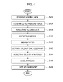
- FIG. 4 is a flow chart showing a process of performing an image process and a size measurement upon the 3D ultrasound image.
- the processing unit 130 is configured to synthesize the ultrasound data corresponding to the plurality of frames F i (1 ⁇ i ⁇ N) to form volume data 510 as shown in FIG. 5 , at step S402 in FIG. 4 .
- FIG. 5 is a schematic diagram showing an example of the volume data 510.
- the volume data 510 include a plurality of voxels (not shown) having brightness values.
- reference numerals 521, 522 and 523 represent an A plane, a B plane and a C plane, respectively.
- the A plane 521, the B plane 522 and the C plane 523 are mutually orthogonal.
- the axial direction is a Tx direction of the ultrasound signals
- the lateral direction is a longitudinal direction of the elements
- the elevation direction is a swing direction of the elements, i.e., a depth direction of the 3D ultrasound image.
- the processing unit 130 is configured to form the 2D ultrasound image based on the volume data 510, at step S404 in FIG. 4 .
- the 2D ultrasound image is displayed on a display unit 150 in FIG. 1 .
- the user sets the at least one seed point on the 2D ultrasound image displayed on the display unit 150 by using the user input unit 110.
- the 2D ultrasound image is an ultrasound image corresponding to the A plane 521, the B plane 522 or the C plane 523.
- the 2D ultrasound image may not be limited thereto.
- the processing unit 130 is configured to render the volume data 510 to form the 3D ultrasound image, at step S406 in FIG. 4 .
- the methods of rendering the volume data 510 are well known in the art. Thus, they have not been described in detail so as not to unnecessarily obscure the present invention.
- the processing unit 130 is configured to perform an edge detection of the objects of interest upon the 3D ultrasound image, at step S408 in FIG. 4 .
- the processing unit 130 performs the edge detection by using an edge mask such as Sobel, Prewitt, Robert, Canny and the like.
- the processing unit 130 performs the edge detection based on a difference of eigenvalues using a structure tensor.
- the processing unit 130 is configured to perform segmentation of the objects of interest upon the 3D ultrasound image based on the detected edges, at step S410 in FIG. 5 .
- the processing unit 130 further sets indexes on the segmented objects of interest.
- the index includes a text, a figure, etc.
- the processing unit 130 performs the segmentation of the objects of interest IO 1 , IO 2 and IO 3 upon the 3D ultrasound image UI based on the detected edges, as shown in FIG. 6 .
- the processing unit 130 further sets indexes OSG 1 , OSG 2 and OSG 3 on the segmented objects of interest IO 1 , IO 2 and IO 3 .
- the processing unit 130 sets a plurality of slices S 1 to S n on the 3D ultrasound image, as shown in FIG. 7 .
- the slices correspond to the frames F i (1 ⁇ i ⁇ N).
- the processing unit 130 further analyzes a first slice S 1 to detect edges VE 11 , VE 12 of the object of interest (i.e., a blood vessel) from the first slice S 1 .
- the processing unit 130 further analyzes a second slice S 2 to detect edges VE 21 , VE 22 of the object of interest from the second slice S 2 .
- the processing unit 130 further compares the edge VE 21 of the second slice S 2 with the edge VE 11 of the first slice S 1 to calculate location difference between the edges VE 21 and VE 11 , as shown in FIG. 8 .
- the processing unit 130 further compares the edge VE 22 of the second slice S 2 with the edge VE 12 of the first slice S 1 to calculate location difference between the edges VE 22 and VE 12 , as shown in FIG. 8 .
- the processing unit 130 further compares the edge VE 22 of the second slice S 2 with the edge VE 11 of the first slice S 1 to calculate location difference between the edges VE 22 and VE 11 , as shown in FIG. 8 .
- the processing unit 130 further compares the edge VE 21 of the second slice S 2 with the edge VE 12 of the first slice S 1 to calculate location difference between the edges VE 21 and VE 12 , as shown in FIG. 8 .
- the processing unit 130 further compares each of the calculated location differences with a predetermined threshold value. If it is determined that the location difference between the edges VE 21 and VE 11 and the location difference between the edges VE 22 and VE 12 are equal to or less than the threshold value, and the location difference between the edges VE 22 and VE 11 and the location difference between the edges VE 21 and VE 12 are more than the threshold value, then the processing unit 130 further connects the edge VE 21 to the edge VE 11 , and connect the edge VE 22 to the edge VE 12, as shown in FIG.
- the processing unit 130 performs the segmentation upon a third slice S 3 and a fourth slice S 4 as mentioned above.
- the processing unit 130 further analyzes a fifth slice S 5 to detect an edge VE 5 from the fifth slice S 5 .
- the processing unit 130 further compares the edge VE 5 of the fifth slice S 5 with an edge VE 41 of the fourth slice S 4 to calculate location difference between the edges VE 5 and VE 41 .
- the processing unit 130 further compares the edge VE 5 with an edge VE 42 of the fourth slice S 4 to calculate location difference between the edges VE 5 and VE 42 .
- the processing unit 130 further compares the calculated location differences with the threshold value.
- the processing unit 130 further connects the edge VE 5 to the edges VE 41 and VE 42 .
- the processing unit 130 further analyzes a sixth slice S 6 to detect edge VE 6 from the sixth slice S 6 .
- the processing unit 130 further compares the edge VE 6 of the fifth slice S 6 with the edge VE 5 of the fifth slice S 5 to calculate location difference between the edges VE 6 and VE 5 .
- the processing unit 130 further compares the calculated location difference with the threshold value.
- the processing unit 130 further connects the edge VE 6 to the edge VE 5 .
- the processing unit 130 further performs the segmentation of the object of interest upon a seventh slice S 7 to an n th slice S n as mentioned above.
- the processing unit 130 further analyzes the plurality of slices S 1 to S n to detect a vascular bifurcation VB of the object of interest as shown in FIG. 10 .
- the processing unit 130 further sets indexes VSG 1 , VSG 2 and VSG 3 on the segmented object of interest based on the vascular bifurcation VB.
- the processing unit 130 is configured to set the at least one seed point corresponding to the input information on the 3D ultrasound image, at step S412 in FIG. 4 .
- the processing unit 130 is configured to set the at least one seed point based on geometrical information of the 2D ultrasound image for the 3D ultrasound image.
- the processing unit 130 is configured to detect at least one object of interest corresponding to the at least one seed point set on the 3D ultrasound image, at step S414 in FIG. 4 .
- the processing unit 130 is configured to perform the image process of the detected object of upon the 3D ultrasound image, at step S416 in FIG. 4 .
- the processing unit 130 is configured to perform the image process for applying different colors to the detected object of interest upon the 3D ultrasound image.
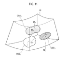
- the processing unit 130 performs the image process for applying different colors to the detected objects of interest IO 1 and IO 3 corresponding to seed points SP 1 and SP 2 , respectively, upon the 3D ultrasound image UI, as shown in FIG. 11 .
- the processing unit 130 is configured to perform the size measurement of the detected object of interest upon the 3D ultrasound image to form measurement information, at step S418 in FIG. 4 .
- the methods of the size measurement are well known in the art. Thus, they have not been described in detail so as not to unnecessarily obscure the present invention.
- the ultrasound system 100 further includes a storage unit 140.
- the storage unit 140 stores the ultrasound data acquired by the ultrasound data acquisition unit 120.
- the storage unit 140 further stores the volume data 510 formed by the processing unit 130.
- the ultrasound system 100 further includes the display unit 150.
- the display unit 150 displays the 2D ultrasound image and the 3D ultrasound image formed by the processing unit 130.
- the display unit 150 further displays the measurement information formed by the processing unit 130.
Landscapes
- Health & Medical Sciences (AREA)
- Life Sciences & Earth Sciences (AREA)
- Engineering & Computer Science (AREA)
- Physics & Mathematics (AREA)
- Medical Informatics (AREA)
- Animal Behavior & Ethology (AREA)
- Radiology & Medical Imaging (AREA)
- Nuclear Medicine, Radiotherapy & Molecular Imaging (AREA)
- Biomedical Technology (AREA)
- Heart & Thoracic Surgery (AREA)
- Biophysics (AREA)
- Molecular Biology (AREA)
- Surgery (AREA)
- Pathology (AREA)
- General Health & Medical Sciences (AREA)
- Public Health (AREA)
- Veterinary Medicine (AREA)
- Computer Vision & Pattern Recognition (AREA)
- General Physics & Mathematics (AREA)
- Theoretical Computer Science (AREA)
- Ultra Sonic Daignosis Equipment (AREA)
- Image Analysis (AREA)
- Image Processing (AREA)
Abstract
Embodiments for performing an image process and a size measurement upon a three-dimensional ultrasound image are disclosed. In one embodiment, by way of non-limiting example, an ultrasound system comprises: a user input unit configured to receive input information for setting at least one seed point on a two-dimensional ultrasound image from a user; an ultrasound data acquisition unit configured to transmit and receive ultrasound signals to and from a target object including a plurality of objects of interest and output ultrasound data; and a processing unit in communication with the user input unit and the ultrasound data acquisition unit, the processing unit being configured to form volume data based on the ultrasound data, form the two-dimensional ultrasound image and a three-dimensional ultrasound image based on volume data, detect at least one object of interest corresponding to the input information from the three-dimensional ultrasound image, and perform an image process and a size measurement of the detected object of interest upon the three-dimensional ultrasound image.
Description
- The present application claims priority from Korean Patent Application No.
10-2010-0006722 filed on January 26, 2010 - The present disclosure generally relates to ultrasound systems, and more particularly to performing an image process and size measurement upon a three-dimensional (3D) ultrasound image in an ultrasound system.
- An ultrasound system has become an important and popular diagnostic tool since it has a wide range of applications. Specifically, due to its non-invasive and non-destructive nature, the ultrasound system has been extensively used in the medical profession. Modem high-performance ultrasound systems and techniques are commonly used to produce two-dimensional (2D) or three-dimensional (3D) ultrasound images of internal features of an object (e.g., human organs).
- The ultrasound system may provide the 3D ultrasound image including clinical information such as spatial information and anatomical figures of the target object, which cannot be provided by the 2D ultrasound image. The ultrasound system may transmit ultrasound signals into a target object and receive ultrasound echo signals reflected from the target object. The ultrasound system may further form volume data based on the ultrasound echo signals. The ultrasound system may further render the volume data to thereby form the 3D ultrasound image.
- The ultrasound system may provide the 3D ultrasound image and the 2D ultrasound image corresponding to an A plane, a B plane and a C plane, which may be mutually orthogonal. However, there is a problem in that it is difficult to estimate how the objects of interest shown in the 2D ultrasound image are three-dimensionally indicated and what sizes the objects of interest have in the 3D ultrasound image.
- Embodiments for providing a plurality of slice images in an ultrasound system are disclosed herein. In one embodiment, by way of non-limiting example, an ultrasound system comprises: a user input unit configured to receive input information for setting at least one seed point on a two-dimensional ultrasound image from a user; an ultrasound data acquisition unit configured to transmit and receive ultrasound signals to and from a target object including a plurality of objects of interest and output ultrasound data; and a processing unit in communication with the user input unit and the ultrasound data acquisition unit, the processing unit being configured to form volume data based on the ultrasound data, form the two-dimensional ultrasound image and a three-dimensional ultrasound image based on volume data, detect at least one object of interest corresponding to the input information from the three-dimensional ultrasound image, and perform an image process and a size measurement of the detected object of interest upon the three-dimensional ultrasound image.
- In another embodiment, there is provided a method of performing an image process and a size measurement upon a three-dimensional ultrasound image, comprising: a) transmitting and receiving ultrasound signals to and from a target object including a plurality of objects of interest and output ultrasound data; b) forming volume data based on the ultrasound data; c) forming a two-dimensional ultrasound image and a three-dimensional ultrasound image based on the volume data; d) receiving input information for setting at least one seed point on the two-dimensional ultrasound image; e) detecting at least one object of interest corresponding to the input information from the three-dimensional ultrasound image; and f) performing an image process and a size measurement of the detected object of interest upon the three-dimensional ultrasound image.
- The Summary is provided to introduce a selection of concepts in a simplified form that are further described below in the Detailed Description. This Summary is not intended to identify key or essential features of the claimed subject matter, nor is it intended to be used in determining the scope of the claimed subject matter.
-
- FIG. 1
- is a block diagram showing an illustrative embodiment of an ultrasound system.
- FIG. 2
- is a block diagram showing an illustrative embodiment of an ultrasound data acquisition unit.
- FIG. 3
- is a schematic diagram showing an example of acquiring ultrasound data corresponding to a plurality of frames.
- FIG. 4
- is a flow chart showing a process of performing an image process and a size measurement upon a three-dimensional (3D) ultrasound image.
- FIG. 5
- is a schµematic diagram showing an example of volume data.
- FIG. 6
- is a schematic diagram showing an example of the 3D ultrasound image, a plurality of objects of interest and indexes.
- FIG. 7
- is a schematic diagram showing an example of a plurality of slices and an object of interest (blood vessel).
- FIG. 8
- is a schematic diagram showing an example of location difference between edges of the object of interest (blood vessel) on adjacent slices.
- FIG. 9
- is a schematic diagram showing an example of performing a segmentation of the object of interest (blood vessel).
- FIG. 10
- is a schematic diagram showing an example of the object of interest (blood vessel) and indexes.
- FIG. 11
- is a schematic diagram showing an example of performing the image process upon the 3D ultrasound image.
- A detailed description may be provided with reference to the accompanying drawings. One of ordinary skill in the art may realize that the following description is illustrative only and is not in any way limiting.
- Referring to
FIG. 1 , anultrasound system 100 in accordance with an illustrative embodiment is shown. As depicted therein, theultrasound system 100 includes auser input unit 110. Theuser input unit 110 is configured to receive input information for setting at least one seed point on a two-dimensional (2D) ultrasound image. Theuser input unit 110 includes a control panel, a mouse or a keyboard. However, it should be noted herein that theuser input unit 110 may not be limited thereto. - The
ultrasound system 100 further includes an ultrasounddata acquisition unit 120. The ultrasounddata acquisition unit 120 is configured to transmit and receive ultrasound signals to and from a target object and output ultrasound data. The target object includes a plurality of objects of interest (e.g., blood vessels, a heart, etc.). -
FIG. 2 is a block diagram showing an illustrative embodiment of the ultrasounddata acquisition unit 120. Referring toFIG. 2 , the ultrasounddata acquisition unit 120 includes a transmit (Tx) signal generatingsection 210, anultrasound probe 220, a beam former 230 and an ultrasounddata forming section 240. - The Tx
signal generating section 210 is configured to generate Tx signals. In one embodiment, the Txsignal generating section 210 generates Tx signals for obtaining a plurality of frames Fi ( 1≤ i ≤ N) corresponding to a three-dimensional (3D) ultrasound image at every predetermined time, as shown inFIG. 3 . -
FIG. 3 is a schematic diagram showing an example of acquiring ultrasound data corresponding to the plurality of frames Fi (1≤ i ≤ N). The plurality of frames Fi (1≤ i ≤ N) represents sectional planes of the target object (not shown). - Referring back to
FIG. 2 , theultrasound probe 220 includes a plurality of elements (not shown) for reciprocally converting between ultrasound signals and electrical signals. Theultrasound probe 220 is configured to transmit ultrasound signals to the target object in response to the Tx signals provided from the Txsignal generating section 210. Theultrasound probe 220 further receives ultrasound signals (i.e., ultrasound echo signals) from the target object and output the received signals. The received signals are analog signals. Theultrasound probe 220 includes a three-dimensional (3D) mechanical probe or a two-dimensional (2D) array probe. However, it should be noted herein that theultrasound probe 220 may not be limited thereto. - The beam former 230 is configured to convert the received signals provided from the
ultrasound probe 220 into digital signals. The beam former 230 further applies delays to the digital signals in consideration of the elements and focal points to output digital receive-focused signals. - The ultrasound
data forming section 240 is configured to form ultrasound data corresponding to the frames Fi (1≤ i ≤ N) based on the digital receive-focused signals provided from the beam former 230. The ultrasounddata forming section 240 further performs various signal processing (e.g., gain adjustment) upon the digital receive-focused signals. - Referring back to
FIG. 1 , theultrasound system 100 further includes aprocessing unit 130 in communication with theuser input unit 110 and the ultrasounddata acquisition unit 120. Theprocessing unit 130 includes a central processing unit, a microprocessor or a graphic processing unit. However, it should be noted herein that theprocessing unit 130 may not be limited thereto. -
FIG. 4 is a flow chart showing a process of performing an image process and a size measurement upon the 3D ultrasound image. Theprocessing unit 130 is configured to synthesize the ultrasound data corresponding to the plurality of frames Fi (1≤ i≤ N) to formvolume data 510 as shown inFIG. 5 , at step S402 inFIG. 4 . -
FIG. 5 is a schematic diagram showing an example of thevolume data 510. Thevolume data 510 include a plurality of voxels (not shown) having brightness values. InFIG. 5 ,reference numerals A plane 521, theB plane 522 and theC plane 523 are mutually orthogonal. Also, inFIG. 5 , the axial direction is a Tx direction of the ultrasound signals, the lateral direction is a longitudinal direction of the elements, and the elevation direction is a swing direction of the elements, i.e., a depth direction of the 3D ultrasound image. - The
processing unit 130 is configured to form the 2D ultrasound image based on thevolume data 510, at step S404 inFIG. 4 . The 2D ultrasound image is displayed on adisplay unit 150 inFIG. 1 . Thus, the user sets the at least one seed point on the 2D ultrasound image displayed on thedisplay unit 150 by using theuser input unit 110. In one embodiment, the 2D ultrasound image is an ultrasound image corresponding to theA plane 521, theB plane 522 or theC plane 523. However, it should be noted herein that the 2D ultrasound image may not be limited thereto. - The
processing unit 130 is configured to render thevolume data 510 to form the 3D ultrasound image, at step S406 inFIG. 4 . The methods of rendering thevolume data 510 are well known in the art. Thus, they have not been described in detail so as not to unnecessarily obscure the present invention. - The
processing unit 130 is configured to perform an edge detection of the objects of interest upon the 3D ultrasound image, at step S408 inFIG. 4 . In one embodiment, theprocessing unit 130 performs the edge detection by using an edge mask such as Sobel, Prewitt, Robert, Canny and the like. In another embodiment, theprocessing unit 130 performs the edge detection based on a difference of eigenvalues using a structure tensor. - The
processing unit 130 is configured to perform segmentation of the objects of interest upon the 3D ultrasound image based on the detected edges, at step S410 inFIG. 5 . Optionally, theprocessing unit 130 further sets indexes on the segmented objects of interest. The index includes a text, a figure, etc. - In one embodiment, the
processing unit 130 performs the segmentation of the objects of interest IO1, IO2 and IO3 upon the 3D ultrasound image UI based on the detected edges, as shown inFIG. 6 . Theprocessing unit 130 further sets indexes OSG1, OSG2 and OSG3 on the segmented objects of interest IO1, IO2 and IO3. - In another embodiment, the
processing unit 130 sets a plurality of slices S1 to Sn on the 3D ultrasound image, as shown inFIG. 7 . The slices correspond to the frames Fi (1≤ i ≤ N). However, it should be noted herein that the slices may not be limited thereto. Theprocessing unit 130 further analyzes a first slice S1 to detect edges VE11, VE12 of the object of interest (i.e., a blood vessel) from the first slice S1. Theprocessing unit 130 further analyzes a second slice S2 to detect edges VE21, VE22 of the object of interest from the second slice S2. Theprocessing unit 130 further compares the edge VE21 of the second slice S2 with the edge VE11 of the first slice S1 to calculate location difference between the edges VE21 and VE11, as shown inFIG. 8 . Theprocessing unit 130 further compares the edge VE22 of the second slice S2 with the edge VE12 of the first slice S1 to calculate location difference between the edges VE22 and VE12, as shown inFIG. 8 . Theprocessing unit 130 further compares the edge VE22 of the second slice S2 with the edge VE11 of the first slice S1 to calculate location difference between the edges VE22 and VE11, as shown inFIG. 8 . Theprocessing unit 130 further compares the edge VE21 of the second slice S2 with the edge VE12 of the first slice S1 to calculate location difference between the edges VE21 and VE12, as shown inFIG. 8 . Theprocessing unit 130 further compares each of the calculated location differences with a predetermined threshold value. If it is determined that the location difference between the edges VE21 and VE11 and the location difference between the edges VE22 and VE12 are equal to or less than the threshold value, and the location difference between the edges VE22 and VE11 and the location difference between the edges VE21 and VE12 are more than the threshold value, then theprocessing unit 130 further connects the edge VE21 to the edge VE11, and connect the edge VE22 to the edge VE12, as shown inFIG. 9 . Theprocessing unit 130 performs the segmentation upon a third slice S3 and a fourth slice S4 as mentioned above. Theprocessing unit 130 further analyzes a fifth slice S5 to detect an edge VE5 from the fifth slice S5. Theprocessing unit 130 further compares the edge VE5 of the fifth slice S5 with an edge VE41 of the fourth slice S4 to calculate location difference between the edges VE5 and VE41. Theprocessing unit 130 further compares the edge VE5 with an edge VE42 of the fourth slice S4 to calculate location difference between the edges VE5 and VE42. Theprocessing unit 130 further compares the calculated location differences with the threshold value. If it is determined that the location difference between the edges VE5 and VE41 and the location difference between the edges VE5 and VE42 are equal to or less than the threshold value, then theprocessing unit 130 further connects the edge VE5 to the edges VE41 and VE42. Theprocessing unit 130 further analyzes a sixth slice S6 to detect edge VE6 from the sixth slice S6. Theprocessing unit 130 further compares the edge VE6 of the fifth slice S6 with the edge VE5 of the fifth slice S5 to calculate location difference between the edges VE6 and VE5. Theprocessing unit 130 further compares the calculated location difference with the threshold value. If it is determined that the location difference between the edges VE6 and VE5 is equal to or less than the threshold value, then theprocessing unit 130 further connects the edge VE6 to the edge VE5. Theprocessing unit 130 further performs the segmentation of the object of interest upon a seventh slice S7 to an nth slice Sn as mentioned above.
Theprocessing unit 130 further analyzes the plurality of slices S1 to Sn to detect a vascular bifurcation VB of the object of interest as shown inFIG. 10 . Theprocessing unit 130 further sets indexes VSG1, VSG2 and VSG3 on the segmented object of interest based on the vascular bifurcation VB. - The
processing unit 130 is configured to set the at least one seed point corresponding to the input information on the 3D ultrasound image, at step S412 inFIG. 4 . In one embodiment, theprocessing unit 130 is configured to set the at least one seed point based on geometrical information of the 2D ultrasound image for the 3D ultrasound image. - The
processing unit 130 is configured to detect at least one object of interest corresponding to the at least one seed point set on the 3D ultrasound image, at step S414 inFIG. 4 . - The
processing unit 130 is configured to perform the image process of the detected object of upon the 3D ultrasound image, at step S416 inFIG. 4 . In one embodiment, theprocessing unit 130 is configured to perform the image process for applying different colors to the detected object of interest upon the 3D ultrasound image. For example, theprocessing unit 130 performs the image process for applying different colors to the detected objects of interest IO1 and IO3 corresponding to seed points SP1 and SP2, respectively, upon the 3D ultrasound image UI, as shown inFIG. 11 . - The
processing unit 130 is configured to perform the size measurement of the detected object of interest upon the 3D ultrasound image to form measurement information, at step S418 inFIG. 4 . The methods of the size measurement are well known in the art. Thus, they have not been described in detail so as not to unnecessarily obscure the present invention. - Referring back to
FIG. 1 , theultrasound system 100 further includes astorage unit 140. Thestorage unit 140 stores the ultrasound data acquired by the ultrasounddata acquisition unit 120. Thestorage unit 140 further stores thevolume data 510 formed by theprocessing unit 130. - The
ultrasound system 100 further includes thedisplay unit 150. Thedisplay unit 150 displays the 2D ultrasound image and the 3D ultrasound image formed by theprocessing unit 130. Thedisplay unit 150 further displays the measurement information formed by theprocessing unit 130. - Although embodiments have been described with reference to a number of illustrative embodiments thereof, it should be understood that numerous other modifications and embodiments can be devised by those skilled in the art that will fall within the scope of the principles of this disclosure. More particularly, numerous variations and modifications are possible in the component parts and/or arrangements of the subject combination arrangement within the scope of the disclosure, the drawings and the appended claims. In addition to variations and modifications in the component parts and/or arrangements, alternative uses will also be apparent to those skilled in the art.
Claims (8)
- An ultrasound system, comprising:a user input unit configured to receive input information for setting at least one seed point on a two-dimensional ultrasound image from a user;an ultrasound data acquisition unit configured to transmit and receive ultrasound signals to and from a target object including a plurality of objects of interest and output ultrasound data; anda processing unit in communication with the user input unit and the ultrasound data acquisition unit, the processing unit being configured to form volume data based on the ultrasound data, form the two-dimensional ultrasound image anda three-dimensional ultrasound image based on volume data, detect at least one object of interest corresponding to the input information from the three-dimensional ultrasound image, and perform an image process and a size measurement of the detected object of interest upon the three-dimensional ultrasound image.
- The ultrasound system of Claim 1, wherein the processing unit is configured to:perform an edge detection of the objects of interest upon the 3D ultrasound image;perform a segmentation of the objects of interest upon the 3D ultrasound image based on the detected edges;set the at least one seed point corresponding to the input information on the 3D ultrasound image; anddetect the at least one object of interest corresponding to the at least one seed point from the three-dimensional ultrasound image.
- The ultrasound system of Claim 1, wherein the processing unit is configured to detect the least one object of interest from the three-dimensional ultrasound image based on geometric information of the two-dimensional ultrasound image for the three-dimensional ultrasound image.
- The ultrasound system of Claim 1, wherein the processing unit is configured to perform the image process for applying different colors to the detected object of interest upon the three-dimensional ultrasound image.
- A method of performing an image process and a size measurement upon a three-dimensional ultrasound image, comprising:a) transmitting and receiving ultrasound signals to and from a target object including a plurality of objects of interest and output ultrasound data;b) forming volume data based on the ultrasound data;c) forming a two-dimensional ultrasound image and a three-dimensional ultrasound image based on the volume data;d) receiving input information for setting at least one seed point on the two-dimensional ultrasound image;e) detecting at least one object of interest corresponding to the input information from the three-dimensional ultrasound image; andf) performing an image process and a size measurement of the detected object of interest upon the three-dimensional ultrasound image.
- The method of Claim 5, wherein the step e) comprises:e1) performing edge detection of the objects of interest upon the three-dimensional ultrasound image;e2) performing segmentation of the objects of interest upon the three-dimensional ultrasound image based on the detected edges;e3) setting the at least one seed point corresponding to the input information on the three-dimensional ultrasound image; ande4) detecting the at least one object of interest corresponding to the at least one seed point from the three-dimensional ultrasound image.
- The method of Claim 6, wherein the step e4) comprises:detecting the at least one object of interest from the three-dimensional ultrasound image based on geometric information of the two-dimensional ultrasound image for the three-dimensional ultrasound image.
- The method of Claim 5, wherein the step f) comprises:performing the image process for applying different colors to the detected object of interest upon the three-dimensional ultrasound image.
Applications Claiming Priority (1)
| Application Number | Priority Date | Filing Date | Title |
|---|---|---|---|
| KR1020100006722A KR101175426B1 (en) | 2010-01-26 | 2010-01-26 | Ultrasound system and method for providing three-dimensional ultrasound image |
Publications (1)
| Publication Number | Publication Date |
|---|---|
| EP2347714A1 true EP2347714A1 (en) | 2011-07-27 |
Family
ID=44012596
Family Applications (1)
| Application Number | Title | Priority Date | Filing Date |
|---|---|---|---|
| EP11151476A Withdrawn EP2347714A1 (en) | 2010-01-26 | 2011-01-20 | Performing image process and size measurement upon a three-dimensional ultrasound image in an ultrasound system |
Country Status (4)
| Country | Link |
|---|---|
| US (1) | US8900147B2 (en) |
| EP (1) | EP2347714A1 (en) |
| JP (1) | JP2011152416A (en) |
| KR (1) | KR101175426B1 (en) |
Cited By (2)
| Publication number | Priority date | Publication date | Assignee | Title |
|---|---|---|---|---|
| CN107766874A (en) * | 2017-09-07 | 2018-03-06 | 沈燕红 | A kind of measuring method and measuring system of ultrasound volume biological parameter |
| CN112529770A (en) * | 2020-12-07 | 2021-03-19 | 维沃移动通信有限公司 | Image processing method, image processing device, electronic equipment and readable storage medium |
Families Citing this family (9)
| Publication number | Priority date | Publication date | Assignee | Title |
|---|---|---|---|---|
| RU2620865C2 (en) | 2012-06-25 | 2017-05-30 | Конинклейке Филипс Н.В. | System and method for three-dimensional ultrasound measuring volumetric areas |
| KR101468419B1 (en) | 2012-12-04 | 2014-12-03 | 삼성메디슨 주식회사 | Medical system and method for providing measurement information using three-dimensional calliper |
| US9149260B2 (en) | 2014-02-28 | 2015-10-06 | 3DBiopsy LLC | Biopsy needle assembly |
| KR102347038B1 (en) | 2014-11-06 | 2022-01-04 | 삼성메디슨 주식회사 | Ultra sonic apparatus and method for scanning thereof |
| CN104851108B (en) * | 2015-06-09 | 2017-11-28 | 武汉联影医疗科技有限公司 | Arteria hepatica dividing method based on CT images |
| GB2559013B (en) | 2014-12-02 | 2019-07-17 | Shanghai United Imaging Healthcare Co Ltd | A method and system for image processing |
| JP6580013B2 (en) * | 2016-09-29 | 2019-09-25 | 株式会社日立製作所 | Image processing apparatus and method |
| WO2019078577A1 (en) * | 2017-10-16 | 2019-04-25 | Samsung Medison Co., Ltd. | Methods and systems for assessing ovarian parameters from ultrasound images |
| WO2019232742A1 (en) * | 2018-06-07 | 2019-12-12 | 深圳迈瑞生物医疗电子股份有限公司 | Image analysis method based on ultrasonic imaging device, and ultrasonic imaging device |
Citations (7)
| Publication number | Priority date | Publication date | Assignee | Title |
|---|---|---|---|---|
| US20030152262A1 (en) * | 2002-02-11 | 2003-08-14 | Fei Mao | Method and system for recognizing and selecting a region of interest in an image |
| US6694163B1 (en) * | 1994-10-27 | 2004-02-17 | Wake Forest University Health Sciences | Method and system for producing interactive, three-dimensional renderings of selected body organs having hollow lumens to enable simulated movement through the lumen |
| US20070133852A1 (en) * | 2005-11-23 | 2007-06-14 | Jeffrey Collins | Method and system of computer-aided quantitative and qualitative analysis of medical images |
| EP1892671A2 (en) * | 2006-08-23 | 2008-02-27 | Medison Co., Ltd. | System and method for determining the volume of an object by image processing |
| US20080118118A1 (en) * | 2006-11-22 | 2008-05-22 | Ralf Berger | Method and Apparatus for Segmenting Images |
| US20080292169A1 (en) * | 2007-05-21 | 2008-11-27 | Cornell University | Method for segmenting objects in images |
| EP2098993A1 (en) * | 2008-03-05 | 2009-09-09 | Medison Co., Ltd. | Volume measurement in an ultrasound system |
Family Cites Families (6)
| Publication number | Priority date | Publication date | Assignee | Title |
|---|---|---|---|---|
| JP3047265B2 (en) | 1991-11-25 | 2000-05-29 | 株式会社日立メディコ | Three-dimensional image creation method for ultrasonic diagnostic equipment |
| JP4068234B2 (en) * | 1998-10-05 | 2008-03-26 | 株式会社東芝 | Ultrasonic diagnostic equipment |
| US7158692B2 (en) * | 2001-10-15 | 2007-01-02 | Insightful Corporation | System and method for mining quantitive information from medical images |
| KR100954989B1 (en) | 2006-10-18 | 2010-04-30 | 주식회사 메디슨 | Ultrasound diagnostic apparatus and method for measuring the size of an object |
| KR101028354B1 (en) | 2007-03-20 | 2011-06-14 | 주식회사 메디슨 | Ultrasound System and Method for Forming Ultrasound Images |
| JP5414157B2 (en) | 2007-06-06 | 2014-02-12 | 株式会社東芝 | Ultrasonic diagnostic apparatus, ultrasonic image processing apparatus, and ultrasonic image processing program |
-
2010
- 2010-01-26 KR KR1020100006722A patent/KR101175426B1/en active Active
-
2011
- 2011-01-20 EP EP11151476A patent/EP2347714A1/en not_active Withdrawn
- 2011-01-24 JP JP2011012258A patent/JP2011152416A/en active Pending
- 2011-01-25 US US13/013,306 patent/US8900147B2/en active Active
Patent Citations (7)
| Publication number | Priority date | Publication date | Assignee | Title |
|---|---|---|---|---|
| US6694163B1 (en) * | 1994-10-27 | 2004-02-17 | Wake Forest University Health Sciences | Method and system for producing interactive, three-dimensional renderings of selected body organs having hollow lumens to enable simulated movement through the lumen |
| US20030152262A1 (en) * | 2002-02-11 | 2003-08-14 | Fei Mao | Method and system for recognizing and selecting a region of interest in an image |
| US20070133852A1 (en) * | 2005-11-23 | 2007-06-14 | Jeffrey Collins | Method and system of computer-aided quantitative and qualitative analysis of medical images |
| EP1892671A2 (en) * | 2006-08-23 | 2008-02-27 | Medison Co., Ltd. | System and method for determining the volume of an object by image processing |
| US20080118118A1 (en) * | 2006-11-22 | 2008-05-22 | Ralf Berger | Method and Apparatus for Segmenting Images |
| US20080292169A1 (en) * | 2007-05-21 | 2008-11-27 | Cornell University | Method for segmenting objects in images |
| EP2098993A1 (en) * | 2008-03-05 | 2009-09-09 | Medison Co., Ltd. | Volume measurement in an ultrasound system |
Cited By (3)
| Publication number | Priority date | Publication date | Assignee | Title |
|---|---|---|---|---|
| CN107766874A (en) * | 2017-09-07 | 2018-03-06 | 沈燕红 | A kind of measuring method and measuring system of ultrasound volume biological parameter |
| CN112529770A (en) * | 2020-12-07 | 2021-03-19 | 维沃移动通信有限公司 | Image processing method, image processing device, electronic equipment and readable storage medium |
| CN112529770B (en) * | 2020-12-07 | 2024-01-26 | 维沃移动通信有限公司 | Image processing methods, devices, electronic equipment and readable storage media |
Also Published As
| Publication number | Publication date |
|---|---|
| KR20110087355A (en) | 2011-08-03 |
| US8900147B2 (en) | 2014-12-02 |
| JP2011152416A (en) | 2011-08-11 |
| US20110184290A1 (en) | 2011-07-28 |
| KR101175426B1 (en) | 2012-08-20 |
Similar Documents
| Publication | Publication Date | Title |
|---|---|---|
| US8900147B2 (en) | Performing image process and size measurement upon a three-dimensional ultrasound image in an ultrasound system | |
| EP2511878B1 (en) | Providing three-dimensional ultrasound image based on three-dimensional color reference table in ultrasound system | |
| US9220441B2 (en) | Medical system and method for providing measurement information using three-dimensional caliper | |
| EP2333576A2 (en) | Providing a three-dimensional ultrasound image based on a sub region of interest in an ultrasound system | |
| EP2289420B1 (en) | Setting an optimal image parameter in an ultrasound system | |
| EP2302414A2 (en) | Ultrasound system and method of performing measurement on three-dimensional ultrasound image | |
| US9069062B2 (en) | Surface rendering for volume data in an ultrasound system | |
| US8956298B2 (en) | Providing an ultrasound spatial compound image in an ultrasound system | |
| EP2444001A1 (en) | Providing an ultrasound spatial compound image based on a phased array probe in an ultrasound system | |
| KR100893286B1 (en) | Image processing system and method | |
| US9649095B2 (en) | 3-dimensional ultrasound image provision using volume slices in an ultrasound system | |
| EP2444821A2 (en) | Providing an ultrasound spatial compound image based on center lines of ultrasound images in an ultrasound system | |
| EP2249178B1 (en) | Arranging a three-dimensional ultrasound image in an ultrasound system | |
| EP2281509B1 (en) | Setting a Sagittal View in an Ultrasound System | |
| EP2446827B1 (en) | Providing a body mark in an ultrasound system | |
| EP2966468A1 (en) | Providing at least one slice image based on at least three points in an ultrasound system | |
| EP2425784A1 (en) | Providing a color Doppler mode image in an ultrasound system | |
| EP2281510A1 (en) | Providing a plurality of slice images in an ultrasound system | |
| EP2453255A1 (en) | Ultrasound system and method for providing preview image | |
| EP2386251A1 (en) | Providing at least one slice image with additional information in an ultrasound system | |
| EP2422704A2 (en) | Providing ultrasound spatial compound images in an ultrasound system | |
| US20100152585A1 (en) | Ultrasound System And Method For Forming A Plurality Of Three-Dimensional Ultrasound Images | |
| US9131918B2 (en) | 3-dimensional ultrasound image provision using volume slices in an ultrasound system | |
| EP2740409A1 (en) | Medical system, medical imaging apparatus, and method of providing three-dimensional marker | |
| KR20140066578A (en) | Ultrasound system and method of providing navigator for guiding position of plane |
Legal Events
| Date | Code | Title | Description |
|---|---|---|---|
| PUAI | Public reference made under article 153(3) epc to a published international application that has entered the european phase |
Free format text: ORIGINAL CODE: 0009012 |
|
| AK | Designated contracting states |
Kind code of ref document: A1 Designated state(s): AL AT BE BG CH CY CZ DE DK EE ES FI FR GB GR HR HU IE IS IT LI LT LU LV MC MK MT NL NO PL PT RO RS SE SI SK SM TR |
|
| AX | Request for extension of the european patent |
Extension state: BA ME |
|
| RIN1 | Information on inventor provided before grant (corrected) |
Inventor name: YANG, EUN HO Inventor name: YOO, JAE HEUNG |
|
| STAA | Information on the status of an ep patent application or granted ep patent |
Free format text: STATUS: THE APPLICATION HAS BEEN WITHDRAWN |
|
| 18W | Application withdrawn |
Effective date: 20120202 |