EP2347538B1 - Method and apparatus for generating a preamble for use in cable transmission systems - Google Patents
Method and apparatus for generating a preamble for use in cable transmission systems Download PDFInfo
- Publication number
- EP2347538B1 EP2347538B1 EP09752234.6A EP09752234A EP2347538B1 EP 2347538 B1 EP2347538 B1 EP 2347538B1 EP 09752234 A EP09752234 A EP 09752234A EP 2347538 B1 EP2347538 B1 EP 2347538B1
- Authority
- EP
- European Patent Office
- Prior art keywords
- carriers
- preamble
- beginning
- subsequent
- even numbered
- Prior art date
- Legal status (The legal status is an assumption and is not a legal conclusion. Google has not performed a legal analysis and makes no representation as to the accuracy of the status listed.)
- Active
Links
- 238000000034 method Methods 0.000 title claims description 41
- 230000005540 biological transmission Effects 0.000 title claims description 12
- 239000000969 carrier Substances 0.000 claims description 62
- 230000011664 signaling Effects 0.000 claims description 35
- 230000000295 complement effect Effects 0.000 claims description 31
- 238000012937 correction Methods 0.000 claims description 11
- 238000001228 spectrum Methods 0.000 claims description 10
- 238000013507 mapping Methods 0.000 claims description 7
- 238000012545 processing Methods 0.000 claims description 5
- 125000004122 cyclic group Chemical group 0.000 claims description 4
- 230000008569 process Effects 0.000 claims description 4
- 230000001131 transforming effect Effects 0.000 claims 2
- 230000006870 function Effects 0.000 description 11
- 238000010586 diagram Methods 0.000 description 7
- 230000008901 benefit Effects 0.000 description 4
- 238000013461 design Methods 0.000 description 4
- 238000005516 engineering process Methods 0.000 description 2
- 238000012986 modification Methods 0.000 description 2
- 230000004048 modification Effects 0.000 description 2
- 230000003044 adaptive effect Effects 0.000 description 1
- 238000004891 communication Methods 0.000 description 1
- 239000000470 constituent Substances 0.000 description 1
- 238000005314 correlation function Methods 0.000 description 1
- 238000013500 data storage Methods 0.000 description 1
- 230000003247 decreasing effect Effects 0.000 description 1
- 238000002592 echocardiography Methods 0.000 description 1
- 238000011156 evaluation Methods 0.000 description 1
- 230000006872 improvement Effects 0.000 description 1
- 238000003780 insertion Methods 0.000 description 1
- 230000037431 insertion Effects 0.000 description 1
- 230000003993 interaction Effects 0.000 description 1
- 230000002452 interceptive effect Effects 0.000 description 1
- 230000002093 peripheral effect Effects 0.000 description 1
- 238000007639 printing Methods 0.000 description 1
- 230000003595 spectral effect Effects 0.000 description 1
- 230000007704 transition Effects 0.000 description 1
Images


Classifications
-
- H—ELECTRICITY
- H04—ELECTRIC COMMUNICATION TECHNIQUE
- H04L—TRANSMISSION OF DIGITAL INFORMATION, e.g. TELEGRAPHIC COMMUNICATION
- H04L27/00—Modulated-carrier systems
- H04L27/26—Systems using multi-frequency codes
-
- H—ELECTRICITY
- H04—ELECTRIC COMMUNICATION TECHNIQUE
- H04L—TRANSMISSION OF DIGITAL INFORMATION, e.g. TELEGRAPHIC COMMUNICATION
- H04L27/00—Modulated-carrier systems
- H04L27/26—Systems using multi-frequency codes
- H04L27/2601—Multicarrier modulation systems
- H04L27/2602—Signal structure
- H04L27/2605—Symbol extensions, e.g. Zero Tail, Unique Word [UW]
-
- H—ELECTRICITY
- H03—ELECTRONIC CIRCUITRY
- H03M—CODING; DECODING; CODE CONVERSION IN GENERAL
- H03M13/00—Coding, decoding or code conversion, for error detection or error correction; Coding theory basic assumptions; Coding bounds; Error probability evaluation methods; Channel models; Simulation or testing of codes
-
- H—ELECTRICITY
- H04—ELECTRIC COMMUNICATION TECHNIQUE
- H04B—TRANSMISSION
- H04B3/00—Line transmission systems
- H04B3/02—Details
- H04B3/04—Control of transmission; Equalising
-
- H—ELECTRICITY
- H04—ELECTRIC COMMUNICATION TECHNIQUE
- H04L—TRANSMISSION OF DIGITAL INFORMATION, e.g. TELEGRAPHIC COMMUNICATION
- H04L5/00—Arrangements affording multiple use of the transmission path
- H04L5/003—Arrangements for allocating sub-channels of the transmission path
- H04L5/0048—Allocation of pilot signals, i.e. of signals known to the receiver
-
- H—ELECTRICITY
- H04—ELECTRIC COMMUNICATION TECHNIQUE
- H04L—TRANSMISSION OF DIGITAL INFORMATION, e.g. TELEGRAPHIC COMMUNICATION
- H04L5/00—Arrangements affording multiple use of the transmission path
- H04L5/003—Arrangements for allocating sub-channels of the transmission path
- H04L5/0053—Allocation of signaling, i.e. of overhead other than pilot signals
-
- H—ELECTRICITY
- H04—ELECTRIC COMMUNICATION TECHNIQUE
- H04L—TRANSMISSION OF DIGITAL INFORMATION, e.g. TELEGRAPHIC COMMUNICATION
- H04L1/00—Arrangements for detecting or preventing errors in the information received
- H04L1/0001—Systems modifying transmission characteristics according to link quality, e.g. power backoff
- H04L1/0006—Systems modifying transmission characteristics according to link quality, e.g. power backoff by adapting the transmission format
- H04L1/0007—Systems modifying transmission characteristics according to link quality, e.g. power backoff by adapting the transmission format by modifying the frame length
-
- H—ELECTRICITY
- H04—ELECTRIC COMMUNICATION TECHNIQUE
- H04L—TRANSMISSION OF DIGITAL INFORMATION, e.g. TELEGRAPHIC COMMUNICATION
- H04L1/00—Arrangements for detecting or preventing errors in the information received
- H04L1/004—Arrangements for detecting or preventing errors in the information received by using forward error control
- H04L1/0056—Systems characterized by the type of code used
- H04L1/0057—Block codes
-
- H—ELECTRICITY
- H04—ELECTRIC COMMUNICATION TECHNIQUE
- H04L—TRANSMISSION OF DIGITAL INFORMATION, e.g. TELEGRAPHIC COMMUNICATION
- H04L1/00—Arrangements for detecting or preventing errors in the information received
- H04L2001/0092—Error control systems characterised by the topology of the transmission link
- H04L2001/0093—Point-to-multipoint
Definitions
- the present principles relate to cable transmission systems and techniques. More particularly, it relates to a preamble design for the DVB-C2 standard used for cable channel transmissions.
- DVB-C2 next generation digital cable transmission system being developed by the DVB Project
- DVB-C2 shall reuse the content of DVB-T2 Standard as much as possible.
- OFDM technique will be adopted as well as the coding technique (BCH+LDPC) specified in DVB-T2 Standard.
- BCH+LDPC the coding technique
- DVB-T2 Standard is designed for using in the terrestrial wireless channel while the DVB-C2 Standard is designed for using in the cable channel.
- Cable channels differ from wireless channels in two aspects. First, cable channel is a high quality (high SNR) channel with only a few weak echoes. Second, the wireless spectrum assigned for TV broadcasting is confined by FCC while we can use the spectrum with high freedom in the cable networks. Consequently, the signal frame structure and preambles used in DVB-T2 may not be suitable to be reused in DVB-C2 Standard.
- DVB PROJECT " Frame structure channel coding and modulation for a second generation digital terrestrial television broadcasting system (DVB-T2)" INTERNET CITATION 29 August 2008, pages 1-158, retrieved from the Internet: URL:http://www.dvb.org/technology/dvbt2/a122.tm3980r5.
- DVB-T2.pdf discloses, amongst others, a scheme for modulation and error correction coding of the L1 data of DVB-T2, a frame structure of DVB-T2 where a T2 frame starts with a P1 preamble symbol, P1 symbol insertion, and pilot patterns.
- the present principles are directed to methods and an apparatus for Preamble design in DVB-C2 standard used in digital cable transmission environments.
- processor or “controller” should not be construed to refer exclusively to hardware capable of executing software, and may implicitly include, without limitation, digital signal processor (“DSP”) hardware, read-only memory (“ROM”) for storing software, random access memory (“RAM”), and non-volatile storage.
- DSP digital signal processor
- ROM read-only memory
- RAM random access memory
- any switches shown in the figures are conceptual only. Their function may be carried out through the operation of program logic, through dedicated logic, through the interaction of program control and dedicated logic, or even manually, the particular technique being selectable by the implementer as more specifically understood from the context.
- any element expressed as a means for performing a specified function is intended to encompass any way of performing that function including, for example, a) a combination of circuit elements that performs that function or b) software in any form, including, therefore, firmware, microcode or the like, combined with appropriate circuitry for executing that software to perform the function.
- the present principles as defined by such claims reside in the fact that the functionalities provided by the various recited means are combined and brought together in the manner which the claims call for.
- a preamble is designed for use in DVB-C2 Standard.
- the preamble of the present principles has multiple functions including frame timing synchronization, frequency offset estimation, system information signaling, and initial channel estimation.
- the preamble design of the present principles is motivated by the need for an efficient preamble structure for use in cable channels.
- the preamble structure of the present principles possesses the following functions:
- a DVB-C2 frame 10 consists of a bunch of OFDM symbols 12a - 12n and the first OFDM symbol is a preamble symbol 14 which is used to perform synchronization and signaling of C2 system.
- the FFT size of the OFDM modulation is selected as 4k.
- the preamble is designed using OFDM modulation with 4k carriers.
- Fig. 2a shows the block diagram of an exemplary method 20 of generating the preamble.
- a complementary sequence 22 is inserted in the beginning carriers as a header (see for example, Fig. 3 ) and then mapped 24 into modulation symbols (e.g., BPSK mapping).
- modulation symbols e.g., BPSK mapping
- the complementary sequence is part of the standard and can be referred to at Table 63 in the Draft ESTY EN 302 755 V1.1.1_0.2(2008-10).
- the mapped symbols are assigned to the allocated even carriers, thus the mapping occurs before the allocation of the even carriers.
- the signaling bits of system information 26 are protected by an error correction code 28 and then mapped into modulations symbols of either orthogonal codes or QAM symbols (30).
- Fig. 5 shows an example of a structure of the preamble symbols..
- pilot carriers can be used to perform channel estimation.
- Fig. 6 shows another example of using Walsh code of length 2 to convey 1 bit.
- the information bit 0 is transmitted by the code (1,1) and the information bit 1 is transmitted by the code (1,-1).
- the modulator allocates the system bit information and complementary sequence to the even carriers 32. It is important to note that the according to the preferred implementation of the present principles, only even carriers are used and the odd carriers are left as virtual carriers.
- the preamble signal is transformed to the time domain by IFFT operation 34 and depending on the desired implementation, a cyclic prefix (CP) may be added 36 to complete the generation of the DVB-C2 preamble.
- CP cyclic prefix
- Figure 2b shows the method steps 20b as derived from the block diagram of Figure 2a .
- the complementary sequence is inserted as a header in beginning carriers 22, the signaling bits are protected with error correction codes 28, and both the complementary sequence and signaling bits are mapped into modulation symbols (24, 30), and then they are allocated (32) to the even carriers only.
- Figure 2c shows another implementation of the method 20c according to the present principles.
- consideration is made for when two or more channels in the cable transmission are bonded (40).
- the added step of ensuring (44) the generated preamble repeated in frequency fills the complete spectrum of the bonded channels is also required.
- Figure 7 shows an apparatus 70 for generating the DVB-C2 preamble according to the present principles.
- a processor 72 in communication with a memory 74 and modulator 76 controls the preamble generation by utilizing the below criterion and performing the steps for the same.
- memory 74 can contain the variations in complementary sequences needed and the processor 72 will make determinations as to which complementary sequences are used during preamble generation so as to coordinate the same with the desired cable transmission application.
- the first and second criteria come up with the need to support Partial Reception in the receiver side when the Channel Bonding technique is applied in the transmitter side.
- the Channel Bonding technique By using the Channel Bonding technique, several channels are bonded together to provide a large spectrum. Thus, this large spectrum can be divided into subchannels or data slices according to the required bandwidth of individual service. To be more flexible, a subchannel or a data slice is allowed to start at any point (carrier) within the bonding spectrum. Then, the preamble has to be received and detected by a receiver at any tuning position within the bonding spectrum. It is worth noting that the guard band cannot be removed or reduced if Partial Reception is implemented in the receiver. Thus, the spectral efficiency does not have an apparent improvement when the Channel Bonding technique is used.
- the first two criteria can be released.
- the third criterion is made so that the preamble has a repetition structure in time domain to enable fast preamble identification. This kind of structure is also used in IEEE 802.11 and 802.16. The repetition structure can be easily understood. Consider that we modulate even carriers only and leave all odd carriers as virtual carriers.
- This structure can be used to perform frame timing synchronization and fractional frequency offset estimation.
- the guard interval can also achieve these two goals, the performance is degraded when the length of guard interval is not greatly larger than the channel length.
- the frequency offset can be separated as an integer part and a fractional part.
- the fractional part of frequency offset can be estimated by the time domain repetition structure.
- the estimation of integer part frequency offset has to rely on frequency domain pilots due to phase ambiguity problem for time domain signals.
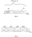
- a complementary sequence is allocated in the frequency domain as shown in Fig. 3 to assist integer frequency offset estimation.
- the length of the complementary sequence shall be selected according to the channel condition. There are 8 orthogonal complementary sequences of length 64 and 16 orthogonal complementary sequences of length 256, specified in DVB-T2 for the P1 preamble. Each of the complementary sequences of length 64 is made by a concatenation of a set of 8 complementary sequences of length 8.
- the 8 complementary sequences of length 64 are made by 8 orthogonal sets of complementary sequences.
- the complementary sequences of length 256 are made by the same way. They are made by 16 orthogonal sets of complementary sequences of length 16.
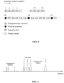
- one of the sequences with a length of 64 (124721741D482E7B in hexadecimal notation), is selected and allocated in the beginning of the preamble as shown in Fig. 5 and Fig. 6 .
- the complementary sequence is allocated in the even carriers of the first 128 carriers. Note that we use a complementary sequence instead of 8 orthogonal complementary sequences which can convey 3 bit information implemented in DVB-T2. The processing time to estimate the integer part of frequency offset is decreased by doing so.
- scattered pilot pattern PP5 is applied to the DVB-C2 system.
- the signaling bits are protected by BCH and LDPC codes and then mapped to QAM symbols in available even carriers. Signaling by this method can allow more information bits transmitted but the decoding complexity is larger than the signaling method described below.
- the rms delay spread ⁇ ⁇ is equal to 97.5 ns.
- the subcarrier spacing is approximately 2.232 kHz.
- the bits conveying system information should ideally be error free. Therefore, an error correction code added as shown in Fig. 2 .
- the selection of the orthogonal codes and error correction codes depends on the number of required system information bits and the implementation complexity.
- the Walsh Code of length 8 is selected here for DVB-C2 preamble.
- the mapping of bits to Walsh code is given in Table 1 below: TABLE 1 Bits Walsh Code 000 1,1,1,1,1,1,1 001 1,-1,1,-1,1,-1,1,-1 010 1,1,-1,-1,1,1,-1,-1 011 1,-1,-1,1,1,-1,-1,1 100 1,1,1,1,-1,-1,-1,-1 101 1,.-1,1,-1,-1,1,-1,1 110 1,1,-1,-1,-1,-1,1,1 111 1,-1,-1,1,-1,1,1,-1,-1
- K p is selected to be 3200.
- a Walsh code of length 8 is able to convey 3 bits of information. Therefore, 576 information coding bits are transmitted.
- the Reed-Muller Code RM(64,42,8) is selected to protect signaling bits of system information.
- the preamble can carry 378 signaling bits of system information.
- the total 576 bits are divided into 9 sets of 64 bits to carry 9 sets of 42 signaling bits of system information.
- the selection of the Reed-Muller code is due to its simplicity of decoding. If Walsh Code with length 4 and a more robust error correction code e.g., Reed-Solomon code are used, it is possible to carry more than 600 signaling bits. It is worth noting that by using this scheme to transmit signaling bits, no channel estimation is required in decoding signaling bits. Thus, the time delay is greatly reduced.
- the channel gain coefficients on those pilot carriers in the preamble can be reuse in the following OFDM symbols.
- the second signaling method after we decode the system information bits, we can encode the decoding bits to get the original bits and thus transmitted orthogonal codes. Then, the channel gain coefficients in those modulated subcarriers can be easily obtained. It is worth noting that we get a much larger number of channel gain coefficients than what we get using the first signaling method. Since the cable channel is a stable channel, the channel gain coefficients obtained from the preamble are very helpful for channel estimation. The C2 system will be benefited by this initial channel estimation.
- the teachings of the present principles are implemented as a combination of hardware and software.
- the software may be implemented as an application program tangibly embodied on a program storage unit.
- the application program may be uploaded to, and executed by, a machine comprising any suitable architecture.
- the machine is implemented on a computer platform having hardware such as one or more central processing units (“CPU"), a random access memory (“RAM”), and input/output ("I/O") interfaces.
- CPU central processing units
- RAM random access memory
- I/O input/output
- the computer platform may also include an operating system and microinstruction code.
- the various processes and functions described herein may be either part of the microinstruction code or part of the application program, or any combination thereof, which may be executed by a CPU.
- various other peripheral units may be connected to the computer platform such as an additional data storage unit and a printing unit.
Description
- The present principles relate to cable transmission systems and techniques. More particularly, it relates to a preamble design for the DVB-C2 standard used for cable channel transmissions.
- Recently, DVB-C2 (next generation digital cable transmission system being developed by the DVB Project) Standard is under progress. An agreement is made that DVB-C2 shall reuse the content of DVB-T2 Standard as much as possible. As a result, OFDM technique will be adopted as well as the coding technique (BCH+LDPC) specified in DVB-T2 Standard. However, it must be noted that DVB-T2 Standard is designed for using in the terrestrial wireless channel while the DVB-C2 Standard is designed for using in the cable channel. Cable channels differ from wireless channels in two aspects. First, cable channel is a high quality (high SNR) channel with only a few weak echoes. Second, the wireless spectrum assigned for TV broadcasting is confined by FCC while we can use the spectrum with high freedom in the cable networks. Consequently, the signal frame structure and preambles used in DVB-T2 may not be suitable to be reused in DVB-C2 Standard.
- The document
DVB PROJECT: "Frame structure channel coding and modulation for a second generation digital terrestrial television broadcasting system (DVB-T2)" INTERNET CITATION 29 August 2008, pages 1-158, retrieved from the Internet: URL:http://www.dvb.org/technology/dvbt2/a122.tm3980r5. DVB-T2.pdf
discloses, amongst others, a scheme for modulation and error correction coding of the L1 data of DVB-T2, a frame structure of DVB-T2 where a T2 frame starts with a P1 preamble symbol, P1 symbol insertion, and pilot patterns. - The conference publication
YUH-REN TSAI ET AL: "Adaptive Channel Estimation for MB-OFDM Systems in Multi-Access Interfering Environments" VEHICULAR TECHNOLOGY CONFERENCE, 2008. VTC SPRING 2008. IEEE, IEEE, PISCATAWAY, NJ, USA, 11 May 2008
presents work on the feasability of introducing time domain redundancy into OFDM preamble symbols. It is purported that, assuming that only the even-numbered subcarriers are used, the last half of the OFDM symbol in the time domain is the duplication of the first half. - The invention is defined by the appended claims. Any other reference to embodiments is to be understood as examples useful for understanding the invention.
- The present principles may be better understood in accordance with the following exemplary figures, in which:
-
Figure 1 is representation of the frame structure of DVB-C2 signals; -
Figures 2a-2c show block diagrams illustrating the method for generating a preamble according to various implementations of the present principles; -
Figure 3 is a representation of the composition of a DVB-C2 preamble in a frequency domain; -
Figure 4 is an example of a cyclic representation of the preamble with bonded channels according to an implementation of the present principles; -
Figure 5 is a representation of a structure of the preamble signals according to an implementation of the present principles; -
Figure 6 is an example of a preamble using Walsh codes according to an implementation of the present principles; and -
Figure 7 is a block diagram of an apparatus for implementing the preamble generation according to an embodiment of the present principles. - The present principles are directed to methods and an apparatus for Preamble design in DVB-C2 standard used in digital cable transmission environments.
- The present description illustrates the present principles. It will thus be appreciated that those skilled in the art will be able to devise various arrangements that, although not explicitly described or shown herein, embody the present principles and are included within its scope.
- All examples and conditional language recited herein are intended for pedagogical purposes to aid the reader in understanding the present principles and the concepts contributed by the inventor(s) to furthering the art, and are to be construed as being without limitation to such specifically recited examples and conditions.
- Thus, for example, it will be appreciated by those skilled in the art that the block diagrams presented herein represent conceptual views of illustrative circuitry embodying the present principles. Similarly, it will be appreciated that any flow charts, flow diagrams, state transition diagrams, pseudocode, and the like represent various processes which may be substantially represented in computer readable media and so executed by a computer or processor, whether or not such computer or processor is explicitly shown.
- The functions of the various elements shown in the figures may be provided through the use of dedicated hardware as well as hardware capable of executing software in association with appropriate software. When provided by a processor, the functions may be provided by a single dedicated processor, by a single shared processor, or by a plurality of individual processors, some of which may be shared. Moreover, explicit use of the term "processor" or "controller" should not be construed to refer exclusively to hardware capable of executing software, and may implicitly include, without limitation, digital signal processor ("DSP") hardware, read-only memory ("ROM") for storing software, random access memory ("RAM"), and non-volatile storage.
- Other hardware, conventional and/or custom, may also be included. Similarly, any switches shown in the figures are conceptual only. Their function may be carried out through the operation of program logic, through dedicated logic, through the interaction of program control and dedicated logic, or even manually, the particular technique being selectable by the implementer as more specifically understood from the context.
- In the claims hereof, any element expressed as a means for performing a specified function is intended to encompass any way of performing that function including, for example, a) a combination of circuit elements that performs that function or b) software in any form, including, therefore, firmware, microcode or the like, combined with appropriate circuitry for executing that software to perform the function. The present principles as defined by such claims reside in the fact that the functionalities provided by the various recited means are combined and brought together in the manner which the claims call for.
- Reference in the specification to "one embodiment" or "an embodiment" of the present principles, as well as other variations thereof, means that a particular feature, structure, characteristic, and so forth described in connection with the embodiment is included in at least one embodiment of the present principles. Thus, the appearances of the phrase "in one embodiment" or "in an embodiment", as well any other variations, appearing in various places throughout the specification are not necessarily all referring to the same embodiment.
- In accordance with one implementation, a preamble is designed for use in DVB-C2 Standard. The preamble of the present principles has multiple functions including frame timing synchronization, frequency offset estimation, system information signaling, and initial channel estimation.
- Those of skill in the art will recognize that some concepts addressed in this disclosure include, but are not limited to, DVB-C2, Preamble design, Signaling, and Synchronization.
- The preamble design of the present principles is motivated by the need for an efficient preamble structure for use in cable channels. In accordance with one preferred implementation, the preamble structure of the present principles possesses the following functions:
- 1. Allow reception at any tuning position to support Partial Reception in the receiver side when the Channel Bonding technique is applied in the transmitter side;
- 2. C2 system identification, preamble identification and frame timing synchronization;
- 3. Frequency offset estimation;
- 4. Signaling of system information (guard interval length, constellation, coding rate etc.); and
- 5. Initial channel estimation.
- As shown in
Fig. 1 , a DVB-C2 frame 10 consists of a bunch of OFDM symbols 12a - 12n and the first OFDM symbol is apreamble symbol 14 which is used to perform synchronization and signaling of C2 system. In the example described, the FFT size of the OFDM modulation is selected as 4k. Thus, in accordance with this exemplary implementation, the preamble is designed using OFDM modulation with 4k carriers. -
Fig. 2a shows the block diagram of anexemplary method 20 of generating the preamble. In this example, acomplementary sequence 22 is inserted in the beginning carriers as a header (see for example,Fig. 3 ) and then mapped 24 into modulation symbols (e.g., BPSK mapping). Those of skill in the art will recognize that the complementary sequence is part of the standard and can be referred to at Table 63 in the Draft ESTY EN 302 755 V1.1.1_0.2(2008-10). Functionally, the mapped symbols are assigned to the allocated even carriers, thus the mapping occurs before the allocation of the even carriers. - The signaling bits of
system information 26 are protected by anerror correction code 28 and then mapped into modulations symbols of either orthogonal codes or QAM symbols (30).Fig. 5 shows an example of a structure of the preamble symbols.. In accordance with one implementation, those of skill in the art will recognize that pilot carriers can be used to perform channel estimation.Fig. 6 shows another example of using Walsh code oflength 2 to convey 1 bit. Theinformation bit 0 is transmitted by the code (1,1) and theinformation bit 1 is transmitted by the code (1,-1). Once the signal of bits of the system are transmitted, the modulator allocates the system bit information and complementary sequence to theeven carriers 32. It is important to note that the according to the preferred implementation of the present principles, only even carriers are used and the odd carriers are left as virtual carriers. Finally, the preamble signal is transformed to the time domain byIFFT operation 34 and depending on the desired implementation, a cyclic prefix (CP) may be added 36 to complete the generation of the DVB-C2 preamble. -
Figure 2b shows the method steps 20b as derived from the block diagram ofFigure 2a . In this implementation, the complementary sequence is inserted as a header in beginningcarriers 22, the signaling bits are protected witherror correction codes 28, and both the complementary sequence and signaling bits are mapped into modulation symbols (24, 30), and then they are allocated (32) to the even carriers only. -
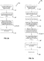
Figure 2c shows another implementation of themethod 20c according to the present principles. In this implementation, consideration is made for when two or more channels in the cable transmission are bonded (40). In this instance, and as described below) it is necessary to add the step of restricting (42) the number of carriers to be less than or equal to the number of carriers used in an OFDM symbol. The added step of ensuring (44) the generated preamble repeated in frequency fills the complete spectrum of the bonded channels is also required. -
Figure 7 shows anapparatus 70 for generating the DVB-C2 preamble according to the present principles. Aprocessor 72 in communication with a memory 74 andmodulator 76 controls the preamble generation by utilizing the below criterion and performing the steps for the same. Those of skill in the art will recognize that memory 74 can contain the variations in complementary sequences needed and theprocessor 72 will make determinations as to which complementary sequences are used during preamble generation so as to coordinate the same with the desired cable transmission application. - According to one preferred implementation, there are three criteria for the preamble structure:
- 1. The number of carriers used by the preamble, K p is confined by

- 2. The preamble, which carries the information of signals transmitted in the spectrum of the bonding channels, cyclically fill the complete spectrum. Furthermore, the preamble will cover the whole 8 MHz, i.e., 3584 carriers defined in DVB-T2. This criterion can be expressed as

- 3. Only the even carriers are modulated while the odd carriers are left as virtual carriers.
- The first and second criteria come up with the need to support Partial Reception in the receiver side when the Channel Bonding technique is applied in the transmitter side. By using the Channel Bonding technique, several channels are bonded together to provide a large spectrum. Thus, this large spectrum can be divided into subchannels or data slices according to the required bandwidth of individual service. To be more flexible, a subchannel or a data slice is allowed to start at any point (carrier) within the bonding spectrum. Then, the preamble has to be received and detected by a receiver at any tuning position within the bonding spectrum. It is worth noting that the guard band cannot be removed or reduced if Partial Reception is implemented in the receiver. Thus, the spectral efficiency does not have an apparent improvement when the Channel Bonding technique is used. When Channel Bonding and Partial Reception are not used, or there is a restriction for a subchannel such that a subchannel is not allowed to cross the boundary of two neighboring bonding channels, the first two criteria can be released. The third criterion is made so that the preamble has a repetition structure in time domain to enable fast preamble identification. This kind of structure is also used in IEEE 802.11 and 802.16. The repetition structure can be easily understood. Consider that we modulate even carriers only and leave all odd carriers as virtual carriers. From inverse DFT equation,


- If we normalize frequency offset by carrier spacing, the frequency offset can be separated as an integer part and a fractional part. The fractional part of frequency offset can be estimated by the time domain repetition structure. The estimation of integer part frequency offset has to rely on frequency domain pilots due to phase ambiguity problem for time domain signals. In at least one implementation in this disclosure, a complementary sequence is allocated in the frequency domain as shown in
Fig. 3 to assist integer frequency offset estimation. The length of the complementary sequence shall be selected according to the channel condition. There are 8 orthogonal complementary sequences of length 64 and 16 orthogonal complementary sequences of length 256, specified in DVB-T2 for the P1 preamble. Each of the complementary sequences of length 64 is made by a concatenation of a set of 8 complementary sequences of length 8. The 8 complementary sequences of length 64 are made by 8 orthogonal sets of complementary sequences. The complementary sequences of length 256 are made by the same way. They are made by 16 orthogonal sets of complementary sequences of length 16. For DVB-C2, one of the sequences with a length of 64 (124721741D482E7B in hexadecimal notation), is selected and allocated in the beginning of the preamble as shown inFig. 5 and Fig. 6 . The complementary sequence is allocated in the even carriers of the first 128 carriers. Note that we use a complementary sequence instead of 8 orthogonal complementary sequences which can convey 3 bit information implemented in DVB-T2. The processing time to estimate the integer part of frequency offset is decreased by doing so. - Two signaling methods are provided in the preamble.
- In this method, scattered pilot pattern PP5 is applied to the DVB-C2 system. However, there is a pilot for every 12 carriers in the preamble as shown in
Fig. 5 . The signaling bits are protected by BCH and LDPC codes and then mapped to QAM symbols in available even carriers. Signaling by this method can allow more information bits transmitted but the decoding complexity is larger than the signaling method described below. - According to the channel model recommended by DVB-C2 system evaluation (SE) group, the rms delay spread στ is equal to 97.5 ns. The coherence bandwidth which is defined as the bandwidth over which the frequency correlation function is above 0.9 is approximately

- Consider the 4k mode defined in DVB-T2, the subcarrier spacing is approximately 2.232 kHz. Thus, we can assume that the neighboring 205/2.232=91 carriers possess equal gain and linear phase. Thus, it is reasonable to assume that for a small number of neighboring subcarriers, e.g., 16, they have the same frequency domain channel gain coefficients. Taking advantage of this property, we can transmit orthogonal codes in neighboring subcarriers and decode them in the receiver by simply performing correlation. For instance, the
information bit 0 is transmitted by the code (1,1) and theinformation bit 1 is transmitted by the code (1,-1). In addition, the bits conveying system information should ideally be error free. Therefore, an error correction code added as shown inFig. 2 . The selection of the orthogonal codes and error correction codes depends on the number of required system information bits and the implementation complexity. The Walsh Code of length 8 is selected here for DVB-C2 preamble. The mapping of bits to Walsh code is given in Table 1 below:TABLE 1 Bits Walsh Code 000 1,1,1,1,1,1,1,1 001 1,-1,1,-1,1,-1,1,-1 010 1,1,-1,-1,1,1,-1,-1 011 1,-1,-1,1,1,-1,-1,1 100 1,1,1,1,-1,-1,-1,-1 101 1,.-1,1,-1,-1,1,-1,1 110 1,1,-1,-1,-1,-1,1,1 111 1,-1,-1,1,-1,1,1,-1 - Consider 4k mode defined in DVB-T2 and select K total equaling to 3408 (3409 in DVB-T2), from equation (1), the number of carriers in a preamble is K p ≤ 3408. In order to carry as much information as possible and fit the coding structure, K p is selected to be 3200. Thus, except the first 128 carriers which are allocated using a complementary sequence and, from
carrier index 128 to 3200, 192 sets of Walsh codes with length 8 are transmitted in even carriers. It is also possible to leave a small gap between the complementary sequence and Walsh code sets to have better performance of frequency offset estimation. A Walsh code of length 8 is able to convey 3 bits of information. Therefore, 576 information coding bits are transmitted. The Reed-Muller Code, RM(64,42,8) is selected to protect signaling bits of system information. Thus, the preamble can carry 378 signaling bits of system information. The total 576 bits are divided into 9 sets of 64 bits to carry 9 sets of 42 signaling bits of system information. The selection of the Reed-Muller code is due to its simplicity of decoding. If Walsh Code with length 4 and a more robust error correction code e.g., Reed-Solomon code are used, it is possible to carry more than 600 signaling bits. It is worth noting that by using this scheme to transmit signaling bits, no channel estimation is required in decoding signaling bits. Thus, the time delay is greatly reduced. - If we use the first signaling method, the channel gain coefficients on those pilot carriers in the preamble can be reuse in the following OFDM symbols. If the second signaling method is used, after we decode the system information bits, we can encode the decoding bits to get the original bits and thus transmitted orthogonal codes. Then, the channel gain coefficients in those modulated subcarriers can be easily obtained. It is worth noting that we get a much larger number of channel gain coefficients than what we get using the first signaling method. Since the cable channel is a stable channel, the channel gain coefficients obtained from the preamble are very helpful for channel estimation. The C2 system will be benefited by this initial channel estimation.
- Those of skill in the art will recognize that the present principles provide several advantages over known cable transmission techniques. Some examples of those advantages are:
- 1. The preamble designed in at least one implementation of this disclosure provides an N/2-point repetition structure in time domain where N is the size of FFT. This time domain structure can be used to perform preamble identification, frame timing synchronization and fractional frequency offset estimation in the same time. In addition, the required complexity is low and the performances of frame timing synchronization and fractional frequency offset estimation are better than CP-based method;
- 2. One of the signaling methods provided in to decode signaling bits transmitted in the preamble. Thus, the complexity is reduced and the delay time in processing the preamble is also reduced at least one implementation in this disclosure does not require channel estimation;
- 3. The designed preamble using orthogonal codes to transmitted signaling bits can provide additional initial channel gain coefficients (frequency domain channel gain coefficients in even carriers); and
- 4. The complexity of decoding the designed preamble structure in at least one implementation in this disclosure is smaller and hence the processing time (initial delay) for decoding the preamble is much shorter.
- These and other features and advantages of the present principles may be readily ascertained by one of ordinary skill in the pertinent art based on the teachings herein. It is to be understood that the teachings of the present principles may be implemented in various forms of hardware, software, firmware, special purpose processors, or combinations thereof.
- Most preferably, the teachings of the present principles are implemented as a combination of hardware and software. Moreover, the software may be implemented as an application program tangibly embodied on a program storage unit. The application program may be uploaded to, and executed by, a machine comprising any suitable architecture. Preferably, the machine is implemented on a computer platform having hardware such as one or more central processing units ("CPU"), a random access memory ("RAM"), and input/output ("I/O") interfaces. The computer platform may also include an operating system and microinstruction code. The various processes and functions described herein may be either part of the microinstruction code or part of the application program, or any combination thereof, which may be executed by a CPU. In addition, various other peripheral units may be connected to the computer platform such as an additional data storage unit and a printing unit.
- It is to be further understood that, because some of the constituent system components and methods depicted in the accompanying drawings are preferably implemented in software, the actual connections between the system components or the process function blocks may differ depending upon the manner in which the present principles are programmed. Given the teachings herein, one of ordinary skill in the pertinent art will be able to contemplate these and similar implementations or configurations of the present principles.
- Although the illustrative embodiments have been described herein with reference to the accompanying drawings, it is to be understood that the present principles is not limited to those precise embodiments, and that various changes and modifications may be effected therein by one of ordinary skill in the pertinent art without departing from the scope of the present principles. All such changes and modifications are intended to be included within the scope of the present principles as set forth in the appended claims.
Claims (15)
- A method for generating a preamble for use in a cable transmission system, the method comprising the steps of:inserting (22) a selected complementary sequence having a length according to cable channel conditions as a header into even numbered (32) beginning carriers of a preamble frequency domain representation, said beginning carriers being lowest frequency carriers;mapping (24) the complementary sequence into modulation symbols allocated to the even numbered (32) beginning carriers;protecting (28) signaling bits of the system (26) with error correction codes;mapping (30) the protected signaling bits into modulation symbols of orthogonal codes allocated to adjacent even numbered (32) subsequent carriers having the same frequency domain channel gain coefficients, the subsequent carriers being subsequent to the beginning carriers; andtransforming (34) the preamble to a time domain.
- The method according to claim 1, further comprising selecting the orthogonal codes in response to a number of required system information bits and channel conditions.
- The method according to claim 1, further comprising the step of adding a cyclic prefix to complete the generation of the preamble.
- The method according to claim 1, further comprising:bonding (40) two or more channels;ensuring (44) the generated preamble repeated in frequency fills a complete spectrum of the bonded channels; andrestricting (42) a number of carriers used by said preamble to be less than or equal to a number of carriers used in an Orthogonal Frequency Division Multiplexing, OFDM, symbol.
- The method according to claim 1, further comprising:
restricting (42) a number of carriers used by said preamble to be less than or equal to a number of carriers used in an Orthogonal Frequency Division Multiplexing, OFDM, symbol. - The method according to claim 1, wherein said error correction codes comprise Reed-Muller codes.
- The method according to claim 2, wherein the orthogonal codes comprise Walsh codes.
- An apparatus adapted to generate a preamble for use in a cable transmission system, the apparatus comprising:a processor (72) adapted to insert a selected complementary sequence having a length according to cable channel conditions as a header into even numbered beginning carriers of a preamble frequency domain representation, said beginning carriers being lowest frequency carriers, for protecting signaling bits of the system with error correction codes, the processor adapted to map the protected signaling bits into orthogonal codes and adapted to map the complementary sequence and the orthogonal codes into modulation symbols to form the preamble, the processor adapted to transform the preamble to the time domain; anda modulator (76) configured to allocate the modulation symbols of the complementary sequence to the even numbered beginning carriers and to allocate the modulation symbols of the orthogonal codes to adjacent even numbered subsequent carriers having the same frequency domain channel gain coefficients, the subsequent carriers being subsequent to the beginning carriers.
- A method for receiving and processing a preamble used in a cable transmission system, the method comprising the steps of:transforming the preamble from the time domain;de-mapping modulation symbols allocated on even numbered beginning carriers of a preamble frequency domain representation into a selected complementary sequence having a length according to cable channel conditions, said beginning carriers being lowest frequency carriers;de-mapping modulation symbols into orthogonal codes allocated on adjacent even numbered subsequent carriers having the same frequency domain channel gain coefficients, said subsequent carriers being subsequent to the beginning carriers;decoding the orthogonal codes into protected signaling bits;decoding error correction codes to recover signaling bits of the system from the protected signaling bits; andremoving the complementary sequence as a header in the even numbered beginning carriers.
- An apparatus adapted to receive and process a preamble used in a cable transmission system, the apparatus comprising:a demodulator configured to de-map modulation symbols allocated on the even numbered beginning carriers of the preamble frequency domain representation into a selected complementary sequence having a length according to cable channel conditions, said beginning carriers being lowest frequency carriers, and configured to de-map modulation symbols into orthogonal codes allocated on adjacent even numbered subsequent carriers having the same frequency domain channel gain coefficients, said subsequent carriers being subsequent to the beginning carriers; anda processor configured to transform the preamble from the time domain, configured to decode the orthogonal codes into protected signaling bits, configured to decode error correction codes to recover signaling bits of the system from the protected signaling bits, and configured to remove the complementary sequence as a header in the even numbered beginning carriers.
- The method of claim 9, wherein the channel gain coefficients of the preamble are used for channel estimation.
- The apparatus of claim 10, wherein the processor further uses the channel gain coefficients of the preamble for channel estimation.
- The apparatus of claim 8, wherein the processor is further adapted to select the orthogonal codes in response to a number of required system information bits and channel conditions.
- The apparatus of claim 8, wherein the processor is further adapted to add a cyclic prefix to complete the generation of the preamble.
- A computer readable media comprising instructions which, when executed by a computer, cause the computer to carry out the steps of a method according to any of the claims 1 to 7 or 9 and 11.
Applications Claiming Priority (2)
| Application Number | Priority Date | Filing Date | Title |
|---|---|---|---|
| US19674608P | 2008-10-20 | 2008-10-20 | |
| PCT/US2009/005717 WO2010047787A2 (en) | 2008-10-20 | 2009-10-20 | Method and apparatus for generating a preamble for use in cable transmission systems |
Publications (2)
| Publication Number | Publication Date |
|---|---|
| EP2347538A2 EP2347538A2 (en) | 2011-07-27 |
| EP2347538B1 true EP2347538B1 (en) | 2018-08-22 |
Family
ID=42060674
Family Applications (1)
| Application Number | Title | Priority Date | Filing Date |
|---|---|---|---|
| EP09752234.6A Active EP2347538B1 (en) | 2008-10-20 | 2009-10-20 | Method and apparatus for generating a preamble for use in cable transmission systems |
Country Status (7)
| Country | Link |
|---|---|
| US (1) | US8649450B2 (en) |
| EP (1) | EP2347538B1 (en) |
| JP (1) | JP5559799B2 (en) |
| KR (1) | KR101640595B1 (en) |
| CN (1) | CN102187634B (en) |
| BR (1) | BRPI0920429B1 (en) |
| WO (1) | WO2010047787A2 (en) |
Families Citing this family (13)
| Publication number | Priority date | Publication date | Assignee | Title |
|---|---|---|---|---|
| KR101518346B1 (en) | 2008-10-20 | 2015-05-08 | 삼성전자주식회사 | A method for receiving and transmitting preamble in a OFDM system and an apparatus thereof |
| US9313531B2 (en) | 2010-10-06 | 2016-04-12 | Thomson Licensing | Device and method for content delivery adapted for synchronous playbacks |
| CN105450277B (en) * | 2010-12-10 | 2018-11-20 | 太阳专利托管公司 | Sending method and transmission system and method for reseptance and reception device |
| JP5648500B2 (en) * | 2011-01-28 | 2015-01-07 | 富士通セミコンダクター株式会社 | Transmission device, transmission method, reception device, and reception method |
| US20130315323A1 (en) * | 2011-04-24 | 2013-11-28 | Broadcom Corporation | Traveling pilots within single user, multiple user, multiple access, and/or MIMO wireless communications |
| EP2634945B1 (en) | 2012-02-29 | 2014-12-24 | Mitsubishi Electric R&D Centre Europe B.V. | Method and a device for increasing the amount of information bits comprised in a symbol |
| JP5992916B2 (en) * | 2012-03-13 | 2016-09-14 | パナソニック株式会社 | Wireless communication device |
| WO2016068406A1 (en) * | 2014-10-27 | 2016-05-06 | Samsung Electronics Co., Ltd. | Additional channels using preamble symbols |
| JP6401062B2 (en) * | 2015-01-06 | 2018-10-03 | Kddi株式会社 | Wireless communication apparatus, wireless communication method and program |
| WO2016204435A1 (en) * | 2015-06-18 | 2016-12-22 | 엘지전자 주식회사 | Channel bonding based signal transmission method and apparatus therefor |
| US10136287B2 (en) * | 2015-07-09 | 2018-11-20 | Electronics And Telecommunications Research Institute | Method and apparatus for close proximity communications |
| CN113395776B (en) | 2017-03-28 | 2023-09-08 | Lg 电子株式会社 | Method for transmitting and receiving signal in wireless LAN system and apparatus therefor |
| EP4085582A1 (en) * | 2019-12-30 | 2022-11-09 | Sony Group Corporation | Communication devices and methods |
Family Cites Families (14)
| Publication number | Priority date | Publication date | Assignee | Title |
|---|---|---|---|---|
| ATE233451T1 (en) | 1996-09-02 | 2003-03-15 | St Microelectronics Nv | IMPROVEMENTS IN, OR RELATING TO, MULTI CARRIER TRANSMISSION SYSTEMS |
| US7613183B1 (en) | 2000-10-31 | 2009-11-03 | Foundry Networks, Inc. | System and method for router data aggregation and delivery |
| KR100946913B1 (en) | 2003-11-21 | 2010-03-09 | 삼성전자주식회사 | Apparatus of generating preamble signal for cell identification in an orthogonal frequency division multiple system and the method thereof |
| KR100868679B1 (en) | 2005-06-01 | 2008-11-13 | 삼성전자주식회사 | Apparatus and method for transmitting and receiving preamble signal in wireless communication system |
| EP1894335B1 (en) * | 2005-06-22 | 2019-11-13 | Samsung Electronics Co., Ltd. | Method and transmission apparatus for allocating resources to transmit uplink packet data in an orthogonal frequency division multiplexing system |
| US20070070934A1 (en) | 2005-09-28 | 2007-03-29 | Pieter Van Rooyen | Method and system for a reconfigurable OFDM radio supporting diversity |
| US20070070179A1 (en) * | 2005-09-28 | 2007-03-29 | Pieter Van Rooyen | Method and system for a reconfigurable OFDM radio |
| WO2007078146A1 (en) * | 2006-01-06 | 2007-07-12 | Samsung Electronics Co., Ltd. | Method and apparatus for transmitting/receiving uplink signaling information in a single carrier fdma system |
| JP4645479B2 (en) | 2006-02-28 | 2011-03-09 | パナソニック株式会社 | Wireless device and program |
| US7974254B2 (en) | 2007-10-22 | 2011-07-05 | Nokia Corporation | Digital broadcast signaling metadata |
| EP3487134B1 (en) | 2008-01-29 | 2021-12-22 | Samsung Electronics Co., Ltd. | Method for transmitting and receiving preambles in a digital video broadcasting system |
| ES2431337T3 (en) * | 2008-06-04 | 2013-11-26 | Sony Corporation | New frame structure for multiple carrier systems |
| KR101518346B1 (en) | 2008-10-20 | 2015-05-08 | 삼성전자주식회사 | A method for receiving and transmitting preamble in a OFDM system and an apparatus thereof |
| US8340222B2 (en) * | 2009-12-24 | 2012-12-25 | Intel Corporation | Parameter and scattered pilot based symbol timing recovery |
-
2009
- 2009-10-20 KR KR1020117011383A patent/KR101640595B1/en active IP Right Grant
- 2009-10-20 US US12/998,442 patent/US8649450B2/en active Active
- 2009-10-20 CN CN200980141623.8A patent/CN102187634B/en active Active
- 2009-10-20 EP EP09752234.6A patent/EP2347538B1/en active Active
- 2009-10-20 WO PCT/US2009/005717 patent/WO2010047787A2/en active Application Filing
- 2009-10-20 BR BRPI0920429-6A patent/BRPI0920429B1/en active IP Right Grant
- 2009-10-20 JP JP2011532098A patent/JP5559799B2/en active Active
Non-Patent Citations (1)
| Title |
|---|
| None * |
Also Published As
| Publication number | Publication date |
|---|---|
| JP5559799B2 (en) | 2014-07-23 |
| CN102187634B (en) | 2014-01-22 |
| KR20110086091A (en) | 2011-07-27 |
| JP2012506208A (en) | 2012-03-08 |
| KR101640595B1 (en) | 2016-07-18 |
| US8649450B2 (en) | 2014-02-11 |
| US20110194625A1 (en) | 2011-08-11 |
| WO2010047787A2 (en) | 2010-04-29 |
| CN102187634A (en) | 2011-09-14 |
| BRPI0920429B1 (en) | 2021-01-19 |
| WO2010047787A3 (en) | 2010-10-14 |
| EP2347538A2 (en) | 2011-07-27 |
| BRPI0920429A2 (en) | 2020-07-14 |
Similar Documents
| Publication | Publication Date | Title |
|---|---|---|
| EP2347538B1 (en) | Method and apparatus for generating a preamble for use in cable transmission systems | |
| US10938876B2 (en) | Method and system for low data rate transmission | |
| JP4819130B2 (en) | Method and apparatus for generating and transmitting a code sequence in a wireless communication system | |
| EP1936902B1 (en) | Sequence generating method for detection and method for transmitting and receiving signals using the same | |
| US9942011B2 (en) | Wireless communication apparatus and the method thereof | |
| CN101356755B (en) | Method and apparatus for pilot signal transmission | |
| RU2637115C2 (en) | Device for transmitting and receiving signal and method for transmitting and receiving signal | |
| KR100922950B1 (en) | Apparatus and method for transmitting and receiving process result of a data frame in a orthogonal frequency division multiple system | |
| CN1310459C (en) | Channel estimation in a multi carrier transmit diversity system | |
| JP5016597B2 (en) | Method for transmitting and receiving signals with distributed training symbols in a mobile communication system | |
| KR101445388B1 (en) | Method of Transmitting Data using Repetition Coding | |
| US20090245399A1 (en) | Method and apparatus for inserting guard interval in a mobile communication system | |
| KR100742128B1 (en) | Apparatus and method for estimating uplink frequency offset in orthogonal frequency division multiplexing communication system | |
| US20100157918A1 (en) | Method and apparatus for allocating demodulation reference signals | |
| US20080165892A1 (en) | Using the Preamble in an OFDM-Based Communications System to Indicate the Number of Guard Tones | |
| WO2019008916A1 (en) | Radio transmission device and transmission method | |
| US8588153B2 (en) | Method and apparatus for transmitting uplink control channel in a mobile communication system | |
| US9210020B1 (en) | System and method for suppressing PAPR in MC-CDMA and derivatives | |
| WO2009043311A1 (en) | Time-frequency spreading method and apparatus in ofdma system | |
| KR100969771B1 (en) | Apparatus and method for transmitting and receiving a signal in a communication system | |
| US8000398B2 (en) | Time division synchronous orthogonal frequency division multiplexing supporting frequency division multiple access | |
| US20060109924A1 (en) | Apparatus and method for signal transmission/reception according to pilot modulation in a multi-carrier communication system | |
| TWI413369B (en) | Method and apparatus for transmitting pilot symbols in wireless communication system | |
| RU2391789C2 (en) | Method and device for generation and transfer of code sequence in system of wireless communication |
Legal Events
| Date | Code | Title | Description |
|---|---|---|---|
| PUAI | Public reference made under article 153(3) epc to a published international application that has entered the european phase |
Free format text: ORIGINAL CODE: 0009012 |
|
| 17P | Request for examination filed |
Effective date: 20110420 |
|
| AK | Designated contracting states |
Kind code of ref document: A2 Designated state(s): AT BE BG CH CY CZ DE DK EE ES FI FR GB GR HR HU IE IS IT LI LT LU LV MC MK MT NL NO PL PT RO SE SI SK SM TR |
|
| AX | Request for extension of the european patent |
Extension state: AL BA RS |
|
| DAX | Request for extension of the european patent (deleted) | ||
| 17Q | First examination report despatched |
Effective date: 20130917 |
|
| GRAP | Despatch of communication of intention to grant a patent |
Free format text: ORIGINAL CODE: EPIDOSNIGR1 |
|
| RIC1 | Information provided on ipc code assigned before grant |
Ipc: H04L 27/26 20060101ALI20170928BHEP Ipc: H04L 1/00 20060101ALN20170928BHEP Ipc: H04L 5/00 20060101AFI20170928BHEP |
|
| RIC1 | Information provided on ipc code assigned before grant |
Ipc: H04L 1/00 20060101ALN20171012BHEP Ipc: H04L 27/26 20060101ALI20171012BHEP Ipc: H04L 5/00 20060101AFI20171012BHEP |
|
| INTG | Intention to grant announced |
Effective date: 20171023 |
|
| GRAS | Grant fee paid |
Free format text: ORIGINAL CODE: EPIDOSNIGR3 |
|
| GRAJ | Information related to disapproval of communication of intention to grant by the applicant or resumption of examination proceedings by the epo deleted |
Free format text: ORIGINAL CODE: EPIDOSDIGR1 |
|
| GRAL | Information related to payment of fee for publishing/printing deleted |
Free format text: ORIGINAL CODE: EPIDOSDIGR3 |
|
| GRAP | Despatch of communication of intention to grant a patent |
Free format text: ORIGINAL CODE: EPIDOSNIGR1 |
|
| INTC | Intention to grant announced (deleted) | ||
| RIC1 | Information provided on ipc code assigned before grant |
Ipc: H04L 1/00 20060101ALN20180308BHEP Ipc: H04L 5/00 20060101AFI20180308BHEP Ipc: H04L 27/26 20060101ALI20180308BHEP |
|
| INTG | Intention to grant announced |
Effective date: 20180326 |
|
| GRAA | (expected) grant |
Free format text: ORIGINAL CODE: 0009210 |
|
| AK | Designated contracting states |
Kind code of ref document: B1 Designated state(s): AT BE BG CH CY CZ DE DK EE ES FI FR GB GR HR HU IE IS IT LI LT LU LV MC MK MT NL NO PL PT RO SE SI SK SM TR |
|
| REG | Reference to a national code |
Ref country code: GB Ref legal event code: FG4D |
|
| REG | Reference to a national code |
Ref country code: CH Ref legal event code: EP |
|
| REG | Reference to a national code |
Ref country code: AT Ref legal event code: REF Ref document number: 1033717 Country of ref document: AT Kind code of ref document: T Effective date: 20180915 |
|
| REG | Reference to a national code |
Ref country code: IE Ref legal event code: FG4D |
|
| REG | Reference to a national code |
Ref country code: DE Ref legal event code: R096 Ref document number: 602009054018 Country of ref document: DE |
|
| REG | Reference to a national code |
Ref country code: FR Ref legal event code: PLFP Year of fee payment: 10 |
|
| REG | Reference to a national code |
Ref country code: NL Ref legal event code: FP |
|
| REG | Reference to a national code |
Ref country code: LT Ref legal event code: MG4D |
|
| PG25 | Lapsed in a contracting state [announced via postgrant information from national office to epo] |
Ref country code: FI Free format text: LAPSE BECAUSE OF FAILURE TO SUBMIT A TRANSLATION OF THE DESCRIPTION OR TO PAY THE FEE WITHIN THE PRESCRIBED TIME-LIMIT Effective date: 20180822 Ref country code: IS Free format text: LAPSE BECAUSE OF FAILURE TO SUBMIT A TRANSLATION OF THE DESCRIPTION OR TO PAY THE FEE WITHIN THE PRESCRIBED TIME-LIMIT Effective date: 20181222 Ref country code: BG Free format text: LAPSE BECAUSE OF FAILURE TO SUBMIT A TRANSLATION OF THE DESCRIPTION OR TO PAY THE FEE WITHIN THE PRESCRIBED TIME-LIMIT Effective date: 20181122 Ref country code: SE Free format text: LAPSE BECAUSE OF FAILURE TO SUBMIT A TRANSLATION OF THE DESCRIPTION OR TO PAY THE FEE WITHIN THE PRESCRIBED TIME-LIMIT Effective date: 20180822 Ref country code: GR Free format text: LAPSE BECAUSE OF FAILURE TO SUBMIT A TRANSLATION OF THE DESCRIPTION OR TO PAY THE FEE WITHIN THE PRESCRIBED TIME-LIMIT Effective date: 20181123 Ref country code: LT Free format text: LAPSE BECAUSE OF FAILURE TO SUBMIT A TRANSLATION OF THE DESCRIPTION OR TO PAY THE FEE WITHIN THE PRESCRIBED TIME-LIMIT Effective date: 20180822 Ref country code: NO Free format text: LAPSE BECAUSE OF FAILURE TO SUBMIT A TRANSLATION OF THE DESCRIPTION OR TO PAY THE FEE WITHIN THE PRESCRIBED TIME-LIMIT Effective date: 20181122 |
|
| REG | Reference to a national code |
Ref country code: AT Ref legal event code: MK05 Ref document number: 1033717 Country of ref document: AT Kind code of ref document: T Effective date: 20180822 |
|
| PG25 | Lapsed in a contracting state [announced via postgrant information from national office to epo] |
Ref country code: ES Free format text: LAPSE BECAUSE OF FAILURE TO SUBMIT A TRANSLATION OF THE DESCRIPTION OR TO PAY THE FEE WITHIN THE PRESCRIBED TIME-LIMIT Effective date: 20180822 Ref country code: HR Free format text: LAPSE BECAUSE OF FAILURE TO SUBMIT A TRANSLATION OF THE DESCRIPTION OR TO PAY THE FEE WITHIN THE PRESCRIBED TIME-LIMIT Effective date: 20180822 Ref country code: LV Free format text: LAPSE BECAUSE OF FAILURE TO SUBMIT A TRANSLATION OF THE DESCRIPTION OR TO PAY THE FEE WITHIN THE PRESCRIBED TIME-LIMIT Effective date: 20180822 |
|
| PG25 | Lapsed in a contracting state [announced via postgrant information from national office to epo] |
Ref country code: AT Free format text: LAPSE BECAUSE OF FAILURE TO SUBMIT A TRANSLATION OF THE DESCRIPTION OR TO PAY THE FEE WITHIN THE PRESCRIBED TIME-LIMIT Effective date: 20180822 Ref country code: EE Free format text: LAPSE BECAUSE OF FAILURE TO SUBMIT A TRANSLATION OF THE DESCRIPTION OR TO PAY THE FEE WITHIN THE PRESCRIBED TIME-LIMIT Effective date: 20180822 Ref country code: RO Free format text: LAPSE BECAUSE OF FAILURE TO SUBMIT A TRANSLATION OF THE DESCRIPTION OR TO PAY THE FEE WITHIN THE PRESCRIBED TIME-LIMIT Effective date: 20180822 Ref country code: IT Free format text: LAPSE BECAUSE OF FAILURE TO SUBMIT A TRANSLATION OF THE DESCRIPTION OR TO PAY THE FEE WITHIN THE PRESCRIBED TIME-LIMIT Effective date: 20180822 Ref country code: CZ Free format text: LAPSE BECAUSE OF FAILURE TO SUBMIT A TRANSLATION OF THE DESCRIPTION OR TO PAY THE FEE WITHIN THE PRESCRIBED TIME-LIMIT Effective date: 20180822 Ref country code: PL Free format text: LAPSE BECAUSE OF FAILURE TO SUBMIT A TRANSLATION OF THE DESCRIPTION OR TO PAY THE FEE WITHIN THE PRESCRIBED TIME-LIMIT Effective date: 20180822 |
|
| REG | Reference to a national code |
Ref country code: DE Ref legal event code: R097 Ref document number: 602009054018 Country of ref document: DE |
|
| PG25 | Lapsed in a contracting state [announced via postgrant information from national office to epo] |
Ref country code: SM Free format text: LAPSE BECAUSE OF FAILURE TO SUBMIT A TRANSLATION OF THE DESCRIPTION OR TO PAY THE FEE WITHIN THE PRESCRIBED TIME-LIMIT Effective date: 20180822 Ref country code: DK Free format text: LAPSE BECAUSE OF FAILURE TO SUBMIT A TRANSLATION OF THE DESCRIPTION OR TO PAY THE FEE WITHIN THE PRESCRIBED TIME-LIMIT Effective date: 20180822 Ref country code: SK Free format text: LAPSE BECAUSE OF FAILURE TO SUBMIT A TRANSLATION OF THE DESCRIPTION OR TO PAY THE FEE WITHIN THE PRESCRIBED TIME-LIMIT Effective date: 20180822 |
|
| REG | Reference to a national code |
Ref country code: CH Ref legal event code: PL |
|
| REG | Reference to a national code |
Ref country code: BE Ref legal event code: MM Effective date: 20181031 |
|
| PG25 | Lapsed in a contracting state [announced via postgrant information from national office to epo] |
Ref country code: LU Free format text: LAPSE BECAUSE OF NON-PAYMENT OF DUE FEES Effective date: 20181020 Ref country code: MC Free format text: LAPSE BECAUSE OF FAILURE TO SUBMIT A TRANSLATION OF THE DESCRIPTION OR TO PAY THE FEE WITHIN THE PRESCRIBED TIME-LIMIT Effective date: 20180822 |
|
| PLBE | No opposition filed within time limit |
Free format text: ORIGINAL CODE: 0009261 |
|
| STAA | Information on the status of an ep patent application or granted ep patent |
Free format text: STATUS: NO OPPOSITION FILED WITHIN TIME LIMIT |
|
| REG | Reference to a national code |
Ref country code: IE Ref legal event code: MM4A |
|
| 26N | No opposition filed |
Effective date: 20190523 |
|
| PG25 | Lapsed in a contracting state [announced via postgrant information from national office to epo] |
Ref country code: SI Free format text: LAPSE BECAUSE OF FAILURE TO SUBMIT A TRANSLATION OF THE DESCRIPTION OR TO PAY THE FEE WITHIN THE PRESCRIBED TIME-LIMIT Effective date: 20180822 Ref country code: LI Free format text: LAPSE BECAUSE OF NON-PAYMENT OF DUE FEES Effective date: 20181031 Ref country code: CH Free format text: LAPSE BECAUSE OF NON-PAYMENT OF DUE FEES Effective date: 20181031 Ref country code: BE Free format text: LAPSE BECAUSE OF NON-PAYMENT OF DUE FEES Effective date: 20181031 |
|
| REG | Reference to a national code |
Ref country code: GB Ref legal event code: 732E Free format text: REGISTERED BETWEEN 20190822 AND 20190828 |
|
| PG25 | Lapsed in a contracting state [announced via postgrant information from national office to epo] |
Ref country code: IE Free format text: LAPSE BECAUSE OF NON-PAYMENT OF DUE FEES Effective date: 20181020 |
|
| PG25 | Lapsed in a contracting state [announced via postgrant information from national office to epo] |
Ref country code: MT Free format text: LAPSE BECAUSE OF NON-PAYMENT OF DUE FEES Effective date: 20181020 |
|
| PG25 | Lapsed in a contracting state [announced via postgrant information from national office to epo] |
Ref country code: TR Free format text: LAPSE BECAUSE OF FAILURE TO SUBMIT A TRANSLATION OF THE DESCRIPTION OR TO PAY THE FEE WITHIN THE PRESCRIBED TIME-LIMIT Effective date: 20180822 |
|
| PG25 | Lapsed in a contracting state [announced via postgrant information from national office to epo] |
Ref country code: PT Free format text: LAPSE BECAUSE OF FAILURE TO SUBMIT A TRANSLATION OF THE DESCRIPTION OR TO PAY THE FEE WITHIN THE PRESCRIBED TIME-LIMIT Effective date: 20180822 |
|
| PG25 | Lapsed in a contracting state [announced via postgrant information from national office to epo] |
Ref country code: MK Free format text: LAPSE BECAUSE OF NON-PAYMENT OF DUE FEES Effective date: 20180822 Ref country code: HU Free format text: LAPSE BECAUSE OF FAILURE TO SUBMIT A TRANSLATION OF THE DESCRIPTION OR TO PAY THE FEE WITHIN THE PRESCRIBED TIME-LIMIT; INVALID AB INITIO Effective date: 20091020 Ref country code: CY Free format text: LAPSE BECAUSE OF FAILURE TO SUBMIT A TRANSLATION OF THE DESCRIPTION OR TO PAY THE FEE WITHIN THE PRESCRIBED TIME-LIMIT Effective date: 20180822 |
|
| REG | Reference to a national code |
Ref country code: DE Ref legal event code: R081 Ref document number: 602009054018 Country of ref document: DE Owner name: INTERDIGITAL CE PATENT HOLDINGS, SAS, FR Free format text: FORMER OWNER: THOMSON LICENSING, ISSY-LES-MOULINEAUX, FR |
|
| REG | Reference to a national code |
Ref country code: NL Ref legal event code: PD Owner name: INTERDIGITAL CE PATENT HOLDINGS, SAS; FR Free format text: DETAILS ASSIGNMENT: CHANGE OF OWNER(S), ASSIGNMENT; FORMER OWNER NAME: THOMSON LICENSING Effective date: 20211014 |
|
| PGFP | Annual fee paid to national office [announced via postgrant information from national office to epo] |
Ref country code: NL Payment date: 20231026 Year of fee payment: 15 |
|
| PGFP | Annual fee paid to national office [announced via postgrant information from national office to epo] |
Ref country code: GB Payment date: 20231024 Year of fee payment: 15 |
|
| PGFP | Annual fee paid to national office [announced via postgrant information from national office to epo] |
Ref country code: FR Payment date: 20231026 Year of fee payment: 15 Ref country code: DE Payment date: 20231027 Year of fee payment: 15 |