EP2346304A1 - Wärmeübertrager - Google Patents
Wärmeübertrager Download PDFInfo
- Publication number
- EP2346304A1 EP2346304A1 EP10290021A EP10290021A EP2346304A1 EP 2346304 A1 EP2346304 A1 EP 2346304A1 EP 10290021 A EP10290021 A EP 10290021A EP 10290021 A EP10290021 A EP 10290021A EP 2346304 A1 EP2346304 A1 EP 2346304A1
- Authority
- EP
- European Patent Office
- Prior art keywords
- cavity
- heat
- cavity wall
- electrical resistance
- heat exchanger
- Prior art date
- Legal status (The legal status is an assumption and is not a legal conclusion. Google has not performed a legal analysis and makes no representation as to the accuracy of the status listed.)
- Granted
Links
Images


Classifications
-
- H—ELECTRICITY
- H05—ELECTRIC TECHNIQUES NOT OTHERWISE PROVIDED FOR
- H05B—ELECTRIC HEATING; ELECTRIC LIGHT SOURCES NOT OTHERWISE PROVIDED FOR; CIRCUIT ARRANGEMENTS FOR ELECTRIC LIGHT SOURCES, IN GENERAL
- H05B3/00—Ohmic-resistance heating
- H05B3/40—Heating elements having the shape of rods or tubes
- H05B3/42—Heating elements having the shape of rods or tubes non-flexible
- H05B3/44—Heating elements having the shape of rods or tubes non-flexible heating conductor arranged within rods or tubes of insulating material
-
- B—PERFORMING OPERATIONS; TRANSPORTING
- B60—VEHICLES IN GENERAL
- B60H—ARRANGEMENTS OF HEATING, COOLING, VENTILATING OR OTHER AIR-TREATING DEVICES SPECIALLY ADAPTED FOR PASSENGER OR GOODS SPACES OF VEHICLES
- B60H1/00—Heating, cooling or ventilating devices
- B60H1/22—Heating, cooling or ventilating devices the heat source being other than the propulsion plant
- B60H1/2215—Heating, cooling or ventilating devices the heat source being other than the propulsion plant the heat being derived from electric heaters
- B60H1/2225—Heating, cooling or ventilating devices the heat source being other than the propulsion plant the heat being derived from electric heaters arrangements of electric heaters for heating air
-
- H—ELECTRICITY
- H05—ELECTRIC TECHNIQUES NOT OTHERWISE PROVIDED FOR
- H05B—ELECTRIC HEATING; ELECTRIC LIGHT SOURCES NOT OTHERWISE PROVIDED FOR; CIRCUIT ARRANGEMENTS FOR ELECTRIC LIGHT SOURCES, IN GENERAL
- H05B3/00—Ohmic-resistance heating
- H05B3/20—Heating elements having extended surface area substantially in a two-dimensional [2D] plane, e.g. plate-heater
- H05B3/22—Heating elements having extended surface area substantially in a two-dimensional [2D] plane, e.g. plate-heater non-flexible
- H05B3/26—Heating elements having extended surface area substantially in a two-dimensional [2D] plane, e.g. plate-heater non-flexible heating conductor mounted on insulating base
- H05B3/267—Heating elements having extended surface area substantially in a two-dimensional [2D] plane, e.g. plate-heater non-flexible heating conductor mounted on insulating base the insulating base being an organic material, e.g. plastic
-
- B—PERFORMING OPERATIONS; TRANSPORTING
- B60—VEHICLES IN GENERAL
- B60H—ARRANGEMENTS OF HEATING, COOLING, VENTILATING OR OTHER AIR-TREATING DEVICES SPECIALLY ADAPTED FOR PASSENGER OR GOODS SPACES OF VEHICLES
- B60H1/00—Heating, cooling or ventilating devices
- B60H1/22—Heating, cooling or ventilating devices the heat source being other than the propulsion plant
- B60H2001/2268—Constructional features
- B60H2001/2278—Connectors, water supply, housing, mounting brackets
-
- B—PERFORMING OPERATIONS; TRANSPORTING
- B60—VEHICLES IN GENERAL
- B60H—ARRANGEMENTS OF HEATING, COOLING, VENTILATING OR OTHER AIR-TREATING DEVICES SPECIALLY ADAPTED FOR PASSENGER OR GOODS SPACES OF VEHICLES
- B60H1/00—Heating, cooling or ventilating devices
- B60H1/22—Heating, cooling or ventilating devices the heat source being other than the propulsion plant
- B60H2001/2268—Constructional features
- B60H2001/2287—Integration into a vehicle HVAC system or vehicle dashboard
-
- F—MECHANICAL ENGINEERING; LIGHTING; HEATING; WEAPONS; BLASTING
- F28—HEAT EXCHANGE IN GENERAL
- F28D—HEAT-EXCHANGE APPARATUS, NOT PROVIDED FOR IN ANOTHER SUBCLASS, IN WHICH THE HEAT-EXCHANGE MEDIA DO NOT COME INTO DIRECT CONTACT
- F28D21/00—Heat-exchange apparatus not covered by any of the groups F28D1/00 - F28D20/00
- F28D2021/0019—Other heat exchangers for particular applications; Heat exchange systems not otherwise provided for
- F28D2021/008—Other heat exchangers for particular applications; Heat exchange systems not otherwise provided for for vehicles
- F28D2021/0091—Radiators
- F28D2021/0096—Radiators for space heating
-
- F—MECHANICAL ENGINEERING; LIGHTING; HEATING; WEAPONS; BLASTING
- F28—HEAT EXCHANGE IN GENERAL
- F28F—DETAILS OF HEAT-EXCHANGE AND HEAT-TRANSFER APPARATUS, OF GENERAL APPLICATION
- F28F2265/00—Safety or protection arrangements; Arrangements for preventing malfunction
- F28F2265/24—Safety or protection arrangements; Arrangements for preventing malfunction for electrical insulation
-
- H—ELECTRICITY
- H05—ELECTRIC TECHNIQUES NOT OTHERWISE PROVIDED FOR
- H05B—ELECTRIC HEATING; ELECTRIC LIGHT SOURCES NOT OTHERWISE PROVIDED FOR; CIRCUIT ARRANGEMENTS FOR ELECTRIC LIGHT SOURCES, IN GENERAL
- H05B2203/00—Aspects relating to Ohmic resistive heating covered by group H05B3/00
- H05B2203/009—Heaters using conductive material in contact with opposing surfaces of the resistive element or resistive layer
-
- H—ELECTRICITY
- H05—ELECTRIC TECHNIQUES NOT OTHERWISE PROVIDED FOR
- H05B—ELECTRIC HEATING; ELECTRIC LIGHT SOURCES NOT OTHERWISE PROVIDED FOR; CIRCUIT ARRANGEMENTS FOR ELECTRIC LIGHT SOURCES, IN GENERAL
- H05B2203/00—Aspects relating to Ohmic resistive heating covered by group H05B3/00
- H05B2203/02—Heaters using heating elements having a positive temperature coefficient
-
- H—ELECTRICITY
- H05—ELECTRIC TECHNIQUES NOT OTHERWISE PROVIDED FOR
- H05B—ELECTRIC HEATING; ELECTRIC LIGHT SOURCES NOT OTHERWISE PROVIDED FOR; CIRCUIT ARRANGEMENTS FOR ELECTRIC LIGHT SOURCES, IN GENERAL
- H05B2203/00—Aspects relating to Ohmic resistive heating covered by group H05B3/00
- H05B2203/022—Heaters specially adapted for heating gaseous material
- H05B2203/023—Heaters of the type used for electrically heating the air blown in a vehicle compartment by the vehicle heating system
Definitions
- the invention relates to a heat exchanger according to the preamble of claim 1, an automotive air conditioning system according to the preamble of claim 10 and a method for producing a heat exchanger or an automotive air conditioning system according to the preamble of claim 11.
- Automotive air conditioning systems serve to heat and / or to cool the air to be supplied to the interior of a motor vehicle.
- heat exchangers are used as electrical heaters to heat the air supplied to the interior.
- the electric heater includes PTC elements.
- Positive Temperature Coefficient (PTC) elements are current-carrying materials that have electrical resistance and can conduct electricity better at lower temperatures than at higher temperatures. Their electrical resistance thus increases with increasing temperature.
- the PTC element is generally made of ceramic and is a PTC thermistor. This raises regardless of the boundary conditions - such. B. applied voltage, nominal resistance or air flow to the PTC element - a very uniform surface temperature at the PTC element. Overheating can be prevented as it z. B. could occur with a normal heat-emitting heating wire, since regardless of the boundary conditions always about the same resistance and thus a substantially identical electrical heating power is applied.
- the heat exchanger comprises PTC elements, at least two electrical conductors by means of which electrical current is conducted through the PTC element and heat conducting elements, in particular fins or corrugated fins, by means of which the surface for heating the air is increased.
- PTC elements at least two electrical conductors by means of which electrical current is conducted through the PTC element and heat conducting elements, in particular fins or corrugated fins, by means of which the surface for heating the air is increased.
- motor vehicles are produced which have an exclusive electric drive or a hybrid drive. Automotive air conditioning systems for these motor vehicles generally no longer have a heat exchanger for heating the air through which cooling fluid flows. The entire heating power of the motor vehicle air conditioning system must therefore be applied by the electric heater or the PTC elements. For this reason, it is necessary, the PTC elements with high voltage, z. B. in the range of 50 to 600 volts instead of low voltage with 12 volts to operate.
- High voltage in an automotive air conditioning system is a security problem because, for example, by a human touch of high voltage parts
- the US 4,327,282 shows a heat exchanger with a PTC heating element. Power is passed through the PTC heater via contact plates and an insulating layer on the contact plates arranged. The components are held together by means of a U-shaped clip.
- a heat generating element of a heater for air heating comprising at least one PTC element and voltage applied to opposite side surfaces of the PTC element electrical conductor tracks, wherein the two electrical conductors are surrounded on the outside by a non-electrically conductive insulating layer.
- the object of the present invention is therefore to provide a heat exchanger and an automotive air conditioning system and a method for producing a heat exchanger and an automotive air conditioning system, in which a with electric current under high voltage, for. B. more than 50 V, operated heat exchanger without endangering the environment, especially people, can be operated.
- the heat exchanger and the vehicle air conditioning should be inexpensive to manufacture reliable in operation.
- a heat exchanger comprising at least one electrical resistance heating element, in particular at least one PTC element, at least two conductors electrically connected to the at least one electrical resistance heating element, in particular printed circuit boards, in order to conduct electrical current through the at least one electrical resistance heating element and thereby to heat the electrical resistance heating element, at least one heat conducting element for transmitting heat from the at least one electrical resistance heating element to a fluid to be heated, at least one electrical insulating element electrically isolating the at least two conductors, preferably from the at least one heat conducting element, the at least two conductors and / or the at least one electrical resistance heating element are arranged in at least one cavity delimited by at least one cavity wall and the at least one electrical insulating element is at least one molded seal which at least partially fills the cavity such that the at least two conductors and / or the at least one electrical resistance heating element electrically, preferably of the at least one Cavity wall, at least partially, in particular completely isolated.
- the at least one molded seal consists of an electrically insulating and thermally conductive material. Due to the geometric arrangement of the at least one molded seal within the heat exchanger, the at least two conductors and the at least one electrical resistance heating element are electrically insulated.
- the molded seal is in a solid state, ie not liquid or gaseous, even at high temperatures, eg. 70 ° C or 100 ° C.
- the at least one cavity wall comprises in a cross section two broad side walls and one or two narrow side walls and / or the at least one cavity wall forms in a cross section a closed tube, in particular a flat tube.
- a closed pipe is a pipe whose walls are completely closed in a cross section.
- the at least one heat-conducting element comprises the at least one cavity wall and / or the at least one heat-conducting element comprises corrugated ribs which are arranged on the outside of the at least one cavity wall, in particular by means of soldering and / or the at least two conductors have no direct contact with the cavity at least one cavity wall.
- the corrugated ribs and the at least one cavity wall are connected to one another by gluing.
- the corrugated ribs and the at least one cavity wall, wherein preferably cavity walls form the tube are clamped in a frame and thereby connected to one another.
- At least one heat-conducting element in particular the at least one cavity wall and / or the corrugated fins, at least partially, in particular completely, consists of metal, for example aluminum or steel, or plastic.
- the at least one molded seal has a recess for receiving the at least one conductor
- two mold seals are arranged in a cavity, and preferably the mold seals are arranged between a cavity wall and a conductor, so that the at least two conductors are electrically insulated with respect to the cavity wall and / or the at least two conductors are completely enclosed in the two mold seals.
- the two form seals have correspondingly complementary aligned recesses, so that arises when placing the two form seals in the form of seals a complementary receiving space.
- the two conductors are arranged with the PTC elements arranged therebetween.
- the two conductors are arranged completely within the two molded seals and only the electrical contact plates extend from the molded seals out for electrical contacting.
- the contact plates are preferably not part of the conductors, so that the conductors are completely enclosed by the two molded seals.
- the at least one molded seal is elastic and / or the at least one molded seal consists at least partially of silicone or Plastic or rubber and / or the at least one molded seal is non-positively and / or positively and / or materially connected to the at least one cavity wall. Due to elastic properties of the at least one molded seal, the at least one molded seal can be clamped within the cavity, ie between the cavity walls, by means of an elastic deformation of the at least one molded seal and thus connected non-positively.
- the at least one molded seal comprises heat-transmitting or thermally conductive particles, for.
- thermally conductive particles for example, alumina and / or silicon carbide and / or boron nitride.
- At least one electrical resistance heating element, the at least two conductors and the at least one molded seal are connected to at least one heating composite, which is or are arranged in the at least one cavity.
- An automotive air conditioning system according to the invention comprises at least one heat exchanger described in this patent application.
- Method according to the invention for producing a heat exchanger or an automotive air conditioning system comprising the steps of: providing at least one electrical resistance heating element, in particular at least one PTC element, provide at least two electrical conductors, in particular printed circuit boards, for passing electrical current through the at least one electrical resistance heating element, providing at least one heat conducting element for transmitting heat from the at least one electrical resistance heating element to a fluid to be heated, providing at least one electrical insulating element for electrically insulating the at least one heat conducting element from the at least two conductors, connecting the at least two conductors with the at least one electrical resistance heating element, thermally connecting the at least one heat-conducting element to the at least one conductor and / or with the at least one electrical resistance heating element, electrically insulating the at least two conductors, preferably of the at least one heat-conducting element, by means of the at least one electrical insulating element the at least one heat-conducting
- the at least two conductors are connected to the at least one electrical resistance heating element and the at least one molded seal to at least one heating composite and then the at least one heating composite is introduced into the at least one cavity.
- the shape of the at least one cavity wall is changed, in particular bent, so that the volume of the at least one cavity is reduced, and preferably As a result, the heating system is non-positively connected to the at least one cavity wall.
- the heating composite is thereby non-positively connected by means of an elastic deformation of the at least one molded seal with the at least one cavity wall.
- the at least one molded gasket when the volume of the at least one cavity is reduced due to contact between the at least one cavity wall and the at least one molded gasket, the at least one molded gasket is elastically deformed and the elastic forces of the at least one molded gasket become at least one after the elastic deformation Molded seal positively connected to the at least one cavity wall, in particular the at least one molded seal is clamped between two cavity walls.
- the geometry of the at least one molded seal and the geometry of the at least one cavity wall are complementary to one another in such a way that the at least one heating composite is positively connected after insertion into the at least one cavity with the at least one cavity wall.
- the geometry of the at least one molded seal comprises, for example, a mushroom-shaped thickening and the at least one cavity wall is aligned correspondingly complementary thereto, so that thereby the at least one molded seal can be fastened or connected in a form-fitting manner within the at least one cavity wall.
- the at least one heat-conducting element and / or the at least one molded seal has a thermal conductivity of at least 1 W / mK, in particular at least 15 W / mK.
- the at least one molded seal has an electrical insulation of at least 1 kV / mm, in particular at least 25 kV / mm.
- the at least one molded seal preferably in cross section, has a dielectric strength of at least 1 kV.
- the at least one molded seal has a thermal conductivity of at least 1 W / mK, in particular at least 15 W / mK.
- the at least one molded seal can thus insulate well electrically and, on the other hand, can sufficiently conduct the heat from the electrical resistance heating element to the heat-conducting element or the heat-conducting elements.
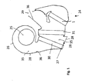
- Fig. 1 shows an automotive air conditioning 24.
- an air conditioning case 26 having a bottom wall 27 and an outlet portion 29, a fan 25, an air filter 30, a refrigerant evaporator 31 and a heat exchanger 1 is arranged as an electric heater.
- the air conditioning housing 26 thus forms a channel 35 for passing the air.
- Walls 28 of the air conditioning housing 26 have on the inside a surface 36 which define the channel 35.
- the air for the interior of a motor vehicle is passed by means of the blower 25 through the air filter 30, the refrigerant evaporator 31 and the heat exchanger 1.
- the automotive air conditioning system 24 is thus not provided with a heat exchanger through which coolant flows for heating the air conducted through the motor vehicle installation 24.
- the air conducted by the motor vehicle air conditioning system 24 is electrically heated exclusively by means of the heat exchanger 1.
- the motor vehicle air conditioning system 24 is preferably in a motor vehicle with only electric drive or with a Hybrid drive used (not shown).
- the heat exchanger with high voltage eg. B. with more than 50 volts, for example, 60 V or 600 V, operated in order not to get too high currents and thus too thick power lines (not shown).
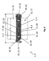
- FIG. 1 to 8 a first embodiment of the heat exchanger 1 for the motor vehicle air conditioner 24 is shown.
- An aluminum tube 18 designed as a flat tube 13 has two broad side walls 20 and two narrow side walls 21 (FIG. Fig. 2 and 6 ) on.
- the width and narrow side walls 20, 21 thereby represent cavity walls 17, which enclose a cavity 19 within the tube 18.
- a narrow side wall 21 is connected to each other by means of a tongue and groove connection 15.
- two molded seals 23 are arranged as electrical insulating elements 22.
- the two form seals 23 are made of elastic silicone and each have a recess 14 on one side.
- two conductors 4 namely a first printed circuit board 6 and a second printed circuit board 7 are arranged.
- PTC elements 3 designed as electrical resistance heating elements 2 are arranged between the two circuit boards 6, 7.
- the PTC elements 3 are connected to each other with the two printed circuit boards 6, 7 with adhesive.
- the two form seals 23 each have a slot 16 (FIG. Fig. 2 ), through which in each case an electrical contact plate 5 of the circuit board 6, 7 is guided.
- the two printed circuit boards 6, 7 are thus completely enclosed by the two molded seals 23, because the molded seals 23 on the edges outside of the recess 14 lie directly on one another and thereby also seal due to their elastic properties.
- the electrical contacting of the two circuit boards 6, 7 takes place by means of unillustrated electrical lines to the contact plates 5.
- the two circuit boards 6, 7 with the three PTC elements 10 thereby constitute a heating unit 10.
- a heating coil 9 or the heat exchanger 1 is present.
- Several heater 9 as shown in FIG Fig. 4 can also be connected to a heat exchanger 1 with a larger number of heating registers 9 to each other ( Fig. 3 to 5 ).
- the manufacturing steps for arranging the Wienverbundes 8 in the flat tubes 13 are in the Fig. 7 to 9 shown.
- the flat tubes 13 are connected to the corrugated fins 12 by means of soldering in a brazing furnace.
- a spacer (not shown) is introduced into the tongue and groove joint 15 during soldering, so that the flat tubes 13 are not soldered to one another at the tongue and groove connection 15, that is, they are not materially connected to one another , become.
- the flat tubes 13 are opened in the region of the tongue and groove joint 15, so that the flat tubes 13 deform in the region of the lower narrow side walls 21, in particular bend.
- the opening of the flat tubes 13 with the corrugated fins 12 takes place accordion-like according to the illustration of Fig. 7 to Fig. 8 ,
- the heating composites 8 in the direction of the tube depth, ie perpendicular to a plane of the drawing Fig. 8 perpendicular longitudinal axis of the tube 18, are inserted into the flat tubes 13.
- the flat tubes 13 are again connected to each other at the tongue and groove joint 15 and by means of compression of the tongue and groove joint 15 is a permanent attachment of the tongue and groove joint 15.
- the molded seals 23 are made of silicone and elastic deformable and while the size of the molded gaskets 23 is matched to the heating unit 10 to the effect that the heating composite 8 is slightly larger than the closed flat tube 13.
- the mold seals 23 are elastically deformed and biased when closing the tongue and groove joints 15, so that characterized the heating composite 8 under bias between the cavity walls 17 of the flat tube 13, in particular between the broad side walls 20, the flat tube 13 is clamped and thus non-positively connected to the flat tube 13.
- a correspondingly directed force F is applied to the wide side walls 20 ( Fig. 9 ).
- the net height H N of the heat exchanger 1 as shown in FIG Fig. 4 is about 50 to 300 mm, preferably 100 to 200 mm and the mesh width B N is about 50 to 300 mm, preferably 100 to 200 mm.
- the transverse division Q ie the distance between the flat tubes 13 as shown in FIG Fig. 5 , is in this case between 5 and 30 mm, preferably 9 to 18 mm and the net depth T N as shown in FIG Fig. 5 is 6 to 60 mm, preferably 10 to 40 mm.
- the cavity 19 enclosed by the cavity walls of the flat tube 13 is a void 32 in the area of the narrow side walls 21, ie in the void 32 only air ( Fig. 6 ). Deviating from this, in the empty spaces 32 as shown in FIG Fig. 6
- the molded gasket 23 may also be arranged with a corresponding other geometric design of the molded gasket 23 (FIG. Fig. 8 ).
- the flat tube 13 has no tongue and groove connection 15, but comprises two wide side walls 20 and only one narrow side wall 21. As a result, the flat tube 13 has an opening 34.
- the mushroom-shaped thickening 33 is arranged in a correspondingly complementary thereto aligned geometry of the flat tube 13, so that in addition to a non-positive connection and a positive connection between the heating system 8 and the flat tube 13 is possible.
- the two form seals 23 In the in Fig. 12 illustrated embodiment of the two form seals 23, these have a tongue and groove connection 37. By means of the tongue and groove connection 37, the two form seals 23 are interconnected.
- the arrangement of the heating unit 10 in the recesses 14 of the two form seals 23 corresponds to the training in Fig. 11 .
- the introduction of the heating system 8 in the flat tubes 13 takes place in accordance with the second embodiment 10 to 12 in an analogous manner as in the first embodiment according to Fig. 2 to 9 That is, the flat tubes 13 are bent and opened in the region of the openings 34 and then in each case a heating composite 8 is inserted into the flat tube 13 in the direction of the tube depth. Subsequently, the Breitagonistwandept 20 are back to the position shown in FIG Fig. 11 brought.
- the two form seals 23 preferably have a gap S1 and S2.
- the two printed circuit boards 6, 7 with the interposed PCT elements 3 can be electrically isolated with the molded seals 23 in a simple manner and also be sealed fluid-tight within the heat exchanger 1.
- the heat exchanger 1 with the electrical resistance heating elements 2 can also be used with high voltage, ie with voltages of 60 V or 300 V in motor vehicle air conditioning systems 24.
- dirt or moisture do not cause damage to the heat exchanger 1, because the conductors 4 are arranged with the PTC elements 3 fluid-tight within the two mold seals 23.
Landscapes
- Physics & Mathematics (AREA)
- Thermal Sciences (AREA)
- Engineering & Computer Science (AREA)
- Mechanical Engineering (AREA)
- Air-Conditioning For Vehicles (AREA)
Abstract
Description
- Die Erfindung betrifft einen Wärmeübertrager gemäß dem Oberbegriff des Anspruches 1, eine Kraftfahrzeugklimaanlage gemäß dem Oberbegriff des Anspruches 10 und ein Verfahren zur Herstellung eines Wärmeübertragers oder einer Kraftfahrzeugklimaanlage gemäß dem Oberbegriff des Anspruches 11.
- Kraftfahrzeugklimaanlagen dienen dazu, die dem Innenraum eines Kraftfahrzeuges zuzuführende Luft zu erwärmen und/oder zu kühlen. In Kraftfahrzeugklimaanlagen werden Wärmeübertrager als elektrische Heizeinrichtungen eingesetzt, um die Luft zu erwärmen, welche dem Innenraum zugeführt wird. Die elektrische Heizeinrichtung umfasst PTC-Elemente. PTC-Elemente (PTC: Positive Temperature Coefficient) sind Strom leitende Materialien, die einen elektrischen Widerstand aufweisen und bei tieferen Temperaturen den Strom besser leiten können als bei höheren Temperaturen. Ihr elektrischer Widerstand vergrößert sich somit bei steigender Temperatur. Das PTC-Element besteht im Allgemeinen aus Keramik und ist ein Kaltleiter. Dadurch stellt sich unabhängig von den Randbedingungen - wie z. B. angelegte Spannung, Nominalwiderstand oder Luftmenge an dem PTC-Element - eine sehr gleichmäßige Oberflächentemperatur am PTC-Element ein. Eine Überhitzung kann verhindert werden wie sie z. B. mit einem normalen Wärme abgebenden Heizdraht auftreten könnte, da hier unabhängig von den Randbedingungen immer ungefähr der gleiche Widerstand und dadurch eine im Wesentlichen identische elektrische Heizleistung aufgebracht wird.
- Der Wärmeübertrager umfasst PTC-Elemente, wenigstens zwei elektrische Leiter mittels denen elektrischer Strom durch das PTC-Element geleitet wird und Wärmeleitelemente, insbesondere Lamellen bzw. Wellrippen, mittels denen die Oberfläche zum Erwärmen der Luft vergrößert wird. In zunehmenden Maße werden Kraftfahrzeuge hergestellt, welche über einen ausschließlichen elektrischen Antrieb oder über einen Hybridantrieb verfügen. Kraftfahrzeugklimaanlagen für diese Kraftfahrzeuge verfügen im Allgemeinen nicht mehr über einen Wärmeaustauscher zum Erwärmen der Luft, der von Kühlflüssigkeit durchströmt wird. Die gesamte Heizleistung der Kraftfahrzeugklimaanlage muss deshalb von der elektrischen Heizeinrichtung bzw. den PTC-Elementen aufgebracht werden. Aus diesem Grund ist es erforderlich, die PTC-Elemente auch mit Hochspannung, z. B. im Bereich von 50 bis 600 Volt anstelle von Niederspannung mit 12 Volt, zu betreiben. Hochspannung in einer Kraftfahrzeugklimaanlage stellt jedoch ein Sicherheitsproblem dar, weil beispielsweise durch eine menschliche Berührung von unter Hochspannung stehenden Teilen dem Menschen von der Hochspannung gesundheitlicher Schaden zugefügt werden kann.
- Die
US 4 327 282 zeigt einen Wärmeübertrager mit einem PTC-Heizelement. Mittels Kontaktplatten wird Strom durch das PTC-Heizelement geleitet und an den Kontaktplatten ist eine Isolierschicht angeordnet. Die Komponenten werden mittels eines U-förmigen Clipses zusammengehalten. - Aus der
EP 1 768 458 A1 ist ein Wärme erzeugendes Element einer Heizvorrichtung zur Lufterwärmung bekannt, umfassend wenigstens ein PTC-Element und an gegenüberliegenden Seitenflächen des PTC-Elementes anliegende elektrische Leiterbahnen, wobei die beiden elektrischen Leiterbahnen außenseitig von einer nicht elektrisch leitenden Isolierschicht umgeben sind. - Die Aufgabe der vorliegenden Erfindung besteht deshalb darin, einen Wärmeübertrager und eine Kraftfahrzeugklimaanlage sowie ein Verfahren zur Herstellung eines Wärmeübertragers und einer Kraftfahrzeugklimaanlage zur Verfügung zu stellen, bei dem ein mit elektrischen Strom unter Hochspannung, z. B. mehr als 50 V, betriebener Wärmeübertrager ohne Gefährdung für die Umwelt, insbesondere Menschen, betrieben werden kann. Der Wärmeübertrager und die Kraftfahrzeugklimaanlage sollen in der Herstellung preiswert sein zuverlässig im Betrieb arbeiten.
- Diese Aufgabe wird gelöst mit einem Wärmeübertrager, umfassend wenigstens ein elektrisches Widerstandsheizelement, insbesondere wenigstens ein PTC-Element, wenigstens zwei mit dem wenigstens einen elektrischen Widerstandsheizelement elektrisch leitend verbundene Leiter, insbesondere Leiterplatten, um elektrischen Strom durch das wenigstens eine elektrische Widerstandsheizelement zu leiten und dadurch das elektrische Widerstandsheizelement zu erwärmen, wenigstens ein Wärmeleitelement zur Übertragung von Wärme von dem wenigstens einen elektrischen Widerstandsheizelement auf ein zu erwärmendes Fluid, wenigstens ein elektrisches Isolierelement, welches die wenigstens zwei Leiter elektrisch isoliert, vorzugsweise von dem wenigstens einen Wärmeleitelement, wobei die wenigstens zwei Leiter und/oder das wenigstens eine elektrische Widerstandsheizelement in wenigstens einem von wenigstens einer Hohlraumwandung begrenzten Hohlraum angeordnet sind und das wenigstens eine elektrische Isolierelement wenigstens eine Formdichtung ist, welche den Hohlraum dahingehend wenigstens teilweise ausfüllt, dass die wenigstens zwei Leiter und/oder das wenigstens eine elektrische Widerstandsheizelement elektrisch, vorzugsweise von der wenigstens einen Hohlraumwandung, wenigstens teilweise, insbesondere vollständig, isoliert sind. Die wenigstens eine Formdichtung besteht aus einem elektrisch isolierenden und thermisch leitfähigen Material. Aufgrund der geometrischen Anordnung der wenigstens einen Formdichtung innerhalb des Wärmeübertragers sind die wenigstens zwei Leiter und das wenigstens eine elektrische Widerstandsheizelement elektrisch isoliert. Die Formdichtung ist in einem festen Aggregatzustand, d. h. nicht flüssig oder gasförmig, auch bei hohen Temperaturen, z. B. 70°C oder 100°C.
- In einer ergänzenden Ausführungsform umfasst die wenigstens eine Hohlraumwandung in einem Querschnitt zwei Breitseitenwandungen und eine oder zwei Schmalseitenwandungen und/oder die wenigstens eine Hohlraumwandung bildet in einem Querschnitt ein geschlossenes Rohr, insbesondere Flachrohr. Ein geschlossenes Rohr ist ein Rohr, dessen Wandungen in einem Querschnitt vollständig geschlossen sind.
- In einer weiteren Ausführungsform umfasst das wenigstens eine Wärmeleitelement die wenigstens eine Hohlraumwandung und/oder das wenigstens eine Wärmeleitelement umfasst Wellrippen, welche außenseitig an der wenigstens einen Hohlraumwandung, insbesondere mittels Löten, angeordnet sind und/oder die wenigstens zwei Leiter weisen keinen unmittelbaren Kontakt zu der wenigstens einen Hohlraumwandung auf.
- In einer weiteren Ausgestaltung sind die Wellrippen und die wenigstens eine Hohlraumwandung mittels Kleben miteinander verbunden.
- In einer zusätzlichen Variante sind die Wellrippen und die wenigstens eine Hohlraumwandung, wobei vorzugsweise Hohlraumwandungen das Rohr bilden, in einem Rahmen eingespannt und dadurch miteinander verbunden.
- In einer ergänzenden Ausführungsform bestehen wenigstens ein Wärmeleitelement, insbesondere die wenigstens eine Hohlraumwandung und/oder die Wellrippen, wenigstens teilweise, insbesondere vollständig, aus Metall, beispielsweise Aluminium oder Stahl, oder Kunststoff.
- Vorzugsweise weist die wenigstens eine Formdichtung eine Aussparung zur Aufnahme des wenigstens einen Leiters auf
- In einer Variante sind in einem Hohlraum zwei Formdichtungen angeordnet und vorzugsweise sind die Formdichtungen zwischen einer Hohlraumwandung und einem Leiter angeordnet, so dass die wenigstens zwei Leiter bezüglich der Hohlraumwandung elektrisch isoliert sind und/oder die wenigstens zwei Leiter vollständig in den zwei Formdichtungen eingeschlossen sind. Die beiden Formdichtungen weisen entsprechend komplementär zueinander ausgerichtete Aussparungen auf, so dass beim Aufeinanderlegen der beiden Formdichtungen innerhalb der Formdichtungen ein ergänzender Aufnahmeraum entsteht. In diesen Aufnahmeraum sind die beiden Leiter mit den daran dazwischen angeordneten PTC-Elementen angeordnet. Dadurch sind die beiden Leiter vollständig innerhalb der beiden Formdichtungen angeordnet und lediglich die elektrischen Kontaktplatten reichen aus den Formdichtungen heraus zur elektrischen Kontaktierung. Die Kontaktplatten sind vorzugsweise nicht Bestandteil der Leiter, so dass die Leiter von den beiden Formdichtungen vollständig eingeschlossen sind.
- Zweckmäßig ist die wenigstens eine Formdichtung elastisch und/oder die wenigstens eine Formdichtung besteht wenigstens teilweise aus Silikon oder Kunststoff oder Gummi und/oder die wenigstens eine Formdichtung ist mit der wenigstens einen Hohlraumwandung kraft- und/oder form- und/oder stoffschlüssig verbunden. Aufgrund von elastischen Eigenschaften der wenigstens einen Formdichtung kann mittels einer elastischen Verformung der wenigstens einen Formdichtung die wenigstens eine Formdichtung innerhalb des Hohlraumes, d. h. zwischen den Hohlraumwandungen, eingespannt werden und damit kraftschlüssig verbunden.
- In einer weiteren Ausführungsform umfasst die wenigstens eine Formdichtung wärmeübertragende oder wärmeleitende Partikel, z. B. Aluminiumoxid und/oder Siliziumkarbid und/oder Bornitrid. Dadurch kann die Wärmeleitfähigkeit der wenigstens einen Formdichtung erhöht werden und trotzdem weist die wenigstens eine Formdichtung eine ausreichend große elektrische Isolation auf.
- Insbesondere sind wenigstens ein elektrisches Widerstandsheizelement, die wenigstens zwei Leiter und die wenigstens eine Formdichtung zu wenigstens einem Heizverbund verbunden, welches oder welche in dem wenigstens einen Hohlraum angeordnet ist oder sind.
- Eine erfindunsgemäße Kraftfahrzeugklimaanlage umfasst wenigstens einen in dieser Schutzrechtsanmeldung beschriebenen Wärmeübertrager.
- Erfindungsgemäßes Verfahren zur Herstellung eines Wärmeübertragers oder einer Kraftfahrzeugklimaanlage, insbesondere eines in dieser Schutzrechtsanmeldung beschriebenen Wärmeübertragers oder einer in dieser Schutzrechtsanmeldung beschriebenen Kraftfahrzeugklimaanlage, mit den Schritten: zur Verfügung stellen wenigstens eines elektrischen Widerstandsheizelementes, insbesondere wenigstens eines PTC-Elements, zur Verfügung stellen von wenigstens zwei elektrischen Leitern, insbesondere Leiterplatten, zum Durchleiten von elektrischen Strom durch das wenigstens eine elektrische Widerstandsheizelement, zur Verfügung stellen wenigstens eines Wärmeleitelements zur Übertragung von Wärme von dem wenigstens einen elektrischen Widerstandsheizelement auf ein zu erwärmende Fluid, zur Verfügung stellen wenigstens eines elektrischen Isolierelementes zum elektrischen Isolieren des wenigstens eine Wärmeleitelements von den wenigstens zwei Leitern, Verbinden der wenigstens zwei Leiter mit dem wenigstens einen elektrischen Widerstandsheizelement, thermisches Verbinden des wenigstens einen Wärmeleitelementes mit dem wenigstens einen Leiter und/oder mit dem wenigstens einen elektrischen Widerstandsheizelement, elektrisches Isolieren der wenigstens zwei Leiter, vorzugsweise von dem wenigstens einen Wärmeleitelement, mittels des wenigstens einen elektrischen Isolierelementes, wobei das wenigstens eine Wärmeleitelement wenigstens eine Hohlraumwandung umfasst, welche oder welches wenigstens einen Hohlraum einschließt und in den wenigstens einen Hohlraum die wenigstens zwei Leiter und/oder das wenigstens eine elektrische Widerstandsheizelement angeordnet werden und das wenigstens eine elektrisches Isolierelement wenigstens eine Formdichtung ist, welche in den wenigstens einen Hohlraum eingebracht wird, so dass die wenigstens zwei Leiter und/oder das wenigstens eine elektrische Widerstandsheizelement elektrisch, vorzugsweise von der wenigstens einen Hohlraumwandung, isoliert werden.
- In einer ergänzenden Variante werden die wenigstens zwei Leiter mit dem wenigstens einen elektrischen Widerstandsheizelement und der wenigstens einen Formdichtung zu wenigstens einem Heizverbund verbunden und anschließend wird der wenigstens eine Heizverbund in den wenigstens einen Hohlraum eingebracht.
- In einer weiteren Variante wird nach dem Einbringen des wenigstens einen Heizverbundes in den wenigstens einen Hohlraum die Form der wenigstens einen Hohlraumwandung verändert, insbesondere gebogen, so dass das Volumen des wenigstens einen Hohlraumes verkleinert wird und vorzugsweise dadurch der Heizverbund kraftschlüssig mit der wenigstens einen Hohlraumwandung verbunden wird.
- Vorzugsweise wird der Heizverbund dabei mittels einer elastischen Verformung der wenigstens einen Formdichtung kraftschlüssig mit der wenigstens einen Hohlraumwandung verbunden.
- In einer weiteren Ausgestaltung wird bei dem Verkleinern des Volumens des wenigstens einen Hohlraumes aufgrund eines Kontaktes zwischen der wenigstens einen Hohlraumwandung und der wenigstens einen Formdichtung die wenigstens eine Formdichtung elastisch verformt und durch die elastischen Kräfte der wenigstens einen Formdichtung wird nach der elastischen Verformung die wenigstens eine Formdichtung kraftschlüssig mit der wenigstens einen Hohlraumwandung verbunden, insbesondere wird die wenigstens eine Formdichtung zwischen zwei Hohlraumwänden eingeklemmt.
- Insbesondere sind die Geometrie der wenigstens einen Formdichtung und die Geometrie der wenigstens einen Hohlraumwandung dahingehend komplementär zueinander abgestimmt, dass der wenigstens eine Heizverbund nach dem Einbringen in den wenigstens einen Hohlraum mit der wenigstens einen Hohlraumwandung formschlüssig verbunden wird. Die Geometrie der wenigstens einen Formdichtung umfasst beispielsweise eine pilzförmige Verdickung und die wenigstens eine Hohlraumwandung ist entsprechend komplementär dazu ausgerichtet, so dass dadurch die wenigstens eine Formdichtung formschlüssig innerhalb der wenigstens einen Hohlraumwandung befestigbar ist oder verbunden wird.
- In einer weiteren Ausgestaltung weist das wenigstens eine Wärmeleitelement und/oder die wenigstens eine Formdichtung eine Wärmeleitfähigkeit von wenigstens 1 W/mK, insbesondere wenigstens 15 W/mK auf.
- In einer weiteren Ausführungsform weist die wenigstens eine Formdichtung eine elektrische Isolation von wenigstens 1 kV/mm, insbesondere wenigstens 25 kV/mm auf.
- In einer Variante weist die wenigstens eine Formdichtung, vorzugsweise im Querschnitt, eine Durchschlagfestigkeit von wenigstens 1 kV auf.
- In einer weiteren Ausgestaltung weist die wenigstens eine Formdichtung eine Wärmeleitfähigkeit von wenigstens 1 W/mK, insbesondere wenigstens 15 W/mK auf. Die wenigstens eine Formdichtung kann damit einerseits gut elektrisch isolieren und kann andererseits ausreichend gut die Wärme von dem elektrischen Widerstandsheizelement zu dem Wärmeleitelement oder den Wärmeleitelementen leiten.
- Im Nachfolgenden werden Ausführungsbeispiele der Erfindung unter Bezugnahme auf die beigefügten Zeichnungen näher beschrieben. Es zeigt:
- Fig. 1
- einen Querschnitt einer Kraftfahrzeugklimaanlage,
- Fig. 2
- eine Explosionsdarstellung eines Wärmeübertragers bzw. Heizregisters in einem ersten Ausführungsbeispiel,
- Fig. 3
- eine perspektivische Ansicht mehrerer Heizregister des Wärmeübertragers gemäß
Fig. 2 , - Fig. 4
- eine Seitenansicht des Wärmeübertragers gemäß
Fig. 3 , - Fig. 5
- eine Draufsicht des Wärmeübertragers gemäß
Fig. 3 , - Fig. 6
- einen Querschnitt des Heizregisters gemäß
Fig. 2 , - Fig. 7
- einen Querschnitt mehrerer Flachrohre,
- Fig. 8
- einen Querschnitt von drei Flachrohren und einem Heizverbund,
- Fig. 9
- einen Querschnitt des Flachrohres mit einem Heizverbund in dem Flachrohr als Heizregisters bzw. Wärmeübertrager,
- Fig. 10
- eine Explosionsdarstellung des Wärmeübertragers bzw. Heizregisters in einem zweiten Ausführungsbeispiel,
- Fig. 11
- einen Querschnitt des Heizregisters gemäß
Fig. 10 und - Fig. 12
- einen Querschnitt zweier Formdichtungen für das Heizregisters gemäß
Fig. 11 . -
Fig. 1 zeigt eine Kraftfahrzeugklimaanlage 24. In einem Klimaanlagengehäuse 26 mit einer Bodenwandung 27 und einem Austrittsabschnitt 29 ist ein Gebläse 25, ein Luftfilter 30, ein Kältemittelverdampfer 31 und ein Wärmeübertrager 1 als eine elektrische Heizeinrichtung angeordnet. Das Klimaanlagengehäuse 26 bildet somit einen Kanal 35 zum Durchleiten der Luft. Wandungen 28 des Klimaanlagengehäuses 26 weisen an der Innenseite eine Oberfläche 36 auf, welche den Kanal 35 begrenzen. Die Luft für den Innenraum eines Kraftfahrzeuges wird mittels des Gebläses 25 durch den Luftfilter 30, den Kältemittelverdampfer 31 sowie den Wärmeübertrager 1 geleitet. - Die Kraftfahrzeugklimaanlage 24 ist somit nicht mit einem von Kühlmittel durchströmten Wärmeaustauscher versehen zum Erwärmen der durch die Kraftfahrzeuganlage 24 geleiteten Luft. Die durch die Kraftfahrzeugklimaanlage 24 geleitete Luft wird ausschließlich mittels des Wärmeübertrager 1 elektrisch erwärmt. Die Kraftfahrzeugklimaanlage 24 wird vorzugsweise in einem Kraftfahrzeug mit ausschließlich elektrischem Antrieb oder mit einem Hybridantrieb eingesetzt (nicht dargestellt). Um mittels des Wärmeübertragers 1 die notwendige elektrische Heizleistung zu erreichen, muss der Wärmeübertrager mit Hochspannung, z. B. mit mehr als 50 Volt, beispielsweise mit 60 V oder 600 V, betrieben werden, um keine zu großen Stromstärken und damit zu dicke Stromleitungen (nicht dargestellt) zu erhalten.
- In den
Fig. 1 bis 8 ist ein erstes Ausführungsbeispiel des Wärmeübertragers 1 für die Kraftfahrzeugklimaanlage 24 dargestellt. Ein als Flachrohr 13 ausgebildetes Rohr 18 aus Aluminium weist zwei Breitseitenwandungen 20 und zwei Schmalseitenwandungen 21 (Fig. 2 und6 ) auf. Die Breiten- und Schmalseitenwandungen 20, 21 stellen dabei Hohlraumwandungen 17 dar, welche einen Hohlraum 19 innerhalb des Rohres 18 einschließen. Eine Schmalseitenwandung 21 ist dabei mittels einer Nut-Feder-Verbindung 15 miteinander verbunden. Innerhalb des Flachrohres 13 sind zwei Formdichtungen 23 als elektrische Isolierelemente 22 angeordnet. Die beiden Formdichtungen 23 bestehen dabei aus elastischem Silikon und weisen an einer Seite jeweils eine Aussparung 14 auf. Innerhalb dieser beiden Aussparungen 14 der beiden Formdichtungen 23, die beim Aufeinanderliegen der beiden Formdichtungen 23 dabei einen Aufnahmehohlraum ausbilden, sind zwei Leiter 4, nämlich eine erste Leiterplatte 6 und eine zweite Leiterplatte 7 angeordnet. Zwischen den beiden Leiterplatten 6, 7 sind drei als PTC-Elemente 3 ausgebildete elektrische Widerstandsheizelemente 2 angeordnet. Die PTC-Elemente 3 sind dabei mit den beiden Leiterplatten 6, 7 mit Klebstoff miteinander verbunden. Die beiden Formdichtungen 23 weisen dabei jeweils einen Schlitz 16 (Fig. 2 ) auf, durch welche jeweils eine elektrische Kontaktplatte 5 der Leiterplatte 6, 7 geführt ist. - Die beiden Leiterplatten 6, 7 sind somit vollständig von den beiden Formdichtungen 23 eingeschlossen, weil die Formdichtungen 23 an den Rändern außerhalb der Aussparung 14 unmittelbar aufeinanderliegen und dabei aufgrund ihrer elastischen Eigenschaften auch abdichten. Dadurch sind die beiden Leiterplatten 6, 7 mit den dazwischen angeordneten drei PTC-Elementen 3 aufgrund der elektrischen Isolation der Formdichtungen 23 elektrisch isoliert und außerdem fluiddicht aufgrund der Dichtungseigenschaften der beiden aufeinanderliegenden Formdichtungen 23 abgeschlossen. Die elektrische Kontaktierung der beiden Leiterplatten 6, 7 erfolgt mittels nicht dargestellter elektrischer Leitungen an den Kontaktplatten 5. Die beiden Leiterplatten 6, 7 mit den drei PTC-Elementen 10 stellen dabei eine Heizeinheit 10 dar. Nach dem Umschließen der Heizeinheit 10 mit den beiden Formdichtungen 23 bilden diese einen Heizverbund 8. Nach dem Einbringen des Heizverbundes 8 in die Flachrohre 13 mit den Wellrippen 12 liegt ein Heizregister 9 bzw. der Wärmeübertrager 1 vor. Mehrere Heizregister 9 gemäß der Darstellung in
Fig. 4 können auch zu einem Wärmeübertrager 1 mit einer größeren Anzahl von Heizregistern 9 zueinander verbunden werden (Fig. 3 bis 5 ). - Die Herstellungsschritte zum Anordnen des Heizverbundes 8 in den Flachrohren 13 sind in den
Fig. 7 bis 9 dargestellt. Die Flachrohre 13 werden mit den Wellrippen 12 mittels Löten in einem Lötofen miteinander verbunden. Im Bereich der Nut-Feder-Verbindung 15 wird beim Löten ein Abstandshalter (nicht dargestellt) in die Nut-Feder-Verbindung 15 eingebracht, so dass an der Nut-Feder-Verbindung 15 die Flachrohre 13 nicht miteinander verlötet, d. h. nicht stoffschlüssig miteinander verbunden, werden. Nach dem Entfernen der nicht dargestellten Abstandshalter werden die Flachrohre 13 im Bereich der Nut-Feder-Verbindung 15 geöffnet, so dass sich die Flachrohre 13 im Bereich der unteren Schmalseitenwandungen 21 verformen, insbesondere verbiegen. Das Öffnen der Flachrohre 13 mit den Wellrippen 12 erfolgt dabei ziehharmonikaartig gemäß der Darstellung vonFig. 7 zuFig. 8 . In der inFig. 8 dargestellten geöffneten Lage des Flachrohres 13 können die Heizverbünde 8 in Richtung der Rohrtiefe, d. h. senkrecht zu einer auf der Zeichenebene vonFig. 8 senkrecht stehenden Längsachse des Rohres 18, in die Flachrohre 13 eingeschoben werden. Nach dem Einschieben des Heizverbundes 8 in die Flachrohre 13 werden die Flachrohre 13 wieder an der Nut-Feder-Verbindung 15 miteinander verbunden und mittels Verpressen der Nut-Feder-Verbindung 15 erfolgt eine dauerhafte Befestigung der Nut-Feder-Verbindung 15. Die Formdichtungen 23 sind aus Silikon und elastisch verformbar und dabei ist die Größe der Formdichtungen 23 mit der Heizeinheit 10 dahingehend abgestimmt, dass der Heizverbund 8 geringfügig größer ist als das geschlossene Flachrohr 13. Dadurch werden die Formdichtungen 23 beim Schließen der Nut-Feder-Verbindungen 15 elastisch verformt und vorgespannt, so dass dadurch der Heizverbund 8 unter Vorspannung zwischen den Hohlraumwandungen 17 des Flachrohres 13, insbesondere zwischen den Breitseitenwandungen 20 das Flachrohres 13 eingespannt ist und damit kraftschlüssig mit dem Flachrohr 13 verbunden ist. Hierzu wird auf die Breitseitenwandungen 20 eine entsprechend gerichtete Kraft F aufgebracht (Fig. 9 ). - Die Netzhöhe HN des Wärmeübertragers 1 gemäß der Darstellung in
Fig. 4 beträgt ca. 50 bis 300 mm, vorzugsweise 100 bis 200 mm und die Netzbreite BN beträgt ca. 50 bis 300 mm, vorzugsweise 100 bis 200 mm. Die Querteilung Q, d. h. der Abstand zwischen den Flachrohren 13 gemäß der Darstellung inFig. 5 , beträgt dabei zwischen 5 und 30 mm, vorzugsweise 9 bis 18 mm und die Netztiefe TN gemäß der Darstellung inFig. 5 beträgt 6 bis 60 mm, vorzugsweise 10 bis 40 mm. - Der von den Hohlraumwandungen des Flachrohres 13 eingeschlossenen Hohlraum 19 ist im Bereich der Schmalseitenwandungen 21 ein Leerraum 32, d. h. in dem Leerraum 32 ist lediglich Luft (
Fig. 6 ). Abweichend hiervon kann in den Leeräumen 32 gemäß der Darstellung inFig. 6 auch die Formdichtung 23 angeordnet sein bei einer entsprechenden anderen geometrischen Ausbildung der Formdichtung 23 (Fig. 8 ). - In den
Fig. 10 bis 12 ist ein zweites Ausführungsbeispiel des Wärmeübertragers 1 bzw. des Heizregisters 9 dargestellt. Im Nachfolgenden werden im Wesentlichen nur die Unterschiede zu dem ersten Ausführungsbeispiel gemäßFig. 2 bis 9 beschrieben. Das Flachrohr 13 weist keine Nut-Feder-Verbindung 15 auf, sondern umfasst zwei Breitseitenwandungen 20 und nur eine Schmalseitenwandung 21. Dadurch weist das Flachrohr 13 eine Öffnung 34 auf. Die beiden Formdichtungen 23, welche aufeinanderliegen und in deren Aussparung 14 die Heizeinheit 10 angeordnet ist, weist dabei an zwei Enden gemäß dem Schnitt inFig. 11 und12 eine pilzförmige Verdickung 33 auf. Die pilzförmige Verdickung 33 ist dabei in einer entsprechend komplementär dazu ausgerichteten Geometrie des Flachrohres 13 angeordnet, so dass dadurch neben einer kraftschlüssigen Verbindung auch eine formschlüssige Verbindung zwischen dem Heizverbund 8 und dem Flachrohr 13 möglich ist. - In dem in
Fig. 12 dargestellten Ausführungsbeispiel der beiden Formdichtungen 23 weisen diese eine Nut-Feder-Verbindung 37 auf. Mittels der Nut-Feder-Verbindung 37 sind die beiden Formdichtungen 23 miteinander verbunden. Die Anordnung der Heizeinheit 10 in den Aussparungen 14 der beiden Formdichtungen 23 entspricht dabei der Ausbildung inFig. 11 . Das Einbringen des Heizverbundes 8 in die Flachrohre 13 erfolgt dabei im zweiten Ausführungsbeispiel gemäßFig. 10 bis 12 in analoger Weise wie im ersten Ausführungsbeispiel gemäßFig. 2 bis 9 , d. h. die Flachrohre 13 werden im Bereich der Öffnungen 34 aufgebogen und geöffnet und anschließend wird jeweils ein Heizverbund 8 in Richtung der Rohrtiefe in das Flachrohr 13 eingeschoben. Anschließend werden die Breitseitenwandungen 20 wieder in die Lage gemäß der Darstellung inFig. 11 gebracht. Die beiden Formdichtungen 23 weisen vorzugsweise einen Spalt S1 und S2 auf. - Insgesamt betrachtet sind mit dem erfindungsgemäßen Wärmeübertrager 1 und der erfindungsgemäßen Kraftfahrzeugklimaanlage 24 wesentliche Vorteile verbunden. Die beiden Leiterplatten 6, 7 mit den dazwischen angeordneten PCT-Elementen 3 können mit den Formdichtungen 23 auf einfache Art und Weise elektrisch isoliert und außerdem auch fluiddicht innerhalb des Wärmeübertragers 1 abgedichtet werden. Dadurch kann der Wärmeübertrager 1 mit den elektrischen Widerstandsheizelementen 2 auch mit Hochspannung, d. h. mit Spannungen von 60 V oder 300 V in Kraftfahrzeugklimaanlagen 24 eingesetzt werden. Auch Verschmutzungen oder Feuchtigkeit führen an dem Wärmeübertrager 1 nicht zu einem Schaden, weil die Leiter 4 mit den PTC-Elementen 3 fluiddicht innerhalb der beiden Formdichtungen 23 angeordnet sind.
Claims (15)
- Wärmeübertrager (1), umfassend- wenigstens ein elektrisches Widerstandsheizelement (2), insbesondere wenigstens ein PTC-Element (3),- wenigstens zwei mit dem wenigstens einen elektrischen Widerstandsheizelement (2) elektrisch leitend verbundene Leiter (4), insbesondere Leiterplatten (6, 7), um elektrischen Strom durch das wenigstens eine elektrische Widerstandsheizelement (2) zu leiten und dadurch das elektrische Widerstandsheizelement (2) zu erwärmen,- wenigstens ein Wärmeleitelement (11) zur Übertragung von Wärme von dem wenigstens einen elektrischen Widerstandsheizelement (2) auf ein zu erwärmendes Fluid,- wenigstens ein elektrisches Isolierelement (22), welches die wenigstens zwei Leiter (4) elektrisch isoliert, vorzugsweise von dem wenigstens einen Wärmeleitelement (11),
dadurch gekennzeichnet, dass
die wenigstens zwei Leiter (4) und/oder das wenigstens eine elektrische Widerstandsheizelement (2) in wenigstens einem von wenigstens einer Hohlraumwandung (17) begrenzten Hohlraum (19) angeordnet sind und das wenigstens eine elektrische Isolierelement (22) wenigstens eine Formdichtung (23) ist, welche den Hohlraum (19) dahingehend wenigstens teilweise ausfüllt, dass die wenigstens zwei Leiter (4) und/oder das wenigstens eine elektrische Widerstandsheizelement (2) elektrisch, vorzugsweise von der wenigstens einen Hohlraumwandung (17), wenigstens teilweise isoliert sind. - Wärmeübertrager nach Anspruch 1, dadurch gekennzeichnet, dass die wenigstens eine Hohlraumwandung (17) in einem Querschnitt zwei Breitseitenwandungen (20) und eine oder zwei Schmalseitenwandungen (21) umfasst und/oder die wenigstens eine Hohlraumwandung (17) in einem Querschnitt ein geschlossenes Rohr (18), insbesondere Flachrohr (13), bildet.
- Wärmeübertrager nach Anspruch 1 oder 2, dadurch gekennzeichnet, dass das wenigstens eine Wärmeleitelement (11) die wenigstens eine Hohlraumwandung (17) umfasst und/oder das wenigstens eine Wärmeleitelement (11) Wellrippen (12) umfasst, welche außenseitig an der wenigstens einen Hohlraumwandung (17), insbesondere mittels Löten, angeordnet sind und/oder die wenigstens zwei Leiter (4) keinen unmittelbaren Kontakt zu der wenigstens einen Hohlraumwandung (17) aufweisen.
- Wärmeübertrager nach einem oder mehreren der vorhergehenden Ansprüche, dadurch gekennzeichnet, dass das wenigstens eine Wärmeleitelement (11), insbesondere die wenigstens eine Hohlraumwandung (17) und/oder die Wellrippen (12), wenigstens teilweise, insbesondere vollständig, aus Metall, beispielsweise Aluminium oder Stahl, oder Kunststoff bestehen.
- Wärmeübertrager nach einem oder mehreren der vorhergehenden Ansprüche, dadurch gekennzeichnet, dass die wenigstens eine Formdichtung (23) eine Aussparung (14) zur Aufnahme des wenigstens einen Leiters (4) aufweist.
- Wärmeübertrager nach einem oder mehreren der vorhergehenden Ansprüche, dadurch gekennzeichnet, dass in einem Hohlraum (19) zwei Formdichtungen (23) angeordnet sind und vorzugsweise die Formdichtungen (23) zwischen einer Hohlraumwandung (17) und einem Leiter (4) angeordnet sind, so dass die wenigstens zwei Leiter (4) bezüglich der Hohlraumwandung (17) elektrisch isoliert sind und/oder die wenigstens zwei Leiter (4) vollständig in den zwei Formdichtungen (23) eingeschlossen ist.
- Wärmeübertrager nach einem oder mehreren der vorhergehenden Ansprüche, dadurch gekennzeichnet, dass die wenigstens eine Formdichtung (23) elastisch ist und/oder die wenigstens eine Formdichtung (23) wenigstens teilweise aus Silikon oder Kunststoff oder Gummi besteht und/oder die wenigstens eine Formdichtung (23) mit der wenigstens einen Hohlraumwandung (17) kraft- und/oder form-und/oder stoffschlüssig verbunden ist.
- Wärmeübertrager nach einem oder mehreren der vorhergehenden Ansprüchen, dadurch gekennzeichnet, dass die wenigstens eine Formdichtung (23) wärmeübertragende oder wärmeleitende Partikel, z. B. Aluminiumoxid und/oder Siliziumkarbid und/oder Bornitrid, umfasst.
- Wärmeübertrager nach einem oder mehreren der vorhergehenden Ansprüche, dadurch gekennzeichnet, dass das wenigstens eine elektrische Widerstandsheizelement (2), die wenigstens zwei Leiter (4) und die wenigstens eine Formdichtung (23) zu wenigstens einem Heizverbund (8) verbunden sind, welches oder welche in dem wenigstens einen Hohlraum (19) angeordnet ist oder sind.
- Kraftfahrzeugklimaanlage (24), dadurch gekennzeichnet, dass die Kraftfahrzeugklimaanlage (24) wenigstens einen Wärmeübertrager (1) gemäß einem oder mehrerer der vorhergehenden Ansprüche umfasst.
- Verfahren zur Herstellung eines Wärmeübertragers (1) oder einer Kraftfahrzeugklimaanlage (24), insbesondere eines Wärmeübertragers (1) gemäß einem oder mehrerer der Ansprüche 1 bis 9 oder einer Kraftfahrzeugklimaanlage (24) gemäß Anspruch 10, mit den Schritten:- zur Verfügung stellen wenigstens eines elektrischen Widerstandsheizelementes (2), insbesondere wenigstens eines PTC-Elements (3),- zur Verfügung stellen von wenigstens zwei elektrischen Leitern (4), insbesondere Leiterplatten (6, 7), zum Durchleiten von elektrischen Strom durch das wenigstens eine elektrische Widerstandsheizelement (2),- zur Verfügung stellen wenigstens eines Wärmeleitelements (11) zur Übertragung von Wärme von dem wenigstens einen elektrischen Widerstandsheizelement (2) auf ein zu erwärmende Fluid,- zur Verfügung stellen wenigstens eines elektrischen Isolierelementes (22) zum elektrischen Isolieren des wenigstens eine Wärmeleitelements (11) von den wenigstens zwei Leitern (4),- Verbinden der wenigstens zwei Leiter (4) mit dem wenigstens einen elektrischen Widerstandsheizelement (2),- thermisches Verbinden des wenigstens einen Wärmeleitelementes (11) mit dem wenigstens einen Leiter (4) und/oder mit dem wenigstens einen elektrischen Widerstandsheizelement (2),- elektrisches Isolieren der wenigstens zwei Leiter (4), vorzugsweise von dem wenigstens einen Wärmeleitelement (11), mittels des wenigstens einen elektrischen Isolierelementes (22),
dadurch gekennzeichnet, dass
das wenigstens eine Wärmeleitelement (11) wenigstens eine Hohlraumwandung (17) umfasst, welche oder welches wenigstens einen Hohlraum (19) einschließt und in den wenigstens einen Hohlraum (19) die wenigstens zwei Leiter (4) und/oder das wenigstens eine elektrische Widerstandsheizelement (2) angeordnet werden und das wenigstens eine elektrisches Isolierelement (22) wenigstens eine Formdichtung (23) ist, welche in den wenigstens einen Hohlraum (19) eingebracht wird, so dass die wenigstens zwei Leiter (4) und/oder das wenigstens eine elektrische Widerstandsheizelement (2) elektrisch, vorzugsweise von der wenigstens einen Hohlraumwandung (17), isoliert werden. - Verfahren nach Anspruch 11, dadurch gekennzeichnet, dass die wenigstens zwei Leiter (4) mit dem wenigstens einen elektrischen Widerstandsheizelement (2) und der wenigstens einen Formdichtung (23) zu wenigstens einem Heizverbund (8) verbunden werden und anschließend der wenigstens eine Heizverbund (8) in den wenigstens einen Hohlraum (19) eingebracht wird.
- Verfahren nach Anspruch 12, dadurch gekennzeichnet, dass nach dem Einbringen des wenigstens einen Heizverbundes (8) in den wenigstens einen Hohlraum (19) die Form der wenigstens einen Hohlraumwandung (17) verändert wird, insbesondere gebogen wird, so dass das Volumen des wenigstens einen Hohlraumes (19) verkleinert wird und vorzugsweise dadurch der Heizverbund (8) kraftschlüssig mit der wenigstens einen Hohlraumwandung (17) verbunden wird.
- Verfahren nach Anspruch 13, dadurch gekennzeichnet, dass bei dem Verkleinern des Volumens des wenigstens einen Hohlraumes (19) aufgrund eines Kontaktes zwischen der wenigstens einen Hohlraumwandung (17) und der wenigstens einen Formdichtung (23) die wenigstens eine Formdichtung (23) elastisch verformt wird und durch die elastischen Kräfte der wenigstens einen Formdichtung (23) nach der elastischen Verformung die wenigstens eine Formdichtung (23) kraftschlüssig mit der wenigstens einen Hohlraumwandung (17) verbunden wird, insbesondere die wenigstens eine Formdichtung (23) zwischen zwei Hohlraumwänden (17) eingeklemmt wird.
- Verfahren nach Anspruch 13 oder 14, dadurch gekennzeichnet, dass die Geometrie der wenigstens einen Formdichtung (23) und die Geometrie der wenigstens einen Hohlraumwandung (17) dahingehend komplementär zueinander abgestimmt sind, dass der wenigstens eine Heizverbund (8) nach dem Einbringen in den wenigstens einen Hohlraum (19) mit der wenigstens einen Hohlraumwandung (17) formschlüssig verbunden wird.
Priority Applications (1)
| Application Number | Priority Date | Filing Date | Title |
|---|---|---|---|
| EP10290021.4A EP2346304B1 (de) | 2010-01-15 | 2010-01-15 | Wärmeübertrager |
Applications Claiming Priority (1)
| Application Number | Priority Date | Filing Date | Title |
|---|---|---|---|
| EP10290021.4A EP2346304B1 (de) | 2010-01-15 | 2010-01-15 | Wärmeübertrager |
Publications (2)
| Publication Number | Publication Date |
|---|---|
| EP2346304A1 true EP2346304A1 (de) | 2011-07-20 |
| EP2346304B1 EP2346304B1 (de) | 2016-06-15 |
Family
ID=42144771
Family Applications (1)
| Application Number | Title | Priority Date | Filing Date |
|---|---|---|---|
| EP10290021.4A Revoked EP2346304B1 (de) | 2010-01-15 | 2010-01-15 | Wärmeübertrager |
Country Status (1)
| Country | Link |
|---|---|
| EP (1) | EP2346304B1 (de) |
Cited By (6)
| Publication number | Priority date | Publication date | Assignee | Title |
|---|---|---|---|---|
| EP2793241A1 (de) * | 2013-04-18 | 2014-10-22 | Behr France Rouffach SAS | PTC-Vorrichtung |
| WO2017080824A1 (de) * | 2015-11-12 | 2017-05-18 | Robert Bosch Gmbh | Verfahren zur herstellung einer elektrischen heizung |
| EP3255369A1 (de) * | 2016-06-08 | 2017-12-13 | Mahle International GmbH | Rippenelement für einen wärmeübertrager |
| DE102017223785A1 (de) * | 2017-12-22 | 2019-06-27 | Eberspächer Catem Gmbh & Co. Kg | Verfahren zur Herstellung eines wärmeerzeugenden Elementes |
| CN110065358A (zh) * | 2018-01-22 | 2019-07-30 | 福特全球技术公司 | 特别用于加热车辆的内部空间和/或车辆的机组的温度控制装置 |
| EP4333558A1 (de) * | 2022-08-31 | 2024-03-06 | MAHLE International GmbH | Ptc-heizung und verfahren |
Citations (7)
| Publication number | Priority date | Publication date | Assignee | Title |
|---|---|---|---|---|
| US4327282A (en) | 1978-10-21 | 1982-04-27 | Firma Fritz Eichenauer | Electrical resistance heating element |
| EP0307217A1 (de) * | 1987-09-11 | 1989-03-15 | Murata Manufacturing Co., Ltd. | Kaltleiterthermistor-Vorrichtung für Heizgeräte |
| US4972067A (en) * | 1989-06-21 | 1990-11-20 | Process Technology Inc. | PTC heater assembly and a method of manufacturing the heater assembly |
| FR2826829A1 (fr) * | 2001-06-27 | 2003-01-03 | Valeo Climatisation | Echangeur de chaleur a barreaux chauffants contenant des elements resistifs |
| EP1528838A2 (de) * | 2003-11-03 | 2005-05-04 | Delphi Technologies, Inc. | Elektrisches Heizelement |
| EP1768458A1 (de) | 2005-09-23 | 2007-03-28 | Catem GmbH & Co.KG | Wärmeerzeugendes Element einer Heizvorrichtung |
| US20080173637A1 (en) * | 2005-11-02 | 2008-07-24 | Koshiro Taguchi | Insulated waterproof heater |
Family Cites Families (3)
| Publication number | Priority date | Publication date | Assignee | Title |
|---|---|---|---|---|
| US4037082A (en) | 1976-04-30 | 1977-07-19 | Murata Manufacturing Co., Ltd. | Positive temperature coefficient semiconductor heating device |
| US5198640A (en) | 1991-05-28 | 1993-03-30 | Yang Chiung Hsiang | Fully clad electric ptc heater with a finned protective casing |
| ES2137114B1 (es) | 1997-08-01 | 2000-11-16 | Dbk Espana Sa | Dispositivo calefactor de tabletas o mechas para la vaporizacion de materias activas. |
-
2010
- 2010-01-15 EP EP10290021.4A patent/EP2346304B1/de not_active Revoked
Patent Citations (7)
| Publication number | Priority date | Publication date | Assignee | Title |
|---|---|---|---|---|
| US4327282A (en) | 1978-10-21 | 1982-04-27 | Firma Fritz Eichenauer | Electrical resistance heating element |
| EP0307217A1 (de) * | 1987-09-11 | 1989-03-15 | Murata Manufacturing Co., Ltd. | Kaltleiterthermistor-Vorrichtung für Heizgeräte |
| US4972067A (en) * | 1989-06-21 | 1990-11-20 | Process Technology Inc. | PTC heater assembly and a method of manufacturing the heater assembly |
| FR2826829A1 (fr) * | 2001-06-27 | 2003-01-03 | Valeo Climatisation | Echangeur de chaleur a barreaux chauffants contenant des elements resistifs |
| EP1528838A2 (de) * | 2003-11-03 | 2005-05-04 | Delphi Technologies, Inc. | Elektrisches Heizelement |
| EP1768458A1 (de) | 2005-09-23 | 2007-03-28 | Catem GmbH & Co.KG | Wärmeerzeugendes Element einer Heizvorrichtung |
| US20080173637A1 (en) * | 2005-11-02 | 2008-07-24 | Koshiro Taguchi | Insulated waterproof heater |
Cited By (8)
| Publication number | Priority date | Publication date | Assignee | Title |
|---|---|---|---|---|
| EP2793241A1 (de) * | 2013-04-18 | 2014-10-22 | Behr France Rouffach SAS | PTC-Vorrichtung |
| WO2017080824A1 (de) * | 2015-11-12 | 2017-05-18 | Robert Bosch Gmbh | Verfahren zur herstellung einer elektrischen heizung |
| KR20180081564A (ko) * | 2015-11-12 | 2018-07-16 | 로베르트 보쉬 게엠베하 | 전기 히터의 제조 방법 |
| EP3255369A1 (de) * | 2016-06-08 | 2017-12-13 | Mahle International GmbH | Rippenelement für einen wärmeübertrager |
| DE102017223785A1 (de) * | 2017-12-22 | 2019-06-27 | Eberspächer Catem Gmbh & Co. Kg | Verfahren zur Herstellung eines wärmeerzeugenden Elementes |
| CN109963361A (zh) * | 2017-12-22 | 2019-07-02 | 埃贝赫卡腾有限两合公司 | 制造热生成元件的方法 |
| CN110065358A (zh) * | 2018-01-22 | 2019-07-30 | 福特全球技术公司 | 特别用于加热车辆的内部空间和/或车辆的机组的温度控制装置 |
| EP4333558A1 (de) * | 2022-08-31 | 2024-03-06 | MAHLE International GmbH | Ptc-heizung und verfahren |
Also Published As
| Publication number | Publication date |
|---|---|
| EP2346304B1 (de) | 2016-06-15 |
Similar Documents
| Publication | Publication Date | Title |
|---|---|---|
| DE102011077922B4 (de) | Wärmeübertrager | |
| EP2428746B1 (de) | Wärmeübertrager | |
| EP2395295B1 (de) | Wärmeübertrager | |
| EP2190256B1 (de) | Wärmeübertrager | |
| EP2211590B1 (de) | Wärmeübertrager | |
| EP2428747B1 (de) | Wärmeübertrager | |
| EP2668450A1 (de) | Wärmeübertrager | |
| EP2346304B1 (de) | Wärmeübertrager | |
| EP2608632A1 (de) | Elektrische Heizvorrichtung und Rahmen hierfür | |
| EP2109345A1 (de) | Wärmeerzeugendes Element und Heizvorrichtung umfassend ein wärmeerzeugendes Element | |
| EP2395296B1 (de) | Wärmeübertrager | |
| EP2131117B1 (de) | Kraftfahrzeugklimaanlage mit PTC-Heizeinrichtung | |
| EP2276321B1 (de) | Wärmeübertrager | |
| DE102010048593B4 (de) | Modulare Heizvorrichtung | |
| DE102013105686A1 (de) | Fahrzeugheizung | |
| WO2009083107A1 (de) | Heizvorrichtung | |
| EP2296432B1 (de) | Wärmeübertrager | |
| EP2474793B1 (de) | Wärmeübertrager | |
| DE102020202195A1 (de) | Elektrische Heizeinrichtung | |
| EP2505396B1 (de) | Kraftfahrzeugklimaanlage | |
| EP2190257A1 (de) | Wärmeübertrager | |
| EP2506660B1 (de) | Wärmeübertrager | |
| EP2293648A1 (de) | Wärmeübertrager | |
| DE102013226542B4 (de) | Heizvorrichtung | |
| DE102010061550B4 (de) | Elektrische Fahrzeugheizvorrichtung |
Legal Events
| Date | Code | Title | Description |
|---|---|---|---|
| PUAI | Public reference made under article 153(3) epc to a published international application that has entered the european phase |
Free format text: ORIGINAL CODE: 0009012 |
|
| AK | Designated contracting states |
Kind code of ref document: A1 Designated state(s): AT BE BG CH CY CZ DE DK EE ES FI FR GB GR HR HU IE IS IT LI LT LU LV MC MK MT NL NO PL PT RO SE SI SK SM TR |
|
| AX | Request for extension of the european patent |
Extension state: AL BA RS |
|
| 17P | Request for examination filed |
Effective date: 20120120 |
|
| 17Q | First examination report despatched |
Effective date: 20141002 |
|
| RAP1 | Party data changed (applicant data changed or rights of an application transferred) |
Owner name: BEHR FRANCE ROUFFACH SAS Owner name: MAHLE BEHR GMBH & CO. KG |
|
| RAP1 | Party data changed (applicant data changed or rights of an application transferred) |
Owner name: MAHLE BEHR GMBH & CO. KG Owner name: MAHLE BEHR FRANCE ROUFFACH S.A.S |
|
| GRAP | Despatch of communication of intention to grant a patent |
Free format text: ORIGINAL CODE: EPIDOSNIGR1 |
|
| INTG | Intention to grant announced |
Effective date: 20151104 |
|
| RIN1 | Information on inventor provided before grant (corrected) |
Inventor name: KOHL, MICHAEL Inventor name: CLAUSS, THIERRY Inventor name: KRUMBACH, KARL-GERD Inventor name: LOSNER, JUERGEN |
|
| GRAP | Despatch of communication of intention to grant a patent |
Free format text: ORIGINAL CODE: EPIDOSNIGR1 |
|
| GRAS | Grant fee paid |
Free format text: ORIGINAL CODE: EPIDOSNIGR3 |
|
| GRAA | (expected) grant |
Free format text: ORIGINAL CODE: 0009210 |
|
| STAA | Information on the status of an ep patent application or granted ep patent |
Free format text: STATUS: THE PATENT HAS BEEN GRANTED |
|
| RIN1 | Information on inventor provided before grant (corrected) |
Inventor name: KOHL, MICHAEL Inventor name: KRUMBACH, KARL-GERD Inventor name: CLAUSS, THIERRY Inventor name: LOSNER, JUERGEN |
|
| INTG | Intention to grant announced |
Effective date: 20160426 |
|
| AK | Designated contracting states |
Kind code of ref document: B1 Designated state(s): AT BE BG CH CY CZ DE DK EE ES FI FR GB GR HR HU IE IS IT LI LT LU LV MC MK MT NL NO PL PT RO SE SI SK SM TR |
|
| REG | Reference to a national code |
Ref country code: CH Ref legal event code: EP Ref country code: GB Ref legal event code: FG4D Free format text: NOT ENGLISH |
|
| REG | Reference to a national code |
Ref country code: IE Ref legal event code: FG4D Free format text: LANGUAGE OF EP DOCUMENT: GERMAN |
|
| REG | Reference to a national code |
Ref country code: AT Ref legal event code: REF Ref document number: 807073 Country of ref document: AT Kind code of ref document: T Effective date: 20160715 |
|
| REG | Reference to a national code |
Ref country code: DE Ref legal event code: R096 Ref document number: 502010011837 Country of ref document: DE |
|
| REG | Reference to a national code |
Ref country code: DE Ref legal event code: R082 Ref document number: 502010011837 Country of ref document: DE Representative=s name: GRAUEL, ANDREAS, DIPL.-PHYS. DR. RER. NAT., DE |
|
| REG | Reference to a national code |
Ref country code: LT Ref legal event code: MG4D |
|
| REG | Reference to a national code |
Ref country code: NL Ref legal event code: MP Effective date: 20160615 |
|
| PG25 | Lapsed in a contracting state [announced via postgrant information from national office to epo] |
Ref country code: FI Free format text: LAPSE BECAUSE OF FAILURE TO SUBMIT A TRANSLATION OF THE DESCRIPTION OR TO PAY THE FEE WITHIN THE PRESCRIBED TIME-LIMIT Effective date: 20160615 Ref country code: NO Free format text: LAPSE BECAUSE OF FAILURE TO SUBMIT A TRANSLATION OF THE DESCRIPTION OR TO PAY THE FEE WITHIN THE PRESCRIBED TIME-LIMIT Effective date: 20160915 Ref country code: LT Free format text: LAPSE BECAUSE OF FAILURE TO SUBMIT A TRANSLATION OF THE DESCRIPTION OR TO PAY THE FEE WITHIN THE PRESCRIBED TIME-LIMIT Effective date: 20160615 |
|
| PG25 | Lapsed in a contracting state [announced via postgrant information from national office to epo] |
Ref country code: SE Free format text: LAPSE BECAUSE OF FAILURE TO SUBMIT A TRANSLATION OF THE DESCRIPTION OR TO PAY THE FEE WITHIN THE PRESCRIBED TIME-LIMIT Effective date: 20160615 Ref country code: HR Free format text: LAPSE BECAUSE OF FAILURE TO SUBMIT A TRANSLATION OF THE DESCRIPTION OR TO PAY THE FEE WITHIN THE PRESCRIBED TIME-LIMIT Effective date: 20160615 Ref country code: GR Free format text: LAPSE BECAUSE OF FAILURE TO SUBMIT A TRANSLATION OF THE DESCRIPTION OR TO PAY THE FEE WITHIN THE PRESCRIBED TIME-LIMIT Effective date: 20160916 Ref country code: LV Free format text: LAPSE BECAUSE OF FAILURE TO SUBMIT A TRANSLATION OF THE DESCRIPTION OR TO PAY THE FEE WITHIN THE PRESCRIBED TIME-LIMIT Effective date: 20160615 Ref country code: NL Free format text: LAPSE BECAUSE OF FAILURE TO SUBMIT A TRANSLATION OF THE DESCRIPTION OR TO PAY THE FEE WITHIN THE PRESCRIBED TIME-LIMIT Effective date: 20160615 |
|
| REG | Reference to a national code |
Ref country code: FR Ref legal event code: PLFP Year of fee payment: 8 |
|
| PG25 | Lapsed in a contracting state [announced via postgrant information from national office to epo] |
Ref country code: IT Free format text: LAPSE BECAUSE OF FAILURE TO SUBMIT A TRANSLATION OF THE DESCRIPTION OR TO PAY THE FEE WITHIN THE PRESCRIBED TIME-LIMIT Effective date: 20160615 Ref country code: IS Free format text: LAPSE BECAUSE OF FAILURE TO SUBMIT A TRANSLATION OF THE DESCRIPTION OR TO PAY THE FEE WITHIN THE PRESCRIBED TIME-LIMIT Effective date: 20161015 Ref country code: CZ Free format text: LAPSE BECAUSE OF FAILURE TO SUBMIT A TRANSLATION OF THE DESCRIPTION OR TO PAY THE FEE WITHIN THE PRESCRIBED TIME-LIMIT Effective date: 20160615 Ref country code: RO Free format text: LAPSE BECAUSE OF FAILURE TO SUBMIT A TRANSLATION OF THE DESCRIPTION OR TO PAY THE FEE WITHIN THE PRESCRIBED TIME-LIMIT Effective date: 20160615 Ref country code: SK Free format text: LAPSE BECAUSE OF FAILURE TO SUBMIT A TRANSLATION OF THE DESCRIPTION OR TO PAY THE FEE WITHIN THE PRESCRIBED TIME-LIMIT Effective date: 20160615 Ref country code: EE Free format text: LAPSE BECAUSE OF FAILURE TO SUBMIT A TRANSLATION OF THE DESCRIPTION OR TO PAY THE FEE WITHIN THE PRESCRIBED TIME-LIMIT Effective date: 20160615 |
|
| PG25 | Lapsed in a contracting state [announced via postgrant information from national office to epo] |
Ref country code: PT Free format text: LAPSE BECAUSE OF FAILURE TO SUBMIT A TRANSLATION OF THE DESCRIPTION OR TO PAY THE FEE WITHIN THE PRESCRIBED TIME-LIMIT Effective date: 20161017 Ref country code: SM Free format text: LAPSE BECAUSE OF FAILURE TO SUBMIT A TRANSLATION OF THE DESCRIPTION OR TO PAY THE FEE WITHIN THE PRESCRIBED TIME-LIMIT Effective date: 20160615 Ref country code: ES Free format text: LAPSE BECAUSE OF FAILURE TO SUBMIT A TRANSLATION OF THE DESCRIPTION OR TO PAY THE FEE WITHIN THE PRESCRIBED TIME-LIMIT Effective date: 20160615 Ref country code: PL Free format text: LAPSE BECAUSE OF FAILURE TO SUBMIT A TRANSLATION OF THE DESCRIPTION OR TO PAY THE FEE WITHIN THE PRESCRIBED TIME-LIMIT Effective date: 20160615 |
|
| REG | Reference to a national code |
Ref country code: DE Ref legal event code: R026 Ref document number: 502010011837 Country of ref document: DE |
|
| PLBI | Opposition filed |
Free format text: ORIGINAL CODE: 0009260 |
|
| 26 | Opposition filed |
Opponent name: VALEO SYSTEMES THERMIQUES Effective date: 20170314 |
|
| PLAX | Notice of opposition and request to file observation + time limit sent |
Free format text: ORIGINAL CODE: EPIDOSNOBS2 |
|
| PG25 | Lapsed in a contracting state [announced via postgrant information from national office to epo] |
Ref country code: BE Free format text: LAPSE BECAUSE OF NON-PAYMENT OF DUE FEES Effective date: 20170131 Ref country code: DK Free format text: LAPSE BECAUSE OF FAILURE TO SUBMIT A TRANSLATION OF THE DESCRIPTION OR TO PAY THE FEE WITHIN THE PRESCRIBED TIME-LIMIT Effective date: 20160615 |
|
| PLBB | Reply of patent proprietor to notice(s) of opposition received |
Free format text: ORIGINAL CODE: EPIDOSNOBS3 |
|
| PG25 | Lapsed in a contracting state [announced via postgrant information from national office to epo] |
Ref country code: SI Free format text: LAPSE BECAUSE OF FAILURE TO SUBMIT A TRANSLATION OF THE DESCRIPTION OR TO PAY THE FEE WITHIN THE PRESCRIBED TIME-LIMIT Effective date: 20160615 |
|
| REG | Reference to a national code |
Ref country code: CH Ref legal event code: PL |
|
| GBPC | Gb: european patent ceased through non-payment of renewal fee |
Effective date: 20170115 |
|
| PG25 | Lapsed in a contracting state [announced via postgrant information from national office to epo] |
Ref country code: MC Free format text: LAPSE BECAUSE OF FAILURE TO SUBMIT A TRANSLATION OF THE DESCRIPTION OR TO PAY THE FEE WITHIN THE PRESCRIBED TIME-LIMIT Effective date: 20160615 |
|
| PG25 | Lapsed in a contracting state [announced via postgrant information from national office to epo] |
Ref country code: LI Free format text: LAPSE BECAUSE OF NON-PAYMENT OF DUE FEES Effective date: 20170131 Ref country code: CH Free format text: LAPSE BECAUSE OF NON-PAYMENT OF DUE FEES Effective date: 20170131 |
|
| REG | Reference to a national code |
Ref country code: IE Ref legal event code: MM4A |
|
| PG25 | Lapsed in a contracting state [announced via postgrant information from national office to epo] |
Ref country code: GB Free format text: LAPSE BECAUSE OF NON-PAYMENT OF DUE FEES Effective date: 20170115 Ref country code: LU Free format text: LAPSE BECAUSE OF NON-PAYMENT OF DUE FEES Effective date: 20170115 |
|
| REG | Reference to a national code |
Ref country code: FR Ref legal event code: PLFP Year of fee payment: 9 |
|
| REG | Reference to a national code |
Ref country code: BE Ref legal event code: MM Effective date: 20170131 |
|
| PG25 | Lapsed in a contracting state [announced via postgrant information from national office to epo] |
Ref country code: IE Free format text: LAPSE BECAUSE OF NON-PAYMENT OF DUE FEES Effective date: 20170115 |
|
| REG | Reference to a national code |
Ref country code: AT Ref legal event code: MM01 Ref document number: 807073 Country of ref document: AT Kind code of ref document: T Effective date: 20170115 |
|
| PG25 | Lapsed in a contracting state [announced via postgrant information from national office to epo] |
Ref country code: AT Free format text: LAPSE BECAUSE OF NON-PAYMENT OF DUE FEES Effective date: 20170115 |
|
| PG25 | Lapsed in a contracting state [announced via postgrant information from national office to epo] |
Ref country code: MT Free format text: LAPSE BECAUSE OF FAILURE TO SUBMIT A TRANSLATION OF THE DESCRIPTION OR TO PAY THE FEE WITHIN THE PRESCRIBED TIME-LIMIT Effective date: 20160615 |
|
| APBM | Appeal reference recorded |
Free format text: ORIGINAL CODE: EPIDOSNREFNO |
|
| APBP | Date of receipt of notice of appeal recorded |
Free format text: ORIGINAL CODE: EPIDOSNNOA2O |
|
| APAH | Appeal reference modified |
Free format text: ORIGINAL CODE: EPIDOSCREFNO |
|
| APBM | Appeal reference recorded |
Free format text: ORIGINAL CODE: EPIDOSNREFNO |
|
| APBP | Date of receipt of notice of appeal recorded |
Free format text: ORIGINAL CODE: EPIDOSNNOA2O |
|
| APBQ | Date of receipt of statement of grounds of appeal recorded |
Free format text: ORIGINAL CODE: EPIDOSNNOA3O |
|
| APBQ | Date of receipt of statement of grounds of appeal recorded |
Free format text: ORIGINAL CODE: EPIDOSNNOA3O |
|
| PGFP | Annual fee paid to national office [announced via postgrant information from national office to epo] |
Ref country code: IT Payment date: 20190222 Year of fee payment: 10 |
|
| PG25 | Lapsed in a contracting state [announced via postgrant information from national office to epo] |
Ref country code: HU Free format text: LAPSE BECAUSE OF FAILURE TO SUBMIT A TRANSLATION OF THE DESCRIPTION OR TO PAY THE FEE WITHIN THE PRESCRIBED TIME-LIMIT; INVALID AB INITIO Effective date: 20100115 |
|
| PG25 | Lapsed in a contracting state [announced via postgrant information from national office to epo] |
Ref country code: BG Free format text: LAPSE BECAUSE OF FAILURE TO SUBMIT A TRANSLATION OF THE DESCRIPTION OR TO PAY THE FEE WITHIN THE PRESCRIBED TIME-LIMIT Effective date: 20160615 |
|
| APAH | Appeal reference modified |
Free format text: ORIGINAL CODE: EPIDOSCREFNO |
|
| PG25 | Lapsed in a contracting state [announced via postgrant information from national office to epo] |
Ref country code: CY Free format text: LAPSE BECAUSE OF NON-PAYMENT OF DUE FEES Effective date: 20160615 |
|
| PG25 | Lapsed in a contracting state [announced via postgrant information from national office to epo] |
Ref country code: MK Free format text: LAPSE BECAUSE OF FAILURE TO SUBMIT A TRANSLATION OF THE DESCRIPTION OR TO PAY THE FEE WITHIN THE PRESCRIBED TIME-LIMIT Effective date: 20160615 |
|
| PG25 | Lapsed in a contracting state [announced via postgrant information from national office to epo] |
Ref country code: TR Free format text: LAPSE BECAUSE OF FAILURE TO SUBMIT A TRANSLATION OF THE DESCRIPTION OR TO PAY THE FEE WITHIN THE PRESCRIBED TIME-LIMIT Effective date: 20160615 |
|
| PLAB | Opposition data, opponent's data or that of the opponent's representative modified |
Free format text: ORIGINAL CODE: 0009299OPPO |
|
| R26 | Opposition filed (corrected) |
Opponent name: VALEO SYSTEMES THERMIQUES Effective date: 20170314 |
|
| PG25 | Lapsed in a contracting state [announced via postgrant information from national office to epo] |
Ref country code: FR Free format text: LAPSE BECAUSE OF NON-PAYMENT OF DUE FEES Effective date: 20200131 |
|
| PLAB | Opposition data, opponent's data or that of the opponent's representative modified |
Free format text: ORIGINAL CODE: 0009299OPPO |
|
| R26 | Opposition filed (corrected) |
Opponent name: VALEO SYSTEMES THERMIQUES Effective date: 20170314 |
|
| P01 | Opt-out of the competence of the unified patent court (upc) registered |
Free format text: CASE NUMBER: APP_36354/2024 Effective date: 20240618 |
|
| REG | Reference to a national code |
Ref country code: DE Ref legal event code: R103 Ref document number: 502010011837 Country of ref document: DE Ref country code: DE Ref legal event code: R064 Ref document number: 502010011837 Country of ref document: DE |
|
| APBU | Appeal procedure closed |
Free format text: ORIGINAL CODE: EPIDOSNNOA9O |
|
| PGFP | Annual fee paid to national office [announced via postgrant information from national office to epo] |
Ref country code: DE Payment date: 20250121 Year of fee payment: 16 |
|
| RDAF | Communication despatched that patent is revoked |
Free format text: ORIGINAL CODE: EPIDOSNREV1 |
|
| STAA | Information on the status of an ep patent application or granted ep patent |
Free format text: STATUS: PATENT REVOKED |
|
| RDAG | Patent revoked |
Free format text: ORIGINAL CODE: 0009271 |
|
| REG | Reference to a national code |
Ref country code: CH Ref legal event code: PL |
|
| 27W | Patent revoked |
Effective date: 20250130 |
|
| REG | Reference to a national code |
Ref country code: AT Ref legal event code: MA03 Ref document number: 807073 Country of ref document: AT Kind code of ref document: T Effective date: 20250130 |