EP2346143A2 - Rotating electrical machine and manufacturing method of a stator thereof - Google Patents
Rotating electrical machine and manufacturing method of a stator thereof Download PDFInfo
- Publication number
- EP2346143A2 EP2346143A2 EP11151124A EP11151124A EP2346143A2 EP 2346143 A2 EP2346143 A2 EP 2346143A2 EP 11151124 A EP11151124 A EP 11151124A EP 11151124 A EP11151124 A EP 11151124A EP 2346143 A2 EP2346143 A2 EP 2346143A2
- Authority
- EP
- European Patent Office
- Prior art keywords
- projecting end
- end portions
- tooth body
- body portion
- stator
- Prior art date
- Legal status (The legal status is an assumption and is not a legal conclusion. Google has not performed a legal analysis and makes no representation as to the accuracy of the status listed.)
- Withdrawn
Links
- 238000004519 manufacturing process Methods 0.000 title claims description 6
- 238000010030 laminating Methods 0.000 claims abstract description 7
- 238000000034 method Methods 0.000 description 33
- 238000004804 winding Methods 0.000 description 25
- 230000015572 biosynthetic process Effects 0.000 description 13
- 238000005452 bending Methods 0.000 description 12
- 239000000463 material Substances 0.000 description 10
- 230000004907 flux Effects 0.000 description 7
- 229910000831 Steel Inorganic materials 0.000 description 3
- 238000009434 installation Methods 0.000 description 3
- 239000010959 steel Substances 0.000 description 3
- RYGMFSIKBFXOCR-UHFFFAOYSA-N Copper Chemical compound [Cu] RYGMFSIKBFXOCR-UHFFFAOYSA-N 0.000 description 2
- XEEYBQQBJWHFJM-UHFFFAOYSA-N Iron Chemical compound [Fe] XEEYBQQBJWHFJM-UHFFFAOYSA-N 0.000 description 2
- 230000006835 compression Effects 0.000 description 2
- 238000007906 compression Methods 0.000 description 2
- 238000010276 construction Methods 0.000 description 2
- 229910052802 copper Inorganic materials 0.000 description 2
- 239000010949 copper Substances 0.000 description 2
- 239000011810 insulating material Substances 0.000 description 2
- 229910000976 Electrical steel Inorganic materials 0.000 description 1
- 230000009286 beneficial effect Effects 0.000 description 1
- 230000007423 decrease Effects 0.000 description 1
- 230000006866 deterioration Effects 0.000 description 1
- 229910052742 iron Inorganic materials 0.000 description 1
- 230000007935 neutral effect Effects 0.000 description 1
- 238000004080 punching Methods 0.000 description 1
- 229920006395 saturated elastomer Polymers 0.000 description 1
Images


Classifications
-
- H—ELECTRICITY
- H02—GENERATION; CONVERSION OR DISTRIBUTION OF ELECTRIC POWER
- H02K—DYNAMO-ELECTRIC MACHINES
- H02K1/00—Details of the magnetic circuit
- H02K1/06—Details of the magnetic circuit characterised by the shape, form or construction
- H02K1/12—Stationary parts of the magnetic circuit
- H02K1/14—Stator cores with salient poles
- H02K1/146—Stator cores with salient poles consisting of a generally annular yoke with salient poles
-
- Y—GENERAL TAGGING OF NEW TECHNOLOGICAL DEVELOPMENTS; GENERAL TAGGING OF CROSS-SECTIONAL TECHNOLOGIES SPANNING OVER SEVERAL SECTIONS OF THE IPC; TECHNICAL SUBJECTS COVERED BY FORMER USPC CROSS-REFERENCE ART COLLECTIONS [XRACs] AND DIGESTS
- Y10—TECHNICAL SUBJECTS COVERED BY FORMER USPC
- Y10T—TECHNICAL SUBJECTS COVERED BY FORMER US CLASSIFICATION
- Y10T29/00—Metal working
- Y10T29/49—Method of mechanical manufacture
- Y10T29/49002—Electrical device making
- Y10T29/49009—Dynamoelectric machine
Definitions
- the present invention relates to a rotating electrical machine such as a motor or a generator or the like, and to a method for manufacturing a stator of a rotating electrical machine.
- the concentrated winding format and the distributed winding format and so on are per se known.
- a coil for one phase is wound upon a single core tooth, and therefore this has the advantage that it is possible to make the coils more compact, as compared with the case of a distributed winding.
- a coil for one phase is subdivided into a plurality of coils and each subdivided coil is wound so as to straddle several core slots, and therefore this has the advantage that the electrical characteristics are better, as compared with the case of the concentrated winding. It should be understood that the coils are wound around the teeth with interposition of insulating material.
- rotating electrical machines can broadly be divided into the inner-rotor type in which the rotor rotates in the interior of the stator, and the outer-rotor type in which the rotor rotates over the exterior of the stator.
- the inner-rotor type in general, the rotor is linked to a main shaft that transmits rotation
- the outer-rotor type in general, the rotor is linked to or is integrated with a rotating element that is to be directly driven, or indirectly drives a rotating element via a gear wheel or the like.
- a construction may be employed in which coils are installed into core slots from the exterior of the stator core.
- the stator core is fabricated by laminating a plurality of magnetic steel plates, and with such a stator core, it is desirable for the stator core to be of an integrated type from the viewpoint of reduction of iron loss; and moreover, from the viewpoint of reduction of copper loss in the coils, whichever of the concentrated winding and the distributed winding is employed as the coil winding method, it is desirable for the space factor of the coils in the slots to be high, by which the cross section of coil wires in each slot can be increased and therefore the coil resistance can be reduced.
- stator core is made by laminating together magnetic steel plates, and, if creasing takes place in each of these magnetic steel plates and they bulge outwards in the axial direction, then the dimension of the stator core in its axial direction becomes larger, which is very undesirable, and this exerts a bad influence from the point of view of performance.
- a rotating electrical machine comprises: a rotor to which a plurality of magnetic poles are provided along its circumferential direction; a stator core constructed by laminating together a plurality of core plates, and having a cylinder portion and a plurality of teeth that extend outwards in the radial direction from the cylinder portion; and a stator coil received in a slot between the teeth; wherein each of the teeth comprises: a tooth body portion that extends radially outwards from the cylinder portion; and a pair of projecting end portions, provided at an end of the tooth body portion, that are in extended state so as to extend in radial direction before the stator coil is received in the slot, and that are in curved state in which they are bent around in circumferential direction after the stator coil is received in the slot; and wherein, in the curved state, a vacant space is defined at the slot side of a curved portion that communicates the tooth body portion and the projecting end portion.
- the vacant space defined at the curved portions are communicated to the slot on its slot side.
- the projecting end portions and the tooth body portion are closely contacted together.
- the stator coil is installed, in the extended state, by inserting a coil-formed conducting wire into the tooth body portion from outside; and in the extended state, the projecting end portions has a width dimension in the circumferential direction smaller than a width dimension of the tooth body portion in the circumferential direction.
- the plurality of teeth extend radially outwards from outer circumference of the cylinder portion; and the stator core is formed in a cylindrical shape, and is disposed via a gap within an inner circumference of the rotor.
- a method of manufacturing a stator of a rotating electrical machine in which, after having installed a stator coil upon a tooth body portion that extends radially outward from a cylinder portion of a stator core, a pair of projecting end portions that are provided to extend in radial direction from the end of the tooth body portion are formed so as to be curved around in circumferential direction, and wherein: the pair of projecting end portions are curved so that, in their curved state, a vacant space is defined at the base portion of the projecting end portion.
- Fig. 1 is a sectional view showing the general structure of a rotating electrical machine according to the present invention.
- the rotating electrical machine shown in Fig. 1 is a rotating electrical machine of the outer-rotor type having a concentrated winding coil, with a rotor 1 being provided exterior to a stator 2, around its outer circumference.
- a core 3 of the stator 2 is made by laminating together elements (hereinafter termed "core plates") that are made by punching silicon steel sheet or the like.
- a plurality of teeth 4b are provided on the outer circumference of a cylinder portion 4a of the core 3, and are spaced at regular intervals around its circumferential direction, while being formed so as to extend radially.
- a bobbin 5 made from an insulating material is fitted upon each of these teeth 4b, and a concentrated winding coil 6 is wound upon this bobbin 5.
- conducting wire of a roughly rectangular cross section with an insulating cover layer may be used for this coil winding.
- the bobbins 5 upon which the concentrated winding coils 6 are wound are made so as to be installed upon the teeth 4b from the outside of the core 3.
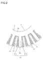
- Fig. 2 is an enlarged view showing a portion of the stator 2.
- Each of the teeth 4b has a letter-T shape having a tooth body portion 40 upon which a coil 6 is installed and projecting end portions 41a and 41b, with vacant spaces 8 being formed at the bases of the projecting end portions 41a and 41b. Slots 16 are defined between the teeth 4b for receiving the coils 6.
- the feature of the vacant spaces 8 being provided at the bases of the projecting end portions 41a and 41b is a specific characteristic of the rotating electrical machine of this embodiment.
- Fig. 3 is a figure showing a portion of one of the core plates 30 that are laminated together to constitute the core 3.
- the projecting end portions 41a and 41b of the teeth 4b extend in the circumferential direction so that they define letter-T shapes; but, at the stage of fabrication of the core plates 30, their projecting end portions 341a and 341b extend in the radial direction.
- Cutaways 318 are formed in letter-V shapes at the base portions of the projecting end portions 341a and 341b of the core plate 30.
- the angle ⁇ of these cutaways 318 is almost the same as the angle through which the projecting end portions 341a and 341b will be bent during the subsequent process of formation.
- the width dimension D2 of the portion at which the projecting end portions 341a and 341b are provided is set to be less than or equal to the width dimension D1 of the stem portion 340.
- the respective correspondences between the core plate 30 and the completed stator as a laminated body are that: the projecting end portions 341a and 341b correspond to the projecting end portions 41a and 41b; the annular portions 304a correspond to the cylinder portions 4a; the stem portions 340 correspond to the tooth body portions 40; and the cutaways 318 correspond to the letter-V shaped grooves 18 as will be described hereinafter.
- Figs. 4A through 11C are figures for explanation of the procedure for assembling this stator 2.
- Conducting wire 9 covered with an insulating layer is wound upon the bobbin 5 in advance, and in the process shown in Fig. 4A , in its state with the concentrated winding coil 6 wound upon it, the bobbin 5 is installed and fitted over the tooth 4b of the core 3 that has been made by laminating together the core plates 30.
- the tooth 4b is inserted into a through hole 5a formed in the bobbin 5.
- the letter-V shaped grooves 18 are defined on the side surfaces of the tooth 4b in the circumferential direction, being built up from the cutaways 318 of the core plates 30.
- Fig. 5 is a figure showing the process of installation of the bobbin 5: at its right side, it shows a state before installation of the bobbin 5 upon its tooth 4b; at its center it shows a state midway through the process of fitting the bobbin 5 over the tooth 4b; and at its left side it shows a state in which the installation of the bobbin 5 upon the tooth 4b has been completed.
- the width dimension D2 of the portion where the projecting end portions 341a and 341b are formed is set to be less than or equal to the width dimension D1 of the stem portion 340 (i.e. of the tooth body portion 40 in Fig. 5 ). Due to this, i.e. by setting D2 ⁇ D1, it becomes easy to perform the task of installing the bobbin 5.
- Figs. 4B and 5 When the bobbin 5 is installed upon the tooth body portion 40 of the tooth 4b, as shown in Figs. 4B and 5 , the projecting end portions 41a and 41b project outwards from the bobbin 5. Next, as shown in Fig. 6 , the projecting end portions 41a and 41b are formed by being bent around so that they extend in the circumferential direction.
- Fig. 7 is a figure showing the final shapes of the projecting end portions 41a and 41b after their formation has been completed.
- Figs. 8A through 10B are figures showing a procedure for bending the projecting end portions 41a and 41b. Since the angle through which the projecting end portions 41a and 41b are to be bent is approximately 90°, i.e. is quite large, accordingly, in the example shown in Figs. 8A through 10B , the projecting end portions 41a and 41b are not bent around in a single operation, but rather are separated and bent around in three stages by using formation punches 11 through 13 of three different types.
- the punches 11 and 12 shown in Figs. 8A through 9B are formed with convex working surfaces 11a and 12a, while the punch 13 shown in Figs. 10A and 10B is formed with a concave working surface 13a: this punch 13 is the punch that determines the final shapes of the projecting end portions 41a and 41b.
- the punch 11 that has a surface 11a formed at an angle of ⁇ 1 is positioned radially outward from the tooth 4b, and then the punch 11 is shifted in the direction shown by the arrow sign, so that the projecting end portions 41a and 41b are deformed until they reach the shapes shown in Fig. 8B . Due to this formation process, the projecting end portions 41a and 41b are plastically deformed around their base portions as centers, and, along with their angle of opening becoming ⁇ 1, the gaps of their letter-V shaped grooves 18 are narrowed down.
- the formation punch 11 having the angle ⁇ 1 is exchanged for the punch 12 that has the angle ⁇ 2 (that is greater than ⁇ 1), and, as shown in Fig. 9B , the projecting end portions 41a and 41b are further processed.
- the angle of opening between the projecting end portions 41a and 41b becomes ⁇ 2, and also the gaps of their letter-V shaped grooves 18 are further narrowed down.
- the projecting end portions 41a and 41b are formed into their final shapes, in other words into shapes that extend along the circumferential direction.
- Fig. 4C shows the state in which the projecting end portions 41a and 41b have been formed into their final shapes, and in which the radially outer surfaces of the projecting end portions 41a and 41b that have been bent around to extend in the circumferential direction are formed into almost circular arcs.
- the structure of a stator 2 that is made by forming the projecting end portions 41a and 41b after having installed the coils 6 upon the teeth 4b is such that, after the formation process, no vacant spaces are present at the base portions which correspond to the base portions of the present projecting end portions 41a and 41b.
- the gap sizes are carefully designed so that the magnetic flux saturation does not occur at the gaps.
- the connecting portions between the projecting end portions 41a and 41b and the tooth body portion 40 in other words the portions that become thin where the letter-V shaped grooves 18 are formed (i.e. the portions shown in Fig. 3 by the reference symbol A) come to be plastically deformed.
- the material at the side where the letter-V shaped grooves 18 are formed i.e. at the inside of the bending process
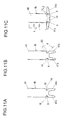
- Fig. 11C is a figure showing the shapes of the projecting end portions 41a and 41b after they have been bent around.
- the regions denoted by the reference symbol 10 are the curved portions at the base of the projecting end portions 41a and 41b, and vacant spaces 8 are defined at the insides of these curved portions 10 (towards the coil 6). Compressive stress operates at the insides of the curved portions 10, and tension stress acts at the outsides of the curved portions 10.
- the vacant spaces 8 are long and narrow groove shaped spaces that are defined by the projecting end portions 41a and 41b being bent around, so that the angles ⁇ of the letter-V shaped grooves 18 shown in Fig. 11B have become small. Due to this, the width dimension d of the grooves 8 after the bending around process becomes of the same order as the R dimension of the bottom portions of the letter-V shaped grooves 18.
- the core plates 30 are laminated together to form a core 3 of height 34 mm
- the width dimension d of the vacant spaces 8 becomes 0.1 mm to 0.2 mm.
- the length of the vacant spaces 8 is 0.8 mm. If the gaps of the vacant spaces 8 are of this order, then it is possible for the magnetic flux to flow across the vacant spaces 8, and it is possible for the influence upon the magnetic flux to be made extremely small.
- the R dimension that is appropriate for bulging to be prevented also depends upon the thickness dimension of the core plates 30, and, according to the results of actually performing this bending process and analysis of the resulting deformation and so on, it is desirable to set the R dimension to at least 30% to 60% of the core plate thickness.
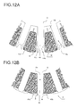
- a case is shown in Figs. 12A and 12B in which a distributed winding coil is used.
- a distributed winding coil may be formed by winding conducting wire covered with an insulating layer into a predetermined shape, and by covering it with an insulating layer 14.
- the distributed winding coil 15 that is thus formed is inserted into the slots 16 of the core 3.
- the stator 2 is formed by processing the projecting end portions 41a and 41b of the teeth 4b.
- Figs. 13A and 13B are figures showing a variant of the embodiment described above. In this variant embodiment as shown in Fig. 13A , it is arranged to form circular arcs 18a at the bottom portions of the letter-V grooves 18.
- Fig. 13B is a figure showing the shape after the bending process has been completed: the straight line portions of the letter-V grooves 18 are closely mutually closed together, and almost circular shaped vacant spaces 8 are defined.
- the dimensions of the letter-V shaped grooves 18 and of the circular arcs 18a may be set so that the shapes after the bending process is completed become as shown in Fig. 13B .
- the plurality of teeth 4b extend from the cylinder portion 4a of the stator core 3 in the radial direction, and the projecting end portions 41a and 41b are provided at its end so as to curve around.
- the projecting end portions 41a and 41b still have shapes that extend in the radial direction, and, after the stator coils 6 have been fitted into the slots 16, then the projecting end portions are bent around so as to extend in the circumferential direction, thus assuming a curved state in which they engage with the rotor side end surfaces of the stator coils 6.
- the structure is such that, in this curved state, vacant spaces 8 are created at the coil sides of the curved portions 10 to which the tooth body portion 40 and the projecting end portions 41a and 41b communicate, in other words at the base portions of the projecting end portions 41a and 41b.
- the flow of material during the bending process disperses along the edges of these vacant spaces 8, and it is possible to prevent bulging of the core plates out in the axial direction.
- the wedge shaped grooves 18 are defined between the projecting end portions 41a and 41b and the tooth body portion 40, and the bottom portions of these grooves 18 are formed in rounded shapes, with the circular arcs 18a being formed as shown in Figs. 13A and 13B so as to define smooth circular arcuate shapes.
- the present invention is not to be considered as being limited to an outer-rotor type electrical machine; it could also be applied to an inner-rotor type electrical machine having a structure in which the projecting end portions 41a and 41b are formed by being bent around in the circumferential direction after the coil has been installed to the stator core.
Landscapes
- Engineering & Computer Science (AREA)
- Power Engineering (AREA)
- Iron Core Of Rotating Electric Machines (AREA)
- Manufacture Of Motors, Generators (AREA)
Abstract
A rotating electrical machine includes: a rotor (1) to which a plurality of magnetic poles are provided along its circumferential direction; a stator core (3) laminating a plurality of core plates, and having a cylinder portion (4a) with teeth (4b) extending radially outwards; and a stator coil (6) received in a slot (16) between the teeth (4b); wherein each of the teeth (4b) includes: a tooth body portion (40) extending radially outwards from the cylinder portion (4a); and a pair of projecting end portions (41a,41b), provided at an end of the tooth body portion (40), that are in radially extended state before receiving the stator coil (6) in the slot (16), and that are in curved state in which they are bent in circumferential direction after receiving the stator coil (6) in the slot (16); and wherein, in the curved state, a vacant space (8) is defined at the slot side of a curved portion (10) that communicates the tooth body portion (40) and the projecting end portion (41a,41b).
Description
- The disclosure of the following priority application is herein incorporated by reference: Japanese Patent Application No.
2010-009062, filed January 19, 2010 - The present invention relates to a rotating electrical machine such as a motor or a generator or the like, and to a method for manufacturing a stator of a rotating electrical machine.
- As constructions for the coils to be employed for the stator of a rotating electrical machine, the concentrated winding format and the distributed winding format and so on are per se known. In the concentrated winding, a coil for one phase is wound upon a single core tooth, and therefore this has the advantage that it is possible to make the coils more compact, as compared with the case of a distributed winding. On the other hand, in the case of the distributed winding, a coil for one phase is subdivided into a plurality of coils and each subdivided coil is wound so as to straddle several core slots, and therefore this has the advantage that the electrical characteristics are better, as compared with the case of the concentrated winding. It should be understood that the coils are wound around the teeth with interposition of insulating material.
- Furthermore, from the point of view of the positional relationship between the stator and the rotor, rotating electrical machines can broadly be divided into the inner-rotor type in which the rotor rotates in the interior of the stator, and the outer-rotor type in which the rotor rotates over the exterior of the stator. In the case of the inner-rotor type, in general, the rotor is linked to a main shaft that transmits rotation, while, in the case of the outer-rotor type, in general, the rotor is linked to or is integrated with a rotating element that is to be directly driven, or indirectly drives a rotating element via a gear wheel or the like.
- For example, in the case of the outer-rotor type, a construction may be employed in which coils are installed into core slots from the exterior of the stator core. The stator core is fabricated by laminating a plurality of magnetic steel plates, and with such a stator core, it is desirable for the stator core to be of an integrated type from the viewpoint of reduction of iron loss; and moreover, from the viewpoint of reduction of copper loss in the coils, whichever of the concentrated winding and the distributed winding is employed as the coil winding method, it is desirable for the space factor of the coils in the slots to be high, by which the cross section of coil wires in each slot can be increased and therefore the coil resistance can be reduced.
- With the technique described in Japanese Laid-Open Patent Publication
H10-304609 2001-136701 - However, when the magnetic pole pieces that are shaped as projections in this way are being bent round to extend along the circumferential direction, it is easy for them to bulge outwards along the axial direction of the stator core, due to their base portions becoming creased. The stator core is made by laminating together magnetic steel plates, and, if creasing takes place in each of these magnetic steel plates and they bulge outwards in the axial direction, then the dimension of the stator core in its axial direction becomes larger, which is very undesirable, and this exerts a bad influence from the point of view of performance. The above problems are overcome by a rotating electrical machine and a method for manufacturing thereof according to the independent claims.
- According to the 1st aspect of the present invention, a rotating electrical machine comprises: a rotor to which a plurality of magnetic poles are provided along its circumferential direction; a stator core constructed by laminating together a plurality of core plates, and having a cylinder portion and a plurality of teeth that extend outwards in the radial direction from the cylinder portion; and a stator coil received in a slot between the teeth; wherein each of the teeth comprises: a tooth body portion that extends radially outwards from the cylinder portion; and a pair of projecting end portions, provided at an end of the tooth body portion, that are in extended state so as to extend in radial direction before the stator coil is received in the slot, and that are in curved state in which they are bent around in circumferential direction after the stator coil is received in the slot; and wherein, in the curved state, a vacant space is defined at the slot side of a curved portion that communicates the tooth body portion and the projecting end portion.
- According to the 2nd aspect of the present invention, in a rotating electrical machine according to the 1st aspect, it is preferred that the vacant space defined at the curved portions are communicated to the slot on its slot side.
- According to the 3rd aspect of the present invention, in a rotating electrical machine according to the 1st aspect, it is preferred that, at the slot side of the vacant spaces defined at the curved portions, the projecting end portions and the tooth body portion are closely contacted together.
- According to the 4th aspect of the present invention, in a rotating electrical machine according to any one of the
aspects 1 through 3, it is preferred that the stator coil is installed, in the extended state, by inserting a coil-formed conducting wire into the tooth body portion from outside; and in the extended state, the projecting end portions has a width dimension in the circumferential direction smaller than a width dimension of the tooth body portion in the circumferential direction. - According to the 5th aspect of the present invention, in a rotating electrical machine according to the 4th aspect, it is preferred that the plurality of teeth extend radially outwards from outer circumference of the cylinder portion; and the stator core is formed in a cylindrical shape, and is disposed via a gap within an inner circumference of the rotor.
- According to the 6th aspect of the present invention, a method of manufacturing a stator of a rotating electrical machine in which, after having installed a stator coil upon a tooth body portion that extends radially outward from a cylinder portion of a stator core, a pair of projecting end portions that are provided to extend in radial direction from the end of the tooth body portion are formed so as to be curved around in circumferential direction, and wherein: the pair of projecting end portions are curved so that, in their curved state, a vacant space is defined at the base portion of the projecting end portion.
- According to the present invention it is possible to prevent the projecting end portions bulging outwards in the axial direction of the core plates during the process of bending the projecting end portions.
-
- Fig. 1
- is a sectional view showing the general structure of a rotating electrical machine according to the present invention;
- Fig. 2
- is an enlarged view of a portion of a
stator 2; - Fig. 3
- is a figure showing a portion of one
core plate 30; - Figs. 4A, 4B and 4C
- are the figures showing the order in which the
stator 2 is assembled; - Fig. 5
- is a figure showing a process for installing a
bobbin 5; - Fig. 6
- is a figure showing a process for forming around projecting
end portions - Fig. 7
- is a figure showing shapes of the projecting
end portions - Figs. 8A and 8B
- are the figures showing a process for formation of the projecting
end portions punch 11; - Figs. 9A and 9B
- are the figures showing a further process for formation of the projecting
end portions punch 12; - Figs. l0A and 10B
- are the figures showing a yet further process for formation of the projecting
end portions punch 13; - Figs. 11A, 11B and 11C
- are the figures showing shapes for V-
grooves 18 andvacant spaces 8; - Figs. 12A and 12B
- are the figures showing a case in which a distributed
winding coils 15 are employed; and - Figs. 13A and 13B
- are the figures showing a variant embodiment.
- In the following, an embodiment for implementation of the present invention will be explained with reference to the drawings.
Fig. 1 is a sectional view showing the general structure of a rotating electrical machine according to the present invention. The rotating electrical machine shown inFig. 1 is a rotating electrical machine of the outer-rotor type having a concentrated winding coil, with arotor 1 being provided exterior to astator 2, around its outer circumference. Acore 3 of thestator 2 is made by laminating together elements (hereinafter termed "core plates") that are made by punching silicon steel sheet or the like. - A plurality of
teeth 4b are provided on the outer circumference of acylinder portion 4a of thecore 3, and are spaced at regular intervals around its circumferential direction, while being formed so as to extend radially. Abobbin 5 made from an insulating material is fitted upon each of theseteeth 4b, and a concentratedwinding coil 6 is wound upon thisbobbin 5. For example, conducting wire of a roughly rectangular cross section with an insulating cover layer may be used for this coil winding. As will be described hereinafter, with the rotating electrical machine of this embodiment, in order to make it easy to install thecoils 6 upon thecore 3, thebobbins 5 upon which the concentrated windingcoils 6 are wound are made so as to be installed upon theteeth 4b from the outside of thecore 3. - While in
Fig. 1 no terminal wires are shown as being connected to thecoils 6, actually an electric circuit is formed by connecting the neutral points of the coils which are respectively connected to terminal wires. And, while this is not shown in the figures, a plurality of permanent magnets, or a plurality of conducting rods of a squirrel-cage-shape made from for example copper, are installed coaxially in the interior of therotor 1, and both ends of this rotor are rotatably supported by bearings, thus constituting an electric motor or a generator. -
Fig. 2 is an enlarged view showing a portion of thestator 2. Each of theteeth 4b has a letter-T shape having atooth body portion 40 upon which acoil 6 is installed and projectingend portions vacant spaces 8 being formed at the bases of the projectingend portions Slots 16 are defined between theteeth 4b for receiving thecoils 6. The feature of thevacant spaces 8 being provided at the bases of the projectingend portions -
Fig. 3 is a figure showing a portion of one of thecore plates 30 that are laminated together to constitute thecore 3. With thestator 2 in its completed state shown inFigs. 1 and2 , the projectingend portions teeth 4b extend in the circumferential direction so that they define letter-T shapes; but, at the stage of fabrication of thecore plates 30, their projectingend portions -
Cutaways 318 are formed in letter-V shapes at the base portions of the projectingend portions core plate 30. The angle θ of thesecutaways 318 is almost the same as the angle through which the projectingend portions end portions stem portion 340. Moreover, while the R dimension of the portions at the bottoms of thecutaways 318 depends upon the thickness of thecore plate 30, if for example the plate thickness t=0.35 mm, this dimension may be at least R0.1 to R0.2. Even if the plate thickness is different, the ratio may be set to be almost similar. - The respective correspondences between the
core plate 30 and the completed stator as a laminated body are that: the projectingend portions end portions annular portions 304a correspond to thecylinder portions 4a; thestem portions 340 correspond to thetooth body portions 40; and thecutaways 318 correspond to the letter-V shapedgrooves 18 as will be described hereinafter. -
Figs. 4A through 11C are figures for explanation of the procedure for assembling thisstator 2. Conductingwire 9 covered with an insulating layer is wound upon thebobbin 5 in advance, and in the process shown inFig. 4A , in its state with the concentrated windingcoil 6 wound upon it, thebobbin 5 is installed and fitted over thetooth 4b of thecore 3 that has been made by laminating together thecore plates 30. Thus, thetooth 4b is inserted into a throughhole 5a formed in thebobbin 5. And the letter-V shapedgrooves 18 are defined on the side surfaces of thetooth 4b in the circumferential direction, being built up from thecutaways 318 of thecore plates 30. -
Fig. 5 is a figure showing the process of installation of the bobbin 5: at its right side, it shows a state before installation of thebobbin 5 upon itstooth 4b; at its center it shows a state midway through the process of fitting thebobbin 5 over thetooth 4b; and at its left side it shows a state in which the installation of thebobbin 5 upon thetooth 4b has been completed. As shown inFig. 3 , the width dimension D2 of the portion where the projectingend portions tooth body portion 40 inFig. 5 ). Due to this, i.e. by setting D2<D1, it becomes easy to perform the task of installing thebobbin 5. - When the
bobbin 5 is installed upon thetooth body portion 40 of thetooth 4b, as shown inFigs. 4B and5 , the projectingend portions bobbin 5. Next, as shown inFig. 6 , the projectingend portions Fig. 7 is a figure showing the final shapes of the projectingend portions -
Figs. 8A through 10B are figures showing a procedure for bending the projectingend portions end portions Figs. 8A through 10B , the projectingend portions punches Figs. 8A through 9B are formed withconvex working surfaces 11a and 12a, while thepunch 13 shown inFigs. 10A and 10B is formed with aconcave working surface 13a: thispunch 13 is the punch that determines the final shapes of the projectingend portions - In the first step shown in
Figs. 8A and 8B , thepunch 11 that has asurface 11a formed at an angle of θ1 is positioned radially outward from thetooth 4b, and then thepunch 11 is shifted in the direction shown by the arrow sign, so that the projectingend portions Fig. 8B . Due to this formation process, the projectingend portions grooves 18 are narrowed down. - Next, the
formation punch 11 having the angle θ1 is exchanged for thepunch 12 that has the angle θ2 (that is greater than θ1), and, as shown inFig. 9B , the projectingend portions end portions grooves 18 are further narrowed down. Finally, as shown inFigs. 10A and 10B , using thepunch 13 that has theconcave working surface 13a, the projectingend portions -
Fig. 4C shows the state in which the projectingend portions end portions end portions Fig. 7 , the shapes of the letter-V shapedgrooves 18 at the base portions of the projectingend portions vacant spaces 8. - In the prior art, as described in
Fig. 10 of Japanese Laid-Open Patent PublicationH10-304609 stator 2 that is made by forming the projectingend portions coils 6 upon theteeth 4b is such that, after the formation process, no vacant spaces are present at the base portions which correspond to the base portions of the present projectingend portions tooth body portions 40 of theteeth 4b to the projectingend portions end portions grooves 18 close up completely and tightly, so that no gaps are defined. - As explained later, in the present invention, the gap sizes are carefully designed so that the magnetic flux saturation does not occur at the gaps.
- Now, during the process of formation of the projecting
end portions Figs. 8A through 10B , the connecting portions between the projectingend portions tooth body portion 40, in other words the portions that become thin where the letter-V shapedgrooves 18 are formed (i.e. the portions shown inFig. 3 by the reference symbol A) come to be plastically deformed. At this time, the material at the side where the letter-V shapedgrooves 18 are formed (i.e. at the inside of the bending process) is compressed, while conversely, at the other side of thegroove 18, the material becomes pulled out. - On the other hand, as shown in Japanese Laid-Open Patent Publication
H10-304609 vacant spaces 8 like those shown inFig. 6 are formed, it is necessary for the bottom portions of the letter-V shapedgrooves 18 that are defined upon theteeth 4b to define angles that are as sharp at their bottoms as possible, as shown inFig. 11A . As a result, when the material on the inside of the bending process is compressed, due to this compression, the material flows and collects in the extremely narrow portion, so that the phenomenon of thecore plate 30 bulging outwards in its thickness direction may take place. When bulging takes place due to the process of formation of each of thecore plates 30 that are laminated together, the dimension in the axial direction of the end portions of the teeth becomes larger, so that, among various inconveniences, the performance is deteriorated, such as rotation balance deterioration. - However in this embodiment, by making the R dimensions of the
cutaways 318 shown inFig. 3 large, it is possible to reduce or prevent bulging such as occurred in the prior art. In the example shown inFig. 11A , since the R dimensions of the bottom portions of the letter-V shapedgrooves 18 are extremely small, accordingly the flow of material can easily collect in these narrow regions due to compression, as shown by the reference symbol B1. On the other hand, when the R dimensions are made larger as shown inFig. 11B , then it is possible to disperse the flow of material to these portions that are shaped in larger circular arcs (i.e. to the portions shown by the reference symbol B2), so that it is possible to reduce or prevent bulging of the material in the thickness direction of thecore plates 30. -
Fig. 11C is a figure showing the shapes of the projectingend portions reference symbol 10 are the curved portions at the base of the projectingend portions vacant spaces 8 are defined at the insides of these curved portions 10 (towards the coil 6). Compressive stress operates at the insides of thecurved portions 10, and tension stress acts at the outsides of thecurved portions 10. Thevacant spaces 8 are long and narrow groove shaped spaces that are defined by the projectingend portions grooves 18 shown inFig. 11B have become small. Due to this, the width dimension d of thegrooves 8 after the bending around process becomes of the same order as the R dimension of the bottom portions of the letter-V shapedgrooves 18. - To take a concrete example, in a case in which the thickness t is t=0.35 mm, the width D1 is D1=2 mm, and the
core plates 30 are laminated together to form acore 3 of height 34 mm, if the R dimension of the letter-V shapedgrooves 18 is made to be 0.2 mm, then the width dimension d of thevacant spaces 8 becomes 0.1 mm to 0.2 mm. The length of thevacant spaces 8 is 0.8 mm. If the gaps of thevacant spaces 8 are of this order, then it is possible for the magnetic flux to flow across thevacant spaces 8, and it is possible for the influence upon the magnetic flux to be made extremely small. It should be understood that the R dimension that is appropriate for bulging to be prevented also depends upon the thickness dimension of thecore plates 30, and, according to the results of actually performing this bending process and analysis of the resulting deformation and so on, it is desirable to set the R dimension to at least 30% to 60% of the core plate thickness. - While in the embodiment described above the
coil 6 was a concentrated winding coil, a case is shown inFigs. 12A and 12B in which a distributed winding coil is used. As shown inFigs. 12A and 12B , such a distributed winding coil may be formed by winding conducting wire covered with an insulating layer into a predetermined shape, and by covering it with an insulatinglayer 14. The distributed windingcoil 15 that is thus formed is inserted into theslots 16 of thecore 3. Next, thestator 2 is formed by processing the projectingend portions teeth 4b. Moreover, although in the example described above the distributed windingcoil 15 is inserted into theslots 16 after having been wound, the method of directly winding it upon thetooth body portions 40 of theteeth 4b would also be acceptable. Yet further, although in this embodiment a concentrated winding coil and a distributed winding coil have been described, coils wound in other ways could also be employed. -
Figs. 13A and 13B are figures showing a variant of the embodiment described above. In this variant embodiment as shown inFig. 13A , it is arranged to formcircular arcs 18a at the bottom portions of the letter-V grooves 18.Fig. 13B is a figure showing the shape after the bending process has been completed: the straight line portions of the letter-V grooves 18 are closely mutually closed together, and almost circular shapedvacant spaces 8 are defined. Conversely, the dimensions of the letter-V shapedgrooves 18 and of thecircular arcs 18a may be set so that the shapes after the bending process is completed become as shown inFig. 13B . In this case as well, it is possible to prevent bulging of thecore plates 30, since the flow of material is dispersed along thecircular arcs 18a during the bending process. Furthermore there is also the advantageous aspect that, since the straight line portions of the letter-V grooves 18 are closed together after the formation process, accordingly the flow of magnetic flux becomes better, as compared to the case described above. - As described above, in this embodiment, the plurality of
teeth 4b extend from thecylinder portion 4a of thestator core 3 in the radial direction, and the projectingend portions slots 16, the projectingend portions slots 16, then the projecting end portions are bent around so as to extend in the circumferential direction, thus assuming a curved state in which they engage with the rotor side end surfaces of the stator coils 6. The structure is such that, in this curved state,vacant spaces 8 are created at the coil sides of thecurved portions 10 to which thetooth body portion 40 and the projectingend portions end portions vacant spaces 8, and it is possible to prevent bulging of the core plates out in the axial direction. - Since it is arranged to form
vacant spaces 8 of this type, in the state before the bending process in which the projectingend portions tooth body portion 40, the wedge shapedgrooves 18 are defined between the projectingend portions tooth body portion 40, and the bottom portions of thesegrooves 18 are formed in rounded shapes, with thecircular arcs 18a being formed as shown inFigs. 13A and 13B so as to define smooth circular arcuate shapes. - It should be understood that although, in the embodiment described above, an example has been explained having a structure in which a coil that is wound in advance is fitted over the
tooth body portion 40 having thetooth 4b, it would also be possible to apply the present invention to the case of a structure such as one in which, with the projectingend portions tooth 4b, and subsequently the projectingend portions end portions - The embodiments described above may be employed singly or in combination. This is because it is possible to obtain the beneficial effect of each of the embodiments either singly or in synergy. Furthermore, the present invention is not to be considered as being limited by the embodiments described above in any way, provided that its specific characteristics are not lost.
- The above embodiments of the invention as well as the appended claims and figures show multiple characterizing features of the invention in specific combinations. The skilled person will easily be able to consider further combinations or sub-combinations of these features in order to adapt the invention as defined in the in the claims to his specific needs.
Claims (6)
- A rotating electrical machine, comprising:a rotor (1) to which a plurality of magnetic poles are provided along its circumferential direction;a stator core (3) constructed by laminating together a plurality of core plates, and having a cylinder portion (4a) and a plurality of teeth (4b) that extend outwards in the radial direction from the cylinder portion (4a); anda stator coil (6) received in a slot (16) between the teeth (4b);wherein each of the teeth (4b) comprises:a tooth body portion (40) that extends radially outwards from the cylinder portion (4a); anda pair of projecting end portions (41a, 41b), provided at an end of the tooth body portion (40), that are in extended state so as to extend in radial direction before the stator coil (6) is received in the slot (16), and that are in curved state in which they are bent around in circumferential direction after the stator coil (6) is received in the slot (16);and wherein, in the curved state, a vacant space (8) is defined at the slot (16) side of a curved portion (10) that communicates the tooth body portion (40) and the projecting end portion (41a, 41b).
- A rotating electrical machine according to Claim 1, wherein the vacant space (8) defined at the curved portions (10) are communicated to the slot (16) on its slot side.
- A rotating electrical machine according to Claim 1, wherein, at the slot side of the vacant spaces (8) defined at the curved portions (10), the projecting end portions (41a, 41b) and the tooth body portion (40) are closely contacted together.
- A rotating electrical machine according to any one of Claims 1 through 3, wherein:the stator coil (6) is installed, in the extended state, by inserting a coil-formed conducting wire into the tooth body portion (40) from outside; andin the extended state, the projecting end portions (41a, 41b) has a width dimension in the circumferential direction smaller than a width dimension of the tooth body portion (40) in the circumferential direction.
- A rotating electrical machine according to Claim 4, wherein:the plurality of teeth (4b) extend radially outwards from outer circumference of the cylinder portion (4a); andthe stator core (3) is formed in a cylindrical shape, and is disposed via a gap within an inner circumference of the rotor (1).
- A method of manufacturing a stator of a rotating electrical machine in which, after having installed a stator coil (6) upon a tooth body portion (40) that extends radially outward from a cylinder portion (4a) of a stator core (3), a pair of projecting end portions (41a, 41b) that are provided to extend in radial direction from the end of the tooth body portion (40) are formed so as to be curved around in circumferential direction, and wherein:the pair of projecting end portions (41a, 41b) are curved so that, in their curved state, a vacant space (8) is defined at a base portion of the projecting end portion.
Applications Claiming Priority (1)
| Application Number | Priority Date | Filing Date | Title |
|---|---|---|---|
| JP2010009062A JP5537964B2 (en) | 2010-01-19 | 2010-01-19 | Rotating electric machine |
Publications (1)
| Publication Number | Publication Date |
|---|---|
| EP2346143A2 true EP2346143A2 (en) | 2011-07-20 |
Family
ID=44010061
Family Applications (1)
| Application Number | Title | Priority Date | Filing Date |
|---|---|---|---|
| EP11151124A Withdrawn EP2346143A2 (en) | 2010-01-19 | 2011-01-17 | Rotating electrical machine and manufacturing method of a stator thereof |
Country Status (4)
| Country | Link |
|---|---|
| US (1) | US8354769B2 (en) |
| EP (1) | EP2346143A2 (en) |
| JP (1) | JP5537964B2 (en) |
| CN (1) | CN102130521B (en) |
Cited By (2)
| Publication number | Priority date | Publication date | Assignee | Title |
|---|---|---|---|---|
| EP3136568A1 (en) * | 2015-08-28 | 2017-03-01 | Johnson Electric S.A. | Single phase permanent magnet motor and method for making same |
| EP3203608A1 (en) * | 2016-02-03 | 2017-08-09 | Johnson Electric S.A. | Blower |
Families Citing this family (22)
| Publication number | Priority date | Publication date | Assignee | Title |
|---|---|---|---|---|
| WO2012137302A1 (en) * | 2011-04-05 | 2012-10-11 | トヨタ自動車株式会社 | Stator, method for manufacturing stator, and flat conductor for winding |
| JP5862145B2 (en) * | 2011-09-19 | 2016-02-16 | 日本電産株式会社 | Motor and motor manufacturing method |
| JP5641366B2 (en) * | 2012-01-25 | 2014-12-17 | 株式会社デンソー | Stator and stator manufacturing method |
| KR101437546B1 (en) * | 2012-09-13 | 2014-09-04 | 현대모비스 주식회사 | Stator assembly, axial flux permanent magnet motor and method for manufacturing stator |
| US20150001984A1 (en) * | 2013-06-28 | 2015-01-01 | Remy Technologies, Llc | In-slot stator winding compaction |
| EP2824811A1 (en) * | 2013-07-11 | 2015-01-14 | Siemens Aktiengesellschaft | Continuous stator winding wound on a coil carrier |
| CN107112820B (en) * | 2014-12-09 | 2019-07-30 | 三菱电机株式会社 | Manufacturing method of stator, manufacturing method of rotating electrical machine, and core block |
| CN105990916B (en) * | 2015-01-30 | 2020-03-17 | 德昌电机(深圳)有限公司 | Motor armature |
| CN105846564B (en) * | 2015-01-30 | 2020-04-21 | 德昌电机(深圳)有限公司 | Motor and stator structure thereof |
| DE102016101539A1 (en) * | 2015-01-30 | 2016-08-04 | Johnson Electric S.A. | electric motor |
| CN104753203B (en) * | 2015-04-22 | 2017-05-31 | 广东威灵电机制造有限公司 | Prefabricated stator punching, stator punching, Stator and electrical machine |
| CN104753205B (en) * | 2015-04-22 | 2017-05-31 | 广东威灵电机制造有限公司 | Prefabricated stator punching and the stator punching with it, Stator and electrical machine |
| CN104753198B (en) * | 2015-04-22 | 2017-10-27 | 广东威灵电机制造有限公司 | Prefabricated stator punching and stator punching, stator and motor with it |
| CN106130291A (en) * | 2015-05-08 | 2016-11-16 | 德昌电机(深圳)有限公司 | Blower fan and single-phase external rotor brushless electric machine thereof |
| DE202016102374U1 (en) * | 2015-05-08 | 2016-07-22 | Johnson Electric S.A. | Single-phase external rotor motor and rotor of it |
| DE202016102217U1 (en) * | 2015-05-08 | 2016-07-22 | Johnson Electric S.A. | Single-phase external rotor motor and stator of the same |
| US20160329762A1 (en) * | 2015-05-08 | 2016-11-10 | Johnson Electric S.A. | Single-phase Outer-Rotor Motor And Rotor Thereof |
| DE102016108276A1 (en) * | 2015-05-08 | 2016-11-10 | Johnson Electric S.A. | Single-phase external rotor motor and stator thereof |
| US10038348B2 (en) * | 2015-08-12 | 2018-07-31 | Regal Beloit America, Inc. | Liner, stator assembly and associated method |
| JP6652308B2 (en) * | 2016-06-13 | 2020-02-19 | 三菱電機株式会社 | Armature, rotating electric machine and method for manufacturing armature |
| DE102023212921A1 (en) * | 2023-12-19 | 2025-06-26 | Robert Bosch Gesellschaft mit beschränkter Haftung | Rotor of an electrical machine |
| JP2025121741A (en) * | 2024-02-07 | 2025-08-20 | 株式会社デンソー | Stator |
Citations (3)
| Publication number | Priority date | Publication date | Assignee | Title |
|---|---|---|---|---|
| JPH10304609A (en) | 1997-04-21 | 1998-11-13 | Mitsubishi Electric Corp | Outer rotor type motor and method of manufacturing the same |
| JP2001136701A (en) | 1999-08-23 | 2001-05-18 | Asmo Co Ltd | Method for manufacturing core and armature |
| JP2010009062A (en) | 2009-10-09 | 2010-01-14 | Oki Data Corp | Developing device and image forming apparatus |
Family Cites Families (16)
| Publication number | Priority date | Publication date | Assignee | Title |
|---|---|---|---|---|
| US713604A (en) * | 1900-01-02 | 1902-11-18 | Alexander Churchward | Dynamo-electric machine. |
| US919458A (en) * | 1906-03-09 | 1909-04-27 | Heinrich Poth | Field-pole for dynamo-electric machines. |
| JPH038048Y2 (en) * | 1984-11-02 | 1991-02-27 | ||
| JPH0732573B2 (en) * | 1987-06-03 | 1995-04-10 | 株式会社日立製作所 | Method of manufacturing rotating armature |
| US5250867A (en) * | 1991-11-20 | 1993-10-05 | General Electric Company | Permanent magnet brushless DC motor having reduced cogging |
| US6137201A (en) * | 1997-05-26 | 2000-10-24 | Denso Corporation | AC generator for vehicles |
| JPH11252832A (en) * | 1998-03-06 | 1999-09-17 | Asmo Co Ltd | Method for manufacturing core sheet, core and armature |
| JP2001074461A (en) | 1999-09-02 | 2001-03-23 | S S Kogyo:Kk | Ink-pad plumb bob equipped with light-receiving target |
| US6664696B1 (en) * | 2000-02-29 | 2003-12-16 | Seagate Technology Llc | Tooth saturation for reduced electromagnetic harmonics |
| JP3644344B2 (en) * | 2000-03-14 | 2005-04-27 | 株式会社デンソー | Armature |
| US6742238B2 (en) * | 2001-08-08 | 2004-06-01 | Delphi Technologies, Inc. | Flare tooth stator for an AC generator |
| JP2003224940A (en) * | 2002-01-29 | 2003-08-08 | Asmo Co Ltd | Rotating electric machine stator |
| FR2887697B1 (en) * | 2005-06-28 | 2010-11-19 | Valeo Equip Electr Moteur | ROTATING ELECTRIC MACHINE HAVING LOSS-REDUCING MEANS |
| CN100568675C (en) * | 2007-11-08 | 2009-12-09 | 常州市威普电子科技有限公司 | Manufacturing method of motor stator core and rotor core |
| JP4948474B2 (en) * | 2008-05-16 | 2012-06-06 | 株式会社富士通ゼネラル | Electric motor |
| US8847464B2 (en) * | 2008-06-12 | 2014-09-30 | General Electric Company | Electrical machine with improved stator flux pattern across a rotor that permits higher torque density |
-
2010
- 2010-01-19 JP JP2010009062A patent/JP5537964B2/en not_active Expired - Fee Related
-
2011
- 2011-01-13 CN CN201110021597.4A patent/CN102130521B/en not_active Expired - Fee Related
- 2011-01-17 EP EP11151124A patent/EP2346143A2/en not_active Withdrawn
- 2011-01-19 US US13/008,973 patent/US8354769B2/en not_active Expired - Fee Related
Patent Citations (3)
| Publication number | Priority date | Publication date | Assignee | Title |
|---|---|---|---|---|
| JPH10304609A (en) | 1997-04-21 | 1998-11-13 | Mitsubishi Electric Corp | Outer rotor type motor and method of manufacturing the same |
| JP2001136701A (en) | 1999-08-23 | 2001-05-18 | Asmo Co Ltd | Method for manufacturing core and armature |
| JP2010009062A (en) | 2009-10-09 | 2010-01-14 | Oki Data Corp | Developing device and image forming apparatus |
Cited By (3)
| Publication number | Priority date | Publication date | Assignee | Title |
|---|---|---|---|---|
| EP3136568A1 (en) * | 2015-08-28 | 2017-03-01 | Johnson Electric S.A. | Single phase permanent magnet motor and method for making same |
| EP3203608A1 (en) * | 2016-02-03 | 2017-08-09 | Johnson Electric S.A. | Blower |
| US10267319B2 (en) | 2016-02-03 | 2019-04-23 | Johnson Electric International AG | Blower |
Also Published As
| Publication number | Publication date |
|---|---|
| JP5537964B2 (en) | 2014-07-02 |
| US8354769B2 (en) | 2013-01-15 |
| CN102130521A (en) | 2011-07-20 |
| JP2011151884A (en) | 2011-08-04 |
| CN102130521B (en) | 2013-08-21 |
| US20110175485A1 (en) | 2011-07-21 |
Similar Documents
| Publication | Publication Date | Title |
|---|---|---|
| US8354769B2 (en) | Rotating electrical machine and manufacturing method of a stator thereof | |
| US8704422B2 (en) | Full round stator assembly and electromagnetic machine having high slot fill | |
| CN103023167B (en) | Motor and method of manufacturing motor | |
| JP5028234B2 (en) | Rotating electric machine and stator manufacturing method | |
| EP3211772B1 (en) | Stator production method and coil | |
| US9397541B2 (en) | Stator for electric rotating machine and method of manufacturing the same | |
| CN103296797B (en) | The stator of electric rotating machine | |
| US8704420B2 (en) | Stator for electric machine | |
| US11949284B2 (en) | Stator for a rotating electrical machine | |
| JP2010239721A (en) | Rotary electric machine | |
| JP5911018B2 (en) | Armature and rotating electric machine equipped with the armature | |
| JP2016152751A (en) | Stator for rotary electric machine | |
| DE102021202678A1 (en) | Method for producing a stator, and a stator and an electrical machine having such | |
| JP2004080944A (en) | Stator core for electric motor | |
| JP5988915B2 (en) | Rotating electric machine laminated iron core, rotating electric machine laminated iron core manufacturing method, stator and rotating electric machine | |
| JP5952701B2 (en) | Motor stator structure, brushless motor, and method for manufacturing motor stator structure | |
| US7239059B2 (en) | Stator of rotating electric machine and manufacturing method of the stator | |
| JP2011030320A (en) | Dynamo-electric machine and method of manufacturing the same | |
| JP4297929B2 (en) | Motor and motor manufacturing method | |
| JP5376262B2 (en) | Stator for rotating electric machine and method for manufacturing the same | |
| US20050258702A1 (en) | Multiple winding coil shapes for increased slot fill | |
| KR101154994B1 (en) | Stator core | |
| JP4818401B2 (en) | motor | |
| JP2011199991A (en) | Stator of rotary electric machine and method of manufacturing the same | |
| CN115118032A (en) | Stator base body for an electric machine, electric machine having a stator base body, and method for producing a stator base body |
Legal Events
| Date | Code | Title | Description |
|---|---|---|---|
| PUAI | Public reference made under article 153(3) epc to a published international application that has entered the european phase |
Free format text: ORIGINAL CODE: 0009012 |
|
| 17P | Request for examination filed |
Effective date: 20110510 |
|
| AK | Designated contracting states |
Kind code of ref document: A2 Designated state(s): AL AT BE BG CH CY CZ DE DK EE ES FI FR GB GR HR HU IE IS IT LI LT LU LV MC MK MT NL NO PL PT RO RS SE SI SK SM TR |
|
| AX | Request for extension of the european patent |
Extension state: BA ME |
|
| STAA | Information on the status of an ep patent application or granted ep patent |
Free format text: STATUS: THE APPLICATION HAS BEEN WITHDRAWN |
|
| 18W | Application withdrawn |
Effective date: 20161117 |