EP2346128A1 - Gas-insulated sensor module - Google Patents
Gas-insulated sensor module Download PDFInfo
- Publication number
- EP2346128A1 EP2346128A1 EP10194252A EP10194252A EP2346128A1 EP 2346128 A1 EP2346128 A1 EP 2346128A1 EP 10194252 A EP10194252 A EP 10194252A EP 10194252 A EP10194252 A EP 10194252A EP 2346128 A1 EP2346128 A1 EP 2346128A1
- Authority
- EP
- European Patent Office
- Prior art keywords
- housing
- measuring unit
- voltage measuring
- primary
- unit according
- Prior art date
- Legal status (The legal status is an assumption and is not a legal conclusion. Google has not performed a legal analysis and makes no representation as to the accuracy of the status listed.)
- Granted
Links
- 230000008878 coupling Effects 0.000 claims description 8
- 238000010168 coupling process Methods 0.000 claims description 8
- 238000005859 coupling reaction Methods 0.000 claims description 8
- 238000007373 indentation Methods 0.000 claims description 4
- 239000000615 nonconductor Substances 0.000 claims description 4
- 230000002787 reinforcement Effects 0.000 abstract 1
- 239000004020 conductor Substances 0.000 description 15
- 238000009413 insulation Methods 0.000 description 10
- 238000005259 measurement Methods 0.000 description 9
- XEEYBQQBJWHFJM-UHFFFAOYSA-N Iron Chemical group [Fe] XEEYBQQBJWHFJM-UHFFFAOYSA-N 0.000 description 7
- 238000004804 winding Methods 0.000 description 6
- 239000012212 insulator Substances 0.000 description 5
- 230000009467 reduction Effects 0.000 description 5
- 238000005266 casting Methods 0.000 description 3
- 238000013461 design Methods 0.000 description 3
- 238000009434 installation Methods 0.000 description 3
- CURLTUGMZLYLDI-UHFFFAOYSA-N Carbon dioxide Chemical compound O=C=O CURLTUGMZLYLDI-UHFFFAOYSA-N 0.000 description 2
- 229910018503 SF6 Inorganic materials 0.000 description 2
- 239000012080 ambient air Substances 0.000 description 2
- 230000008901 benefit Effects 0.000 description 2
- 238000010276 construction Methods 0.000 description 2
- 238000005538 encapsulation Methods 0.000 description 2
- 238000002955 isolation Methods 0.000 description 2
- 239000000463 material Substances 0.000 description 2
- 238000000034 method Methods 0.000 description 2
- 230000008569 process Effects 0.000 description 2
- 239000011347 resin Substances 0.000 description 2
- 229920005989 resin Polymers 0.000 description 2
- 239000007787 solid Substances 0.000 description 2
- SFZCNBIFKDRMGX-UHFFFAOYSA-N sulfur hexafluoride Chemical compound FS(F)(F)(F)(F)F SFZCNBIFKDRMGX-UHFFFAOYSA-N 0.000 description 2
- 229960000909 sulfur hexafluoride Drugs 0.000 description 2
- 229910002092 carbon dioxide Inorganic materials 0.000 description 1
- 239000001569 carbon dioxide Substances 0.000 description 1
- 230000000295 complement effect Effects 0.000 description 1
- 238000011038 discontinuous diafiltration by volume reduction Methods 0.000 description 1
- 230000000694 effects Effects 0.000 description 1
- 238000010292 electrical insulation Methods 0.000 description 1
- 238000011156 evaluation Methods 0.000 description 1
- 230000006872 improvement Effects 0.000 description 1
- 239000011810 insulating material Substances 0.000 description 1
- 239000012774 insulation material Substances 0.000 description 1
- 238000012432 intermediate storage Methods 0.000 description 1
- 238000004519 manufacturing process Methods 0.000 description 1
- 230000007246 mechanism Effects 0.000 description 1
- 238000012544 monitoring process Methods 0.000 description 1
- 238000005457 optimization Methods 0.000 description 1
- 229920001296 polysiloxane Polymers 0.000 description 1
- 230000001681 protective effect Effects 0.000 description 1
- 230000008439 repair process Effects 0.000 description 1
- 238000007789 sealing Methods 0.000 description 1
- 230000035939 shock Effects 0.000 description 1
- 238000003860 storage Methods 0.000 description 1
Images


Classifications
-
- H—ELECTRICITY
- H02—GENERATION; CONVERSION OR DISTRIBUTION OF ELECTRIC POWER
- H02B—BOARDS, SUBSTATIONS OR SWITCHING ARRANGEMENTS FOR THE SUPPLY OR DISTRIBUTION OF ELECTRIC POWER
- H02B13/00—Arrangement of switchgear in which switches are enclosed in, or structurally associated with, a casing, e.g. cubicle
- H02B13/02—Arrangement of switchgear in which switches are enclosed in, or structurally associated with, a casing, e.g. cubicle with metal casing
- H02B13/035—Gas-insulated switchgear
- H02B13/0356—Mounting of monitoring devices, e.g. current transformers
-
- H—ELECTRICITY
- H01—ELECTRIC ELEMENTS
- H01F—MAGNETS; INDUCTANCES; TRANSFORMERS; SELECTION OF MATERIALS FOR THEIR MAGNETIC PROPERTIES
- H01F38/00—Adaptations of transformers or inductances for specific applications or functions
- H01F38/20—Instruments transformers
- H01F38/22—Instruments transformers for single phase ac
- H01F38/24—Voltage transformers
-
- H—ELECTRICITY
- H01—ELECTRIC ELEMENTS
- H01H—ELECTRIC SWITCHES; RELAYS; SELECTORS; EMERGENCY PROTECTIVE DEVICES
- H01H33/00—High-tension or heavy-current switches with arc-extinguishing or arc-preventing means
Landscapes
- Engineering & Computer Science (AREA)
- Power Engineering (AREA)
- Transformers For Measuring Instruments (AREA)
- Measuring Instrument Details And Bridges, And Automatic Balancing Devices (AREA)
- Measuring Fluid Pressure (AREA)
- Connector Housings Or Holding Contact Members (AREA)
Abstract
Description
Die vorliegende Erfindung betrifft einen Baustein einer gasisolierten Hochspannungs-Schaltanlage, auch GIS genannt, insbesondere einen gasisolierten Hochspannungswandler. Solche gattungsgemässen Hochspannungsmodule dienen zur Erfassung von Spannungen an Primärleitern in einer GIS-Schaltanlage.The present invention relates to a component of a gas-insulated high-voltage switchgear, also called GIS, in particular a gas-insulated high-voltage converter. Such generic high voltage modules are used to detect voltages to primary conductors in a GIS switchgear.
Bei typischen GIS-Schaltanlagen werden die Spannungen der Phasenleiter, welche auf unterschiedlichen elektrischen Potentialen liegen, typischerweise in einem gasisolierten Hochspannungssensor, nachstehend auch Spannungswandler genannt, für alle Phasen gemeinsam oder in jeweils einem gasisolierten Hochspannungswandler pro Phase separat ermittelt. Einer gewissen Modularität der GIS-Schaltanlage folgend, weisen die Phasenleiter im Bereich der Hochspannungssensoren in Querrichtung zur Leiterachse verlaufende Leiterstummel auf, die in einem Anschlussbereich beim Anschlussflansch des entsprechenden gekapselten Gehäuses der GIS-Schaltanlage münden. Bei solchen GIS-Schaltanlagen weist die Spannungsmessungseinheit mit dem mindestens einen Spannungswandler typischerweise drei sich parallel zueinander erstreckende Primärphasenanschlüsse auf, welche jeweils mit einem Spannungstransformator zum Messen der jeweiligen Primärspannung verbunden sind. Die Primärphasenanschlüsse werden bei der Montage der Spannungsmessungseinheit an den Anschlussbereich der Leiterstummel angeschlossen. Anschliessend wird das metallgekapselte Gehäuse der Spannungsmessungseinheit mit Isoliergas, beispielsweise Schwefelhexafluorid gefüllt.In typical GIS switchgear, the voltages of the phase conductors, which are at different electrical potentials, typically in a gas-insulated high-voltage sensor, also referred to as voltage converter, determined separately for all phases together or in each case a gas-insulated high-voltage converter per phase. Following a certain modularity of the GIS switchgear, the phase conductors in the region of the high-voltage sensors have conductor stubs extending transversely to the conductor axis, which open into a connection region at the connection flange of the corresponding encapsulated housing of the GIS switchgear. In such GIS switchgear systems, the voltage measuring unit with the at least one voltage transformer typically has three primary phase connections extending parallel to one another, which are each connected to a voltage transformer for measuring the respective primary voltage. The primary phase connections are connected to the connection area of the conductor stubs during assembly of the voltage measurement unit. Subsequently, the metal-encapsulated housing of the voltage measuring unit is filled with insulating gas, for example sulfur hexafluoride.
Bei einem ersten Typ der Spannungsmessungseinheit sind sowohl die drei Primärphasenanschlüsse, wie auch die eigentliche entsprechende Messeinheit pro Phase gemeinsam in einem Gasraum gekapselt. Dabei sind die drei parallel zueinander ausgerichteten Primärphasenanschlüsse in einem gleichschenkligen Dreieck zueinander angeordnet, um eine optimale Anschlussgeometrie zu realisieren. Ein Vertreter des ersten Typs ist beispielsweise in der
Bei einem zweiten Typ der Spannungsmessungseinheit ist jeder Primärphasenanschluss, wie auch die eigentliche entsprechende Messeinheit für jede Phase in einem separaten Gasraum gekapselt. Bei einer solchen dreiphasigen Spannungsmessungseinheit sind daher typischerweise drei baugleiche Spannungswandler eingesetzt.In a second type of voltage measurement unit, each primary phase connection as well as the actual corresponding measurement unit for each phase is encapsulated in a separate gas space. In such a three-phase voltage measurement unit, therefore, typically three identical voltage transformers are used.
Aufgrund der zunehmenden Nachfrage nach kleineren, aber dennoch leistungsfähigen GIS für Mittel- und Hochspannungsanlagen, kommt der Kompaktheit einer GIS eine entscheidende Bedeutung zu.Due to the increasing demand for smaller, yet powerful GIS for medium and high voltage systems, the compactness of a GIS is of decisive importance.
Wenn von einer GIS beispielsweise höhere elektrische Leistungen bei gleichbleibendem Schutzgas und gleichbleibendem Funktionsaufbau und gleichbleibenden Materialien gefordert werden, wirkt sich das in der Regel negativ auf die Abmessungen der GIS aus, da die GIS aufgrund vergrösserter Gehäusedurchmesser beziehungsweise Abmessungen weniger Kompakt realisiert werden kann.For example, if a GIS requires higher electrical power with a constant shielding gas and a consistent functional design and consistent materials, this generally has a negative effect on the dimensions of the GIS, since the GIS can be made less compact due to increased housing diameters or dimensions.
Es ist eine Aufgabe der vorliegenden Erfindung, einen GIS-Sensormodul, etwa in Form eines gasisolierten Hochspannungswandlers vorzulegen, welcher eine kompaktere Bauweise eines Schaltfeldes ermöglicht.It is an object of the present invention to provide a GIS sensor module, such as in the form of a gas-insulated high-voltage converter, which allows a more compact design of a control panel.
Diese Aufgabe wird mit dem Gegenstand nach Anspruch 1 gelöst. In einer Basisausführungsform weist die gasisolierte Hochspannungsmessungseinheit mindestens zwei parallel zueinander verlaufend angeordnete Primärphasenanschlüsse auf, welche mit mindestens einer damit verbundenen Messeinheit zum Messen einer Primärspannung der Primärphasenanschlüsse verbunden ist. Die Primärphasenanschlüsse und die Messeinheiten sind gekapselt in einem Gehäuse der Hochspannungsmessungseinheit angeordnet. Das Gehäuse der erfindungsgemässen Hochspannungsmesseinheit weist pro Primärphasenanschluss jeweils eine separate gehäuseseitige Anschlussöffnung auf, welche den jeweiligen Primärphasenanschluss umgreift und, je nach Ausführungsform, beispielsweise in einen flanschartigen Adapterabschnitt des Gehäuses mündet. Die mindestens zwei Primärphasenanschlüsse sind derart in einer gemeinsamen Ebene angeordnet, dass das Gehäuse in einer senkrecht zu dieser Ebene verlaufenden Schnittebene einen langgezogenen Gehäusequerschnitt aufweist, dessen Länge (Gehäuselänge) grösser als dessen Breite (Gehäusebreite) ist. Die Primärphasenanschlüsse und die Messeinheiten sind in einem Gasraum des Gehäuses gemeinsam gekapselt angeordnet.This object is achieved with the subject matter of claim 1. In a basic embodiment, the gas-insulated high-voltage measuring unit has at least two parallel to each other extending arranged primary phase terminals, which is connected to at least one associated measuring unit for measuring a primary voltage of the primary phase terminals. The primary phase terminals and the measuring units are encapsulated in a housing of the high-voltage measuring unit. The housing of the high-voltage measuring unit according to the invention has, per primary phase connection, in each case a separate housing-side connection opening, which encompasses the respective primary phase connection and, depending on the embodiment, opens, for example, into a flange-like adapter section of the housing. The at least two primary phase terminals are arranged in a common plane in such a way that the housing has an elongated housing cross section in a sectional plane running perpendicular to this plane whose length (housing length) is greater than its width (housing width). The primary phase terminals and the measuring units are arranged together encapsulated in a gas space of the housing.
Im Fall einer Ausführungsform als dreiphasige Hochspannungsmesseinheit sind die Primärteile im Gasraum dadurch dreiphasig gekapselt und über die Steckverbindung jeweils einphasig aus der Hochspannungsmesseinheit herausgeführt. In jedem Fall dient je eine gehäuseseitige Anschlussöffnung zur separaten Aufnahme von einem einzigen Primärphasenanschluss. Unter dem Begriff 'einphasiger Isolator' wird ein elektrischer Isolator verstanden wird, durch welchen lediglich ein Nominalleiter (eine Primärphase) geführt ist.In the case of one embodiment as a three-phase high-voltage measuring unit, the primary parts in the gas space are thereby encapsulated in three-phase fashion and led out of the high-voltage measuring unit via the plug-in connection in each case in a single phase. In any case, each housing-side connection opening is used for separate recording of a single primary phase connection. The term 'single-phase insulator' is understood to mean an electrical insulator through which only a nominal conductor (a primary phase) is guided.
Der gemeinsame Gasraum der Hochspannungsmesseinheit ist gegen einen beispielsweise flanschartig ausgeführten Adapterabschnitt hin durch Gehäuserippen in der Art und Weise von drei einphasig gekapselten Primärphasenanschlüssen gestaltet, wobei die dadurch entstandenen Gasräume auf einer dem flanschartigen Adapterabschnitt abgewandten Ende der Hochspannungsmesseinheit hydraulisch in einen einzigen Gasraum münden. Der flanschartige Adapterabschnitt dient beispielweise als mechanische Kontaktfläche für die mechanische Befestigung mit einem Anschlussmodul.The common gas space of the high-voltage measuring unit is designed, for example, by a flange-like adapter section through housing ribs in the manner of three single-phase encapsulated primary phase terminals, wherein the resulting gas chambers on a flange adapter portion facing away from the end of the high-voltage measuring unit open hydraulically into a single gas space. The flange adapter section serves as a mechanical contact surface for mechanical fastening with a connection module, for example.
Diese Basisausführungsform weist im Vergleich zu einer Mehrphasigen oder mehreren einphasigen Hochspannungsmesseinheiten gleich mehrere Vorteile auf. Erstens erfordert die Hochspannungsmesseinheit aufgrund der mehrphasigen Kapselung der Primärphasenanschlüsse lediglich eine einzige Befüllung mit Isoliergas. Eine Teilbefüllung oder Füllung mit anderem Gas wie etwa Kohlendioxid für Transport der Hochspannungsmesseinheit an ihren Bestimmungsort, etwa einer Unterstation, ist dadurch nicht mehr notwendig. Ein zweiter Vorteil liegt darin, dass die Hochspannungsmesseinheit bereits komplett vormontierbar als Vormontageeinheit prüfbar ist, da die gasdichte Isolation der Hochspannungsmesseinheit vor der Inbetriebsetzungsphase vollständig realisierbar ist. Dies ist wünschenswert, denn oft werden Hochspannungsmesseinheiten/Spannungswandler örtlich an anderem Ort, beispielsweise durch Zulieferer oder Dritte fernab vom Herstellungsort eines klassischen GIS-Schaltfeldes gefertigt. Der Spannungswandler trifft typischerweise bei der Montage auf das Schaltfeld zum ersten Mal auf seinen konkreten Einsatzort.This basic embodiment has several advantages compared to a multiphase or multiple single-phase high-voltage measuring units. First, due to the multi-phase encapsulation of the primary phase terminals, the high voltage measurement unit requires only a single filling with insulating gas. A partial filling or filling with other gas such as carbon dioxide for transport of the high-voltage measuring unit to its destination, such as a substation, this is no longer necessary. A second advantage resides in the fact that the high-voltage measuring unit can already be completely pre-assembled as a pre-assembly unit, since the gas-tight insulation of the high-voltage measuring unit can be completely realized before the commissioning phase. This is desirable because often high-voltage measuring units / voltage converters are locally manufactured elsewhere, for example by suppliers or third parties, far away from the production location of a classic GIS control panel. For the first time, the voltage transformer typically encounters its specific place of installation when it is mounted on the control panel.
Zweitens erfordert die erfindungsgemässe Hochspannungsmesseinheit im Betrieb lediglich eine einzige Überwachung des Schutzgases/Isoliergases im gemeinsamen Gasraum der Hochspannungsmesseinheit. Drittens ist auch nur eine einzige Überdruckschutzmechanik, beispielsweise in Form einer Berstscheibe, erforderlich. Viertens ermöglicht die mehrphasige Kapselung der Primärphasenanschlüsse eine distanzmässig verhältnismässig nahe Anordnung zweier benachbarter Primärphasenanschlüsse unterschiedlichen elektrischen Potentials. Dies ermöglicht nicht zuletzt eine Verbesserung des Freiheitsgrades für die Konstruktion der Hochspannungsmesseinheit. Fünftens ermöglicht die gemeinsame Anordnung der Primärphasenanschlüsse in einem gemeinsamen Gasraum eine Optimierung der Masse des Gehäuses der Hochspannungsmesseinheit.Secondly, the high-voltage measuring unit according to the invention requires only a single monitoring of the protective gas / insulating gas in the common gas space of the high-voltage measuring unit during operation. Third, even a single overpressure protection mechanism, for example in the form of a rupture disk, is required. Fourth, the multi-phase encapsulation of the primary phase terminals allows a relatively relatively close arrangement of two adjacent primary phase terminals of different electrical potential. This not least allows an improvement in the degree of freedom for the construction of the high-voltage measuring unit. Fifth, the common arrangement of the primary phase connections in a common gas space allows optimization of the mass of the housing of the high-voltage measuring unit.
Wenn der Gasraum der Hochspannungsmesseinheit als Druckbehälter ausgelegt ist, welcher für einen Betrieb bei einem Nominaldruck von mindestens 2.5 bar (250000 Pa) im jeweiligen Gasraum ausgelegt sind, ist damit ein GIS-Hochspannungsmodul realisierbar. Im Betrieb ist die Hochspannungsmesseinheit in der Folge mit einem unter Druck stehenden Isoliergas wie etwa Schwefelhexafluorid oder dergleichen gefüllt, welches je nach beabsichtigten Spannungslevel beispielsweise unter 2, 6 oder mehr bar Druck steht.If the gas space of the high-voltage measuring unit is designed as a pressure vessel which is designed for operation at a nominal pressure of at least 2.5 bar (250,000 Pa) in the respective gas space, a GIS high-voltage module can thus be realized. In operation, the high-voltage measuring unit is subsequently filled with a pressurized insulating gas, such as sulfur hexafluoride or the like, which, depending on the intended voltage level, is for example below 2, 6 or more bar pressure.
In einer Ausführungsform, in welcher das Gehäuse zwei sich in Richtung der Länge erstreckende, einander gegenüberliegend angeordnete Gehäuseflanken aufweist, weist mindestens eine der Gehäuseflanken mindestens eine dem Absolutdruck entgegenwirkende Struktur auf. Darunter wird eine Struktur verstanden, welche der Gehäuseflanke beziehungsweise den Gehäuseflanken des Gehäuses genügend Festigkeit verleiht, um im Betrieb der Hochspannungsmesseinheit dem oben genannten Gasdruck zuverlässig zu widerstehen. Die Struktur dient also im Vergleich zu einer Gehäuseflanke ohne die erfindungsgemässe Struktur zur Erhöhung der Festigkeit und/oder Formstabilität der Gehäuseflanke durch die Struktur. Anders ausgedrückt weist eine der Gehäuseflanken mindestens eine dem Absolutdruck entgegenwirkende Struktur auf, um im Betrieb der Hochspannungsmessungseinheit einem Absolutdruck im Gasraum entgegenzuwirken. Unter Absolutdruck wird die Druckdifferenz zwischen dem Druck/Gasdruck innerhalb des Gasraums und ausserhalb des Gasraums verstanden. Je nach Gegebenheiten und Ausführungsform umfasst diese Struktur mindestens ein sich in Richtung der Primäranschlüsse erstreckendes Strukturelement, etwa in Form einer Rippe des Gehäuses. Wenn das Gehäuse durch Giessen hergestellt wird, lassen sich Rippen typischerweise wirtschaftlich herstellen. Ein durch Giessen hergestelltes Gehäuse ist in einer bevorzugten Ausführungsform der Hochspannungsmesseinheit ein- oder zweiteilig.In one embodiment, in which the housing has two casing flanks extending in the direction of the length, opposite one another, at least one of the casing flanks has at least one structure counteracting the absolute pressure. This is understood to mean a structure which gives the housing flank or the housing flanks of the housing sufficient strength to reliably withstand the abovementioned gas pressure during operation of the high-voltage measuring unit. The structure thus serves in comparison to a housing flank without the structure according to the invention for increasing the strength and / or dimensional stability of the housing flank by the structure. In other words, one of the housing flanks has at least one structure counteracting the absolute pressure in order to counteract an absolute pressure in the gas space during operation of the high-voltage measuring unit. Absolute pressure is understood to mean the pressure difference between the pressure / gas pressure inside the gas space and outside the gas space. Depending on the circumstances and embodiment, this structure comprises at least one structural element extending in the direction of the primary connections, for example in the form of a rib of the housing. When the housing is made by casting, ribs can typically be produced economically. A housing produced by casting is in one preferred embodiment of the high-voltage measuring unit in one or two parts.
Bei einer Ausführungsform einer Struktur, etwa einer Rippe, ist diese durch mindestens eine dem Absolutdruck im Gasraum entgegenwirkende Struktur durch eine lokale Einbuchtung des Gehäuses gebildet. Je nach Randbedingungen erfolgt die lokale Einbuchtung des Gehäuses durch einen Einzug der Breite und/oder der Länge des Gehäuses.In one embodiment of a structure, such as a rib, this is formed by at least one of the absolute pressure in the gas space counteracting structure by a local recess of the housing. Depending on the boundary conditions, the local indentation of the housing takes place by an indentation of the width and / or the length of the housing.
Alternativ oder ergänzend dazu ragt die mindestens eine Struktur ins Innere des Gehäuses hinein. Eine derartige Ausführungsform ist beispielsweise dann vorteilhaft, wenn vorstehende Teile vermieden werden sollen oder wenn die Struktur vor äusseren Beschädigungen geschützt sein soll.Alternatively or additionally, the at least one structure protrudes into the interior of the housing. Such an embodiment is for example advantageous if protruding parts should be avoided or if the structure should be protected from external damage.
Selbst bei im Gehäusequerschnitt gesehen langen und dünnen Wänden des Gehäuses sind gute Festigkeitswerte des Gehäuses erzielbar, wenn das Gehäuse in mindestens einem Abschnitt des primärseitigen Anschlussbereichs zwischen den Primärphasenanschlüssen verrippt ist. Dies gilt insbesondere dann, wenn die beiden Gehäuseflanken im Abschnitt des primärseitigen Anschlussbereichs über mindestens eine Rippe miteinander verbunden sind.Even with housing walls which are long and thin in the housing cross-section, good strength values of the housing can be achieved if the housing is ribbed in at least one section of the primary-side connection region between the primary phase connections. This applies in particular if the two housing flanks are connected to one another in the section of the primary-side connection region via at least one rib.
Ein besonders geringes Gasvolumen lässt sich mit Hochspannungsmessungseinheiten erreichen, bei denen die Primärphasenanschlüsse und/oder die Messeinheiten formmässig ineinander verzahnt angeordnet sind. Unter dem Begriff 'formmässig ineinander verzahnt' wird eine geometrische Orientierung bzw. Ausrichtung der Primärphasenanschlüsse und/oder die Messeinheiten relativ zueinander verstanden. Bei einer Ausführungsform der Messeinheiten als Spannungswandler mit je einem Eisenkern und einer Wicklungspackung weist die Messeinheit in Richtung des Primärphasenanschlusses gesehen einen kreuzförmigen Querschnitt im Bereich der Messeinheit auf. Eine Ineinanderverzahnung zweier benachbarter Messeinheiten ist durch eine Drehung der Messeinheiten um die jeweilige Längsachse der Primärphasenanschlüsse um einen Neigungswinkel und ein anschliessendes Gegeneinanderschieben in Richtung der Gehäuselänge erzielbar. Als Folge davon greifen konvexe Abschnitte der einen Messeinheit in konkave Abschnitte der benachbarten Messeinheit, wodurch der Abstand der zwei Messeinheiten und Primärphasenanschlüsse verringerbar ist. Letzteres erträgt positiv zur Volumenreduktion des Gasraums bei. Als Beispiel von formmässig ineinander verzahnt angeordneten Primärphasenanschlüsse seien an dieser Stelle zwei benachbarte Primärphasenanschlüsse mit je einem U-förmigen Querschnitt genannt, wobei ein Schenkel des ersten Primärphasenanschlusses zwischen den zwei Schenkeln des zweiten Primärphasenanschlusses angeordnet ist.A particularly low gas volume can be achieved with high-voltage measuring units in which the primary phase connections and / or the measuring units are arranged in a form-fitting manner in one another. The term 'form-fittingly interlocked' is understood to mean a geometric orientation or orientation of the primary phase connections and / or the measuring units relative to one another. In one embodiment of the measuring units as a voltage converter, each having an iron core and a winding package, the measuring unit has, seen in the direction of the primary phase connection, a cross-shaped cross section in the region of the measuring unit. An interlocking of two adjacent measuring units can be achieved by a rotation of the measuring units about the respective longitudinal axis of the primary phase connections by an angle of inclination and a subsequent pushing against each other in the direction of the housing length. As a result, engage convex portions of the a measuring unit in concave portions of the adjacent measuring unit, whereby the distance of the two measuring units and primary phase terminals is reduced. The latter contributes positively to the volume reduction of the gas space. As an example of form-fitting intermeshed arranged primary phase connections are at this point two adjacent primary phase terminals, each with a U-shaped cross-section, wherein a leg of the first primary phase terminal between the two legs of the second primary phase terminal is arranged.
Eine weitere Verringerung des Gasvolumens ist erzielbar, wenn der Gehäusequerschnitt in Richtung der Gehäuselänge und/oder in Richtung der Primärphasenanschlüsse zumindest abschnittweise einer gemeinsamen Umhüllenden der Messeinheiten und/oder der Primärphasenanschlüsse folgt.A further reduction of the gas volume can be achieved if the housing cross-section in the direction of the housing length and / or in the direction of the primary phase connections at least in sections follows a common envelope of the measuring units and / or the primary phase connections.
In einer besonders montagefreundlichen Ausführungsform der erfindungsgemässen Hochspannungsmessungseinheit ist zumindest einer der Primäranschlüsse im primärseitigen Anschlussbereich mit einer Trockensteckkontaktkupplung verbunden. Besonders vorteilhaft ist es, wenn alle Primärphasenanschlüsse über eine Steckkontaktkupplung, etwa in Form einer Trockensteckkontaktkupplung verbunden sind.In a particularly assembly-friendly embodiment of the high-voltage measuring unit according to the invention, at least one of the primary connections in the primary-side connection region is connected to a dry plug-in contact coupling. It when all primary phase terminals are connected via a plug-in contact coupling, such as in the form of a dry plug-in contact coupling is particularly advantageous.
Wenn die Steckverbindung als Trockensteckverbindung ausgebildet ist, ermöglicht dies ein Anschliessen der Hochspannungsmesseinheit an den benachbarten Modul (Anschlussmodul), ohne dass eine Isoliergasmanipulation wie etwa ein Evakuieren des Gasvolumens der Hochspannungsmesseinheit oder des benachbarten Moduls erforderlich ist. In der Folge ermöglich diese Ausführungsform einen wirtschaftlichen Reparatur- und (Wieder-) Inbetriebsetzungsprozess. Unter dem Begriff Trockensteckverbindung wird eine elektrisch isolierende Steckverbindung verstanden, welche eine Hochspannungsisolation an der Umgebungsluft ermöglicht. Dabei ist der Primäranschlusskontakt beziehungsweise Kontaktanschluss der Trockensteckverbindung elektrisch gegenüber typischerweise auf Erdpotential befindlichem Gehäuse durch einen Feststoffisolator isoliert. Je nach Ausführungsform der Trockensteckverbindung schmiegt sich an den Feststoffisolator und/oder den Kontaktanschluss ein Hochspannungsisolator aus einem duktilen, Isolationsmaterial wie etwa Silikon an. Mit anderen Worten ausgedrückt wird mittels im Adapterabschnitt beziehungsweise im Anschlussbereich der Steckverbindung eingefügter Dichtungen die erforderliche Gasdichtheit der Verbindung zwischen der Hochspannungsmesseinheit und dem Anschlussmodul gewährleistet. Beim Kuppelvorgang verdrängt das duktile Isolationsmaterial die Umgebungsluft weitestgehend aus der Steckkupplung.If the plug-in connection is designed as a dry plug-in connection, this makes it possible to connect the high-voltage measuring unit to the adjacent module (connection module) without requiring an insulating gas manipulation, such as evacuation of the gas volume of the high-voltage measuring unit or the adjacent module. As a result, this embodiment enables an economical repair and (re) commissioning process. The term dry plug connection is understood to mean an electrically insulating plug connection which enables high-voltage insulation in the ambient air. In this case, the primary terminal contact or contact terminal of the dry plug-in connection is electrically opposite to typically housing located at ground potential isolated a solid insulator. Depending on the embodiment of the dry plug-in connection, a high-voltage insulator made of a ductile, insulating material such as silicone fits snugly against the solid insulator and / or the contact connection. In other words, the required gas-tightness of the connection between the high-voltage measuring unit and the connection module is ensured by means of seals inserted in the adapter section or in the connection region of the plug-in connection. During the dome process, the ductile insulation material largely displaces the ambient air from the plug-in coupling.
Das Bauvolumen und/oder das Gasvolumen der Hochspannungsmessungseinheit lassen sich weiter reduzieren, wenn die Trockensteckkontaktkupplung einen zumindest teilweise integrierten elektrischen Isolator umfasst.The construction volume and / or the gas volume of the high-voltage measuring unit can be further reduced if the dry plug-in contact coupling comprises an at least partially integrated electrical insulator.
In der Zeichnung sind Ausführungsbeispiel der Erfindung rein schematisch dargestellt. Dabei zeigt:
- Fig. 1
- einen Längsschnitt durch eine erste Ausführungsform einer Hochspannungsmessungseinheit für drei Phasen, deren Primärphasenanschlüsse über eine Trockensteckkontaktkupplung mit einem benachbarten Modul elektrisch verbindbar sind;
- Fig. 2
- einen vereinfacht dargestellten Gehäusequerschnitt der ersten Ausführungsform entlang der Schnittebene II-II in
Figur 1 ; - Fig. 3
- einen vereinfacht dargestellten Gehäusequerschnitt einer zweiten Ausführungsform in der Darstellung analog zur
Figur 2 - Fig. 4
- einen vereinfacht dargestellten Gehäusequerschnitt einer dritten Ausführungsform in der Darstellung analog zur
Figur 2 - Fig. 5
- einen vereinfacht dargestellten Gehäusequerschnitt einer vierten, in der unteren Figur- hälfte dargestellten Ausführungsform in der Darstellung analog zur
Figur 2 - Fig. 6
- eine fünfte Ausführungsform einer Hochspannungsmessungseinheit für drei Phasen mit einer alternativen Ausführungsform der Trockensteckkontaktkupplung.
- Fig. 1
- a longitudinal section through a first embodiment of a high voltage measurement unit for three phases whose primary phase terminals are electrically connected via a dry plug-in contact with an adjacent module;
- Fig. 2
- a simplified housing cross-section of the first embodiment along the sectional plane II-II in
FIG. 1 ; - Fig. 3
- a simplified housing cross-section of a second embodiment in the representation analogous to
FIG. 2 ; - Fig. 4
- a simplified housing cross-section of a third embodiment in the representation analogous to
FIG. 2 ; - Fig. 5
- a simplified housing cross-section of a fourth, in the lower figure- half illustrated embodiment in the representation analogous to
FIG. 2 ; and - Fig. 6
- a fifth embodiment of a high voltage measurement unit for three phases with an alternative embodiment of the dry plug-in contact coupling.
Der Längsschnitt durch eine erste Ausführungsform zweier dreiphasig gekapselter HV-GIS-Module in entkuppeltem Zustand von
In einer Basisvariante ist ein isolierender Abschnitt des Buchsenelementes 13 aus Giessharz gefertigt, während eine leitende, metallische Steckerbuchse 15 als Nominalleiteranschluss des Buchsenelements 13 dient. Je nach Anforderungen sind anstelle des Giessharzes andere, geeignete Materialen jedoch dafür einsetzbar. Die elektrische Verbindung der Steckverbindungen 9 erfolgt über die Steckerbuchse 15 und den ebenfalls metallischen Kontaktanschluss.In a basic variant, an insulating portion of the
Das Gehäuse 3 begrenzt einen Gasraum 16, welcher pro Primärphasenanschluss jeweils in einer gehäuseseitigen Anschlussöffnung 17 mündet, die den jeweiligen Primärphasenanschluss 5, 6, 7 umgreift und in einem flanschartigen Adapterabschnitt 19 mündet.The
Je nach Ausführung des Anschlussmoduls, ist der flanschartige Adapterabschnitte 19 beispielsweise über eine stilisiert dargestellte Schraubverbindung 20 mechanisch miteinander verbindbar.Depending on the design of the connection module, the flange-like adapter sections 19 can be mechanically connected to one another, for example, via a screw connection 20 shown stylized.
Die flanschseitige Abdichtung des Gasraumes 16 erfolgt über Isolationsabschnitte der Buchsenelemente 13, welche im Betrieb gleichzeitig die elektrische Isolation des Primärphasenanschlusses gegen Masse - sprich dem Gehäuse 3 - gewährleisten. Ein mehrteilig ausgeführter Isolationskörper 25 umfasst entsprechend drei Isolationsabschnitte der Buchsenelemente 13. Diese drei Isolationsabschnitte sind jeweils als becherförmige Isolationselemente 26 realisiert.The flange-side sealing of the
Aus
Das Gehäuse 3 weist zur Befestigung mit dem Deckel in einem dem flanschartigen Adapterabschnitt abgewandten Ende ebenfalls einen Flanschanschluss auf, welcher beispielsweise mit Durchgangslöchern oder Innengewinden zur Etablierung der Verschraubung 4 mit dem Deckel 2 auf. Am Deckel 2 sind alle Sekundärseitigen Schnittstellen der Spannungsmessung, nachfolgend vereinfachend als Messabgriff 30 bezeichnet, angeordnet. Vom Messabgriff 30 sind Daten/Signale für eine Auswerteeinheit entnehmbar. Weiter umfasst der Deckel 2 sämtliche Einheiten, welche im Zusammenhang mit dem Isoliergas benötigt werden, beispielsweise einen Berstschutz 31 mit einer Berstscheibeneinrichtung sowie einen Dichtheitswächter 32, beispielsweise in Form eines Drucksensors und einen Befüll- und Entleerstutzen 33.The
In Zusammenschau mit
Der gemeinsame Gasraum 16 der Hochspannungsmesseinheit 1 ist gegen den flanschartigen Adapterabschnitt 19 hin durch erste Gehäuserippen 23 wie drei einphasig gekapselte Primärphasenanschlüsse gestaltet, wobei die dadurch entstandenen Teilräume 34 des Gasraums 16 auf einer dem flanschartigen Adapterabschnitt 19 abgewandten Ende der Hochspannungsmesseinheit 1 hydraulisch in einen einzigen Gasraum 16 münden. Die Gehäuserippen 23 sind in einem Gehäuseabschnitt 14 des primärseitigen Anschlussbereichs zwischen den Primärphasenanschlüssen angeordnet.The
In
Aus der Schnittansicht von
In der in
Das Gehäuse 3 weist pro sich in X-Richtung erstreckende Gehäuseflanke 39 je zwei dem Absolutdruck entgegenwirkende Strukturelemente in Form von Versteifungsrippen 41 auf, welche in X-Richtung in etwa mittig zwischen zwei benachbarten Messeinheiten 8 angeordnet sind. Ein sich in Richtung der Primäranschlüsse erstreckendes Strukturelement in Form von Versteifungsrippen 41 ragt derart ins Innere des Gehäuses 3, also den Gasraum 16 hinein, dass eine äussere Querschnittskontur des Gehäuses davon unbeeinflusst bleibt.The
In der
Anders als bei der ersten Ausführungsform der Hochspannungsmesseinheit ist die dem Absolutdruck entgegenwirkende Struktur in Form von Versteifungsrippen 41a der zweiten Ausführungsform der Hochspannungsmesseinheit 1a durch jeweils eine lokale Einbuchtung des Gehäuses 3 beziehungsweise der Gehäusewand gebildet. Durch einen vergrösserten Neigungswinkel 40 von Wicklungen 10 und Eisenkernen 24 resultiert eine sich in X-Richtung erstreckende Gehäuselänge 37a, welche bei denselben Randbedingungen wie bei der ersten Ausführungsform der Hochspannungsmesseinheit leicht kürzer ist, als dessen Gehäuselänge 37. Analoges gilt für eine sich in Y-Richtung erstreckende Gehäusebreite 42a, welche kürzer als die Gehäusebreite 42 der ersten Ausführungsform der Hochspannungsmesseinheit ist. Diese Massnahme ermöglicht eine Verringerung des Volumens des Gasraums 16 gegenüber der ersten Ausführungsform.Unlike the first embodiment of the high-voltage measuring unit, the structure counteracting the absolute pressure in the form of stiffening
In der
Im Unterschied zur zweiten Ausführungsform sind die Wicklungen 10 und Eisenkerne 24 nicht nur um den Neigungswinkel 40 gedreht, sondern in X-Richtung zudem formmässig ineinander verzahnt angeordnet. Diese Massnahme ermöglicht im Vergleich zur Gehäuselänge 37a derart zu verringern, dass eine Gehäuselänge 37b resultiert. Diese Massnahme ermöglicht eine weitere Verringerung des Volumens des Gasraums 16 gegenüber der ersten Ausführungsform.Unlike the second embodiment, the
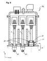
Die in der
Aus der unteren Hälfte des in
In der
Anders als bei der ersten Ausführungsform der Hochspannungsmesseinheit weist diese Ausführungsform der Hochspannungsmesseinheit 1d sowohl weibliche, als auch männliche Kontakteile der Steckverbindung 9 auf. Die dadurch erzielte Codierung erlaubt bei der Montage der Hochspannungsmesseinheit 1d am benachbarten Modul eine zweifelsfreie Einbaulage. Dadurch können potentielle Fehler von verwechselten Phasen 5, 7, beispielsweise verwechselte R und T-Phasen zum Vornherein sicher ausgeschlossen werden.Unlike the first embodiment of the high-voltage measuring unit, this embodiment of the high-voltage measuring unit 1 d has both female and male contact parts of the
Wie aus den in
Es versteht sich von selbst, dass die unterschiedlich geformten Elemente 13, 45 unterschiedliche Isolatoren zur elektrischen Isolation der Primärteile gegen Masse (Gehäuse) erfordern. Der mehrteilig ausgeführte Isolationskörper 25 umfasst beim Primärphasenanschluss 7 rechts ein becherförmiges Isolationselement 26, während die stiftförmigen Kontaktanschlüsse 45 des linken und mittleren Primärphasenanschlusses 5, 6 in einer Basisausführungsform beispielsweise lediglich eine Isolationshülse 46 aufweisen. Sowohl das becherförmige Isolationselement 26, als auch die Isolationshülse 46 bilden gasdichte, feste Verbindungen des elektrischen Isolators zum Gehäuse 3 im Bereich des flanschartigen Adapterabschnittes 19. Anders ausgedrückt, bilden die Isolationshülsen 46 und das becherförmige Isolationselement 26 gemeinsam den Isolationskörper 25 der Hochspannungsmesseinheit 1a.It goes without saying that the differently shaped
Als Alternative zu einer Ausführungsform der Hochspannungsmesseinheit als Hochspannungswandler zum Messen einer Hochspannung kann eine weitere Ausführungsform der Hochspannungsmesseinheit mindestens einen kapazitiven Spannungsteiler aufweisen.As an alternative to an embodiment of the high-voltage measuring unit as a high-voltage converter for measuring a high voltage, a further embodiment of the high-voltage measuring unit may have at least one capacitive voltage divider.
- 1, 1a, 1b, 1c, 1d1, 1a, 1b, 1c, 1d
- HochspannungsmesseinheitHigh voltage measuring unit
- 22
- Deckelcover
- 33
- Gehäuse der HochspannungsmesseinheitHousing of the high-voltage measuring unit
- 44
- Verschraubungscrew
- 5,6,75,6,7
- PrimärphasenanschlussPrimary phase connection
- 88th
- Messeinheit, MesswandlerMeasuring unit, instrument transformer
- 99
- Steckverbindungconnector
- 1010
- Wicklungwinding
- 1313
- Buchsenelement, buchsenförm. GegenkontaktBushing element, bush-shaped. countercontact
- 1414
- Abschnitt der HochspannungsmesseinheitSection of the high-voltage measuring unit
- 1515
- Steckerbuchsesocket
- 1616
- Gasraumheadspace
- 1717
- Gehäuseseitige AnschlussöffnungenHousing-side connection openings
- 1919
- Flanschartiger AdapterabschnittFlange-type adapter section
- 2020
- Schraubverbindungscrew
- 2222
- Erste EbeneFirst floor
- 2323
- Erste GehäuserippeFirst housing rib
- 2424
- Eisenkerniron core
- 2525
- Isolationskörper, IsolierkörperInsulating body, insulating body
- 2626
- Becherförmiges IsolationselementCup-shaped insulating element
- 3030
- Messabgriffmeasuring tap
- 3131
- BerstschutzBurst protection
- 3232
- DichtheitswächterLeak Guard
- 3333
- Befüll- und EntleerstutzenFilling and discharge nozzle
- 3434
- Teilraum des GasraumsPart space of the gas space
- 3535
- Zweite Ebenesecond level
- 3636
- Erste GeradeFirst straight
- 37,37a,37b,37c37,37a, 37b, 37c
- Gehäuselängehousing length
- 3838
- Abstanddistance
- 3939
- Gehäuseflankehousing edge
- 4040
- Neigungswinkeltilt angle
- 41,41a,41b,41c41,41a, 41b, 41c
- Versteifungsrippe, zweite GehäuserippeStiffening rib, second housing rib
- 42,42a,42b42,42A, 42b
- Gehäusebreitehousing width
- 4545
- Stiftförmiger KontaktanschlussPin-shaped contact connection
- 4646
- Isolationshülseinsulation sleeve
- 4747
- Umhüllendeenvelope
Claims (14)
Priority Applications (1)
| Application Number | Priority Date | Filing Date | Title |
|---|---|---|---|
| EP10194252A EP2346128B1 (en) | 2010-01-18 | 2010-12-09 | Gas-insulated sensor module |
Applications Claiming Priority (2)
| Application Number | Priority Date | Filing Date | Title |
|---|---|---|---|
| EP10150989 | 2010-01-18 | ||
| EP10194252A EP2346128B1 (en) | 2010-01-18 | 2010-12-09 | Gas-insulated sensor module |
Publications (2)
| Publication Number | Publication Date |
|---|---|
| EP2346128A1 true EP2346128A1 (en) | 2011-07-20 |
| EP2346128B1 EP2346128B1 (en) | 2012-11-21 |
Family
ID=42288534
Family Applications (1)
| Application Number | Title | Priority Date | Filing Date |
|---|---|---|---|
| EP10194252A Active EP2346128B1 (en) | 2010-01-18 | 2010-12-09 | Gas-insulated sensor module |
Country Status (3)
| Country | Link |
|---|---|
| EP (1) | EP2346128B1 (en) |
| KR (1) | KR101289837B1 (en) |
| CN (1) | CN102163817B (en) |
Cited By (3)
| Publication number | Priority date | Publication date | Assignee | Title |
|---|---|---|---|---|
| WO2015101634A1 (en) * | 2013-12-31 | 2015-07-09 | Siemens Aktiengesellschaft | Enclosure for voltage transformer and corresponding voltage transformer |
| EP3021436A1 (en) * | 2014-11-17 | 2016-05-18 | Siemens Aktiengesellschaft | Metal enclosure arrangement suitable for encapsulating a set of electrical components |
| US10276291B2 (en) * | 2017-01-12 | 2019-04-30 | Chyng Hong Electronic Co., Ltd. | Choke coil module of high power density DC-AC power inverter |
Families Citing this family (1)
| Publication number | Priority date | Publication date | Assignee | Title |
|---|---|---|---|---|
| DE102016210550B4 (en) * | 2016-06-14 | 2020-08-13 | Robert Bosch Gmbh | Sensor device and method for manufacturing a sensor device |
Citations (3)
| Publication number | Priority date | Publication date | Assignee | Title |
|---|---|---|---|---|
| EP0603619A1 (en) | 1992-12-19 | 1994-06-29 | ABBPATENT GmbH | Voltage converter |
| EP0755062A1 (en) * | 1995-07-12 | 1997-01-22 | Kommanditgesellschaft Ritz Messwandler GmbH & Co. | Encapsulated voltage transformer device for switching arrangements with several installation unit members |
| EP0780941A1 (en) * | 1995-12-22 | 1997-06-25 | ABB ADDA S.p.A. | Insulating post with a circuit breaker for high voltage and at least one measuring transformer |
Family Cites Families (3)
| Publication number | Priority date | Publication date | Assignee | Title |
|---|---|---|---|---|
| JPH0935957A (en) * | 1995-07-19 | 1997-02-07 | Hitachi Ltd | Electric apparatus |
| JP2000265720A (en) | 1999-03-16 | 2000-09-26 | Shiyoui Shinada | Vehicle thief confining device |
| JP2001085254A (en) | 1999-09-13 | 2001-03-30 | Toshiba Corp | Transformer for combined gas-insulated lightning arrester and grounding instrument |
-
2010
- 2010-12-09 EP EP10194252A patent/EP2346128B1/en active Active
-
2011
- 2011-01-14 KR KR1020110003882A patent/KR101289837B1/en active IP Right Grant
- 2011-01-18 CN CN201110027789.6A patent/CN102163817B/en active Active
Patent Citations (3)
| Publication number | Priority date | Publication date | Assignee | Title |
|---|---|---|---|---|
| EP0603619A1 (en) | 1992-12-19 | 1994-06-29 | ABBPATENT GmbH | Voltage converter |
| EP0755062A1 (en) * | 1995-07-12 | 1997-01-22 | Kommanditgesellschaft Ritz Messwandler GmbH & Co. | Encapsulated voltage transformer device for switching arrangements with several installation unit members |
| EP0780941A1 (en) * | 1995-12-22 | 1997-06-25 | ABB ADDA S.p.A. | Insulating post with a circuit breaker for high voltage and at least one measuring transformer |
Cited By (8)
| Publication number | Priority date | Publication date | Assignee | Title |
|---|---|---|---|---|
| WO2015101634A1 (en) * | 2013-12-31 | 2015-07-09 | Siemens Aktiengesellschaft | Enclosure for voltage transformer and corresponding voltage transformer |
| US20160300656A1 (en) * | 2013-12-31 | 2016-10-13 | Siemens Aktiengesellschaft | Enclosure for voltage transformer and corresponding voltage transformer |
| JP2017501593A (en) * | 2013-12-31 | 2017-01-12 | シーメンス アクティエンゲゼルシャフト | Enclosure for transformer and corresponding transformer |
| RU2667084C2 (en) * | 2013-12-31 | 2018-09-14 | Сименс Акциенгезелльшафт | Enclosure for voltage transformer and corresponding voltage transformer |
| US10304609B2 (en) * | 2013-12-31 | 2019-05-28 | Siemens Aktiengesellschaft | Enclosure for voltage transformer and corresponding voltage transformer |
| EP3021436A1 (en) * | 2014-11-17 | 2016-05-18 | Siemens Aktiengesellschaft | Metal enclosure arrangement suitable for encapsulating a set of electrical components |
| WO2016078907A1 (en) * | 2014-11-17 | 2016-05-26 | Siemens Aktiengesellschaft | Metal casing arrangement suitable for encapsulating an assembly of electrical components |
| US10276291B2 (en) * | 2017-01-12 | 2019-04-30 | Chyng Hong Electronic Co., Ltd. | Choke coil module of high power density DC-AC power inverter |
Also Published As
| Publication number | Publication date |
|---|---|
| CN102163817B (en) | 2014-04-02 |
| CN102163817A (en) | 2011-08-24 |
| KR20110084834A (en) | 2011-07-26 |
| EP2346128B1 (en) | 2012-11-21 |
| KR101289837B1 (en) | 2013-07-26 |
Similar Documents
| Publication | Publication Date | Title |
|---|---|---|
| EP2346128B1 (en) | Gas-insulated sensor module | |
| EP2873126B1 (en) | Gas-insulated switchgear | |
| WO2005074074A2 (en) | Compressed gas insulated separating switch component and leadthrough arrangement | |
| WO2010133500A1 (en) | Plug-in primary power connections of two modules of a high-voltage gas-insulated switchgear system | |
| EP2346053B1 (en) | Gas-isolated high voltage measuring unit | |
| WO2018046208A1 (en) | Transformer for high-voltage direct-current transmission | |
| EP1547218B1 (en) | Bus bar connection for a gas-insulated switchboard system | |
| DE10032656B4 (en) | Outdoor high voltage bushing and high voltage switchgear with such a bushing | |
| DE3904439C2 (en) | ||
| EP2254209B1 (en) | Pluggable primary output connections between two modules of a gas-insulated, high voltage switchgear | |
| EP2146411A2 (en) | Busbar coupling for an electrical switchgear | |
| EP0436256B1 (en) | Switchgear with a gas-filled container and multi-position rotary switch | |
| EP0796502B1 (en) | Metal-clad switchgear with a vacuum switching device | |
| DE2233217A1 (en) | DRUM LENGTH OF A GAS-INSULATED HIGH-VOLTAGE CABLE | |
| DE19850694B4 (en) | Gas-insulated switchgear | |
| DE19959450B4 (en) | Electrical connector, which automatically fills with insulating gas during assembly of insulating gas filled switchgear components | |
| EP0667662B1 (en) | Switchgear with connection channel | |
| DE10325682A1 (en) | Gas-insulated busbar component with outdoor bushing | |
| DE19850693B4 (en) | Pressure gas insulated switchgear | |
| EP3164919B1 (en) | Cable termination for connecting a switchgear assembly to a high-voltage cable | |
| DE19737430A1 (en) | Contact lead-through-type electrical coupling element for metal encapsulated gas-insulated functional areas of switching station | |
| DE102008024730A1 (en) | Arrangement with a gastight measuring bushing | |
| WO2011110298A2 (en) | Gas-insulated, metal-clad, single-phase or polyphase switchgear unit | |
| EP2905854B1 (en) | Capacitive voltage measuring device and a busbar device of a switchgear assembly and switchgear assembly | |
| DE975670C (en) | High current line |
Legal Events
| Date | Code | Title | Description |
|---|---|---|---|
| PUAI | Public reference made under article 153(3) epc to a published international application that has entered the european phase |
Free format text: ORIGINAL CODE: 0009012 |
|
| AK | Designated contracting states |
Kind code of ref document: A1 Designated state(s): AL AT BE BG CH CY CZ DE DK EE ES FI FR GB GR HR HU IE IS IT LI LT LU LV MC MK MT NL NO PL PT RO RS SE SI SK SM TR |
|
| AX | Request for extension of the european patent |
Extension state: BA ME |
|
| 17P | Request for examination filed |
Effective date: 20120119 |
|
| RIC1 | Information provided on ipc code assigned before grant |
Ipc: H02B 13/035 20060101AFI20120418BHEP |
|
| GRAP | Despatch of communication of intention to grant a patent |
Free format text: ORIGINAL CODE: EPIDOSNIGR1 |
|
| GRAS | Grant fee paid |
Free format text: ORIGINAL CODE: EPIDOSNIGR3 |
|
| GRAA | (expected) grant |
Free format text: ORIGINAL CODE: 0009210 |
|
| AK | Designated contracting states |
Kind code of ref document: B1 Designated state(s): AL AT BE BG CH CY CZ DE DK EE ES FI FR GB GR HR HU IE IS IT LI LT LU LV MC MK MT NL NO PL PT RO RS SE SI SK SM TR |
|
| REG | Reference to a national code |
Ref country code: GB Ref legal event code: FG4D Free format text: NOT ENGLISH |
|
| REG | Reference to a national code |
Ref country code: CH Ref legal event code: EP |
|
| REG | Reference to a national code |
Ref country code: CH Ref legal event code: NV Representative=s name: ABB SCHWEIZ AG INTELLECTUAL PROPERTY (CH-LC/IP, CH |
|
| REG | Reference to a national code |
Ref country code: AT Ref legal event code: REF Ref document number: 585498 Country of ref document: AT Kind code of ref document: T Effective date: 20121215 |
|
| REG | Reference to a national code |
Ref country code: IE Ref legal event code: FG4D Free format text: LANGUAGE OF EP DOCUMENT: GERMAN |
|
| REG | Reference to a national code |
Ref country code: DE Ref legal event code: R096 Ref document number: 502010001680 Country of ref document: DE Effective date: 20130117 |
|
| REG | Reference to a national code |
Ref country code: NL Ref legal event code: VDEP Effective date: 20121121 |
|
| REG | Reference to a national code |
Ref country code: LT Ref legal event code: MG4D |
|
| PG25 | Lapsed in a contracting state [announced via postgrant information from national office to epo] |
Ref country code: HR Free format text: LAPSE BECAUSE OF FAILURE TO SUBMIT A TRANSLATION OF THE DESCRIPTION OR TO PAY THE FEE WITHIN THE PRESCRIBED TIME-LIMIT Effective date: 20121121 Ref country code: LT Free format text: LAPSE BECAUSE OF FAILURE TO SUBMIT A TRANSLATION OF THE DESCRIPTION OR TO PAY THE FEE WITHIN THE PRESCRIBED TIME-LIMIT Effective date: 20121121 Ref country code: SE Free format text: LAPSE BECAUSE OF FAILURE TO SUBMIT A TRANSLATION OF THE DESCRIPTION OR TO PAY THE FEE WITHIN THE PRESCRIBED TIME-LIMIT Effective date: 20121121 Ref country code: FI Free format text: LAPSE BECAUSE OF FAILURE TO SUBMIT A TRANSLATION OF THE DESCRIPTION OR TO PAY THE FEE WITHIN THE PRESCRIBED TIME-LIMIT Effective date: 20121121 Ref country code: ES Free format text: LAPSE BECAUSE OF FAILURE TO SUBMIT A TRANSLATION OF THE DESCRIPTION OR TO PAY THE FEE WITHIN THE PRESCRIBED TIME-LIMIT Effective date: 20130304 Ref country code: NO Free format text: LAPSE BECAUSE OF FAILURE TO SUBMIT A TRANSLATION OF THE DESCRIPTION OR TO PAY THE FEE WITHIN THE PRESCRIBED TIME-LIMIT Effective date: 20130221 |
|
| PG25 | Lapsed in a contracting state [announced via postgrant information from national office to epo] |
Ref country code: PT Free format text: LAPSE BECAUSE OF FAILURE TO SUBMIT A TRANSLATION OF THE DESCRIPTION OR TO PAY THE FEE WITHIN THE PRESCRIBED TIME-LIMIT Effective date: 20130321 Ref country code: LV Free format text: LAPSE BECAUSE OF FAILURE TO SUBMIT A TRANSLATION OF THE DESCRIPTION OR TO PAY THE FEE WITHIN THE PRESCRIBED TIME-LIMIT Effective date: 20121121 Ref country code: SI Free format text: LAPSE BECAUSE OF FAILURE TO SUBMIT A TRANSLATION OF THE DESCRIPTION OR TO PAY THE FEE WITHIN THE PRESCRIBED TIME-LIMIT Effective date: 20121121 Ref country code: GR Free format text: LAPSE BECAUSE OF FAILURE TO SUBMIT A TRANSLATION OF THE DESCRIPTION OR TO PAY THE FEE WITHIN THE PRESCRIBED TIME-LIMIT Effective date: 20130222 Ref country code: PL Free format text: LAPSE BECAUSE OF FAILURE TO SUBMIT A TRANSLATION OF THE DESCRIPTION OR TO PAY THE FEE WITHIN THE PRESCRIBED TIME-LIMIT Effective date: 20121121 |
|
| BERE | Be: lapsed |
Owner name: ABB TECHNOLOGY A.G. Effective date: 20121231 |
|
| PG25 | Lapsed in a contracting state [announced via postgrant information from national office to epo] |
Ref country code: DK Free format text: LAPSE BECAUSE OF FAILURE TO SUBMIT A TRANSLATION OF THE DESCRIPTION OR TO PAY THE FEE WITHIN THE PRESCRIBED TIME-LIMIT Effective date: 20121121 Ref country code: EE Free format text: LAPSE BECAUSE OF FAILURE TO SUBMIT A TRANSLATION OF THE DESCRIPTION OR TO PAY THE FEE WITHIN THE PRESCRIBED TIME-LIMIT Effective date: 20121121 Ref country code: RS Free format text: LAPSE BECAUSE OF FAILURE TO SUBMIT A TRANSLATION OF THE DESCRIPTION OR TO PAY THE FEE WITHIN THE PRESCRIBED TIME-LIMIT Effective date: 20121121 Ref country code: MC Free format text: LAPSE BECAUSE OF NON-PAYMENT OF DUE FEES Effective date: 20121231 Ref country code: BG Free format text: LAPSE BECAUSE OF FAILURE TO SUBMIT A TRANSLATION OF THE DESCRIPTION OR TO PAY THE FEE WITHIN THE PRESCRIBED TIME-LIMIT Effective date: 20130221 Ref country code: SK Free format text: LAPSE BECAUSE OF FAILURE TO SUBMIT A TRANSLATION OF THE DESCRIPTION OR TO PAY THE FEE WITHIN THE PRESCRIBED TIME-LIMIT Effective date: 20121121 Ref country code: CZ Free format text: LAPSE BECAUSE OF FAILURE TO SUBMIT A TRANSLATION OF THE DESCRIPTION OR TO PAY THE FEE WITHIN THE PRESCRIBED TIME-LIMIT Effective date: 20121121 |
|
| PG25 | Lapsed in a contracting state [announced via postgrant information from national office to epo] |
Ref country code: NL Free format text: LAPSE BECAUSE OF FAILURE TO SUBMIT A TRANSLATION OF THE DESCRIPTION OR TO PAY THE FEE WITHIN THE PRESCRIBED TIME-LIMIT Effective date: 20121121 Ref country code: RO Free format text: LAPSE BECAUSE OF FAILURE TO SUBMIT A TRANSLATION OF THE DESCRIPTION OR TO PAY THE FEE WITHIN THE PRESCRIBED TIME-LIMIT Effective date: 20121121 Ref country code: IT Free format text: LAPSE BECAUSE OF FAILURE TO SUBMIT A TRANSLATION OF THE DESCRIPTION OR TO PAY THE FEE WITHIN THE PRESCRIBED TIME-LIMIT Effective date: 20121121 |
|
| REG | Reference to a national code |
Ref country code: IE Ref legal event code: MM4A |
|
| PLBE | No opposition filed within time limit |
Free format text: ORIGINAL CODE: 0009261 |
|
| STAA | Information on the status of an ep patent application or granted ep patent |
Free format text: STATUS: NO OPPOSITION FILED WITHIN TIME LIMIT |
|
| PG25 | Lapsed in a contracting state [announced via postgrant information from national office to epo] |
Ref country code: BE Free format text: LAPSE BECAUSE OF NON-PAYMENT OF DUE FEES Effective date: 20121231 |
|
| 26N | No opposition filed |
Effective date: 20130822 |
|
| PG25 | Lapsed in a contracting state [announced via postgrant information from national office to epo] |
Ref country code: IE Free format text: LAPSE BECAUSE OF NON-PAYMENT OF DUE FEES Effective date: 20121209 |
|
| PG25 | Lapsed in a contracting state [announced via postgrant information from national office to epo] |
Ref country code: MT Free format text: LAPSE BECAUSE OF FAILURE TO SUBMIT A TRANSLATION OF THE DESCRIPTION OR TO PAY THE FEE WITHIN THE PRESCRIBED TIME-LIMIT Effective date: 20121121 Ref country code: AL Free format text: LAPSE BECAUSE OF FAILURE TO SUBMIT A TRANSLATION OF THE DESCRIPTION OR TO PAY THE FEE WITHIN THE PRESCRIBED TIME-LIMIT Effective date: 20121121 |
|
| REG | Reference to a national code |
Ref country code: DE Ref legal event code: R097 Ref document number: 502010001680 Country of ref document: DE Effective date: 20130822 |
|
| PG25 | Lapsed in a contracting state [announced via postgrant information from national office to epo] |
Ref country code: TR Free format text: LAPSE BECAUSE OF FAILURE TO SUBMIT A TRANSLATION OF THE DESCRIPTION OR TO PAY THE FEE WITHIN THE PRESCRIBED TIME-LIMIT Effective date: 20121121 |
|
| PG25 | Lapsed in a contracting state [announced via postgrant information from national office to epo] |
Ref country code: LU Free format text: LAPSE BECAUSE OF NON-PAYMENT OF DUE FEES Effective date: 20121209 Ref country code: CY Free format text: LAPSE BECAUSE OF FAILURE TO SUBMIT A TRANSLATION OF THE DESCRIPTION OR TO PAY THE FEE WITHIN THE PRESCRIBED TIME-LIMIT Effective date: 20121121 Ref country code: SM Free format text: LAPSE BECAUSE OF FAILURE TO SUBMIT A TRANSLATION OF THE DESCRIPTION OR TO PAY THE FEE WITHIN THE PRESCRIBED TIME-LIMIT Effective date: 20121121 |
|
| PG25 | Lapsed in a contracting state [announced via postgrant information from national office to epo] |
Ref country code: HU Free format text: LAPSE BECAUSE OF FAILURE TO SUBMIT A TRANSLATION OF THE DESCRIPTION OR TO PAY THE FEE WITHIN THE PRESCRIBED TIME-LIMIT Effective date: 20101209 |
|
| REG | Reference to a national code |
Ref country code: DE Ref legal event code: R082 Ref document number: 502010001680 Country of ref document: DE |
|
| PG25 | Lapsed in a contracting state [announced via postgrant information from national office to epo] |
Ref country code: MK Free format text: LAPSE BECAUSE OF FAILURE TO SUBMIT A TRANSLATION OF THE DESCRIPTION OR TO PAY THE FEE WITHIN THE PRESCRIBED TIME-LIMIT Effective date: 20121121 |
|
| GBPC | Gb: european patent ceased through non-payment of renewal fee |
Effective date: 20141209 |
|
| PG25 | Lapsed in a contracting state [announced via postgrant information from national office to epo] |
Ref country code: GB Free format text: LAPSE BECAUSE OF NON-PAYMENT OF DUE FEES Effective date: 20141209 |
|
| REG | Reference to a national code |
Ref country code: FR Ref legal event code: PLFP Year of fee payment: 6 |
|
| PG25 | Lapsed in a contracting state [announced via postgrant information from national office to epo] |
Ref country code: IS Free format text: LAPSE BECAUSE OF FAILURE TO SUBMIT A TRANSLATION OF THE DESCRIPTION OR TO PAY THE FEE WITHIN THE PRESCRIBED TIME-LIMIT Effective date: 20121121 |
|
| REG | Reference to a national code |
Ref country code: DE Ref legal event code: R081 Ref document number: 502010001680 Country of ref document: DE Owner name: HITACHI ENERGY SWITZERLAND AG, CH Free format text: FORMER OWNER: ABB TECHNOLOGY AG, ZUERICH, CH Ref country code: DE Ref legal event code: R081 Ref document number: 502010001680 Country of ref document: DE Owner name: ABB POWER GRIDS SWITZERLAND AG, CH Free format text: FORMER OWNER: ABB TECHNOLOGY AG, ZUERICH, CH Ref country code: DE Ref legal event code: R081 Ref document number: 502010001680 Country of ref document: DE Owner name: ABB SCHWEIZ AG, CH Free format text: FORMER OWNER: ABB TECHNOLOGY AG, ZUERICH, CH |
|
| REG | Reference to a national code |
Ref country code: FR Ref legal event code: PLFP Year of fee payment: 7 |
|
| REG | Reference to a national code |
Ref country code: AT Ref legal event code: MM01 Ref document number: 585498 Country of ref document: AT Kind code of ref document: T Effective date: 20151209 |
|
| PG25 | Lapsed in a contracting state [announced via postgrant information from national office to epo] |
Ref country code: AT Free format text: LAPSE BECAUSE OF NON-PAYMENT OF DUE FEES Effective date: 20151209 |
|
| REG | Reference to a national code |
Ref country code: FR Ref legal event code: PLFP Year of fee payment: 8 |
|
| REG | Reference to a national code |
Ref country code: CH Ref legal event code: PFUS Owner name: ABB SCHWEIZ AG, CH Free format text: FORMER OWNER: ABB TECHNOLOGY AG, CH |
|
| REG | Reference to a national code |
Ref country code: FR Ref legal event code: TP Owner name: ABB SCHWEIZ AG, CH Effective date: 20180912 |
|
| REG | Reference to a national code |
Ref country code: CH Ref legal event code: PUE Owner name: ABB POWER GRIDS SWITZERLAND AG, CH Free format text: FORMER OWNER: ABB SCHWEIZ AG, CH |
|
| REG | Reference to a national code |
Ref country code: DE Ref legal event code: R081 Ref document number: 502010001680 Country of ref document: DE Owner name: HITACHI ENERGY SWITZERLAND AG, CH Free format text: FORMER OWNER: ABB SCHWEIZ AG, BADEN, CH Ref country code: DE Ref legal event code: R081 Ref document number: 502010001680 Country of ref document: DE Owner name: HITACHI ENERGY LTD, CH Free format text: FORMER OWNER: ABB SCHWEIZ AG, BADEN, CH Ref country code: DE Ref legal event code: R081 Ref document number: 502010001680 Country of ref document: DE Owner name: ABB POWER GRIDS SWITZERLAND AG, CH Free format text: FORMER OWNER: ABB SCHWEIZ AG, BADEN, CH Ref country code: DE Ref legal event code: R082 Ref document number: 502010001680 Country of ref document: DE Representative=s name: DENNEMEYER & ASSOCIATES S.A., DE |
|
| REG | Reference to a national code |
Ref country code: DE Ref legal event code: R081 Ref document number: 502010001680 Country of ref document: DE Owner name: HITACHI ENERGY SWITZERLAND AG, CH Free format text: FORMER OWNER: ABB POWER GRIDS SWITZERLAND AG, BADEN, CH Ref country code: DE Ref legal event code: R081 Ref document number: 502010001680 Country of ref document: DE Owner name: HITACHI ENERGY LTD, CH Free format text: FORMER OWNER: ABB POWER GRIDS SWITZERLAND AG, BADEN, CH |
|
| PGFP | Annual fee paid to national office [announced via postgrant information from national office to epo] |
Ref country code: CH Payment date: 20221213 Year of fee payment: 13 |
|
| P01 | Opt-out of the competence of the unified patent court (upc) registered |
Effective date: 20230527 |
|
| PGFP | Annual fee paid to national office [announced via postgrant information from national office to epo] |
Ref country code: FR Payment date: 20231221 Year of fee payment: 14 Ref country code: DE Payment date: 20231214 Year of fee payment: 14 |
|
| REG | Reference to a national code |
Ref country code: DE Ref legal event code: R082 Ref document number: 502010001680 Country of ref document: DE Representative=s name: DENNEMEYER & ASSOCIATES S.A., DE Ref country code: DE Ref legal event code: R081 Ref document number: 502010001680 Country of ref document: DE Owner name: HITACHI ENERGY LTD, CH Free format text: FORMER OWNER: HITACHI ENERGY SWITZERLAND AG, BADEN, CH |