EP2346060A1 - Medium voltage circuit breaker. - Google Patents
Medium voltage circuit breaker. Download PDFInfo
- Publication number
- EP2346060A1 EP2346060A1 EP10150948A EP10150948A EP2346060A1 EP 2346060 A1 EP2346060 A1 EP 2346060A1 EP 10150948 A EP10150948 A EP 10150948A EP 10150948 A EP10150948 A EP 10150948A EP 2346060 A1 EP2346060 A1 EP 2346060A1
- Authority
- EP
- European Patent Office
- Prior art keywords
- circuit breaker
- medium voltage
- voltage circuit
- control box
- coils
- Prior art date
- Legal status (The legal status is an assumption and is not a legal conclusion. Google has not performed a legal analysis and makes no representation as to the accuracy of the status listed.)
- Granted
Links
Images




Classifications
-
- H—ELECTRICITY
- H01—ELECTRIC ELEMENTS
- H01H—ELECTRIC SWITCHES; RELAYS; SELECTORS; EMERGENCY PROTECTIVE DEVICES
- H01H33/00—High-tension or heavy-current switches with arc-extinguishing or arc-preventing means
- H01H33/60—Switches wherein the means for extinguishing or preventing the arc do not include separate means for obtaining or increasing flow of arc-extinguishing fluid
- H01H33/66—Vacuum switches
- H01H33/666—Operating arrangements
-
- H—ELECTRICITY
- H01—ELECTRIC ELEMENTS
- H01R—ELECTRICALLY-CONDUCTIVE CONNECTIONS; STRUCTURAL ASSOCIATIONS OF A PLURALITY OF MUTUALLY-INSULATED ELECTRICAL CONNECTING ELEMENTS; COUPLING DEVICES; CURRENT COLLECTORS
- H01R13/00—Details of coupling devices of the kinds covered by groups H01R12/70 or H01R24/00 - H01R33/00
- H01R13/46—Bases; Cases
- H01R13/502—Bases; Cases composed of different pieces
- H01R13/504—Bases; Cases composed of different pieces different pieces being moulded, cemented, welded, e.g. ultrasonic welding, or swaged together
-
- H—ELECTRICITY
- H01—ELECTRIC ELEMENTS
- H01H—ELECTRIC SWITCHES; RELAYS; SELECTORS; EMERGENCY PROTECTIVE DEVICES
- H01H33/00—High-tension or heavy-current switches with arc-extinguishing or arc-preventing means
- H01H33/60—Switches wherein the means for extinguishing or preventing the arc do not include separate means for obtaining or increasing flow of arc-extinguishing fluid
- H01H33/66—Vacuum switches
- H01H33/662—Housings or protective screens
- H01H33/66207—Specific housing details, e.g. sealing, soldering or brazing
- H01H2033/6623—Details relating to the encasing or the outside layers of the vacuum switch housings
-
- H—ELECTRICITY
- H01—ELECTRIC ELEMENTS
- H01H—ELECTRIC SWITCHES; RELAYS; SELECTORS; EMERGENCY PROTECTIVE DEVICES
- H01H3/00—Mechanisms for operating contacts
- H01H3/22—Power arrangements internal to the switch for operating the driving mechanism
- H01H3/30—Power arrangements internal to the switch for operating the driving mechanism using spring motor
-
- H—ELECTRICITY
- H01—ELECTRIC ELEMENTS
- H01H—ELECTRIC SWITCHES; RELAYS; SELECTORS; EMERGENCY PROTECTIVE DEVICES
- H01H33/00—High-tension or heavy-current switches with arc-extinguishing or arc-preventing means
- H01H33/02—Details
- H01H33/022—Details particular to three-phase circuit breakers
Definitions
- the present invention relates to a medium voltage circuit breaker with improved features, and in particular to a medium voltage circuit breaker comprising an integrated control and diagnostic unit.
- medium voltage is referred to applications in the range of between 1 and 52 kV.
- Medium voltage circuit breaker are well known in the art. They usually consist of a pole assembly having, for each phase, a fixed contact and a movable contact. This latter is typically movable between a first position, in which it is coupled to the fixed contact, and a second position, in which it is uncoupled from said fixed contact, thereby realizing the opening and closing operation of the circuit breaker.
- the pole assembly is usually mounted on a base frame which is generally made of many separate components of metallic material, assembled by screws and/or welding.
- An actuator for actuating the opening and closing operation of the circuit breaker, and a kinematic chain, linking the actuators to the movable contacts, are usually also mounted onto the base frame.
- Medium voltage circuit breakers usually also comprises a number of auxiliary devices aimed at carrying out auxiliary functions for the circuit breaker.
- auxiliary functions normally includes a number of coils for the opening, closing, trip, shunt, undervoltage or blocking operation.
- auxiliary functions that need to be performed in a medium voltage circuit breaker are the spring charging operation of the actuator device for the mechanical operated circuit breaker. Also, auxiliary contacts are normally foreseen in order to detect the status of the main contacts of the circuit breaker. Still a further auxiliary equipment is the control system for the motor of the truck for circuit breakers in withdrawable configurations.
- a dedicated coil operating under a predefined voltage is normally required.
- auxiliary devices are separately assembled on the medium voltage circuit breaker, in the sense that each of them is separately mounted on the circuit breaker on the main assembly line thereof.
- they are prepared in three main subgroups (namely: auxiliary contacts, coils, and spring charging motor) and then assembled to the circuit breaker and separately wired to the main control system.
- the present invention is aimed at providing a medium voltage circuit breaker having a reduced number of mechanical parts.
- a further object of the present invention is to provide a medium voltage circuit breaker that does not need complicated wiring operation in the assembly phase.
- Still a further object of the present invention is to provide a medium voltage circuit breaker in which the various sub-components of the circuit breaker (e.g. pole assembly, actuator, auxiliary devices) can be pre-assembled and tested outside the main production line of the circuit breaker.
- the various sub-components of the circuit breaker e.g. pole assembly, actuator, auxiliary devices
- Still another object of the present invention is to provide a medium voltage circuit breaker in which the auxiliary devices of the circuit breaker can be pre-assembled and pre-tested outside the main production line of the circuit breaker.
- Another object of the present invention to provide a medium voltage circuit breaker in which the number of coils can be reduced.
- Still another object of the present invention is to provide a medium voltage circuit breaker with reduced manufacturing, installation and maintenance costs.
- the present invention relates to a medium voltage circuit breaker which is characterized in that it comprises an insulating base frame supporting:
- the use of an insulating base frame for supporting the pole assembly and said actuator allows to greatly simplify the production process of the circuit breaker.
- all components of the circuit breaker pole assembly, actuator, kinematic chain, possible auxiliary equipment
- the insulating base frame which is preferably made in one single piece.
- auxiliary components e.g., auxiliary contacts, coils, and spring charging motor
- the control box can be pre-assembled into the control box and pre-tested before assembling to the circuit breaker in the main assembly line.
- control box comprises an insulated casing for housing said plurality of accessory devices and a cover couplable to said insulated casing.
- said control box comprises co-moulded wirings for plug-in connection of said plurality of accessory devices.
- control box advantageously comprises at least a co-moulded connection of the plug-socket type for connection to said circuit breaker.
- the insulating base frame comprises at least a co-moulded connection of the plug-socket type for connecting to a corresponding plug-socket connection of said control box.
- said control box comprises a mechanical connection with said actuator.
- said control box comprises a local human machine interface for signaling the status and/or malfunctioning conditions of said circuit breaker.
- control box comprises an insulated casing for housing said plurality of accessory devices and a cover couplable to said insulated casing
- said local human machine interface is positioned on said cover of said control box.
- said auxiliary devices comprises one or more coils and/or one or more pairs of auxiliary contacts and/or a spring charging motor.
- said coils comprises one or more of the following coils: opening, closing, shunt, undervoltage or blocking coils.
- a preferred embodiment of the medium voltage circuit breaker according to the invention foresees that at least one of said coils is able to run with different voltages and perform different functions.
- said control box comprises a removable portion comprising an electronic board including diagnostic and control electronics.
- said control box comprises a removable portion comprising an electronic board including diagnostic and control electronics.
- a medium voltage circuit breaker designed with the reference number 1, in its more general definition, comprises an insulating base frame 2, which is conveniently made in one piece of insulating material.
- the insulating base frame 2 supports a pole assembly having, for each phase, an interruption unit housing a fixed contact and a movable contact reciprocally couplable/uncouplable between an open and a closed position (fixed and movable contacts are not shown in the attached drawings).
- circuit breaker 1 is a three-phase circuit breaker and thus comprises three interruption units 3, 4, and 5 which house corresponding sets of fixed/movable contacts reciprocally couplable/uncouplable between an open and closed position.
- Fixed and movable contacts can be conventional contacts of known type and therefore will not be described in more details.
- the circuit breaker according to the invention further comprises an actuator 6 to actuate the opening and closing operation of said circuit breaker.
- the actuator 6 normally comprises an actuating mechanism connected to the movable contact assembly through a kinematic chain (not shown).
- the actuator can be a conventional actuator of known type and therefore will not be described in more details, being known per se.
- circuit breaker 1 of the present invention comprises a control and diagnostic unit 7 which conveniently comprises a control box 8.
- the control box 8 substantially consists of a casing 81 which houses a plurality of accessory devices 50, 51, 52, 53, 54, 55 and 86 of said circuit breaker 1.
- the medium voltage circuit breaker 1 of the invention has the great advantage that all auxiliaries, or at least a good number of them, are grouped together inside the casing 81 of the control box 8.
- the whole assembly of the control box 8 can therefore be pre-assembled and pre-tested before being positioned in the insulating base frame 2, together with the interruption units 3, 4, and 5, the actuator 6 and the kinematic chain, with a consistent reduction of production times and costs.
- control box 8 the actuating mechanism of the actuator 6 and the kinematic chain can be conveniently covered by a casing 25 which is mechanically coupled (e.g. by clipping) to the insulating base frame 2.
- casing 25 has been partially cut-out in order to show the positioning of the control box 8 onto the insulating base frame 2
- control box 8 comprises an insulated casing 81 for housing said plurality of accessory devices 50, 51, 52, 53, 54, 55 and 86; the control box 8 then further comprises a cover 82 which is couplable to said insulated casing 81, in order to realize an enclosed environment.
- the control box 8 conveniently comprises co-moulded wirings for plug-in connection of said plurality of accessory devices 50, 51, 52, 53, 54, 55 and 86.
- the wirings and the connections thereof can be pre-arranged in the control box by, e.g. co-moulding the wirings and the connections. Then the auxiliary devices 50, 51, 52, 53, 54, 55 and 86 can be simply and quickly plugged-in into the corresponding connections in the control box 8.
- said control box 8 can conveniently comprise at least a co-moulded connection of the plug-socket type for connection to said circuit breaker 1.
- a connection e.g. a socket
- plug connection pre-arranged on the control box 8, said plug being couplable with a corresponding socket on the circuit breaker side.
- said insulating base frame 2 comprises a pre-arranged connection, e.g. at least a co-moulded connection of the plug-socket type for connecting to the above-mentioned corresponding plug-socket connection pre-arranged on said control box 8.
- control box 8 can conveniently comprise also a mechanical connection 50 with said actuator 6.
- said mechanical connection can be used for transmitting motion between one of the auxiliary devices (e.g. a spring charging motor) and the actuator 6 or to detect parameters of the main operating shaft of the actuator, e.g. position and/or speed and/or acceleration of the main operating shaft.
- said control box 8 advantageously comprises a local human machine interface 63 for signaling the status and/or malfunctioning conditions of said circuit breaker 1.
- the local human machine interface 63 can consist of a number of LEDs properly positioned on the exterior of the control box 8 so as to be visible by a user.
- said local human machine interface 63 is preferably positioned on said cover 82 of said control box 8.
- auxiliary devices 50, 51, 52, 53, 54, 55 and 86 a great variety thereof can be housed inside the control box 8.
- said auxiliary devices 50, 51, 52, 53, 54, 55 and 86 can comprise one or more coils 51, 52, 53 and 54 and/or one or more pairs of auxiliary contacts 86 and/or a spring charging motor 55.
- said coils 51, 52, 53 and 54 can comprise one or more of the following coils: opening, closing, shunt, undervoltage or blocking coils.
- At least one of said coils 51, 52, 53 and 54 is able to run with different voltages and perform different functions.
- said coils 51, 52, 53 and 54 is able to run with different voltages and perform different functions.
- control box 8 preferably comprises also an electronic device that handles the various components and allows a self-diagnostic to be carried out.
- said control box 8 preferably comprises a removable portion 82 positioned on said casing 81, said removable portion 82 comprising an electronic board including diagnostic and control electronics.
- diagnostic and control electronics allows to perform a number of functions, such as: control of the trip coils, control of the spring charging motor, control of the truck motor, detection of malfunctioning with local or remote alarms, monitoring the base parameters of the drive to determine the aging of the components thereof, interface with voltage and current sensors, etc.
- medium voltage circuit breaker of the invention have a number of advantages with respect to medium voltage circuit breaker of known type.
- the auxiliary devices are grouped together inside the casing 81 of the control box 8.
- the whole assembly of the control box 8 can therefore be pre-assembled and pre-tested before being positioned in the insulating base frame 2.
- the use of the insulating base frame 2 and of the control box 8 has a number of advantages with respect to conventional circuit breaker with an assembled base frame made of many metallic parts.
- the manufacturing process is greatly simplified since, in practice, the various components of the circuit breaker (interruption units, actuator, control box) are fixed to the insulating base frame 2, e.g. using screw means, said insulating base frame 2 being advantageously made in one piece.
- fixing means for instance screw means, can be used to fix the poles interruption units 3, 4, and 5, the actuator 6 and the control box 8 to the insulating base frame 2.
- the screw means can be inserted in the corresponding seats of the insulating base frame 2, from the bottom wall thereof. Therefore, the assembly process is extremely simple and can be highly automatize, thereby contributing to the reduction of the manufacturing times and costs.
- the production process for manufacturing the circuit breaker 1 is greatly simplified with respect to the conventional circuit breaker.
- the various sub-components of the circuit breaker e.g. pole assembly, actuator, kinematic chain
- the sub-components are then fixed to the insulating base frame in a very quick and highly automatized way.
- the medium voltage circuit breaker thus conceived may undergo numerous modifications and come in several variants, all coming within the scope of the inventive concept. Moreover, all the component parts described herein may be substituted by other, technically equivalent elements. In practice, the component materials and dimensions of the device may be of any nature, according to need and the state of the art.
Landscapes
- Breakers (AREA)
- Driving Mechanisms And Operating Circuits Of Arc-Extinguishing High-Tension Switches (AREA)
Abstract
a pole assembly having, for each phase, an interruption unit housing a fixed contact and a movable contact reciprocally couplable/uncouplable between an open and a closed position;
an actuator to actuate the opening and closing operation of said circuit breaker; and,
a control and diagnostic unit comprising a control box having a casing housing a plurality of accessory devices of said circuit breaker.
Description
- The present invention relates to a medium voltage circuit breaker with improved features, and in particular to a medium voltage circuit breaker comprising an integrated control and diagnostic unit. For the purposes of the present application the term medium voltage is referred to applications in the range of between 1 and 52 kV.
- Medium voltage circuit breaker are well known in the art. They usually consist of a pole assembly having, for each phase, a fixed contact and a movable contact. This latter is typically movable between a first position, in which it is coupled to the fixed contact, and a second position, in which it is uncoupled from said fixed contact, thereby realizing the opening and closing operation of the circuit breaker.
- The pole assembly is usually mounted on a base frame which is generally made of many separate components of metallic material, assembled by screws and/or welding. An actuator, for actuating the opening and closing operation of the circuit breaker, and a kinematic chain, linking the actuators to the movable contacts, are usually also mounted onto the base frame.
- Medium voltage circuit breakers usually also comprises a number of auxiliary devices aimed at carrying out auxiliary functions for the circuit breaker. Such auxiliary functions normally includes a number of coils for the opening, closing, trip, shunt, undervoltage or blocking operation.
- Other auxiliary functions that need to be performed in a medium voltage circuit breaker are the spring charging operation of the actuator device for the mechanical operated circuit breaker. Also, auxiliary contacts are normally foreseen in order to detect the status of the main contacts of the circuit breaker. Still a further auxiliary equipment is the control system for the motor of the truck for circuit breakers in withdrawable configurations.
- In addition, for each operation (e.g. shunt, tripping, undervoltage, block released, etc.) a dedicated coil, operating under a predefined voltage is normally required.
- The usual assembly processes of the circuit breaker, normally foresee a number of steps in which some of the components of the frame are assembled before mounting the actuator, poles and kinematic chain, while some others components of the frame are assembled after the actuator, poles and kinematic chain have been mounted.
- Typically the auxiliary devices are separately assembled on the medium voltage circuit breaker, in the sense that each of them is separately mounted on the circuit breaker on the main assembly line thereof. Alternatively, they are prepared in three main subgroups (namely: auxiliary contacts, coils, and spring charging motor) and then assembled to the circuit breaker and separately wired to the main control system.
- The known production processes of medium voltage circuit breakers are therefore long and complicated, both in terms of number of components and require manpower for the assembly operations.
- It is therefore an object of the present invention to provide a medium voltage circuit breaker in which the above-mentioned drawbacks are avoided or at least reduced.
- More in particular, it is an object of the present invention to provide a medium voltage circuit breaker whose production process is greatly simplified with respect to the conventional circuit breaker.
- As a further object, the present invention is aimed at providing a medium voltage circuit breaker having a reduced number of mechanical parts.
- A further object of the present invention is to provide a medium voltage circuit breaker that does not need complicated wiring operation in the assembly phase.
- Still a further object of the present invention is to provide a medium voltage circuit breaker in which the various sub-components of the circuit breaker (e.g. pole assembly, actuator, auxiliary devices) can be pre-assembled and tested outside the main production line of the circuit breaker.
- Still another object of the present invention is to provide a medium voltage circuit breaker in which the auxiliary devices of the circuit breaker can be pre-assembled and pre-tested outside the main production line of the circuit breaker.
- Another object of the present invention to provide a medium voltage circuit breaker in which the number of coils can be reduced.
- Still another object of the present invention is to provide a medium voltage circuit breaker with reduced manufacturing, installation and maintenance costs.
- Thus, the present invention relates to a medium voltage circuit breaker which is characterized in that it comprises an insulating base frame supporting:
- a pole assembly having, for each phase, an interruption unit housing a fixed contact and a movable contact reciprocally couplable/uncouplable between an open and a closed position;
- an actuator to actuate the opening and closing operation of said circuit breaker; and,
- a control and diagnostic unit comprising a control box having a casing housing a plurality of accessory devices of said circuit breaker.
- In this way, it is possible to overcome some of the disadvantages and drawbacks of the circuit breaker of the known art.
- In particular, the use of an insulating base frame for supporting the pole assembly and said actuator allows to greatly simplify the production process of the circuit breaker. In practice, all components of the circuit breaker (pole assembly, actuator, kinematic chain, possible auxiliary equipment) can be pre-assembled separately and then fixed in one step to the insulating base frame, which is preferably made in one single piece.
- Even more important, the auxiliary components (e.g., auxiliary contacts, coils, and spring charging motor) can be pre-assembled into the control box and pre-tested before assembling to the circuit breaker in the main assembly line.
- Preferably, in the Medium Voltage circuit breaker according to the invention the control box comprises an insulated casing for housing said plurality of accessory devices and a cover couplable to said insulated casing.
- According to a preferred embodiment, said control box comprises co-moulded wirings for plug-in connection of said plurality of accessory devices.
- In addition, the control box advantageously comprises at least a co-moulded connection of the plug-socket type for connection to said circuit breaker.
- In such a case, the insulating base frame comprises at least a co-moulded connection of the plug-socket type for connecting to a corresponding plug-socket connection of said control box.
- In order to realize a direct operative also with the actuator, said control box comprises a mechanical connection with said actuator.
- Advantageously, said control box comprises a local human machine interface for signaling the status and/or malfunctioning conditions of said circuit breaker.
- In the case the control box comprises an insulated casing for housing said plurality of accessory devices and a cover couplable to said insulated casing, said local human machine interface is positioned on said cover of said control box.
- A typical configuration of a medium voltage circuit breaker according to the invention, said auxiliary devices comprises one or more coils and/or one or more pairs of auxiliary contacts and/or a spring charging motor.
- In the above mentioned case, said coils comprises one or more of the following coils: opening, closing, shunt, undervoltage or blocking coils.
- A preferred embodiment of the medium voltage circuit breaker according to the invention, foresees that at least one of said coils is able to run with different voltages and perform different functions.
- Preferably, said control box comprises a removable portion comprising an electronic board including diagnostic and control electronics. In this way it is possible to perform a number of control and diagnostic operation that will be explained in more details in the following description.
- Further characteristics and advantages of the invention will emerge from the description of preferred, but not exclusive embodiments of a medium voltage circuit breaker according to the invention, non-limiting examples of which are provided in the attached drawings, wherein:
-
Figure 1 is a schematic front view of a first embodiment of a medium voltage circuit breaker according to the invention, with a partial cut-out part; -
Figure 2 is a schematic side view of the medium voltage circuit breaker offigure 1 , with a partial cut-out par; -
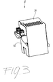
Figure 3 is a perspective view of a first embodiment of a control box of a medium voltage circuit breaker according to the invention; -
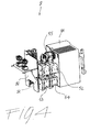
Figure 4 is an exploded perspective view of the control box offigure 3 ; -
Figure 5 is a perspective view of a second embodiment of a control box of a medium voltage circuit breaker according to the invention; -
Figure 6 is a first exploded perspective view of the control box offigure 5 ; -
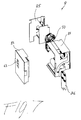
Figure 7 is a second exploded perspective view of the control box offigure 5 . - With reference to the attached figures, a medium voltage circuit breaker according to the invention, designed with the reference number 1, in its more general definition, comprises an
insulating base frame 2, which is conveniently made in one piece of insulating material. - The
insulating base frame 2 supports a pole assembly having, for each phase, an interruption unit housing a fixed contact and a movable contact reciprocally couplable/uncouplable between an open and a closed position (fixed and movable contacts are not shown in the attached drawings). - Normally the circuit breaker 1 is a three-phase circuit breaker and thus comprises three
interruption units 3, 4, and 5 which house corresponding sets of fixed/movable contacts reciprocally couplable/uncouplable between an open and closed position. Fixed and movable contacts can be conventional contacts of known type and therefore will not be described in more details. - Electrical connection of the circuit breaker 1 with the power plant usually comprises, for each phase,
connection plugs interruption units 3, 4, and 5, as well asconnection plugs insulating base frame 2 and electrically connected with thecorresponding interruption units 3, 4, and 5. - The circuit breaker according to the invention further comprises an
actuator 6 to actuate the opening and closing operation of said circuit breaker. Theactuator 6 normally comprises an actuating mechanism connected to the movable contact assembly through a kinematic chain (not shown). For the purposes of the present invention, the actuator can be a conventional actuator of known type and therefore will not be described in more details, being known per se. - One of the characterizing features of the medium voltage circuit breaker 1 of the present invention is that said circuit breaker comprises a control and
diagnostic unit 7 which conveniently comprises acontrol box 8. - The
control box 8 substantially consists of acasing 81 which houses a plurality ofaccessory devices - Thus, the medium voltage circuit breaker 1 of the invention has the great advantage that all auxiliaries, or at least a good number of them, are grouped together inside the
casing 81 of thecontrol box 8. The whole assembly of thecontrol box 8 can therefore be pre-assembled and pre-tested before being positioned in theinsulating base frame 2, together with theinterruption units 3, 4, and 5, theactuator 6 and the kinematic chain, with a consistent reduction of production times and costs. - Preferably, as shown in
figure 1 and2 , thecontrol box 8, the actuating mechanism of theactuator 6 and the kinematic chain can be conveniently covered by acasing 25 which is mechanically coupled (e.g. by clipping) to the insulatingbase frame 2. In the above mentioned figures, thecasing 25 has been partially cut-out in order to show the positioning of thecontrol box 8 onto the insulatingbase frame 2 - With reference to
figures 3 to 8 , preferred embodiments of the medium voltage circuit breaker 1 of the invention foresee that thecontrol box 8 comprises aninsulated casing 81 for housing said plurality ofaccessory devices control box 8 then further comprises acover 82 which is couplable to saidinsulated casing 81, in order to realize an enclosed environment. - In order to minimize the assembly procedures, the
control box 8 conveniently comprises co-moulded wirings for plug-in connection of said plurality ofaccessory devices auxiliary devices auxiliary devices control box 8. - Preferably, in order to make quicker and simpler also the electrical connection of the
control box 8 with the circuit breaker 1, saidcontrol box 8 can conveniently comprise at least a co-moulded connection of the plug-socket type for connection to said circuit breaker 1. In practice, a connection, e.g. a socket, can be prearranged on thecontrol box 8, said socket being couplable with a corresponding plug on the circuit breaker side. It is also possible to have plug connection pre-arranged on thecontrol box 8, said plug being couplable with a corresponding socket on the circuit breaker side - Preferably, in order to further minimize the assembly procedures of the medium voltage circuit breaker 1 of the invention, said insulating
base frame 2 comprises a pre-arranged connection, e.g. at least a co-moulded connection of the plug-socket type for connecting to the above-mentioned corresponding plug-socket connection pre-arranged on saidcontrol box 8. - In addition to the mechanical fixing of the
control box 8 onto the insulatingbase frame 2 and the electrical connection thereof with the circuit breaker, thecontrol box 8 can conveniently comprise also amechanical connection 50 with saidactuator 6. As an example, said mechanical connection can be used for transmitting motion between one of the auxiliary devices (e.g. a spring charging motor) and theactuator 6 or to detect parameters of the main operating shaft of the actuator, e.g. position and/or speed and/or acceleration of the main operating shaft. - In a preferred embodiment of the medium voltage circuit breaker 1 according to the invention, said
control box 8 advantageously comprises a localhuman machine interface 63 for signaling the status and/or malfunctioning conditions of said circuit breaker 1. For instance, the localhuman machine interface 63 can consist of a number of LEDs properly positioned on the exterior of thecontrol box 8 so as to be visible by a user. - In such a case, as shown in the attached
figure 5 to 7 , said localhuman machine interface 63 is preferably positioned on saidcover 82 of saidcontrol box 8. - For what concerns the typology of the
auxiliary devices control box 8. - For instance, said
auxiliary devices more coils auxiliary contacts 86 and/or aspring charging motor 55. - As an example, said coils 51, 52, 53 and 54 can comprise one or more of the following coils: opening, closing, shunt, undervoltage or blocking coils.
- According to a particularly preferred embodiment of the Medium Voltage circuit breaker according to the invention, least one of said coils 51, 52, 53 and 54 is able to run with different voltages and perform different functions. In other words, by properly controlling one or more of said coils it is possible to use said coils for different purposes, thereby minimizing the number of coils required and consequently reducing the manufacturing costs.
- With reference to
figure 5 to 7 , thecontrol box 8 preferably comprises also an electronic device that handles the various components and allows a self-diagnostic to be carried out. - In such a case, said
control box 8 preferably comprises aremovable portion 82 positioned on saidcasing 81, saidremovable portion 82 comprising an electronic board including diagnostic and control electronics. - The presence of diagnostic and control electronics allows to perform a number of functions, such as: control of the trip coils, control of the spring charging motor, control of the truck motor, detection of malfunctioning with local or remote alarms, monitoring the base parameters of the drive to determine the aging of the components thereof, interface with voltage and current sensors, etc.
- It is clear from the above that medium voltage circuit breaker of the invention have a number of advantages with respect to medium voltage circuit breaker of known type.
- In particular, instead of having the auxiliary devices separately assembled and wired, in the circuit breaker of the present invention the auxiliary devices are grouped together inside the
casing 81 of thecontrol box 8. The whole assembly of thecontrol box 8 can therefore be pre-assembled and pre-tested before being positioned in the insulatingbase frame 2. - With the above solution it is possible to optimize the needs, e.g. minimize the number of coils, obtain a wider voltage range, have new auxiliary contacts, etc.
- Also, the use of the insulating
base frame 2 and of thecontrol box 8 has a number of advantages with respect to conventional circuit breaker with an assembled base frame made of many metallic parts. - As a first advantage, the manufacturing process is greatly simplified since, in practice, the various components of the circuit breaker (interruption units, actuator, control box) are fixed to the insulating
base frame 2, e.g. using screw means, said insulatingbase frame 2 being advantageously made in one piece. - Thus, in order to assembly the various components, it is sufficient to position the
interruption units 3, 4, and 5, theactuator 6 and thecontrol box 8 inside the insulatingbase frame 2. Then, fixing means, for instance screw means, can be used to fix thepoles interruption units 3, 4, and 5, theactuator 6 and thecontrol box 8 to the insulatingbase frame 2. The screw means can be inserted in the corresponding seats of the insulatingbase frame 2, from the bottom wall thereof. Therefore, the assembly process is extremely simple and can be highly automatize, thereby contributing to the reduction of the manufacturing times and costs. - In particular, as explained above, the production process for manufacturing the circuit breaker 1 is greatly simplified with respect to the conventional circuit breaker. As a matter of fact, the various sub-components of the circuit breaker (e.g. pole assembly, actuator, kinematic chain) can be pre-assembled outside the main production line of the circuit breaker. The sub-components are then fixed to the insulating base frame in a very quick and highly automatized way.
- The medium voltage circuit breaker thus conceived may undergo numerous modifications and come in several variants, all coming within the scope of the inventive concept. Moreover, all the component parts described herein may be substituted by other, technically equivalent elements. In practice, the component materials and dimensions of the device may be of any nature, according to need and the state of the art.
Claims (12)
- A Medium Voltage circuit breaker (1) characterized in that it comprises an insulating base frame (2) supporting:- a pole assembly having, for each phase, an interruption unit (3, 4, 5) housing a fixed contact and a movable contact reciprocally couplable/uncouplable between an open and a closed position;- an actuator (6) to actuate the opening and closing operation of said circuit breaker (1); and,- a control and diagnostic unit (7) comprising a control box (8) having a casing (81) housing a plurality of accessory devices (50, 51, 52, 53, 54, 55, 86) of said circuit breaker (1).
- The Medium Voltage circuit breaker (1) according to claim 1, characterized in that said control box (8) comprises an insulated casing (81) for housing said plurality of accessory devices (50, 51, 52, 53, 54, 55, 86) and a cover (82) couplable to said insulated casing (81).
- The Medium Voltage circuit breaker (1) according to claim 1 or 2, characterized in that said control box (8) comprises co-moulded wirings for plug-in connection of said plurality of accessory devices (50, 51, 52, 53, 54, 55, 86).
- The Medium Voltage circuit breaker (1) according to one or more of the previous claims, characterized in that said control box (8) comprises at least a co-moulded connection of the plug-socket type for connection to said circuit breaker (1).
- The Medium Voltage circuit breaker (1) according to claim 4, characterized in that said insulating base frame (2) comprises at least a co-moulded connection of the plug-socket type for connecting to a corresponding plug-socket connection of said control box (8).
- The Medium Voltage circuit breaker (1) according to one or more of the previous claims, characterized in that said control box (8) comprises a mechanical connection (50) with said actuator (6).
- The Medium Voltage circuit breaker (1) according to one or more of the previous claims, characterized in that said control box (8) comprises a local human machine interface (63) for signaling the status and/or malfunctioning conditions of said circuit breaker (1).
- The Medium Voltage circuit breaker (1) according to claim 2 and 7, characterized in that said local human machine interface (63) is positioned on said cover (82) of said control box (8).
- The Medium Voltage circuit breaker (1) according to one or more of the previous claims, characterized in that said auxiliary devices (50, 51, 52, 53, 54, 55, 86) comprises one or more coils (51, 52, 53, 54) and/or one or more pairs of auxiliary contacts (86) and/or a spring charging motor (55).
- The Medium Voltage circuit breaker (1) according to claim 9, characterized in that said coils (51, 52, 53, 54) comprises one or more of the following coils: opening, closing, shunt, undervoltage or blocking coils.
- The Medium Voltage circuit breaker (1) according to claim 9 or 10, characterized in that at least one of said coils (51, 52, 53, 54) is able to run with different voltages and perform different functions.
- The Medium Voltage circuit breaker (1) according to one or more of the previous claims, characterized in that said control box (8) comprises a removable portion (82) positioned inside on casing (81) and comprising an electronic board including diagnostic and control electronics.
Priority Applications (8)
| Application Number | Priority Date | Filing Date | Title |
|---|---|---|---|
| EP10150948A EP2346060B1 (en) | 2010-01-18 | 2010-01-18 | Medium voltage circuit breaker. |
| ES10150948T ES2397075T3 (en) | 2010-01-18 | 2010-01-18 | Medium voltage circuit breaker |
| DK10150948.7T DK2346060T3 (en) | 2010-01-18 | 2010-01-18 | Medium Voltage Circuit Breaker |
| US13/522,615 US8842407B2 (en) | 2010-01-18 | 2010-12-13 | Medium voltage circuit breaker |
| CN201080061709.2A CN102714110B (en) | 2010-01-18 | 2010-12-13 | Medium voltage breaker |
| PCT/EP2010/069478 WO2011085887A1 (en) | 2010-01-18 | 2010-12-13 | Medium voltage circuit breaker |
| BR112012017671A BR112012017671A8 (en) | 2010-01-18 | 2010-12-13 | MEDIUM VOLTAGE CIRCUIT SWITCH |
| RU2012135465/07A RU2560923C2 (en) | 2010-01-18 | 2010-12-13 | Medium voltage circuit breaker |
Applications Claiming Priority (1)
| Application Number | Priority Date | Filing Date | Title |
|---|---|---|---|
| EP10150948A EP2346060B1 (en) | 2010-01-18 | 2010-01-18 | Medium voltage circuit breaker. |
Publications (2)
| Publication Number | Publication Date |
|---|---|
| EP2346060A1 true EP2346060A1 (en) | 2011-07-20 |
| EP2346060B1 EP2346060B1 (en) | 2012-11-07 |
Family
ID=42080582
Family Applications (1)
| Application Number | Title | Priority Date | Filing Date |
|---|---|---|---|
| EP10150948A Active EP2346060B1 (en) | 2010-01-18 | 2010-01-18 | Medium voltage circuit breaker. |
Country Status (8)
| Country | Link |
|---|---|
| US (1) | US8842407B2 (en) |
| EP (1) | EP2346060B1 (en) |
| CN (1) | CN102714110B (en) |
| BR (1) | BR112012017671A8 (en) |
| DK (1) | DK2346060T3 (en) |
| ES (1) | ES2397075T3 (en) |
| RU (1) | RU2560923C2 (en) |
| WO (1) | WO2011085887A1 (en) |
Cited By (1)
| Publication number | Priority date | Publication date | Assignee | Title |
|---|---|---|---|---|
| EP3444833A1 (en) * | 2017-08-14 | 2019-02-20 | ABB Schweiz AG | Auxiliary/control switches kit box for a medium voltage switching device |
Families Citing this family (7)
| Publication number | Priority date | Publication date | Assignee | Title |
|---|---|---|---|---|
| ES2545208T3 (en) * | 2009-12-29 | 2015-09-09 | Abb Technology Ag | Medium voltage circuit breaker |
| ES2537528T3 (en) * | 2012-07-24 | 2015-06-09 | Abb S.P.A. | Enhanced Solid State Switch |
| GB2521135B (en) * | 2013-12-10 | 2017-01-18 | Tavrida Electric Holding Ag | Switching apparatus for electrical power systems |
| USD880435S1 (en) * | 2018-07-02 | 2020-04-07 | Abb Schweiz Ag | Cover plate for switches |
| USD883232S1 (en) * | 2018-12-31 | 2020-05-05 | Abb Schweiz Ag | Switch with a cover plate |
| CN112259421B (en) * | 2020-11-16 | 2024-11-26 | 南京米特科技股份有限公司 | A quick-plug circuit breaker |
| EP4125106A1 (en) * | 2021-07-27 | 2023-02-01 | Abb Schweiz Ag | Monitoring system for a low voltage, medium voltage, or high voltage circuit breaker |
Citations (3)
| Publication number | Priority date | Publication date | Assignee | Title |
|---|---|---|---|---|
| EP0681352A2 (en) * | 1994-04-08 | 1995-11-08 | S&C ELECTRIC COMPANY | Switchgear module and configurations, and method of fabrication and assembly thereof |
| US6930271B1 (en) * | 2004-08-13 | 2005-08-16 | Eaton Corporation | Circuit interrupter including linear actuator and manual pivot member |
| US7201595B1 (en) * | 2006-01-06 | 2007-04-10 | Delphi Technologies, Inc. | Electrical connector body co-molded with cable and peripheral seals |
Family Cites Families (8)
| Publication number | Priority date | Publication date | Assignee | Title |
|---|---|---|---|---|
| US4025883A (en) * | 1975-11-11 | 1977-05-24 | Westinghouse Electric Corporation | Modular integral motor controller |
| US4360857A (en) * | 1980-12-10 | 1982-11-23 | General Electric Company | Modular insulative support base for electrical switchgear |
| US6373358B1 (en) * | 2000-05-09 | 2002-04-16 | Eaton Corporation | Power circuit breaker having molded insulative casing with a dead front |
| US7329813B2 (en) * | 2004-12-08 | 2008-02-12 | Siemens Energy & Automation, Inc. | Modular insulation system |
| JP4606146B2 (en) * | 2004-12-09 | 2011-01-05 | 三菱電機株式会社 | Switchgear |
| US7576957B2 (en) * | 2006-05-01 | 2009-08-18 | Eaton Corporation | Circuit interrupter including point-on-wave controller and voltage sensors |
| US7696447B2 (en) * | 2007-06-01 | 2010-04-13 | Eaton Corporation | Electrical switching apparatus and stored energy assembly therefor |
| ES2538815T3 (en) * | 2008-05-16 | 2015-06-24 | Suncore Photovoltaics Incorporated | Photovoltaic solar panel concentration |
-
2010
- 2010-01-18 ES ES10150948T patent/ES2397075T3/en active Active
- 2010-01-18 DK DK10150948.7T patent/DK2346060T3/en active
- 2010-01-18 EP EP10150948A patent/EP2346060B1/en active Active
- 2010-12-13 US US13/522,615 patent/US8842407B2/en active Active
- 2010-12-13 CN CN201080061709.2A patent/CN102714110B/en active Active
- 2010-12-13 WO PCT/EP2010/069478 patent/WO2011085887A1/en not_active Ceased
- 2010-12-13 BR BR112012017671A patent/BR112012017671A8/en not_active Application Discontinuation
- 2010-12-13 RU RU2012135465/07A patent/RU2560923C2/en active
Patent Citations (3)
| Publication number | Priority date | Publication date | Assignee | Title |
|---|---|---|---|---|
| EP0681352A2 (en) * | 1994-04-08 | 1995-11-08 | S&C ELECTRIC COMPANY | Switchgear module and configurations, and method of fabrication and assembly thereof |
| US6930271B1 (en) * | 2004-08-13 | 2005-08-16 | Eaton Corporation | Circuit interrupter including linear actuator and manual pivot member |
| US7201595B1 (en) * | 2006-01-06 | 2007-04-10 | Delphi Technologies, Inc. | Electrical connector body co-molded with cable and peripheral seals |
Cited By (3)
| Publication number | Priority date | Publication date | Assignee | Title |
|---|---|---|---|---|
| EP3444833A1 (en) * | 2017-08-14 | 2019-02-20 | ABB Schweiz AG | Auxiliary/control switches kit box for a medium voltage switching device |
| WO2019034350A1 (en) * | 2017-08-14 | 2019-02-21 | Abb Schweiz Ag | Auxiliary/control switches kit box for a medium voltage switching device. |
| US10998156B2 (en) | 2017-08-14 | 2021-05-04 | Abb Schweiz Ag | Auxiliary/control switches kit box for a medium voltage switching device |
Also Published As
| Publication number | Publication date |
|---|---|
| BR112012017671A8 (en) | 2017-12-19 |
| EP2346060B1 (en) | 2012-11-07 |
| BR112012017671A2 (en) | 2016-04-19 |
| US8842407B2 (en) | 2014-09-23 |
| DK2346060T3 (en) | 2013-02-18 |
| CN102714110B (en) | 2015-08-19 |
| CN102714110A (en) | 2012-10-03 |
| US20120320487A1 (en) | 2012-12-20 |
| WO2011085887A1 (en) | 2011-07-21 |
| RU2012135465A (en) | 2014-02-27 |
| ES2397075T3 (en) | 2013-03-04 |
| RU2560923C2 (en) | 2015-08-20 |
Similar Documents
| Publication | Publication Date | Title |
|---|---|---|
| US8842407B2 (en) | Medium voltage circuit breaker | |
| CN101211728B (en) | Earth leakage circuit breaker | |
| US9111707B2 (en) | Installation switching device with a current sensing unit | |
| CA2911363C (en) | Circuit breaker including remote operation circuit | |
| CN215911371U (en) | Data exchange equipment and device | |
| US8890011B2 (en) | Medium voltage circuit breaker | |
| US9852851B2 (en) | Molded case circuit breaker with current sensing unit | |
| WO2009105184A1 (en) | Multi-pole armature interlock for circuit breakers | |
| CN104701101A (en) | Cover assembly for circuit breaker, circuit breaker having the same, and method | |
| JPWO2005062325A1 (en) | Disconnector | |
| JP2009506487A (en) | Wiring device with electromagnetic switchgear | |
| KR100934859B1 (en) | Electronic Circuit Meter with Circuit Breaker | |
| CN109728644B (en) | Switching device and control method | |
| EP1975965B1 (en) | Electrical switching apparatus, and accessory module and electrical conductor mount therefor | |
| RU2660912C2 (en) | Automatic switch in molded case and method for its assembly | |
| CA2911373A1 (en) | Circuit breaker panel including remotely operated circuit breaker | |
| US4958256A (en) | Flame-proof electric device | |
| CN112670943B (en) | Protection device for alternating current electrical equipment | |
| KR100966446B1 (en) | Ground switch of gas insulated switchgear | |
| CN103165334B (en) | High voltage switching assembly | |
| US20150016084A1 (en) | Breaker secondary terminal block isolation chamber | |
| EP4456110A1 (en) | Accessory device for low-voltage electrical installations | |
| US20150214716A1 (en) | Electrical protective arrangement for an electrical installation, and associated method | |
| RU2814214C2 (en) | Protection device for alternating current electrical installation | |
| KR102071551B1 (en) | Electronic Trip Device of Molded Case Circuit Breaker |
Legal Events
| Date | Code | Title | Description |
|---|---|---|---|
| PUAI | Public reference made under article 153(3) epc to a published international application that has entered the european phase |
Free format text: ORIGINAL CODE: 0009012 |
|
| AK | Designated contracting states |
Kind code of ref document: A1 Designated state(s): AT BE BG CH CY CZ DE DK EE ES FI FR GB GR HR HU IE IS IT LI LT LU LV MC MK MT NL NO PL PT RO SE SI SK SM TR |
|
| 17P | Request for examination filed |
Effective date: 20120112 |
|
| GRAP | Despatch of communication of intention to grant a patent |
Free format text: ORIGINAL CODE: EPIDOSNIGR1 |
|
| GRAS | Grant fee paid |
Free format text: ORIGINAL CODE: EPIDOSNIGR3 |
|
| GRAA | (expected) grant |
Free format text: ORIGINAL CODE: 0009210 |
|
| AK | Designated contracting states |
Kind code of ref document: B1 Designated state(s): AT BE BG CH CY CZ DE DK EE ES FI FR GB GR HR HU IE IS IT LI LT LU LV MC MK MT NL NO PL PT RO SE SI SK SM TR |
|
| REG | Reference to a national code |
Ref country code: GB Ref legal event code: FG4D |
|
| REG | Reference to a national code |
Ref country code: AT Ref legal event code: REF Ref document number: 583291 Country of ref document: AT Kind code of ref document: T Effective date: 20121115 Ref country code: CH Ref legal event code: EP |
|
| REG | Reference to a national code |
Ref country code: IE Ref legal event code: FG4D |
|
| REG | Reference to a national code |
Ref country code: DE Ref legal event code: R096 Ref document number: 602010003476 Country of ref document: DE Effective date: 20130103 |
|
| REG | Reference to a national code |
Ref country code: DK Ref legal event code: T3 |
|
| REG | Reference to a national code |
Ref country code: ES Ref legal event code: FG2A Ref document number: 2397075 Country of ref document: ES Kind code of ref document: T3 Effective date: 20130304 |
|
| REG | Reference to a national code |
Ref country code: AT Ref legal event code: MK05 Ref document number: 583291 Country of ref document: AT Kind code of ref document: T Effective date: 20121107 |
|
| REG | Reference to a national code |
Ref country code: NL Ref legal event code: VDEP Effective date: 20121107 |
|
| REG | Reference to a national code |
Ref country code: LT Ref legal event code: MG4D |
|
| PG25 | Lapsed in a contracting state [announced via postgrant information from national office to epo] |
Ref country code: LT Free format text: LAPSE BECAUSE OF FAILURE TO SUBMIT A TRANSLATION OF THE DESCRIPTION OR TO PAY THE FEE WITHIN THE PRESCRIBED TIME-LIMIT Effective date: 20121107 Ref country code: HR Free format text: LAPSE BECAUSE OF FAILURE TO SUBMIT A TRANSLATION OF THE DESCRIPTION OR TO PAY THE FEE WITHIN THE PRESCRIBED TIME-LIMIT Effective date: 20121107 Ref country code: NL Free format text: LAPSE BECAUSE OF FAILURE TO SUBMIT A TRANSLATION OF THE DESCRIPTION OR TO PAY THE FEE WITHIN THE PRESCRIBED TIME-LIMIT Effective date: 20121107 Ref country code: IS Free format text: LAPSE BECAUSE OF FAILURE TO SUBMIT A TRANSLATION OF THE DESCRIPTION OR TO PAY THE FEE WITHIN THE PRESCRIBED TIME-LIMIT Effective date: 20130307 Ref country code: SE Free format text: LAPSE BECAUSE OF FAILURE TO SUBMIT A TRANSLATION OF THE DESCRIPTION OR TO PAY THE FEE WITHIN THE PRESCRIBED TIME-LIMIT Effective date: 20121107 Ref country code: FI Free format text: LAPSE BECAUSE OF FAILURE TO SUBMIT A TRANSLATION OF THE DESCRIPTION OR TO PAY THE FEE WITHIN THE PRESCRIBED TIME-LIMIT Effective date: 20121107 Ref country code: NO Free format text: LAPSE BECAUSE OF FAILURE TO SUBMIT A TRANSLATION OF THE DESCRIPTION OR TO PAY THE FEE WITHIN THE PRESCRIBED TIME-LIMIT Effective date: 20130207 |
|
| PG25 | Lapsed in a contracting state [announced via postgrant information from national office to epo] |
Ref country code: PT Free format text: LAPSE BECAUSE OF FAILURE TO SUBMIT A TRANSLATION OF THE DESCRIPTION OR TO PAY THE FEE WITHIN THE PRESCRIBED TIME-LIMIT Effective date: 20130307 Ref country code: GR Free format text: LAPSE BECAUSE OF FAILURE TO SUBMIT A TRANSLATION OF THE DESCRIPTION OR TO PAY THE FEE WITHIN THE PRESCRIBED TIME-LIMIT Effective date: 20130208 Ref country code: PL Free format text: LAPSE BECAUSE OF FAILURE TO SUBMIT A TRANSLATION OF THE DESCRIPTION OR TO PAY THE FEE WITHIN THE PRESCRIBED TIME-LIMIT Effective date: 20121107 Ref country code: LV Free format text: LAPSE BECAUSE OF FAILURE TO SUBMIT A TRANSLATION OF THE DESCRIPTION OR TO PAY THE FEE WITHIN THE PRESCRIBED TIME-LIMIT Effective date: 20121107 Ref country code: SI Free format text: LAPSE BECAUSE OF FAILURE TO SUBMIT A TRANSLATION OF THE DESCRIPTION OR TO PAY THE FEE WITHIN THE PRESCRIBED TIME-LIMIT Effective date: 20121107 |
|
| PG25 | Lapsed in a contracting state [announced via postgrant information from national office to epo] |
Ref country code: AT Free format text: LAPSE BECAUSE OF FAILURE TO SUBMIT A TRANSLATION OF THE DESCRIPTION OR TO PAY THE FEE WITHIN THE PRESCRIBED TIME-LIMIT Effective date: 20121107 |
|
| PG25 | Lapsed in a contracting state [announced via postgrant information from national office to epo] |
Ref country code: SK Free format text: LAPSE BECAUSE OF FAILURE TO SUBMIT A TRANSLATION OF THE DESCRIPTION OR TO PAY THE FEE WITHIN THE PRESCRIBED TIME-LIMIT Effective date: 20121107 Ref country code: BG Free format text: LAPSE BECAUSE OF FAILURE TO SUBMIT A TRANSLATION OF THE DESCRIPTION OR TO PAY THE FEE WITHIN THE PRESCRIBED TIME-LIMIT Effective date: 20130207 Ref country code: EE Free format text: LAPSE BECAUSE OF FAILURE TO SUBMIT A TRANSLATION OF THE DESCRIPTION OR TO PAY THE FEE WITHIN THE PRESCRIBED TIME-LIMIT Effective date: 20121107 |
|
| PG25 | Lapsed in a contracting state [announced via postgrant information from national office to epo] |
Ref country code: MC Free format text: LAPSE BECAUSE OF NON-PAYMENT OF DUE FEES Effective date: 20130131 Ref country code: RO Free format text: LAPSE BECAUSE OF FAILURE TO SUBMIT A TRANSLATION OF THE DESCRIPTION OR TO PAY THE FEE WITHIN THE PRESCRIBED TIME-LIMIT Effective date: 20121107 |
|
| PLBE | No opposition filed within time limit |
Free format text: ORIGINAL CODE: 0009261 |
|
| STAA | Information on the status of an ep patent application or granted ep patent |
Free format text: STATUS: NO OPPOSITION FILED WITHIN TIME LIMIT |
|
| 26N | No opposition filed |
Effective date: 20130808 |
|
| REG | Reference to a national code |
Ref country code: IE Ref legal event code: MM4A |
|
| PG25 | Lapsed in a contracting state [announced via postgrant information from national office to epo] |
Ref country code: CY Free format text: LAPSE BECAUSE OF FAILURE TO SUBMIT A TRANSLATION OF THE DESCRIPTION OR TO PAY THE FEE WITHIN THE PRESCRIBED TIME-LIMIT Effective date: 20121107 |
|
| REG | Reference to a national code |
Ref country code: DE Ref legal event code: R097 Ref document number: 602010003476 Country of ref document: DE Effective date: 20130808 |
|
| PG25 | Lapsed in a contracting state [announced via postgrant information from national office to epo] |
Ref country code: IE Free format text: LAPSE BECAUSE OF NON-PAYMENT OF DUE FEES Effective date: 20130118 |
|
| PG25 | Lapsed in a contracting state [announced via postgrant information from national office to epo] |
Ref country code: MT Free format text: LAPSE BECAUSE OF FAILURE TO SUBMIT A TRANSLATION OF THE DESCRIPTION OR TO PAY THE FEE WITHIN THE PRESCRIBED TIME-LIMIT Effective date: 20121107 |
|
| REG | Reference to a national code |
Ref country code: CH Ref legal event code: PL |
|
| PG25 | Lapsed in a contracting state [announced via postgrant information from national office to epo] |
Ref country code: CH Free format text: LAPSE BECAUSE OF NON-PAYMENT OF DUE FEES Effective date: 20140131 Ref country code: LI Free format text: LAPSE BECAUSE OF NON-PAYMENT OF DUE FEES Effective date: 20140131 |
|
| PG25 | Lapsed in a contracting state [announced via postgrant information from national office to epo] |
Ref country code: SM Free format text: LAPSE BECAUSE OF FAILURE TO SUBMIT A TRANSLATION OF THE DESCRIPTION OR TO PAY THE FEE WITHIN THE PRESCRIBED TIME-LIMIT Effective date: 20121107 |
|
| PG25 | Lapsed in a contracting state [announced via postgrant information from national office to epo] |
Ref country code: TR Free format text: LAPSE BECAUSE OF FAILURE TO SUBMIT A TRANSLATION OF THE DESCRIPTION OR TO PAY THE FEE WITHIN THE PRESCRIBED TIME-LIMIT Effective date: 20121107 |
|
| PG25 | Lapsed in a contracting state [announced via postgrant information from national office to epo] |
Ref country code: LU Free format text: LAPSE BECAUSE OF NON-PAYMENT OF DUE FEES Effective date: 20130118 Ref country code: MK Free format text: LAPSE BECAUSE OF FAILURE TO SUBMIT A TRANSLATION OF THE DESCRIPTION OR TO PAY THE FEE WITHIN THE PRESCRIBED TIME-LIMIT Effective date: 20121107 Ref country code: HU Free format text: LAPSE BECAUSE OF FAILURE TO SUBMIT A TRANSLATION OF THE DESCRIPTION OR TO PAY THE FEE WITHIN THE PRESCRIBED TIME-LIMIT; INVALID AB INITIO Effective date: 20100118 |
|
| REG | Reference to a national code |
Ref country code: FR Ref legal event code: PLFP Year of fee payment: 7 |
|
| REG | Reference to a national code |
Ref country code: FR Ref legal event code: PLFP Year of fee payment: 8 |
|
| REG | Reference to a national code |
Ref country code: DE Ref legal event code: R082 Ref document number: 602010003476 Country of ref document: DE Representative=s name: KUHNEN & WACKER PATENT- UND RECHTSANWALTSBUERO, DE Ref country code: DE Ref legal event code: R081 Ref document number: 602010003476 Country of ref document: DE Owner name: ABB SCHWEIZ AG, CH Free format text: FORMER OWNER: ABB TECHNOLOGY AG, ZUERICH, CH |
|
| REG | Reference to a national code |
Ref country code: ES Ref legal event code: PC2A Owner name: ABB SCHWEIZ AG Effective date: 20171213 |
|
| REG | Reference to a national code |
Ref country code: FR Ref legal event code: PLFP Year of fee payment: 9 |
|
| REG | Reference to a national code |
Ref country code: BE Ref legal event code: PD Owner name: ABB SCHWEIZ AG; CH Free format text: DETAILS ASSIGNMENT: CHANGE OF OWNER(S), CESSION; FORMER OWNER NAME: ABB TECHNOLOGY AG Effective date: 20180112 |
|
| REG | Reference to a national code |
Ref country code: GB Ref legal event code: 732E Free format text: REGISTERED BETWEEN 20180426 AND 20180502 |
|
| REG | Reference to a national code |
Ref country code: FR Ref legal event code: TP Owner name: ABB SCHWEIZ AG, CH Effective date: 20180912 |
|
| PGFP | Annual fee paid to national office [announced via postgrant information from national office to epo] |
Ref country code: RS Payment date: 20190129 Year of fee payment: 9 |
|
| REG | Reference to a national code |
Ref country code: DK Ref legal event code: EBP Effective date: 20200131 |
|
| PG25 | Lapsed in a contracting state [announced via postgrant information from national office to epo] |
Ref country code: DK Free format text: LAPSE BECAUSE OF NON-PAYMENT OF DUE FEES Effective date: 20200131 |
|
| PGFP | Annual fee paid to national office [announced via postgrant information from national office to epo] |
Ref country code: GB Payment date: 20260123 Year of fee payment: 17 |
|
| PGFP | Annual fee paid to national office [announced via postgrant information from national office to epo] |
Ref country code: ES Payment date: 20260227 Year of fee payment: 17 |
|
| PGFP | Annual fee paid to national office [announced via postgrant information from national office to epo] |
Ref country code: DE Payment date: 20260121 Year of fee payment: 17 |
|
| PGFP | Annual fee paid to national office [announced via postgrant information from national office to epo] |
Ref country code: BE Payment date: 20260121 Year of fee payment: 17 Ref country code: IT Payment date: 20260126 Year of fee payment: 17 |
|
| PGFP | Annual fee paid to national office [announced via postgrant information from national office to epo] |
Ref country code: FR Payment date: 20260123 Year of fee payment: 17 |
|
| PGFP | Annual fee paid to national office [announced via postgrant information from national office to epo] |
Ref country code: CZ Payment date: 20260114 Year of fee payment: 17 |