EP2345896A1 - Liquid chromatography device and liquid chromatography - Google Patents
Liquid chromatography device and liquid chromatography Download PDFInfo
- Publication number
- EP2345896A1 EP2345896A1 EP09819171A EP09819171A EP2345896A1 EP 2345896 A1 EP2345896 A1 EP 2345896A1 EP 09819171 A EP09819171 A EP 09819171A EP 09819171 A EP09819171 A EP 09819171A EP 2345896 A1 EP2345896 A1 EP 2345896A1
- Authority
- EP
- European Patent Office
- Prior art keywords
- eluent
- flow path
- directional valve
- path directional
- column
- Prior art date
- Legal status (The legal status is an assumption and is not a legal conclusion. Google has not performed a legal analysis and makes no representation as to the accuracy of the status listed.)
- Granted
Links
Images





Classifications
-
- G—PHYSICS
- G01—MEASURING; TESTING
- G01N—INVESTIGATING OR ANALYSING MATERIALS BY DETERMINING THEIR CHEMICAL OR PHYSICAL PROPERTIES
- G01N30/00—Investigating or analysing materials by separation into components using adsorption, absorption or similar phenomena or using ion-exchange, e.g. chromatography or field flow fractionation
- G01N30/02—Column chromatography
- G01N30/04—Preparation or injection of sample to be analysed
- G01N30/24—Automatic injection systems
-
- G—PHYSICS
- G01—MEASURING; TESTING
- G01N—INVESTIGATING OR ANALYSING MATERIALS BY DETERMINING THEIR CHEMICAL OR PHYSICAL PROPERTIES
- G01N30/00—Investigating or analysing materials by separation into components using adsorption, absorption or similar phenomena or using ion-exchange, e.g. chromatography or field flow fractionation
- G01N30/02—Column chromatography
- G01N30/26—Conditioning of the fluid carrier; Flow patterns
-
- G—PHYSICS
- G01—MEASURING; TESTING
- G01N—INVESTIGATING OR ANALYSING MATERIALS BY DETERMINING THEIR CHEMICAL OR PHYSICAL PROPERTIES
- G01N30/00—Investigating or analysing materials by separation into components using adsorption, absorption or similar phenomena or using ion-exchange, e.g. chromatography or field flow fractionation
- G01N30/02—Column chromatography
- G01N30/88—Integrated analysis systems specially adapted therefor, not covered by a single one of the groups G01N30/04 - G01N30/86
-
- G—PHYSICS
- G01—MEASURING; TESTING
- G01N—INVESTIGATING OR ANALYSING MATERIALS BY DETERMINING THEIR CHEMICAL OR PHYSICAL PROPERTIES
- G01N33/00—Investigating or analysing materials by specific methods not covered by groups G01N1/00 - G01N31/00
- G01N33/48—Biological material, e.g. blood, urine; Haemocytometers
- G01N33/50—Chemical analysis of biological material, e.g. blood, urine; Testing involving biospecific ligand binding methods; Immunological testing
- G01N33/72—Chemical analysis of biological material, e.g. blood, urine; Testing involving biospecific ligand binding methods; Immunological testing involving blood pigments, e.g. haemoglobin, bilirubin or other porphyrins; involving occult blood
-
- B—PERFORMING OPERATIONS; TRANSPORTING
- B01—PHYSICAL OR CHEMICAL PROCESSES OR APPARATUS IN GENERAL
- B01D—SEPARATION
- B01D15/00—Separating processes involving the treatment of liquids with solid sorbents; Apparatus therefor
- B01D15/08—Selective adsorption, e.g. chromatography
- B01D15/10—Selective adsorption, e.g. chromatography characterised by constructional or operational features
- B01D15/16—Selective adsorption, e.g. chromatography characterised by constructional or operational features relating to the conditioning of the fluid carrier
-
- G—PHYSICS
- G01—MEASURING; TESTING
- G01N—INVESTIGATING OR ANALYSING MATERIALS BY DETERMINING THEIR CHEMICAL OR PHYSICAL PROPERTIES
- G01N30/00—Investigating or analysing materials by separation into components using adsorption, absorption or similar phenomena or using ion-exchange, e.g. chromatography or field flow fractionation
- G01N30/02—Column chromatography
- G01N30/04—Preparation or injection of sample to be analysed
- G01N30/16—Injection
- G01N30/20—Injection using a sampling valve
- G01N2030/201—Injection using a sampling valve multiport valves, i.e. having more than two ports
-
- G—PHYSICS
- G01—MEASURING; TESTING
- G01N—INVESTIGATING OR ANALYSING MATERIALS BY DETERMINING THEIR CHEMICAL OR PHYSICAL PROPERTIES
- G01N30/00—Investigating or analysing materials by separation into components using adsorption, absorption or similar phenomena or using ion-exchange, e.g. chromatography or field flow fractionation
- G01N30/02—Column chromatography
- G01N30/04—Preparation or injection of sample to be analysed
- G01N30/16—Injection
- G01N30/20—Injection using a sampling valve
- G01N2030/202—Injection using a sampling valve rotary valves
-
- G—PHYSICS
- G01—MEASURING; TESTING
- G01N—INVESTIGATING OR ANALYSING MATERIALS BY DETERMINING THEIR CHEMICAL OR PHYSICAL PROPERTIES
- G01N30/00—Investigating or analysing materials by separation into components using adsorption, absorption or similar phenomena or using ion-exchange, e.g. chromatography or field flow fractionation
- G01N30/02—Column chromatography
- G01N30/04—Preparation or injection of sample to be analysed
- G01N30/16—Injection
- G01N30/20—Injection using a sampling valve
- G01N2030/207—Injection using a sampling valve with metering cavity, e.g. sample loop
-
- G—PHYSICS
- G01—MEASURING; TESTING
- G01N—INVESTIGATING OR ANALYSING MATERIALS BY DETERMINING THEIR CHEMICAL OR PHYSICAL PROPERTIES
- G01N30/00—Investigating or analysing materials by separation into components using adsorption, absorption or similar phenomena or using ion-exchange, e.g. chromatography or field flow fractionation
- G01N30/02—Column chromatography
- G01N30/88—Integrated analysis systems specially adapted therefor, not covered by a single one of the groups G01N30/04 - G01N30/86
- G01N2030/8809—Integrated analysis systems specially adapted therefor, not covered by a single one of the groups G01N30/04 - G01N30/86 analysis specially adapted for the sample
- G01N2030/8813—Integrated analysis systems specially adapted therefor, not covered by a single one of the groups G01N30/04 - G01N30/86 analysis specially adapted for the sample biological materials
- G01N2030/8822—Integrated analysis systems specially adapted therefor, not covered by a single one of the groups G01N30/04 - G01N30/86 analysis specially adapted for the sample biological materials involving blood
-
- G—PHYSICS
- G01—MEASURING; TESTING
- G01N—INVESTIGATING OR ANALYSING MATERIALS BY DETERMINING THEIR CHEMICAL OR PHYSICAL PROPERTIES
- G01N30/00—Investigating or analysing materials by separation into components using adsorption, absorption or similar phenomena or using ion-exchange, e.g. chromatography or field flow fractionation
- G01N30/02—Column chromatography
- G01N30/26—Conditioning of the fluid carrier; Flow patterns
- G01N30/28—Control of physical parameters of the fluid carrier
- G01N30/34—Control of physical parameters of the fluid carrier of fluid composition, e.g. gradient
-
- G—PHYSICS
- G01—MEASURING; TESTING
- G01N—INVESTIGATING OR ANALYSING MATERIALS BY DETERMINING THEIR CHEMICAL OR PHYSICAL PROPERTIES
- G01N30/00—Investigating or analysing materials by separation into components using adsorption, absorption or similar phenomena or using ion-exchange, e.g. chromatography or field flow fractionation
- G01N30/02—Column chromatography
- G01N30/62—Detectors specially adapted therefor
- G01N30/74—Optical detectors
Definitions
- the present invention relates to a liquid chromatography apparatus and liquid chromatography used in blood testing, for example.
- FIG. 14 shows an example of a conventional liquid chromatography apparatus (see, for example, Patent Document 1).
- a liquid chromatography apparatus X shown in this drawing is provided with a sample preparation unit 91, a flow path directional valve 92, a manifold 93, a feed pump 94, an analysis unit 95 and a controller 96.
- the sample preparation unit 91 produces a sample by diluting a sample S such as blood with a diluent Ld. A fixed amount of this sample is accumulated in an injection loop 92b of the flow path directional valve 92.
- the analysis unit 95 has a pre-filter 95a, a column 95b and a photometric unit 95c.
- an eluent La is fed from the manifold 93 by the feed pump 94.
- This eluent La is supplied to the column 95b through the flow path directional valve 92.
- the sample is desorbed by the eluent La and separated into each component within the column 95b.
- the photometric unit 95c is able to analyze each separated component by, for example, measuring absorbance.
- the controller 96 controls driving of the sample preparation unit 91, the flow path directional valve 92, the manifold 93 and the analysis unit 95.
- An eluent Lb is supplied from the manifold 93 to the column 95b through the flow path directional valve 92 for the purpose of washing away these other components.
- An eluent having, for example, a higher salt concentration than the eluent La is used for the eluent Lb.
- An eluent Lc is supplied from the manifold 93 to the column 95b through the flow path directional valve 92 in order to adjust the salt concentration.
- An eluent having a lower salt concentration than the eluents La and Lb is used for the eluent Lc.
- the salt concentration that was increased as a result of supplying the eluent Lb is lowered.
- the salt concentration of the column 95b can subsequently be made to be a salt concentration suitable for analysis by again supplying the eluent La.
- hysteresis of a salt concentration Ds of the column 95b to which is sequentially supplied the eluents La, Lb and Lc is shown in FIG. 15 .
- the eluent is respectively switched from the eluent La to the eluent Lb at a time T1, from the eluent Lb to the eluent Lc at a time T2, and from the eluent Lc to the eluent La at a time T3.
- This switching of the eluents La, Lb and Lc is carried out by the manifold 93.
- an object of the present invention is to provide a liquid chromatography apparatus and liquid chromatography that are able to shorten analysis time and reduce eluent consumption.
- a liquid chromatography apparatus provided by a first aspect of the present invention is provided with: a sample preparation unit for preparing a sample from a specimen; a column for separating components of the sample, an eluent supplier for supplying as a mobile phase two or more types of eluent to the column; a first flow path directional valve capable of introducing a fixed amount of the sample to the column and capable of introducing the eluent to the column; an analyzer for analyzing a test solution composed of the sample components separated by the column and the eluent; and a controller for controlling operation of the sample preparation unit; the eluent supplier; the first flow path directional valve and the analyzer, wherein the eluent supplier supplies two or more types of eluent to the first flow path directional valve in an unmixed state.
- the first and second flow path directional valves of the present invention include injection valves, directional valves such as a 3-way valve, 4-way valve, 5-way valve or 6-way valve, piston valves, plug valves, control valves and Y valves, and have a structure that enables precise control without allowing mixing of a plurality of eluents.
- the eluent supplier is provided with a second flow path directional valve that is able to supply first and second eluents mutually supplied to separate ports to the first flow path directional valve, and the controller carries out control so that at least a portion of the fixed amount of the second eluent accumulated in the second flow path directional valve and the first eluent subsequently introduced into the second flow path directional valve from a port different from that of the second eluent are supplied to the column through the first flow path directional valve either during or after analysis of the test solution by supplying the first eluent to the column through the first flow path directional valve.
- control in supplying the second eluent, in a state in which an injection loop for retaining a fixed amount of the second eluent accumulated in the second flow path directional valve is connected to a pathway leading to the first flow path directional valve, control is carried out that continues to supply the first eluent to the injection loop until all of the fixed amount of the second eluent is discharged from the injection loop.
- control in supplying the second eluent, in a state in which an injection loop for retaining the fixed amount of the second eluent accumulated in the second flow path directional valve is connected to a pathway leading to the first flow path directional valve, control is carried out that supplies the first eluent in a state in which a remainder of the second eluent is allowed to remain in the injection loop and a pathway different from the injection loop is connected to the pathway leading to the first flow path directional valve, after the first eluent has been supplied to the injection loop until a portion of a fixed amount of the second eluent is discharged from the injection loop.
- the eluent supplier is provided with a fixed displacement pump that supplies the first eluent to the second flow path directional valve.
- blood is used for the specimen, with an object being to measure glycohemoglobin.
- Liquid chromatography provided by a second aspect of the present invention has: a step of preparing a sample from a specimen; a step of supplying the sample to a column through a first flow path directional valve; a step of supplying as a mobile phase two or more types of eluent to the column through the first flow path directional valve; a step of supplying a test solution composed of components of the sample separated by the column and the eluent to an analyzer; and a step of measuring absorbance of the test solution by the analyzer, wherein the two or more types of eluent are supplied to the first flow path directional valve in an unmixed state.
- a step is further provided for washing the column by supplying to the column at least a portion of a fixed amount of the second eluent accumulated in a second flow path directional valve connected to the first flow path directional valve and the first eluent subsequently introduced into the second flow path directional valve from a port different from that of the second eluent through the first flow path directional valve either during or after the step of measuring absorbance.
- the washing step in a state in which an injection loop for retaining the fixed amount of the second eluent accumulated in the second flow path directional valve is connected to a pathway leading to the first flow path directional valve, the first eluent is continuingly supplied to the injection loop until all of the fixed amount of the second eluent is discharged from the injection loop.
- the washing step in a state in which an injection loop for retaining the fixed amount of the second eluent accumulated in the second flow path directional valve is connected to a pathway leading to the first flow path directional valve, the first eluent is supplied in a state in which a remainder of the second eluent is allowed to remain in the injection loop and a pathway different from the injection loop is connected to the pathway leading to the first flow path directional valve, after the first eluent has been supplied to the injection loop until a portion of a fixed amount of the second eluent is discharged from the injection loop.
- supplying of the first eluent to the second flow path directional valve is carried out by using a fixed displacement pump.
- blood is used for the specimen, with an object being to measure glycohemoglobin.
- FIG. 1 shows an example of a liquid chromatography apparatus according to the present invention.
- a liquid chromatography apparatus A of the present embodiment is provided with a sample preparation unit 1, a flow path directional valve 2, a feeder 3, a flow path directional valve 4, an analysis unit 5 and a controller 6.
- This liquid chromatography apparatus A carries out liquid chromatography on a specimen S such as blood.
- the sample preparation unit 1 produces a sample on which liquid chromatography is to be carried out by diluting a prescribed amount of the specimen S collected from a blood vessel Ts to a prescribed factor with a diluent Ld collected from a bottle Bd.
- the sample preparation unit 1 includes, for example, a needle-shaped nozzle for collecting the specimen S from the blood vessel Ts, a collection tube for collecting the diluent Ld from the bottle Bd, and a stirrer that mixes these.
- the flow path directional valve 2 has, for example, a 6-way valve 21 and an injection loop 22.
- the 6-way valve 21 has ports 21a, 21b, 21c, 21d, 21e and 21f, and rotates freely relative to the injection loop 22.
- the ports 21a, 21b, 21c and 21d and the ports 21e and 21f are respectively linked by mutually independent flow paths.
- the port 21a is connected to a pipe P4
- the port 21b is connected to a pipe P3
- the ports 21c and 21f are connected to the injection loop 22
- the port 21d is connected to a pipe P2
- the port 21e is connected to the sample preparation unit 1 through a pipe P1.
- the injection loop 22 is for accumulating a fixed amount of the sample.
- the volume of the injection loop 22 is made to be, for example, about 3.4 ⁇ L.
- the feeder 3 and the flow path directional valve 4 compose an eluent supplier as referred to in the present invention.
- the feeder 3 is for delivering or feeding an eluent La housed in a bottle Ba to the flow path directional valve 4, and is provided in a pipe P5.
- the feeder 3 is composed of a plunger pump 31 and a damper 32.
- the plunger pump 31 employs a structure provided with a reciprocating plunger and a check valve, and is equivalent to an example of a fixed displacement pump.
- the damper 32 fulfills the function of alleviating pulsation generated by the plunger pump 31.
- the flow path directional valve 4 has, for example, a 6-way valve 41 and an injection loop 42.
- the 6-way valve 41 has ports 41a, 41b, 41c, 41d, 41e and 41f, and rotates freely relative to the injection loop 42.
- the ports 41a, 41b, 41c and 41d and the ports 41e and 41f are respectively linked by mutually independent flow paths.
- the port 41a is connected to the feeder 3 through the pipe P5
- the port 41b is connected to the flow path direction valve 2 through the pipe P3
- the ports 41c and 41f are connected to the injection loop 42
- the port 41d is connected to a pipe P7
- the port 41e is connected to a bottle Bb housing an eluent Lb through a pipe P6.
- the eluent Lb has a higher salt concentration than the eluent La.
- the injection loop 42 is for accumulating a fixed amount of the eluent Lb.
- the volume of the injection loop 42 is made to be, for example, about 142 ⁇ L. This is equivalent to an amount delivered for 5 seconds by the feeder 3.
- the analysis unit 5 is connected to the flow path directional valve 2 through the pipe P4, and is the site where analysis by liquid chromatography is carried out.
- the analysis unit 5 is composed of a pre-filter 51, a column 52 and a photometric unit 53.
- the pre-filter 51 prevents unwanted substances from entering the column 52.
- the column 52 retains a filler for adsorbing the introduced sample. After the sample has been adsorbed onto the filler, when the eluent La is injected into the column 52, the adsorbed sample is desorbed by the eluent La. Moreover, the desorbed sample and the eluent La flow through the column 52 and are discharged as an eluate.
- the photometric unit 53 is composed so as to analyze components of the sample by, for example, measuring absorbance of the eluate flowing from the column 52, and is equivalent to one example of analyzers referred to in the present invention.
- the controller 6 respectively drives and controls the sample preparation unit 1, the flow path directional valve 2, the feeder 3, the flow path directional valve 4 an the analysis unit 5, and is composed of, for example, a CPU, a memory and an interface for transmitting and receiving signals.
- the controller 6 controls processing for carrying out analysis of the sample as described below as well as subsequent analyses.
- FIG. 2 is schematically represents flow paths of the liquid chromatography apparatus A.
- a sample SL is prepared by diluting the specimen S with the diluent Ld in the sample preparation unit 1.
- the sample SL is introduced into the injection loop 22.
- This injection is carried out by, for example, an aspiration pump (not shown) arranged downstream from the pipe P2.
- the eluent Lb is introduced into the injection loop 42.
- This injection is carried out by, for example, an aspiration pump (not shown) arranged downstream from the pipe P7.
- a fixed amount of the sample SL is accumulated in the injection loop 22, and a fixed amount of the eluent Lb is accumulated in the injection loop 42.
- the 6-way valve 21 of the flow path directional valve 2 is rotated by, for example, 60° in the counter-clockwise direction.
- the ports 21a and 21d are connected to the injection loop 22
- the port 21b is connected to the pipe P4
- the port 21c is connected to the port P3
- the port 21e is connected to the pipe P2
- the port 21f is connected to the pipe P1.
- the eluent La is delivered from the feeder 3 to the flow path directional valve 4.
- This eluent La moves toward the flow path directional valve 2 as shown in FIG. 5 through the ports 41a and 41b and the pipe P3.
- a fixed amount of the sample SL accumulated in the injection loop 22 with the eluent La is sent to the analysis unit 5.
- a specific component contained in the sample SL is analyzed by the photometric unit 53.
- the 6-way valve 41 of the flow path directional valve 4 is rotated by, for example, 60° in the clockwise direction.
- the ports 41a and 41d are connected to the injection loop 42
- the port 41b is connected to the pipe P5
- the port 41c is connected to the pipe P3
- the port 41e is connected to the pipe P7
- the port 41f is connected to the pipe P6, resulting in the state shown in FIG. 8 .
- the eluent La is delivered from the feeder 3 towards the flow path directional valve 4.
- a fixed amount of the eluent Lb accumulated in the injection loop 42 is delivered to the pipe P3.
- This eluent Lb is then disposed between the eluent La that had been in the pipe P3 and the eluent La that has been sent by the feeder 3.
- the entire fixed amount of the eluent Lb is delivered from the injection loop 42 to the pipe P3 as shown in FIG. 9 .
- the eluent La By continuing to further drive the plunger pump 31, the entire fixed amount of the eluent Lb is delivered from the injection loop 42 to the pipe P3 as shown in FIG. 9 .
- other components adhered to the column 52 are eluted and washed out by the eluent Lb, and as a result of further adequately filling the system, including the column 52, with the eluent La, the column 52 and the like are made to have a salt concentration suitable for carrying out the next analysis.
- FIG. 10 indicates hysteresis of the salt concentration Ds of the column 52 in processing for the analysis described above and the next analysis.
- the time T1 is the time at which the leading end of the eluent Lb shown in FIG. 9 has reached the column 52
- the time T2 is the time at which the trailing end of the eluent Lb has reached the column 52.
- the salt concentration Ds changes abruptly at either of these times T1 and T2, and changes to the salt concentration of the eluent La or Lb, respectively. The following provides a description of the reason for this.
- the eluents La and Lb are supplied to the flow path directional valve 4 from separate ports. Consequently, there is no mutual mixing whatsoever in the flow path leading to the flow path directional valve 4.
- a fixed amount of the eluent Lb is introduced into the eluent La due to rotation of the 6-way valve 41 as shown in FIGS. 7 and 8 .
- the degree of this mixing is much smaller than the mixing in, for example, the manifold 93 and the feed pump 94 shown in FIG. 14 .
- the eluent Lb is supplied to the column 52 in a state of being surrounded by the eluent La without the occurrence of excessive mixing.
- the salt concentration Ds at the time T1 and the time T2 can be made to change abruptly as shown in FIG. 10 .
- FIGS. 11 to 13 show another embodiment of the liquid chromatography according to the present invention. Furthermore, in these drawings, those elements that are identical or similar to the previously described embodiment are indicated with the same reference symbols as the previous embodiment.
- the controller 6 of the liquid chromatography apparatus A carries out control in a different manner from the previously described embodiment with respect to processing for carrying out the next analysis.
- the eluent La is delivered by the feeder 3 from the state shown in FIG. 8 .
- delivery of the eluent La continues until a portion of a fixed amount of the eluent Lb accumulated in the injection loop 42 is discharged from the injection loop 42 as shown in FIG. 11 .
- the plunger of the plunger pump 31 which is a type of fixed displacement pump, is reciprocated a prescribed number of times. Since the amount of the eluent La that is delivered during one reciprocation of this plunger is constant (for example, 28 ⁇ L), the amount of the eluent La that is delivered when this plunger is reciprocated a prescribed number of times is also constant.
- the 6-way valve 41 of the flow path directional valve 4 is then rotated by, for example, 60° in the counter-clockwise direction from the state shown in FIG. 11 as shown in FIG. 12 .
- the eluent La continues to be delivered by the feeder 3.
- the eluent Lb discharged from the injection loop 42 is surrounded by the eluent La.
- hysteresis of the salt concentration Ds in the column 52 can be made to resemble the hysteresis shown in FIG. 10 , and the analysis time of liquid chromatography can be shortened.
- switching between the trailing end of the eluent Lb and the following eluent La is carried out by rotation of the 6-way valve 41 of the flow path directional valve 4. Consequently, contact time between the trailing end of the eluent Lb and the eluent La can be shortened to a greater degree than the case shown in FIGS. 8 and 9 .
- mixing between the trailing end of the eluent Lb and the eluent La can be further inhibited, which is preferable for shortening analysis time.
- the 6-way valve 41 is rotated before the entire fixed amount of the eluent Lb accumulated in the injection loop 42 is discharged after other components not targeted for analysis were able to be eluted, the amount of the eluent Lb sent to the column 52 is even less than the amount in the previously described embodiment. As a result, the amount of time from the time T1 to the time T2 can be further shortened, which is preferable for shortening analysis time.
- the amount of the eluent Lb discharged from the injection loop 42 in FIG. 11 can be accurately determined by counting the number of times the plunger reciprocates. This offers the advantage of being able to supply an amount of the eluent Lb that is adequate for eluting and washing out the other components described above while also being the minimum required amount of the eluent Lb from the viewpoint of shortening analysis time.
- liquid chromatography apparatus and liquid chromatography according to the present invention are not limited to the previously described embodiments.
- the design of specific configurations of the liquid chromatography apparatus and liquid chromatography according to the present invention can be modified in various ways as desired.
- the first and second eluents referred to in the present invention are not limited to those having mutually different salt concentrations, but rather, those having mutually different hydrogen ion concentration indices (pH), for example, may also be used.
Landscapes
- Health & Medical Sciences (AREA)
- Life Sciences & Earth Sciences (AREA)
- Immunology (AREA)
- Chemical & Material Sciences (AREA)
- Physics & Mathematics (AREA)
- General Health & Medical Sciences (AREA)
- General Physics & Mathematics (AREA)
- Biochemistry (AREA)
- Pathology (AREA)
- Analytical Chemistry (AREA)
- Hematology (AREA)
- Engineering & Computer Science (AREA)
- Molecular Biology (AREA)
- Biomedical Technology (AREA)
- Urology & Nephrology (AREA)
- Spectroscopy & Molecular Physics (AREA)
- Microbiology (AREA)
- Cell Biology (AREA)
- Biotechnology (AREA)
- Food Science & Technology (AREA)
- Medicinal Chemistry (AREA)
- Treatment Of Liquids With Adsorbents In General (AREA)
- Automatic Analysis And Handling Materials Therefor (AREA)
Abstract
Description
- The present invention relates to a liquid chromatography apparatus and liquid chromatography used in blood testing, for example.
- Liquid chromatography apparatuses have recently come to be frequently used as methods for analyzing samples in the fields of organic chemistry, biochemistry, medicine and the like.
FIG. 14 shows an example of a conventional liquid chromatography apparatus (see, for example, Patent Document 1). A liquid chromatography apparatus X shown in this drawing is provided with asample preparation unit 91, a flow pathdirectional valve 92, amanifold 93, afeed pump 94, ananalysis unit 95 and a controller 96. Thesample preparation unit 91 produces a sample by diluting a sample S such as blood with a diluent Ld. A fixed amount of this sample is accumulated in aninjection loop 92b of the flow pathdirectional valve 92. When a six-way valve 92a of the flow pathdirectional valve 92 rotates, for example, from the state shown in the drawing, the fixed amount of sample is delivered to theanalysis unit 95. Theanalysis unit 95 has a pre-filter 95a, acolumn 95b and aphotometric unit 95c. After a fixed amount of sample has been adsorbed by a filler of thecolumn 95b, an eluent La is fed from themanifold 93 by thefeed pump 94. This eluent La is supplied to thecolumn 95b through the flow pathdirectional valve 92. After having been adsorbed by the filler, the sample is desorbed by the eluent La and separated into each component within thecolumn 95b. Thephotometric unit 95c is able to analyze each separated component by, for example, measuring absorbance. The controller 96 controls driving of thesample preparation unit 91, the flow pathdirectional valve 92, themanifold 93 and theanalysis unit 95. - In the analysis described above as well, other components in addition to the analysis targets remain in the
column 95b. An eluent Lb is supplied from themanifold 93 to thecolumn 95b through the flow pathdirectional valve 92 for the purpose of washing away these other components. An eluent having, for example, a higher salt concentration than the eluent La is used for the eluent Lb. Subsequently, it is necessary to return the salt concentration of the system, including thecolumn 95b, to that of the eluent La in order to resume the above-mentioned analysis. An eluent Lc is supplied from themanifold 93 to thecolumn 95b through the flow pathdirectional valve 92 in order to adjust the salt concentration. An eluent having a lower salt concentration than the eluents La and Lb is used for the eluent Lc. As a result, the salt concentration that was increased as a result of supplying the eluent Lb is lowered. The salt concentration of thecolumn 95b can subsequently be made to be a salt concentration suitable for analysis by again supplying the eluent La. - However, hysteresis of a salt concentration Ds of the
column 95b to which is sequentially supplied the eluents La, Lb and Lc is shown inFIG. 15 . Namely, in thecolumn 95b, the eluent is respectively switched from the eluent La to the eluent Lb at a time T1, from the eluent Lb to the eluent Lc at a time T2, and from the eluent Lc to the eluent La at a time T3. This switching of the eluents La, Lb and Lc is carried out by themanifold 93. Mutual mixing of the eluents La, Lb and Lc cannot be avoided during the switching operation of themanifold 93. The salt concentrations are unable to be switched instantaneously at the times T1, T2 and T3 due to the resulting turbidity, causing the hysteresis to change gradually. As a result, a considerable amount of time was required until the salt concentration of thecolumn 95b returned to a concentration suitable for analysis. In addition, a considerable amount of eluent was consumed until the salt concentration returned to the concentration of each eluent. - Patent Document 1: Japanese Patent Application Laid-open No.
2007-240500 - With the foregoing in view, an object of the present invention is to provide a liquid chromatography apparatus and liquid chromatography that are able to shorten analysis time and reduce eluent consumption.
- A liquid chromatography apparatus provided by a first aspect of the present invention is provided with: a sample preparation unit for preparing a sample from a specimen; a column for separating components of the sample, an eluent supplier for supplying as a mobile phase two or more types of eluent to the column; a first flow path directional valve capable of introducing a fixed amount of the sample to the column and capable of introducing the eluent to the column; an analyzer for analyzing a test solution composed of the sample components separated by the column and the eluent; and a controller for controlling operation of the sample preparation unit; the eluent supplier; the first flow path directional valve and the analyzer, wherein the eluent supplier supplies two or more types of eluent to the first flow path directional valve in an unmixed state. The first and second flow path directional valves of the present invention include injection valves, directional valves such as a 3-way valve, 4-way valve, 5-way valve or 6-way valve, piston valves, plug valves, control valves and Y valves, and have a structure that enables precise control without allowing mixing of a plurality of eluents.
- In a preferred embodiment of the present invention, the eluent supplier is provided with a second flow path directional valve that is able to supply first and second eluents mutually supplied to separate ports to the first flow path directional valve, and the controller carries out control so that at least a portion of the fixed amount of the second eluent accumulated in the second flow path directional valve and the first eluent subsequently introduced into the second flow path directional valve from a port different from that of the second eluent are supplied to the column through the first flow path directional valve either during or after analysis of the test solution by supplying the first eluent to the column through the first flow path directional valve.
- In a preferred embodiment of the present invention, in supplying the second eluent, in a state in which an injection loop for retaining a fixed amount of the second eluent accumulated in the second flow path directional valve is connected to a pathway leading to the first flow path directional valve, control is carried out that continues to supply the first eluent to the injection loop until all of the fixed amount of the second eluent is discharged from the injection loop.
- In a preferred embodiment of the present invention, in supplying the second eluent, in a state in which an injection loop for retaining the fixed amount of the second eluent accumulated in the second flow path directional valve is connected to a pathway leading to the first flow path directional valve, control is carried out that supplies the first eluent in a state in which a remainder of the second eluent is allowed to remain in the injection loop and a pathway different from the injection loop is connected to the pathway leading to the first flow path directional valve, after the first eluent has been supplied to the injection loop until a portion of a fixed amount of the second eluent is discharged from the injection loop.
- In a preferred embodiment of the present invention, the eluent supplier is provided with a fixed displacement pump that supplies the first eluent to the second flow path directional valve.
- In a preferred embodiment of the present invention, blood is used for the specimen, with an object being to measure glycohemoglobin.
- Liquid chromatography provided by a second aspect of the present invention has: a step of preparing a sample from a specimen; a step of supplying the sample to a column through a first flow path directional valve; a step of supplying as a mobile phase two or more types of eluent to the column through the first flow path directional valve; a step of supplying a test solution composed of components of the sample separated by the column and the eluent to an analyzer; and a step of measuring absorbance of the test solution by the analyzer, wherein the two or more types of eluent are supplied to the first flow path directional valve in an unmixed state.
- In a preferred embodiment of the present invention, a step is further provided for washing the column by supplying to the column at least a portion of a fixed amount of the second eluent accumulated in a second flow path directional valve connected to the first flow path directional valve and the first eluent subsequently introduced into the second flow path directional valve from a port different from that of the second eluent through the first flow path directional valve either during or after the step of measuring absorbance.
- In a preferred embodiment of the present invention, in the washing step, in a state in which an injection loop for retaining the fixed amount of the second eluent accumulated in the second flow path directional valve is connected to a pathway leading to the first flow path directional valve, the first eluent is continuingly supplied to the injection loop until all of the fixed amount of the second eluent is discharged from the injection loop.
- In a preferred embodiment of the present invention, in the washing step, in a state in which an injection loop for retaining the fixed amount of the second eluent accumulated in the second flow path directional valve is connected to a pathway leading to the first flow path directional valve, the first eluent is supplied in a state in which a remainder of the second eluent is allowed to remain in the injection loop and a pathway different from the injection loop is connected to the pathway leading to the first flow path directional valve, after the first eluent has been supplied to the injection loop until a portion of a fixed amount of the second eluent is discharged from the injection loop.
- In a preferred embodiment of the present invention, supplying of the first eluent to the second flow path directional valve is carried out by using a fixed displacement pump.
- In a preferred embodiment of the present invention, blood is used for the specimen, with an object being to measure glycohemoglobin.
- Other characteristics and advantages of the present invention will be made clear by the following detailed description with reference to the appended drawings.
-
-
FIG. 1 is a system configuration diagram showing an example of a liquid chromatography apparatus according to the present invention; -
FIG. 2 is a conceptual drawing showing a flow path of the liquid chromatography apparatus shown inFIG. 1 ; -
FIG. 3 is a conceptual drawing showing a state in which an eluent has been introduced into an injection loop in the liquid chromatography apparatus shown inFIG. 1 ; -
FIG. 4 is a system configuration diagram showing a state in which a six-way valve has been rotated in the liquid chromatography apparatus shown inFIG. 1 ; -
FIG. 5 is a conceptual drawing showing a state in which a six-way valve has been rotated in the liquid chromatography apparatus shown inFIG. 1 ; -
FIG. 6 is a conceptual drawing showing delivery of an eluent in the liquid chromatography apparatus shown inFIG. 1 ; -
FIG. 7 is a system configuration diagram showing a state in which a 6-way valve has been rotated in the liquid chromatography apparatus shown inFIG. 1 ; -
FIG. 8 is a conceptual drawing showing a state in which a 6-way valve has been rotated in the liquid chromatography apparatus shown inFIG. 1 ; -
FIG. 9 is a conceptual drawing showing delivery of an eluent in the liquid chromatography apparatus shown inFIG. 1 ; -
FIG. 10 is a graph indicating hysteresis of a column salt concentration in the liquid chromatography apparatus shown inFIG. 1 ; -
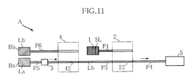
FIG. 11 is a conceptual drawing showing delivery of an eluent in another example of liquid chromatography using the liquid chromatography apparatus shown inFIG. 1 ; -
FIG. 12 is a system configuration diagram showing a state in which a 6-way valve has been rotated in another example of liquid chromatography using the liquid chromatography apparatus shown inFIG. 1 ; -
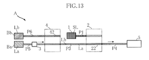
FIG. 13 is a conceptual drawing showing delivery of an eluent in another example of liquid chromatography using the liquid chromatography apparatus shown inFIG. 1 ; -
FIG. 14 is a system configuration diagram showing an example of a liquid chromatography apparatus of the prior art; and, -
FIG. 15 is a graph indicating hysteresis of salt concentration in a column of the liquid chromatography apparatus shown inFIG. 14 . - The following provides a detailed explanation of preferred embodiments of the present invention with reference to the drawings.
-
FIG. 1 shows an example of a liquid chromatography apparatus according to the present invention. A liquid chromatography apparatus A of the present embodiment is provided with asample preparation unit 1, a flow pathdirectional valve 2, afeeder 3, a flow pathdirectional valve 4, ananalysis unit 5 and a controller 6. This liquid chromatography apparatus A carries out liquid chromatography on a specimen S such as blood. - The
sample preparation unit 1 produces a sample on which liquid chromatography is to be carried out by diluting a prescribed amount of the specimen S collected from a blood vessel Ts to a prescribed factor with a diluent Ld collected from a bottle Bd. Thesample preparation unit 1 includes, for example, a needle-shaped nozzle for collecting the specimen S from the blood vessel Ts, a collection tube for collecting the diluent Ld from the bottle Bd, and a stirrer that mixes these. - The flow path
directional valve 2 has, for example, a 6-way valve 21 and aninjection loop 22. The 6-way valve 21 hasports injection loop 22. Theports ports port 21a is connected to a pipe P4, theport 21b is connected to a pipe P3, theports injection loop 22, theport 21d is connected to a pipe P2, and theport 21e is connected to thesample preparation unit 1 through a pipe P1. Theinjection loop 22 is for accumulating a fixed amount of the sample. In the present embodiment, the volume of theinjection loop 22 is made to be, for example, about 3.4 µL. - The
feeder 3 and the flow pathdirectional valve 4 compose an eluent supplier as referred to in the present invention. Thefeeder 3 is for delivering or feeding an eluent La housed in a bottle Ba to the flow pathdirectional valve 4, and is provided in a pipe P5. Thefeeder 3 is composed of aplunger pump 31 and adamper 32. Theplunger pump 31 employs a structure provided with a reciprocating plunger and a check valve, and is equivalent to an example of a fixed displacement pump. Thedamper 32 fulfills the function of alleviating pulsation generated by theplunger pump 31. - The flow path
directional valve 4 has, for example, a 6-way valve 41 and aninjection loop 42. The 6-way valve 41 hasports injection loop 42. Theports ports port 41a is connected to thefeeder 3 through the pipe P5, theport 41b is connected to the flowpath direction valve 2 through the pipe P3, theports injection loop 42, theport 41d is connected to a pipe P7, and theport 41e is connected to a bottle Bb housing an eluent Lb through a pipe P6. In the present embodiment, the eluent Lb has a higher salt concentration than the eluent La. Theinjection loop 42 is for accumulating a fixed amount of the eluent Lb. In the present embodiment, the volume of theinjection loop 42 is made to be, for example, about 142 µL. This is equivalent to an amount delivered for 5 seconds by thefeeder 3. - The
analysis unit 5 is connected to the flow pathdirectional valve 2 through the pipe P4, and is the site where analysis by liquid chromatography is carried out. Theanalysis unit 5 is composed of a pre-filter 51, acolumn 52 and aphotometric unit 53. The pre-filter 51 prevents unwanted substances from entering thecolumn 52. Thecolumn 52 retains a filler for adsorbing the introduced sample. After the sample has been adsorbed onto the filler, when the eluent La is injected into thecolumn 52, the adsorbed sample is desorbed by the eluent La. Moreover, the desorbed sample and the eluent La flow through thecolumn 52 and are discharged as an eluate. Thephotometric unit 53 is composed so as to analyze components of the sample by, for example, measuring absorbance of the eluate flowing from thecolumn 52, and is equivalent to one example of analyzers referred to in the present invention. - The controller 6 respectively drives and controls the
sample preparation unit 1, the flow pathdirectional valve 2, thefeeder 3, the flow pathdirectional valve 4 an theanalysis unit 5, and is composed of, for example, a CPU, a memory and an interface for transmitting and receiving signals. The controller 6 controls processing for carrying out analysis of the sample as described below as well as subsequent analyses. - Next, an explanation is provided of analysis using the liquid chromatography apparatus A with reference to
FIGS. 1 to 10 . - First, the liquid chromatography apparatus A is in an initial analysis state shown in
FIGS. 1 and2. FIG. 2 is schematically represents flow paths of the liquid chromatography apparatus A. In these drawings, a sample SL is prepared by diluting the specimen S with the diluent Ld in thesample preparation unit 1. - Next, as shown in
FIGS. 1 and3 , the sample SL is introduced into theinjection loop 22. This injection is carried out by, for example, an aspiration pump (not shown) arranged downstream from the pipe P2. In addition, at this time, the eluent Lb is introduced into theinjection loop 42. This injection is carried out by, for example, an aspiration pump (not shown) arranged downstream from the pipe P7. As a result of the introduction thereof, a fixed amount of the sample SL is accumulated in theinjection loop 22, and a fixed amount of the eluent Lb is accumulated in theinjection loop 42. - Next, as shown in
FIG. 4 , the 6-way valve 21 of the flow pathdirectional valve 2 is rotated by, for example, 60° in the counter-clockwise direction. As a result, theports injection loop 22, theport 21b is connected to the pipe P4, theport 21c is connected to the port P3, theport 21e is connected to the pipe P2, and theport 21f is connected to the pipe P1. By then driving theplunger pump 31 while in this state, the eluent La is delivered from thefeeder 3 to the flow pathdirectional valve 4. This eluent La moves toward the flow pathdirectional valve 2 as shown inFIG. 5 through theports FIG. 6 , a fixed amount of the sample SL accumulated in theinjection loop 22 with the eluent La is sent to theanalysis unit 5. In theanalysis unit 5, a specific component contained in the sample SL is analyzed by thephotometric unit 53. - In the state in which this analysis is still in progress or has been completed, other components not targeted for analysis other than the specific component targeted for analysis are adhered to the
column 52, for example. These other components are not required for measurement results during analysis or inhibit subsequent analyses. Consequently, the controller 6 carried out control so these other components are eluted and washed out. - Namely, as shown in
FIG. 7 , the 6-way valve 41 of the flow pathdirectional valve 4 is rotated by, for example, 60° in the clockwise direction. As a result, theports injection loop 42, theport 41b is connected to the pipe P5, theport 41c is connected to the pipe P3, theport 41e is connected to the pipe P7, and theport 41f is connected to the pipe P6, resulting in the state shown inFIG. 8 . By driving theplunger pump 31 while in this state, the eluent La is delivered from thefeeder 3 towards the flow pathdirectional valve 4. Whereupon, a fixed amount of the eluent Lb accumulated in theinjection loop 42 is delivered to the pipe P3. This eluent Lb is then disposed between the eluent La that had been in the pipe P3 and the eluent La that has been sent by thefeeder 3. - By continuing to further drive the
plunger pump 31, the entire fixed amount of the eluent Lb is delivered from theinjection loop 42 to the pipe P3 as shown inFIG. 9 . Subsequently, by continuing delivery of the eluent La with thefeeder 3, other components adhered to thecolumn 52 are eluted and washed out by the eluent Lb, and as a result of further adequately filling the system, including thecolumn 52, with the eluent La, thecolumn 52 and the like are made to have a salt concentration suitable for carrying out the next analysis. - Next, an explanation is provided of the action of the liquid chromatography apparatus A and liquid chromatography of the present embodiment.
-
FIG. 10 indicates hysteresis of the salt concentration Ds of thecolumn 52 in processing for the analysis described above and the next analysis. The time T1 is the time at which the leading end of the eluent Lb shown inFIG. 9 has reached thecolumn 52, while the time T2 is the time at which the trailing end of the eluent Lb has reached thecolumn 52. The salt concentration Ds changes abruptly at either of these times T1 and T2, and changes to the salt concentration of the eluent La or Lb, respectively. The following provides a description of the reason for this. - First, the eluents La and Lb are supplied to the flow path
directional valve 4 from separate ports. Consequently, there is no mutual mixing whatsoever in the flow path leading to the flow pathdirectional valve 4. Next, a fixed amount of the eluent Lb is introduced into the eluent La due to rotation of the 6-way valve 41 as shown inFIGS. 7 and8 . In this case, there is only the possibility of the mutual ends of the eluent La and the eluent Lb mixing in an extremely narrow flow path consisting of the pipe P3 and theinjection loop 42. The degree of this mixing is much smaller than the mixing in, for example, the manifold 93 and thefeed pump 94 shown inFIG. 14 . As a result, the eluent Lb is supplied to thecolumn 52 in a state of being surrounded by the eluent La without the occurrence of excessive mixing. Thus, the salt concentration Ds at the time T1 and the time T2 can be made to change abruptly as shown inFIG. 10 . - If it is possible to abruptly change salt concentration in the
column 52 in this manner, it is not necessary to allow a lengthy amount of time to pass until the salt concentration Ds returns to a desired concentration (salt concentration of the eluent La). In addition, in the present embodiment, differing from the use of three types of eluents La, Lb and Lc as in the prior art, only two types of eluents La and Lb are used. Thus, it becomes possible to rapidly return the system, including thecolumn 52, to a state suitable for carrying out the next analysis, thereby making it possible to shorten analysis time of liquid chromatography. In addition, this also serves to reduce consumption of eluent. -
FIGS. 11 to 13 show another embodiment of the liquid chromatography according to the present invention. Furthermore, in these drawings, those elements that are identical or similar to the previously described embodiment are indicated with the same reference symbols as the previous embodiment. In the present embodiment, the controller 6 of the liquid chromatography apparatus A carries out control in a different manner from the previously described embodiment with respect to processing for carrying out the next analysis. - First, processing for carrying out the analysis indicated in
FIGS. 1 to 8 and the next analysis is carried out. Next, the eluent La is delivered by thefeeder 3 from the state shown inFIG. 8 . During this delivery, delivery of the eluent La continues until a portion of a fixed amount of the eluent Lb accumulated in theinjection loop 42 is discharged from theinjection loop 42 as shown inFIG. 11 . More specifically, the plunger of theplunger pump 31, which is a type of fixed displacement pump, is reciprocated a prescribed number of times. Since the amount of the eluent La that is delivered during one reciprocation of this plunger is constant (for example, 28 µL), the amount of the eluent La that is delivered when this plunger is reciprocated a prescribed number of times is also constant. - The 6-
way valve 41 of the flow pathdirectional valve 4 is then rotated by, for example, 60° in the counter-clockwise direction from the state shown inFIG. 11 as shown inFIG. 12 . The eluent La continues to be delivered by thefeeder 3. At this time, as shown inFIG. 13 , the eluent Lb discharged from theinjection loop 42 is surrounded by the eluent La. Subsequently, by further continuing to deliver the eluent La with thefeeder 3, other components adhered to thecolumn 52 are eluted and washed out by the eluent Lb, and as a result of further adequately filling the system, including thecolumn 52, with the eluent La, thecolumn 52 and the like are made to have a salt concentration suitable for carrying out the next analysis. - According to the present embodiment as well, hysteresis of the salt concentration Ds in the
column 52 can be made to resemble the hysteresis shown inFIG. 10 , and the analysis time of liquid chromatography can be shortened. In particular, switching between the trailing end of the eluent Lb and the following eluent La is carried out by rotation of the 6-way valve 41 of the flow pathdirectional valve 4. Consequently, contact time between the trailing end of the eluent Lb and the eluent La can be shortened to a greater degree than the case shown inFIGS. 8 and 9 . As a result, mixing between the trailing end of the eluent Lb and the eluent La can be further inhibited, which is preferable for shortening analysis time. - In addition, since the 6-
way valve 41 is rotated before the entire fixed amount of the eluent Lb accumulated in theinjection loop 42 is discharged after other components not targeted for analysis were able to be eluted, the amount of the eluent Lb sent to thecolumn 52 is even less than the amount in the previously described embodiment. As a result, the amount of time from the time T1 to the time T2 can be further shortened, which is preferable for shortening analysis time. - By using the
plunger pump 31 that is a type of fixed displacement pump, the amount of the eluent Lb discharged from theinjection loop 42 inFIG. 11 can be accurately determined by counting the number of times the plunger reciprocates. This offers the advantage of being able to supply an amount of the eluent Lb that is adequate for eluting and washing out the other components described above while also being the minimum required amount of the eluent Lb from the viewpoint of shortening analysis time. - The liquid chromatography apparatus and liquid chromatography according to the present invention are not limited to the previously described embodiments. The design of specific configurations of the liquid chromatography apparatus and liquid chromatography according to the present invention can be modified in various ways as desired.
- The first and second eluents referred to in the present invention are not limited to those having mutually different salt concentrations, but rather, those having mutually different hydrogen ion concentration indices (pH), for example, may also be used.
Claims (12)
- A liquid chromatography apparatus, comprising:a sample preparation unit for preparing a sample from a specimen;a column for separating components of the sample;an eluent supplier for supplying as a mobile phase two or more types of eluent to the column;a first flow path directional valve capable of introducing a fixed amount of the sample to the column and capable of introducing the eluent to the column;an analyzer for analyzing a test solution composed of the sample components separated by the column and the eluent; anda controller for controlling operation of the sample preparation unit, the eluent supplier, the first flow path directional valve and the analyzer;wherein the eluent supplier supplies two or more types of eluent to the first flow path directional valve in an unmixed state.
- The liquid chromatography apparatus according to claim 1, wherein:the eluent supplier is provided with a second flow path directional valve that is able to supply to the first flow path directional valve first and second eluents mutually supplied to separate ports; andthe controller carries out control so that at least a portion of the fixed amount of the second eluent accumulated in the second flow path directional valve and the first eluent subsequently introduced into the second flow path directional valve from a port different from that of the second eluent are supplied to the column through the first flow path directional valve either during or after analysis of the test solution by supplying the first eluent to the column through the first flow path directional valve.
- The liquid chromatography apparatus according to claim 2, wherein, in supplying the second eluent, in a state in which an injection loop for retaining the fixed amount of the second eluent accumulated in the second flow path directional valve is connected to a pathway leading to the first flow path directional valve, control is carried out that continues to supply the first eluent to the injection loop until all of the fixed amount of the second eluent is discharged from the injection loop.
- The liquid chromatography apparatus according to claim 2, wherein, in supplying the second eluent, in a state in which an injection loop for retaining the fixed amount of the second eluent accumulated in the second flow path directional valve is connected to a pathway leading to the first flow path directional valve, control is carried out that supplies the first eluent in a state in which a remainder of the second eluent is allowed to remain in the injection loop and a pathway different from the injection loop is connected to the pathway leading to the first flow path directional valve, after the first eluent has been supplied to the injection loop until a portion of the fixed amount of the second eluent is discharged from the injection loop.
- The liquid chromatography apparatus according to claim 4, wherein the eluent supplier is provided with a fixed displacement pump that supplies the first eluent to the second flow path directional valve.
- The liquid chromatography apparatus according to claim 1, wherein blood is used as the specimen, with an object being to measure glycohemoglobin.
- A liquid chromatography, comprising:a step of preparing a sample from a specimen;a step of supplying the sample to a column through a first flow path directional valve;a step of supplying as a mobile phase two or more types of eluent to the column through the first flow path directional valve;a step of supplying a test solution composed of components of the sample separated by the column and the eluent to an analyzer; anda step of measuring absorbance of the test solution by the analyzer,wherein the two or more types of eluent are supplied to the first flow path directional valve in an unmixed state.
- The liquid chromatography according to claim 7, further comprising a step of washing the column by supplying to the column at least a portion of a fixed amount of the second eluent accumulated in a second flow path directional valve connected to the first flow path directional valve and the first eluent subsequently introduced into the second flow path directional valve from a port different from that of the second eluent through the first flow path directional valve either during or after the step of measuring absorbance.
- The liquid chromatography according to claim 8, wherein, in the washing step, in a state in which an injection loop for retaining the fixed amount of the second eluent accumulated in the second flow path directional valve is connected to a pathway leading to the first flow path directional valve, the first eluent is continuously supplied to the injection loop until all of the fixed amount of the second eluent is discharged from the injection loop.
- The liquid chromatography according to claim 8, wherein, in the washing step, in a state in which an injection loop for retaining the fixed amount of the second eluent accumulated in the second flow path directional valve is connected to a pathway leading to the first flow path directional valve, the first eluent is supplied in a state in which a remainder of the second eluent is allowed to remain in the injection loop and a pathway different from the injection loop is connected to the pathway leading to the first flow path directional valve, after the first eluent has been supplied to the injection loop until a portion of the fixed amount of the second eluent is discharged from the injection loop.
- The liquid chromatography according to claim 10, wherein supplying of the first eluent to the second flow path directional valve is carried out by using a fixed displacement pump.
- The liquid chromatography according to claim 7, wherein blood is used as the specimen, with an object being to measure glycohemoglobin.
Applications Claiming Priority (2)
| Application Number | Priority Date | Filing Date | Title |
|---|---|---|---|
| JP2008260465A JP2011141120A (en) | 2008-10-07 | 2008-10-07 | Liquid chromatography device and liquid chromatography |
| PCT/JP2009/067369 WO2010041637A1 (en) | 2008-10-07 | 2009-10-06 | Liquid chromatography device and liquid chromatography |
Publications (3)
| Publication Number | Publication Date |
|---|---|
| EP2345896A1 true EP2345896A1 (en) | 2011-07-20 |
| EP2345896A4 EP2345896A4 (en) | 2013-07-03 |
| EP2345896B1 EP2345896B1 (en) | 2017-05-03 |
Family
ID=42100587
Family Applications (1)
| Application Number | Title | Priority Date | Filing Date |
|---|---|---|---|
| EP09819171.1A Active EP2345896B1 (en) | 2008-10-07 | 2009-10-06 | Liquid chromatography device and liquid chromatography method |
Country Status (6)
| Country | Link |
|---|---|
| US (1) | US9310342B2 (en) |
| EP (1) | EP2345896B1 (en) |
| JP (2) | JP2011141120A (en) |
| KR (1) | KR101299644B1 (en) |
| CN (1) | CN102171562B (en) |
| WO (1) | WO2010041637A1 (en) |
Cited By (7)
| Publication number | Priority date | Publication date | Assignee | Title |
|---|---|---|---|---|
| EP2669674A1 (en) * | 2012-05-30 | 2013-12-04 | Arkray, Inc. | Liquid chromatography apparatus, liquid chromatography analysis method, and liquid chromatography analysis program |
| EP2835636A1 (en) * | 2013-08-07 | 2015-02-11 | ARKRAY, Inc. | Liquid chromotography device, liquid chromotography analysis process, and liquid chromotography analysis program |
| WO2016075503A1 (en) * | 2014-11-10 | 2016-05-19 | Agilent Technologies, Inc. | Metering device with defined enabled flow direction |
| EP3023782A4 (en) * | 2013-07-17 | 2017-01-04 | Sekisui Medical Co., Ltd. | Sample analysis device and gradient liquid feed device |
| WO2017070154A2 (en) | 2015-10-20 | 2017-04-27 | Waters Technologies Corporation | Systems, methods and devices for cross-stream injection chromatography |
| FR3105016A1 (en) * | 2019-12-23 | 2021-06-25 | Commissariat A L'energie Atomique Et Aux Energies Alternatives | Devices and methods for mixing liquids back and forth between pump and measuring cell, and physico-chemical analysis of the liquids thus mixed |
| US11204338B2 (en) | 2017-07-05 | 2021-12-21 | Shenzhen Mindray Bio-Medical Electronics Co., Ltd. | Liquid phase analysis device and analysis method for liquid phase analysis device |
Families Citing this family (12)
| Publication number | Priority date | Publication date | Assignee | Title |
|---|---|---|---|---|
| KR101365921B1 (en) * | 2011-09-02 | 2014-02-19 | 주식회사 아모그린텍 | Apparatus for Separating Analytes and Apparatus for Detecting Analytes Using the Same |
| CN103623612A (en) * | 2012-08-29 | 2014-03-12 | 奇复康药物研发(苏州)有限公司 | Liquid adding device |
| CN103969349A (en) * | 2013-01-29 | 2014-08-06 | 深圳普门科技有限公司 | A washing method of inspection equipment and the inspection equipment thereof |
| CN103713055B (en) * | 2013-12-23 | 2015-01-14 | 聚光科技(杭州)股份有限公司 | High-concentration substance detection device and method |
| JP6918555B2 (en) * | 2016-04-13 | 2021-08-11 | 株式会社堀場エステック | How to operate the chromatograph sampler and the chromatograph sampler |
| US10527594B2 (en) * | 2016-04-20 | 2020-01-07 | Arkray, Inc. | Liquid chromatography measurement method, liquid chromatography measurement instrument, and liquid chromatography measurement program storage medium |
| AT519146B1 (en) | 2016-10-05 | 2020-03-15 | Univ Wien Tech | Device for analyzing a solid sample material |
| JP6895819B2 (en) * | 2017-06-26 | 2021-06-30 | アークレイ株式会社 | Liquid chromatography equipment |
| DE112021001274T5 (en) * | 2020-02-24 | 2023-03-02 | Leco Corporation | Split flow modulator for comprehensive two-dimensional chromatography |
| DE102020115737A1 (en) | 2020-06-15 | 2020-07-30 | Agilent Technologies Inc. | Fluid supply devices and fluid component for forming a mobile phase for a sample separator |
| JP2023067746A (en) * | 2021-10-29 | 2023-05-16 | 株式会社島津製作所 | Method for cleaning liquid chromatograph system and liquid chromatograph system |
| WO2024219147A1 (en) * | 2023-04-17 | 2024-10-24 | 株式会社島津製作所 | Analysis system, method for controlling same, and recording medium |
Family Cites Families (26)
| Publication number | Priority date | Publication date | Assignee | Title |
|---|---|---|---|---|
| US3504799A (en) * | 1968-04-02 | 1970-04-07 | Beckman Instruments Inc | Sample injector |
| USRE29454E (en) * | 1972-06-26 | 1977-10-25 | E. I. Du Pont De Nemours And Company | Method for producing a gradient elution |
| US4116046A (en) * | 1977-08-05 | 1978-09-26 | Hoffmann-La Roche Inc. | Liquid chromatography system |
| US4158630A (en) * | 1978-02-24 | 1979-06-19 | Stearns Stanley D | Chromatographic multi-sample valving apparatus |
| US4274967A (en) * | 1978-07-07 | 1981-06-23 | Technicon Instruments Corporation | Chromatographic apparatus and method |
| US4258630A (en) * | 1978-07-25 | 1981-03-31 | Northland Aluminum Products, Inc. | Portable turntable for use in microwave ovens |
| US4478713A (en) * | 1983-09-23 | 1984-10-23 | Pharmuka Laboratoires | Automatic installation for liquid chromatography |
| US4595496A (en) * | 1984-06-29 | 1986-06-17 | Millipore Corporation | Liquid composition control |
| US4728434A (en) * | 1984-07-05 | 1988-03-01 | Magnetopulse Limited | Liquid chromatography |
| US4699718A (en) * | 1986-01-21 | 1987-10-13 | Millipore Corporation | Ion chromatography method and apparatus |
| JPS6336143A (en) * | 1986-07-30 | 1988-02-16 | Tosoh Corp | Method and instrument for measuring stable type saccharogenic hemoglobin |
| US5135718A (en) * | 1987-03-02 | 1992-08-04 | Tosoh Corporation | Apparatus for simultaneously analyzing vanillylmandelic acid, homovanillic acid and creatinine |
| GB2220369B (en) * | 1988-06-10 | 1993-01-27 | Inst Of Child Health | Method for testing body fluids by low pressure liquid chromatography |
| JP2782470B2 (en) * | 1990-07-20 | 1998-07-30 | 株式会社日立製作所 | Glycohemoglobin separation method and separation apparatus and separation column |
| US5468643A (en) | 1991-08-28 | 1995-11-21 | The United States Of America As Represented By The Department Of Health And Human Services | Switching valve system for direct biological sample injection for LC analysis |
| WO1993007168A2 (en) * | 1991-09-30 | 1993-04-15 | Perseptive Biosystems, Inc. | Protein chromatography system |
| JP2669255B2 (en) * | 1992-04-01 | 1997-10-27 | 株式会社日立製作所 | Method for analyzing hemoglobins, analyzer, and column deterioration suppressing liquid used therefor |
| US5520817A (en) * | 1994-10-04 | 1996-05-28 | Biologica Co. | Method of fractionating components in liquid chromatography |
| US7588725B2 (en) * | 2001-04-25 | 2009-09-15 | Biotrove, Inc. | High throughput autosampler |
| JP4603203B2 (en) * | 2001-07-02 | 2010-12-22 | 積水化学工業株式会社 | Liquid chromatograph |
| JP2003107064A (en) * | 2001-09-28 | 2003-04-09 | Shimadzu Corp | High performance liquid chromatograph |
| JP3758585B2 (en) * | 2002-02-27 | 2006-03-22 | 株式会社島津製作所 | Liquid chromatograph system |
| GB0624707D0 (en) * | 2004-05-21 | 2007-01-17 | Waters Investments Ltd | Closed loop flow control of a hplc constant flow pump to enable low-flow operation |
| JP2007240500A (en) | 2006-03-13 | 2007-09-20 | Arkray Inc | Liquid chromatograph |
| US9429579B2 (en) * | 2006-09-22 | 2016-08-30 | Arkray, Inc. | Blood analysis apparatus |
| JP4992401B2 (en) | 2006-12-06 | 2012-08-08 | 株式会社島津製作所 | Autosampler cleaning mechanism |
-
2008
- 2008-10-07 JP JP2008260465A patent/JP2011141120A/en active Pending
-
2009
- 2009-10-06 JP JP2010532911A patent/JP5367716B2/en active Active
- 2009-10-06 WO PCT/JP2009/067369 patent/WO2010041637A1/en not_active Ceased
- 2009-10-06 EP EP09819171.1A patent/EP2345896B1/en active Active
- 2009-10-06 CN CN200980139711.4A patent/CN102171562B/en active Active
- 2009-10-06 US US13/122,602 patent/US9310342B2/en active Active
- 2009-10-06 KR KR1020117009082A patent/KR101299644B1/en active Active
Cited By (12)
| Publication number | Priority date | Publication date | Assignee | Title |
|---|---|---|---|---|
| EP2669674A1 (en) * | 2012-05-30 | 2013-12-04 | Arkray, Inc. | Liquid chromatography apparatus, liquid chromatography analysis method, and liquid chromatography analysis program |
| EP3023782A4 (en) * | 2013-07-17 | 2017-01-04 | Sekisui Medical Co., Ltd. | Sample analysis device and gradient liquid feed device |
| US9970908B2 (en) | 2013-07-17 | 2018-05-15 | Sekisui Medical Co., Ltd. | Gradient liquid feed device for sample analyzer |
| EP2835636A1 (en) * | 2013-08-07 | 2015-02-11 | ARKRAY, Inc. | Liquid chromotography device, liquid chromotography analysis process, and liquid chromotography analysis program |
| WO2016075503A1 (en) * | 2014-11-10 | 2016-05-19 | Agilent Technologies, Inc. | Metering device with defined enabled flow direction |
| US10473632B2 (en) | 2014-11-10 | 2019-11-12 | Agilent Technologies, Inc. | Metering device with defined enabled flow direction |
| WO2017070154A2 (en) | 2015-10-20 | 2017-04-27 | Waters Technologies Corporation | Systems, methods and devices for cross-stream injection chromatography |
| EP3365671A4 (en) * | 2015-10-20 | 2019-07-03 | Waters Technologies Corporation | Systems, methods and devices for cross-stream injection chromatography |
| US11204338B2 (en) | 2017-07-05 | 2021-12-21 | Shenzhen Mindray Bio-Medical Electronics Co., Ltd. | Liquid phase analysis device and analysis method for liquid phase analysis device |
| FR3105016A1 (en) * | 2019-12-23 | 2021-06-25 | Commissariat A L'energie Atomique Et Aux Energies Alternatives | Devices and methods for mixing liquids back and forth between pump and measuring cell, and physico-chemical analysis of the liquids thus mixed |
| WO2021130424A1 (en) * | 2019-12-23 | 2021-07-01 | Commissariat A L'energie Atomique Et Aux Energies Alternatives | Devices and methods for mixing liquids by moving said liquids back and forth between a pump and a measuring cell, and physicochemical analysis of the liquids mixed in this manner |
| US12582951B2 (en) | 2019-12-23 | 2026-03-24 | Commissariat A L'energie Atomique Et Aux Energies Alternatives | Devices and methods for mixing liquids by moving said liquids back and forth between a pump and a measuring cell, and physicochemical analysis of the liquids mixed in this manner |
Also Published As
| Publication number | Publication date |
|---|---|
| JP5367716B2 (en) | 2013-12-11 |
| CN102171562A (en) | 2011-08-31 |
| EP2345896B1 (en) | 2017-05-03 |
| CN102171562B (en) | 2014-07-30 |
| EP2345896A4 (en) | 2013-07-03 |
| WO2010041637A1 (en) | 2010-04-15 |
| JP2011141120A (en) | 2011-07-21 |
| JPWO2010041637A1 (en) | 2012-03-08 |
| KR101299644B1 (en) | 2013-08-23 |
| KR20110073533A (en) | 2011-06-29 |
| US20110186511A1 (en) | 2011-08-04 |
| US9310342B2 (en) | 2016-04-12 |
Similar Documents
| Publication | Publication Date | Title |
|---|---|---|
| EP2345896B1 (en) | Liquid chromatography device and liquid chromatography method | |
| EP3023782B1 (en) | Sample analysis device and gradient liquid feed device | |
| US9694301B2 (en) | Two-dimensional fluid separation with controlled pressure | |
| US10557834B2 (en) | Auto-sampling system for automatically acquiring a sample | |
| US20100107782A1 (en) | Separation Analyzer | |
| JP2015052592A (en) | Liquid chromatography device, liquid chromatography analysis method, and liquid chromatography analysis program | |
| US11913917B2 (en) | Chromatograph and sample injection apparatus | |
| CN103930778A (en) | Valves and Shunting Systems for Multidimensional Liquid Analysis | |
| CN108780064A (en) | Analytical equipment | |
| GB2588635A (en) | Sample injector with fluidic sample mixing | |
| EP2669674A1 (en) | Liquid chromatography apparatus, liquid chromatography analysis method, and liquid chromatography analysis program | |
| EP2343549B1 (en) | Analyzing device and method for controlling same | |
| CN112672799B (en) | Two-dimensional fluid separation with push-pull modulation | |
| US12589329B2 (en) | Fluid separation with sampling unit selectively coupling upstream and downstream of separation unit | |
| CN114113427B (en) | Sample injector | |
| JP5202272B2 (en) | Liquid chromatograph, liquid chromatograph feed pump, and liquid chromatograph cleaning method | |
| JPH0815278A (en) | Sample introduction device | |
| CN222599593U (en) | Intelligent chromatograph with concentration judgment function | |
| JP2023020352A (en) | Method for controlling ion exchange chromatograph and ion exchange chromatograph | |
| CN110741251B (en) | Liquid-phase analysis device and analysis method therefor | |
| EP4555300A1 (en) | A sample delivery system for an analytical instrument |
Legal Events
| Date | Code | Title | Description |
|---|---|---|---|
| PUAI | Public reference made under article 153(3) epc to a published international application that has entered the european phase |
Free format text: ORIGINAL CODE: 0009012 |
|
| 17P | Request for examination filed |
Effective date: 20110426 |
|
| AK | Designated contracting states |
Kind code of ref document: A1 Designated state(s): AT BE BG CH CY CZ DE DK EE ES FI FR GB GR HR HU IE IS IT LI LT LU LV MC MK MT NL NO PL PT RO SE SI SK SM TR |
|
| AX | Request for extension of the european patent |
Extension state: AL BA RS |
|
| DAX | Request for extension of the european patent (deleted) | ||
| A4 | Supplementary search report drawn up and despatched |
Effective date: 20130531 |
|
| RIC1 | Information provided on ipc code assigned before grant |
Ipc: G01N 30/74 20060101ALI20130524BHEP Ipc: G01N 30/88 20060101ALI20130524BHEP Ipc: B01D 15/14 20060101ALI20130524BHEP Ipc: G01N 30/26 20060101AFI20130524BHEP |
|
| RAP1 | Party data changed (applicant data changed or rights of an application transferred) |
Owner name: SEKISUI MEDICAL CO., LTD. Owner name: ARKRAY, INC. |
|
| GRAP | Despatch of communication of intention to grant a patent |
Free format text: ORIGINAL CODE: EPIDOSNIGR1 |
|
| RIC1 | Information provided on ipc code assigned before grant |
Ipc: G01N 30/74 20060101ALN20161007BHEP Ipc: G01N 30/88 20060101ALN20161007BHEP Ipc: B01D 15/14 20060101ALI20161007BHEP Ipc: G01N 30/26 20060101ALI20161007BHEP Ipc: G01N 30/16 20060101AFI20161007BHEP Ipc: G01N 30/20 20060101ALN20161007BHEP |
|
| INTG | Intention to grant announced |
Effective date: 20161103 |
|
| GRAJ | Information related to disapproval of communication of intention to grant by the applicant or resumption of examination proceedings by the epo deleted |
Free format text: ORIGINAL CODE: EPIDOSDIGR1 |
|
| REG | Reference to a national code |
Ref country code: DE Ref legal event code: R079 Ref document number: 602009045913 Country of ref document: DE Free format text: PREVIOUS MAIN CLASS: G01N0030260000 Ipc: G01N0030160000 |
|
| GRAR | Information related to intention to grant a patent recorded |
Free format text: ORIGINAL CODE: EPIDOSNIGR71 |
|
| GRAS | Grant fee paid |
Free format text: ORIGINAL CODE: EPIDOSNIGR3 |
|
| GRAA | (expected) grant |
Free format text: ORIGINAL CODE: 0009210 |
|
| INTC | Intention to grant announced (deleted) | ||
| RIC1 | Information provided on ipc code assigned before grant |
Ipc: G01N 30/20 20060101ALN20170323BHEP Ipc: G01N 30/16 20060101AFI20170323BHEP Ipc: G01N 30/74 20060101ALN20170323BHEP Ipc: B01D 15/14 20060101ALI20170323BHEP Ipc: G01N 30/26 20060101ALI20170323BHEP Ipc: G01N 30/88 20060101ALN20170323BHEP |
|
| AK | Designated contracting states |
Kind code of ref document: B1 Designated state(s): AT BE BG CH CY CZ DE DK EE ES FI FR GB GR HR HU IE IS IT LI LT LU LV MC MK MT NL NO PL PT RO SE SI SK SM TR |
|
| INTG | Intention to grant announced |
Effective date: 20170328 |
|
| REG | Reference to a national code |
Ref country code: GB Ref legal event code: FG4D |
|
| REG | Reference to a national code |
Ref country code: AT Ref legal event code: REF Ref document number: 890541 Country of ref document: AT Kind code of ref document: T Effective date: 20170515 Ref country code: CH Ref legal event code: EP |
|
| REG | Reference to a national code |
Ref country code: IE Ref legal event code: FG4D |
|
| REG | Reference to a national code |
Ref country code: DE Ref legal event code: R096 Ref document number: 602009045913 Country of ref document: DE |
|
| REG | Reference to a national code |
Ref country code: NL Ref legal event code: MP Effective date: 20170503 |
|
| REG | Reference to a national code |
Ref country code: AT Ref legal event code: MK05 Ref document number: 890541 Country of ref document: AT Kind code of ref document: T Effective date: 20170503 |
|
| REG | Reference to a national code |
Ref country code: LT Ref legal event code: MG4D |
|
| REG | Reference to a national code |
Ref country code: FR Ref legal event code: PLFP Year of fee payment: 9 |
|
| PG25 | Lapsed in a contracting state [announced via postgrant information from national office to epo] |
Ref country code: HR Free format text: LAPSE BECAUSE OF FAILURE TO SUBMIT A TRANSLATION OF THE DESCRIPTION OR TO PAY THE FEE WITHIN THE PRESCRIBED TIME-LIMIT Effective date: 20170503 Ref country code: NO Free format text: LAPSE BECAUSE OF FAILURE TO SUBMIT A TRANSLATION OF THE DESCRIPTION OR TO PAY THE FEE WITHIN THE PRESCRIBED TIME-LIMIT Effective date: 20170803 Ref country code: LT Free format text: LAPSE BECAUSE OF FAILURE TO SUBMIT A TRANSLATION OF THE DESCRIPTION OR TO PAY THE FEE WITHIN THE PRESCRIBED TIME-LIMIT Effective date: 20170503 Ref country code: FI Free format text: LAPSE BECAUSE OF FAILURE TO SUBMIT A TRANSLATION OF THE DESCRIPTION OR TO PAY THE FEE WITHIN THE PRESCRIBED TIME-LIMIT Effective date: 20170503 Ref country code: GR Free format text: LAPSE BECAUSE OF FAILURE TO SUBMIT A TRANSLATION OF THE DESCRIPTION OR TO PAY THE FEE WITHIN THE PRESCRIBED TIME-LIMIT Effective date: 20170804 Ref country code: AT Free format text: LAPSE BECAUSE OF FAILURE TO SUBMIT A TRANSLATION OF THE DESCRIPTION OR TO PAY THE FEE WITHIN THE PRESCRIBED TIME-LIMIT Effective date: 20170503 Ref country code: ES Free format text: LAPSE BECAUSE OF FAILURE TO SUBMIT A TRANSLATION OF THE DESCRIPTION OR TO PAY THE FEE WITHIN THE PRESCRIBED TIME-LIMIT Effective date: 20170503 |
|
| PG25 | Lapsed in a contracting state [announced via postgrant information from national office to epo] |
Ref country code: IS Free format text: LAPSE BECAUSE OF FAILURE TO SUBMIT A TRANSLATION OF THE DESCRIPTION OR TO PAY THE FEE WITHIN THE PRESCRIBED TIME-LIMIT Effective date: 20170903 Ref country code: BG Free format text: LAPSE BECAUSE OF FAILURE TO SUBMIT A TRANSLATION OF THE DESCRIPTION OR TO PAY THE FEE WITHIN THE PRESCRIBED TIME-LIMIT Effective date: 20170803 Ref country code: NL Free format text: LAPSE BECAUSE OF FAILURE TO SUBMIT A TRANSLATION OF THE DESCRIPTION OR TO PAY THE FEE WITHIN THE PRESCRIBED TIME-LIMIT Effective date: 20170503 Ref country code: LV Free format text: LAPSE BECAUSE OF FAILURE TO SUBMIT A TRANSLATION OF THE DESCRIPTION OR TO PAY THE FEE WITHIN THE PRESCRIBED TIME-LIMIT Effective date: 20170503 Ref country code: SE Free format text: LAPSE BECAUSE OF FAILURE TO SUBMIT A TRANSLATION OF THE DESCRIPTION OR TO PAY THE FEE WITHIN THE PRESCRIBED TIME-LIMIT Effective date: 20170503 Ref country code: PL Free format text: LAPSE BECAUSE OF FAILURE TO SUBMIT A TRANSLATION OF THE DESCRIPTION OR TO PAY THE FEE WITHIN THE PRESCRIBED TIME-LIMIT Effective date: 20170503 |
|
| PG25 | Lapsed in a contracting state [announced via postgrant information from national office to epo] |
Ref country code: EE Free format text: LAPSE BECAUSE OF FAILURE TO SUBMIT A TRANSLATION OF THE DESCRIPTION OR TO PAY THE FEE WITHIN THE PRESCRIBED TIME-LIMIT Effective date: 20170503 Ref country code: CZ Free format text: LAPSE BECAUSE OF FAILURE TO SUBMIT A TRANSLATION OF THE DESCRIPTION OR TO PAY THE FEE WITHIN THE PRESCRIBED TIME-LIMIT Effective date: 20170503 Ref country code: DK Free format text: LAPSE BECAUSE OF FAILURE TO SUBMIT A TRANSLATION OF THE DESCRIPTION OR TO PAY THE FEE WITHIN THE PRESCRIBED TIME-LIMIT Effective date: 20170503 Ref country code: RO Free format text: LAPSE BECAUSE OF FAILURE TO SUBMIT A TRANSLATION OF THE DESCRIPTION OR TO PAY THE FEE WITHIN THE PRESCRIBED TIME-LIMIT Effective date: 20170503 Ref country code: SK Free format text: LAPSE BECAUSE OF FAILURE TO SUBMIT A TRANSLATION OF THE DESCRIPTION OR TO PAY THE FEE WITHIN THE PRESCRIBED TIME-LIMIT Effective date: 20170503 |
|
| REG | Reference to a national code |
Ref country code: DE Ref legal event code: R097 Ref document number: 602009045913 Country of ref document: DE |
|
| PG25 | Lapsed in a contracting state [announced via postgrant information from national office to epo] |
Ref country code: SM Free format text: LAPSE BECAUSE OF FAILURE TO SUBMIT A TRANSLATION OF THE DESCRIPTION OR TO PAY THE FEE WITHIN THE PRESCRIBED TIME-LIMIT Effective date: 20170503 |
|
| PLBE | No opposition filed within time limit |
Free format text: ORIGINAL CODE: 0009261 |
|
| STAA | Information on the status of an ep patent application or granted ep patent |
Free format text: STATUS: NO OPPOSITION FILED WITHIN TIME LIMIT |
|
| 26N | No opposition filed |
Effective date: 20180206 |
|
| PG25 | Lapsed in a contracting state [announced via postgrant information from national office to epo] |
Ref country code: MC Free format text: LAPSE BECAUSE OF FAILURE TO SUBMIT A TRANSLATION OF THE DESCRIPTION OR TO PAY THE FEE WITHIN THE PRESCRIBED TIME-LIMIT Effective date: 20170503 Ref country code: SI Free format text: LAPSE BECAUSE OF FAILURE TO SUBMIT A TRANSLATION OF THE DESCRIPTION OR TO PAY THE FEE WITHIN THE PRESCRIBED TIME-LIMIT Effective date: 20170503 |
|
| REG | Reference to a national code |
Ref country code: CH Ref legal event code: PL |
|
| REG | Reference to a national code |
Ref country code: IE Ref legal event code: MM4A |
|
| PG25 | Lapsed in a contracting state [announced via postgrant information from national office to epo] |
Ref country code: LU Free format text: LAPSE BECAUSE OF NON-PAYMENT OF DUE FEES Effective date: 20171006 Ref country code: CH Free format text: LAPSE BECAUSE OF NON-PAYMENT OF DUE FEES Effective date: 20171031 Ref country code: LI Free format text: LAPSE BECAUSE OF NON-PAYMENT OF DUE FEES Effective date: 20171031 |
|
| REG | Reference to a national code |
Ref country code: BE Ref legal event code: MM Effective date: 20171031 |
|
| PG25 | Lapsed in a contracting state [announced via postgrant information from national office to epo] |
Ref country code: BE Free format text: LAPSE BECAUSE OF NON-PAYMENT OF DUE FEES Effective date: 20171031 |
|
| PG25 | Lapsed in a contracting state [announced via postgrant information from national office to epo] |
Ref country code: MT Free format text: LAPSE BECAUSE OF NON-PAYMENT OF DUE FEES Effective date: 20171006 |
|
| REG | Reference to a national code |
Ref country code: FR Ref legal event code: PLFP Year of fee payment: 10 |
|
| PG25 | Lapsed in a contracting state [announced via postgrant information from national office to epo] |
Ref country code: IE Free format text: LAPSE BECAUSE OF NON-PAYMENT OF DUE FEES Effective date: 20171006 |
|
| PG25 | Lapsed in a contracting state [announced via postgrant information from national office to epo] |
Ref country code: HU Free format text: LAPSE BECAUSE OF FAILURE TO SUBMIT A TRANSLATION OF THE DESCRIPTION OR TO PAY THE FEE WITHIN THE PRESCRIBED TIME-LIMIT; INVALID AB INITIO Effective date: 20091006 |
|
| PG25 | Lapsed in a contracting state [announced via postgrant information from national office to epo] |
Ref country code: CY Free format text: LAPSE BECAUSE OF NON-PAYMENT OF DUE FEES Effective date: 20170503 |
|
| PG25 | Lapsed in a contracting state [announced via postgrant information from national office to epo] |
Ref country code: MK Free format text: LAPSE BECAUSE OF FAILURE TO SUBMIT A TRANSLATION OF THE DESCRIPTION OR TO PAY THE FEE WITHIN THE PRESCRIBED TIME-LIMIT Effective date: 20170503 |
|
| PG25 | Lapsed in a contracting state [announced via postgrant information from national office to epo] |
Ref country code: TR Free format text: LAPSE BECAUSE OF FAILURE TO SUBMIT A TRANSLATION OF THE DESCRIPTION OR TO PAY THE FEE WITHIN THE PRESCRIBED TIME-LIMIT Effective date: 20170503 |
|
| PG25 | Lapsed in a contracting state [announced via postgrant information from national office to epo] |
Ref country code: PT Free format text: LAPSE BECAUSE OF FAILURE TO SUBMIT A TRANSLATION OF THE DESCRIPTION OR TO PAY THE FEE WITHIN THE PRESCRIBED TIME-LIMIT Effective date: 20170503 |
|
| REG | Reference to a national code |
Ref country code: DE Ref legal event code: R082 Ref document number: 602009045913 Country of ref document: DE |
|
| P01 | Opt-out of the competence of the unified patent court (upc) registered |
Effective date: 20230612 |
|
| PGFP | Annual fee paid to national office [announced via postgrant information from national office to epo] |
Ref country code: DE Payment date: 20251021 Year of fee payment: 17 |
|
| PGFP | Annual fee paid to national office [announced via postgrant information from national office to epo] |
Ref country code: GB Payment date: 20251022 Year of fee payment: 17 |
|
| PGFP | Annual fee paid to national office [announced via postgrant information from national office to epo] |
Ref country code: IT Payment date: 20251024 Year of fee payment: 17 |
|
| PGFP | Annual fee paid to national office [announced via postgrant information from national office to epo] |
Ref country code: FR Payment date: 20251029 Year of fee payment: 17 |