EP2345579A2 - Compact electromechanical actuator - Google Patents
Compact electromechanical actuator Download PDFInfo
- Publication number
- EP2345579A2 EP2345579A2 EP20110250040 EP11250040A EP2345579A2 EP 2345579 A2 EP2345579 A2 EP 2345579A2 EP 20110250040 EP20110250040 EP 20110250040 EP 11250040 A EP11250040 A EP 11250040A EP 2345579 A2 EP2345579 A2 EP 2345579A2
- Authority
- EP
- European Patent Office
- Prior art keywords
- motor
- set forth
- actuator
- component
- shows
- Prior art date
- Legal status (The legal status is an assumption and is not a legal conclusion. Google has not performed a legal analysis and makes no representation as to the accuracy of the status listed.)
- Granted
Links
Images




Classifications
-
- B—PERFORMING OPERATIONS; TRANSPORTING
- B64—AIRCRAFT; AVIATION; COSMONAUTICS
- B64C—AEROPLANES; HELICOPTERS
- B64C13/00—Control systems or transmitting systems for actuating flying-control surfaces, lift-increasing flaps, air brakes, or spoilers
- B64C13/24—Transmitting means
- B64C13/38—Transmitting means with power amplification
- B64C13/50—Transmitting means with power amplification using electrical energy
-
- H—ELECTRICITY
- H02—GENERATION; CONVERSION OR DISTRIBUTION OF ELECTRIC POWER
- H02K—DYNAMO-ELECTRIC MACHINES
- H02K21/00—Synchronous motors having permanent magnets; Synchronous generators having permanent magnets
- H02K21/12—Synchronous motors having permanent magnets; Synchronous generators having permanent magnets with stationary armatures and rotating magnets
- H02K21/14—Synchronous motors having permanent magnets; Synchronous generators having permanent magnets with stationary armatures and rotating magnets with magnets rotating within the armatures
- H02K21/145—Synchronous motors having permanent magnets; Synchronous generators having permanent magnets with stationary armatures and rotating magnets with magnets rotating within the armatures having an annular armature coil
-
- H—ELECTRICITY
- H02—GENERATION; CONVERSION OR DISTRIBUTION OF ELECTRIC POWER
- H02K—DYNAMO-ELECTRIC MACHINES
- H02K21/00—Synchronous motors having permanent magnets; Synchronous generators having permanent magnets
- H02K21/12—Synchronous motors having permanent magnets; Synchronous generators having permanent magnets with stationary armatures and rotating magnets
- H02K21/22—Synchronous motors having permanent magnets; Synchronous generators having permanent magnets with stationary armatures and rotating magnets with magnets rotating around the armatures, e.g. flywheel magnetos
- H02K21/227—Synchronous motors having permanent magnets; Synchronous generators having permanent magnets with stationary armatures and rotating magnets with magnets rotating around the armatures, e.g. flywheel magnetos having an annular armature coil
-
- H—ELECTRICITY
- H02—GENERATION; CONVERSION OR DISTRIBUTION OF ELECTRIC POWER
- H02K—DYNAMO-ELECTRIC MACHINES
- H02K5/00—Casings; Enclosures; Supports
- H02K5/04—Casings or enclosures characterised by the shape, form or construction thereof
- H02K5/18—Casings or enclosures characterised by the shape, form or construction thereof with ribs or fins for improving heat transfer
-
- H—ELECTRICITY
- H02—GENERATION; CONVERSION OR DISTRIBUTION OF ELECTRIC POWER
- H02K—DYNAMO-ELECTRIC MACHINES
- H02K5/00—Casings; Enclosures; Supports
- H02K5/04—Casings or enclosures characterised by the shape, form or construction thereof
- H02K5/22—Auxiliary parts of casings not covered by groups H02K5/06-H02K5/20, e.g. shaped to form connection boxes or terminal boxes
- H02K5/225—Terminal boxes or connection arrangements
-
- H—ELECTRICITY
- H02—GENERATION; CONVERSION OR DISTRIBUTION OF ELECTRIC POWER
- H02K—DYNAMO-ELECTRIC MACHINES
- H02K7/00—Arrangements for handling mechanical energy structurally associated with dynamo-electric machines, e.g. structural association with mechanical driving motors or auxiliary dynamo-electric machines
- H02K7/10—Structural association with clutches, brakes, gears, pulleys or mechanical starters
- H02K7/116—Structural association with clutches, brakes, gears, pulleys or mechanical starters with gears
-
- Y—GENERAL TAGGING OF NEW TECHNOLOGICAL DEVELOPMENTS; GENERAL TAGGING OF CROSS-SECTIONAL TECHNOLOGIES SPANNING OVER SEVERAL SECTIONS OF THE IPC; TECHNICAL SUBJECTS COVERED BY FORMER USPC CROSS-REFERENCE ART COLLECTIONS [XRACs] AND DIGESTS
- Y02—TECHNOLOGIES OR APPLICATIONS FOR MITIGATION OR ADAPTATION AGAINST CLIMATE CHANGE
- Y02T—CLIMATE CHANGE MITIGATION TECHNOLOGIES RELATED TO TRANSPORTATION
- Y02T50/00—Aeronautics or air transport
- Y02T50/40—Weight reduction
Definitions
- This application relates to the use of a transverse flux motor in an electromechanical actuator for aircraft application.
- Aircraft are typically provided with a number of linear actuators to position various components.
- stabilizers, flaps, slats, spoilers, ailerons, elevators and rudders must be precisely positioned, and have their positions changed during flight.
- electromechanical actuators having a standard electric motor (parallel flux motor) driving a linear actuator through a rotary to linear conversion are utilized. Due to the types of motors that have historically been utilized, a step-down gear box has also been included as the electric motors have typically provided higher speeds than are needed at the actual aircraft components.
- Transverse flux motors are known. However, they have not been utilized in conjunction with the above-referenced application.
- An electromechanical actuator for controlling the position of an aircraft component has a linear actuator.
- a transverse flux motor drives the linear actuator to move in a linear direction and control the position of the component.
- Figure 1 shows an aircraft 20 which incorporates several components such as elevator 22, rudders 24, horizontal stabilizers 26, flaps 28, slats 30, spoilers 132, and ailerons 134.
- components such as elevator 22, rudders 24, horizontal stabilizers 26, flaps 28, slats 30, spoilers 132, and ailerons 134.
- Each of these components are precisely positioned during flight dynamics to ensure proper flight by controlling aerodynamic properties.
- electromechanical actuators are utilized to move the components.
- FIG 2 shows a prior art electromechanical actuator 40.
- a typical standard parallel flux motor 42 is utilized. Such motors typically deliver relatively high speed to a gear box 44.
- the gear box 44 includes a gear 39 driving idler gear 43 to in turn drive gear 41.
- These three required gears result in a relatively large and heavy gear box 44.
- the output of the gear 41 drives a threaded shaft 45.
- a ball screw 46 has an anti-rotation mechanism, which translates rotation of the threaded member 45 into linear movement of an output member 48.
- This mechanical connection is as known.
- the linear member 48 is connected to a clevice 50 which in turn moves the component, here an elevator 22.
- FIG 3A shows an inventive embodiment 59 wherein a transverse flux motor 62 is utilized.
- a transverse flux motor can provide a relatively lower speed because high input frequency is converted electromagnetically into low speed of the shaft. This is an inherent and most important feature of a transverse flux motor.
- the transverse flux motor 62 drives a first gear 60 which in turn drives a gear 61 to drive the threaded shaft 45.
- the remainder of the connection may be as known in the prior art.
- Figure 3B shows an alternative arrangement 155 wherein the transverse flux motor 162 drives the shaft 45 directly.
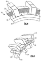
- Figure 4 shows a first arrangement 30 for a single sided machine, and shows a stator having cylindrical coil 32 associated with pole pieces 34.
- a rotor 38 is provided with permanent magnets 36.
- Figure 5 shows a double-sided machine wherein there is an additional coil 132 and pole pieces 134 on an opposed side of the rotor 38.
- transverse flux machines can be utilized in any of the embodiments as set forth below.
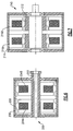
- Figure 6 shows a machine embodiment 200 which is single phase, and which is provided with two redundant channels 204A and 204B, such that it is fault tolerant.
- the embodiment of Figure 6 has an internal stator 202 surrounded by the rotor 206 and its permanent magnets 208.
- the internal stator application is particularly useful for this aircraft application in that it results in a relatively smaller volume envelope, and lighter weight.
- Figure 7 shows another embodiment 210, wherein the rotor 212 is internal to the stator, and its redundant channels 216A and 216B.
- a three-phase transverse flux motor 205 can be provided that has an internal stator 209 and an external rotor 212.
- the external stator 209 provides three phases through stator coils 211.
- Figure 9 shows an alternative machine 207 wherein the rotor 215 is internal, and the stator 216 and its three phases 218 are external.
- Figure 10 shows a three-phase machine, again having redundant circuits for fault tolerance.
- the stator 302 is internal, and includes pole pieces 304AB, 305A/B, and 306A/B, and an external rotor 310.
- an external stator can also be used in a similar embodiment.
- a control circuit 300 is shown in Figure 11 .
- the electromechanical actuator 301 receives three phases of power 302 from any one of the embodiments illustrated in this application.
- Angular feedback extends from a motor position sensor 303 and an actuator position sensor 301 back to the control.
- a speed estimator 1001 also provides feedback to an actuator command generator 1002 and an actuator position regulator 300.
- An actuator position command 310 extends into these blocks.
- actuator motor torque and reactive power regulators 1003 also provide feedback to control the power supplied to the three phases 302 via PWM inverter 1005.
- the actuator controller has three distinctive blocks: a command generator 1002, an actuator position regulator 300, and a motor torque and reactive power regulator 1003.
- the command generator generates optimal time-varying velocity and position references in response to the actuator input position command.
- the actuator position regulator is responsive to the input references by closing actuator velocity in position routes.
- the output of the position regulator is a motor torque-producing current reference Iq*.
- the motor torque and reactive power regulator utilize a synchronous rotating reference frame controls with cross-coupling in voltage feedforward terms. Motor torque is controlled in response to the Iq* current reference by closing Iq current loop utilizing a PI controller 1006.
- Reactive power reference Q* is set to zero to achieve unity power factor operation. Closed loop reactive power control generates a negative Id* current reference at the PI controller output.
- the direct and quadrature feedback voltage and currents are derived at the output of the abc-to-dq transformation blocks which are synchronized with the motor rotor position. Idq and Vdq variables, and are also used to compute reactive power feedback signal Q, block 1007.
- Figure 12 shows the actuator 301 having electrical connection 320, and a heat sink 322.
- the present invention provides a much lighter weight electromechanical actuator. Moreover, given the elimination of the gear trains, a motor may be provided with a redundant set of paths, such that it is more fault resistant, and yet still results in a lighter weight electromechanical actuator than has been provided in the prior art.
- transverse flux machine provides benefits (high power density, compact construction, simple winding, low winding losses, high efficiency, modular construction, fault tolerance) when compared to a standard flux machine.
Landscapes
- Engineering & Computer Science (AREA)
- Power Engineering (AREA)
- Physics & Mathematics (AREA)
- Thermal Sciences (AREA)
- Automation & Control Theory (AREA)
- Aviation & Aerospace Engineering (AREA)
- Connection Of Motors, Electrical Generators, Mechanical Devices, And The Like (AREA)
- Linear Motors (AREA)
Abstract
Description
- This application relates to the use of a transverse flux motor in an electromechanical actuator for aircraft application.
- Aircraft are typically provided with a number of linear actuators to position various components. As an example, stabilizers, flaps, slats, spoilers, ailerons, elevators and rudders must be precisely positioned, and have their positions changed during flight.
- In the prior art, electromechanical actuators having a standard electric motor (parallel flux motor) driving a linear actuator through a rotary to linear conversion are utilized. Due to the types of motors that have historically been utilized, a step-down gear box has also been included as the electric motors have typically provided higher speeds than are needed at the actual aircraft components.
- Due to the above restrictions, the resulting electromechanical actuators have been relatively high weight.
- Transverse flux motors are known. However, they have not been utilized in conjunction with the above-referenced application.
- An electromechanical actuator for controlling the position of an aircraft component has a linear actuator. A transverse flux motor drives the linear actuator to move in a linear direction and control the position of the component.
- These and other features of the present invention can be best understood from the following specification and drawings, the following of which is a brief description.
-
-
Figure 1 shows an aircraft. -
Figure 2 shows a prior art electromechanical actuator. -
Figure 3A shows a first arrangement of an inventive actuator. -
Figure 3B shows an alternative arrangement -
Figure 4 shows a first type of transverse flux machine. -
Figure 5 shows an alternative transverse flux machine. -
Figure 6 shows another option of a transverse flux machine. -
Figure 7 shows another option of a transverse flux machine. -
Figure 8 shows yet another option. -
Figure 9 shows yet another option. -
Figure 10 shows yet another option. -
Figure 11 shows a control circuit for any one of the embodiments as described above. -
Figure 12 shows a perspective view of an electromechanical actuator according to this application. -
Figure 1 shows anaircraft 20 which incorporates several components such aselevator 22,rudders 24,horizontal stabilizers 26,flaps 28,slats 30,spoilers 132, andailerons 134. Each of these components are precisely positioned during flight dynamics to ensure proper flight by controlling aerodynamic properties. Typically, electromechanical actuators are utilized to move the components. -
Figure 2 shows a prior artelectromechanical actuator 40. A typical standardparallel flux motor 42 is utilized. Such motors typically deliver relatively high speed to agear box 44. Thus, as shown, thegear box 44 includes agear 39 drivingidler gear 43 to inturn drive gear 41. These three required gears result in a relatively large andheavy gear box 44. The output of thegear 41 drives a threadedshaft 45. Aball screw 46 has an anti-rotation mechanism, which translates rotation of the threadedmember 45 into linear movement of anoutput member 48. This mechanical connection is as known. Thelinear member 48 is connected to aclevice 50 which in turn moves the component, here anelevator 22. -
Figure 3A shows aninventive embodiment 59 wherein atransverse flux motor 62 is utilized. A transverse flux motor can provide a relatively lower speed because high input frequency is converted electromagnetically into low speed of the shaft. This is an inherent and most important feature of a transverse flux motor. Thetransverse flux motor 62 drives afirst gear 60 which in turn drives a gear 61 to drive the threadedshaft 45. The remainder of the connection may be as known in the prior art. -
Figure 3B shows analternative arrangement 155 wherein thetransverse flux motor 162 drives theshaft 45 directly. - As can be appreciated from
Figures 3A and 3B , a reduction in weight is achieved with these arrangements compared to the prior art ofFigure 2 . -
Figure 4 shows afirst arrangement 30 for a single sided machine, and shows a stator havingcylindrical coil 32 associated withpole pieces 34. Arotor 38 is provided withpermanent magnets 36. -
Figure 5 shows a double-sided machine wherein there is anadditional coil 132 andpole pieces 134 on an opposed side of therotor 38. - These basic arrangements of transverse flux machines can be utilized in any of the embodiments as set forth below.
-
Figure 6 shows amachine embodiment 200 which is single phase, and which is provided with tworedundant channels Figure 6 has aninternal stator 202 surrounded by therotor 206 and itspermanent magnets 208. The internal stator application is particularly useful for this aircraft application in that it results in a relatively smaller volume envelope, and lighter weight. -
Figure 7 shows anotherembodiment 210, wherein therotor 212 is internal to the stator, and itsredundant channels - As shown in
Figure 8 , a three-phasetransverse flux motor 205 can be provided that has aninternal stator 209 and anexternal rotor 212. Theexternal stator 209 provides three phases throughstator coils 211. -
Figure 9 shows analternative machine 207 wherein therotor 215 is internal, and thestator 216 and its threephases 218 are external. -
Figure 10 shows a three-phase machine, again having redundant circuits for fault tolerance. InFigure 10 machine 300, thestator 302 is internal, and includes pole pieces 304AB, 305A/B, and 306A/B, and anexternal rotor 310. Of course, an external stator can also be used in a similar embodiment. - A
control circuit 300 is shown inFigure 11 . Theelectromechanical actuator 301 receives three phases ofpower 302 from any one of the embodiments illustrated in this application. Angular feedback extends from amotor position sensor 303 and anactuator position sensor 301 back to the control. Aspeed estimator 1001 also provides feedback to anactuator command generator 1002 and anactuator position regulator 300. Anactuator position command 310 extends into these blocks. Further, actuator motor torque andreactive power regulators 1003 also provide feedback to control the power supplied to the threephases 302 viaPWM inverter 1005. - Essentially, the actuator controller has three distinctive blocks: a
command generator 1002, anactuator position regulator 300, and a motor torque andreactive power regulator 1003. The command generator generates optimal time-varying velocity and position references in response to the actuator input position command. The actuator position regulator is responsive to the input references by closing actuator velocity in position routes. The output of the position regulator is a motor torque-producing current reference Iq*. The motor torque and reactive power regulator utilize a synchronous rotating reference frame controls with cross-coupling in voltage feedforward terms. Motor torque is controlled in response to the Iq* current reference by closing Iq current loop utilizing aPI controller 1006. Reactive power reference Q* is set to zero to achieve unity power factor operation. Closed loop reactive power control generates a negative Id* current reference at the PI controller output. - The direct and quadrature feedback voltage and currents are derived at the output of the abc-to-dq transformation blocks which are synchronized with the motor rotor position. Idq and Vdq variables, and are also used to compute reactive power feedback signal Q,
block 1007. -
Figure 12 shows theactuator 301 havingelectrical connection 320, and aheat sink 322. - The present invention provides a much lighter weight electromechanical actuator. Moreover, given the elimination of the gear trains, a motor may be provided with a redundant set of paths, such that it is more fault resistant, and yet still results in a lighter weight electromechanical actuator than has been provided in the prior art.
- The use of the transverse flux machine provides benefits (high power density, compact construction, simple winding, low winding losses, high efficiency, modular construction, fault tolerance) when compared to a standard flux machine.
- Although embodiments of this invention have been disclosed, a worker of ordinary skill in this art would recognize that certain modifications would come within the scope of this invention. For that reason, the following claims should be studied to determine the true scope and content of this invention.
Claims (10)
- An electromechanical actuator for controlling the position of an aircraft component, comprising:a linear actuator to be driven to position a component; anda transverse flux motor driving said linear actuator to move in a linear direction and control the position of the component.
- The system as set forth in claim 1, wherein a ball screw connection connects said motor to said linear actuator.
- The system as set forth in claim 2, wherein said motor drives a first gear which engages and drives an output gear to in turn drive a rotating threaded member to move said ball screw, and move said linear actuator.
- The system as set forth in claim 2, wherein said motor directly drives a threaded member to move said ball screw, and drive said linear actuator.
- The system as set forth in claim 1, 2, 3 or 4, wherein said motor carries a redundant set of coils.
- The system as set forth in claim 5, wherein said motor is a three-phase motor.
- The system as set forth in any of claims 1 to 6, wherein said motor includes an internal stator having at least one coil.
- The system as set forth in any of claims 1 to 6, wherein said motor has an external stator having at least one coil.
- An aircraft component and drive comprising:an electromechanical actuator as claimed in any preceding claim arranged to control the position of an aircraft component.
- The aircraft component as recited in claim 9, wherein said component controls aerodynamic properties.
Applications Claiming Priority (1)
| Application Number | Priority Date | Filing Date | Title |
|---|---|---|---|
| US12/687,152 US8390160B2 (en) | 2010-01-14 | 2010-01-14 | Compact electromechanical actuator |
Publications (3)
| Publication Number | Publication Date |
|---|---|
| EP2345579A2 true EP2345579A2 (en) | 2011-07-20 |
| EP2345579A3 EP2345579A3 (en) | 2014-10-08 |
| EP2345579B1 EP2345579B1 (en) | 2016-05-25 |
Family
ID=43877035
Family Applications (1)
| Application Number | Title | Priority Date | Filing Date |
|---|---|---|---|
| EP11250040.0A Active EP2345579B1 (en) | 2010-01-14 | 2011-01-14 | Compact electromechanical actuator |
Country Status (6)
| Country | Link |
|---|---|
| US (1) | US8390160B2 (en) |
| EP (1) | EP2345579B1 (en) |
| KR (1) | KR101325852B1 (en) |
| CN (1) | CN102130536B (en) |
| BR (1) | BRPI1100695B1 (en) |
| CA (1) | CA2728235C (en) |
Cited By (4)
| Publication number | Priority date | Publication date | Assignee | Title |
|---|---|---|---|---|
| RU2607490C2 (en) * | 2015-06-18 | 2017-01-10 | Открытое акционерное общество Московский научно-производственный комплекс "Авионика" имени О.В. Успенского (ОАО МНПК "Авионика") | Control system actuator |
| EP3451514A1 (en) * | 2017-08-28 | 2019-03-06 | Hamilton Sundstrand Corporation | Actuator assembly |
| WO2022053177A1 (en) * | 2020-09-09 | 2022-03-17 | Eaton Intelligent Power Limited | Control surface actuation synchronization system |
| US11952107B2 (en) | 2020-09-09 | 2024-04-09 | Eaton Intelligent Power Limited | Control surface actuation synchronization system |
Families Citing this family (31)
| Publication number | Priority date | Publication date | Assignee | Title |
|---|---|---|---|---|
| JP2012508549A (en) | 2008-11-03 | 2012-04-05 | モーター エクセレンス, エルエルシー | Stator concept for lateral and / or commutated flux systems |
| WO2011115632A1 (en) | 2010-03-15 | 2011-09-22 | Motor Excellence Llc | Transverse and/or commutated flux systems configured to provide reduced flux leakage, hysteresis loss reduction, and phase matching |
| CN102959832B (en) * | 2010-03-15 | 2016-11-16 | 电扭矩机器股份有限公司 | Transverse and/or commutated flux systems with phase offset |
| WO2011115633A1 (en) | 2010-03-15 | 2011-09-22 | Motor Excellence Llc | Transverse and/or commutated flux system for electric bicycles |
| WO2012067896A2 (en) | 2010-11-17 | 2012-05-24 | Motor Excellence, Llc | Transverse and/or commutated flux systems having laminated and powdered metal portions |
| WO2012067895A2 (en) | 2010-11-17 | 2012-05-24 | Motor Excellence, Llc | Transverse and/or commutated flux system coil concepts |
| EP2641316B1 (en) | 2010-11-17 | 2019-02-13 | Motor Excellence, LLC | Transverse and/or commutated flux systems having segmented stator laminations |
| US8904891B2 (en) * | 2011-07-19 | 2014-12-09 | Hamilton Sundstrand Corporation | Wiper for translating ram |
| GB2498208B (en) | 2012-01-06 | 2017-12-20 | Ge Aviat Systems Ltd | Electrical actuator incorporating a free play mechanism to eliminate force fighting |
| CN104953780A (en) | 2012-08-03 | 2015-09-30 | 埃塞克科技有限公司 | Modular rotatable transverse flux electrical machine |
| CA2827650A1 (en) | 2012-09-24 | 2014-03-24 | Eocycle Technologies Inc. | Transverse flux electrical machine stator and assembly thereof |
| CA2829812A1 (en) | 2012-10-17 | 2014-04-17 | Eocycle Technologies Inc. | Transverse flux electrical machine rotor |
| CN102931760B (en) * | 2012-11-15 | 2015-03-25 | 北京自动化控制设备研究所 | Compact electric servo mechanism for linear displacement |
| JP6158022B2 (en) * | 2013-09-30 | 2017-07-05 | 株式会社東芝 | Rotating electric machine and vehicle |
| US10689097B2 (en) | 2014-05-16 | 2020-06-23 | Bombardier Inc. | Actuators and methods for aircraft flight control surfaces |
| US9771164B2 (en) | 2014-10-27 | 2017-09-26 | Hamilton Sundstrand Corporation | Electric system architecture included in a more-electric engine (MEE) system |
| CN105337447A (en) * | 2015-11-27 | 2016-02-17 | 湖北三江航天红峰控制有限公司 | Pancake electric steering engine |
| US10693358B2 (en) | 2017-02-03 | 2020-06-23 | Hamilton Sundstrand Corporation | Reciprocating electromagnetic actuator with flux-balanced armature and stationary cores |
| JP7053381B2 (en) * | 2018-06-13 | 2022-04-12 | Ntn株式会社 | Rotor unit, electric motor and electric actuator |
| US10663041B2 (en) | 2018-08-14 | 2020-05-26 | Hamilton Sunstrand Corporation | Jam-tolerant electric linear actuator |
| CN109592016A (en) * | 2018-11-06 | 2019-04-09 | 珠海隆华直升机科技有限公司 | The linear driving device of helicopter and helicopter |
| CN109592015A (en) * | 2018-11-06 | 2019-04-09 | 珠海隆华直升机科技有限公司 | The linear steering engine of helicopter and helicopter |
| CN109768741B (en) * | 2019-03-26 | 2021-01-05 | 北京航空航天大学 | Drive controller and control method for permanent magnet fault-tolerant motor of airborne electric actuator |
| US11836018B2 (en) | 2020-03-19 | 2023-12-05 | Canrig Robotic Technologies As | Robotic system including an internal cooling system |
| US11719044B2 (en) | 2020-03-19 | 2023-08-08 | Canrig Robotic Technologies As | Robotic system including an electrical clamping system |
| DE102021103936B4 (en) | 2021-02-19 | 2022-12-15 | Liebherr-Aerospace Lindenberg Gmbh | Actuator for an aircraft control surface |
| WO2023034522A1 (en) * | 2021-09-01 | 2023-03-09 | Tolomatic, Inc. | Tip dresser system with integrated transverse flux motor |
| EP4206490B1 (en) * | 2022-01-03 | 2026-03-18 | Goodrich Actuation Systems SAS | A trim horizontal stabiliser actuator comprising an electromechanical linear actuator |
| US12509950B2 (en) | 2022-09-30 | 2025-12-30 | Nabors Drilling Technologies Usa, Inc. | Dual speed linear actuator assembly |
| DE102024119481A1 (en) * | 2024-07-09 | 2026-01-15 | Liebherr-Aerospace Lindenberg Gmbh | Electromechanical actuator for operating a flight control application |
| WO2026044103A1 (en) * | 2024-08-23 | 2026-02-26 | Milwaukee Electric Tool Corporation | Power tools including transverse flux motors |
Family Cites Families (22)
| Publication number | Priority date | Publication date | Assignee | Title |
|---|---|---|---|---|
| CN2315706Y (en) * | 1998-01-22 | 1999-04-21 | 张锦民 | Motor push rod |
| US6169930B1 (en) | 1998-04-17 | 2001-01-02 | International Business Machines Corporation | Method and apparatus for preventing cold temperature induced damage in a disk drive |
| US6145395A (en) * | 1999-01-19 | 2000-11-14 | E-Drive Design, Inc. | Side load compensated linear actuator |
| DE19961201B4 (en) | 1999-12-18 | 2004-08-12 | Frankl & Kirchner GmbH & Co KG Fabrik für Elektromotoren u. elektrische Apparate | Drive for a sewing machine, in particular an industrial sewing machine |
| DE10014226A1 (en) * | 2000-03-22 | 2001-09-27 | Bosch Gmbh Robert | Electromechanical wheel brake has transversal flux motor with annular stimulation winding enclosing axis, yokes distributed peripherally on stimulation winding, matching movable poles |
| US20040026158A1 (en) | 2000-03-27 | 2004-02-12 | Peter Rieth | Vehicle system and axle guide module for a vehicle steering system |
| EP1290774B1 (en) | 2000-05-05 | 2005-05-04 | Robert Bosch Gmbh | Unipolar transverse flux machine |
| JP2002046039A (en) | 2000-08-01 | 2002-02-12 | Smc Corp | Electric actuator |
| JP3488686B2 (en) | 2000-12-05 | 2004-01-19 | Smc株式会社 | Actuator |
| US20030089826A1 (en) | 2001-11-13 | 2003-05-15 | Barba Valentin G. | Flight lock actuator with dual energy sources |
| TW509219U (en) * | 2001-12-31 | 2002-11-01 | Avision Inc | Detecting device for positions of document placement |
| US7230361B2 (en) | 2003-01-31 | 2007-06-12 | Light Engineering, Inc. | Efficient high-speed electric device using low-loss materials |
| US20040251759A1 (en) | 2003-06-12 | 2004-12-16 | Hirzel Andrew D. | Radial airgap, transverse flux motor |
| EP2506404A3 (en) * | 2004-02-06 | 2013-07-31 | L&P Property Management Company | In-line actuator apparatus and method |
| JP4496031B2 (en) | 2004-07-29 | 2010-07-07 | 株式会社東海理化電機製作所 | Steering lock device |
| JP4465524B2 (en) | 2004-08-30 | 2010-05-19 | Smc株式会社 | Electric actuator |
| CN2781087Y (en) * | 2004-11-05 | 2006-05-17 | 周俊 | Error correction execution mechanism |
| CN100390039C (en) * | 2005-03-31 | 2008-05-28 | 王秋楠 | Elevator or lift device for relieving trouble |
| JP4351188B2 (en) | 2005-06-21 | 2009-10-28 | 株式会社日立製作所 | Actuator device and assembly method thereof |
| US20080203223A1 (en) | 2006-06-22 | 2008-08-28 | Cyrot Luc P | Aircraft stabilizer actuator |
| GB0618572D0 (en) * | 2006-09-21 | 2006-11-01 | Goodrich Actuation Systems Ltd | Actuator |
| JP2008141920A (en) | 2006-12-05 | 2008-06-19 | Nsk Ltd | Electric actuator for automobile |
-
2010
- 2010-01-14 US US12/687,152 patent/US8390160B2/en active Active
- 2010-12-31 KR KR1020100139727A patent/KR101325852B1/en active Active
-
2011
- 2011-01-12 BR BRPI1100695-1A patent/BRPI1100695B1/en active IP Right Grant
- 2011-01-13 CA CA2728235A patent/CA2728235C/en active Active
- 2011-01-14 CN CN201110007421.3A patent/CN102130536B/en active Active
- 2011-01-14 EP EP11250040.0A patent/EP2345579B1/en active Active
Non-Patent Citations (1)
| Title |
|---|
| None |
Cited By (7)
| Publication number | Priority date | Publication date | Assignee | Title |
|---|---|---|---|---|
| RU2607490C2 (en) * | 2015-06-18 | 2017-01-10 | Открытое акционерное общество Московский научно-производственный комплекс "Авионика" имени О.В. Успенского (ОАО МНПК "Авионика") | Control system actuator |
| EP3451514A1 (en) * | 2017-08-28 | 2019-03-06 | Hamilton Sundstrand Corporation | Actuator assembly |
| US11001372B2 (en) | 2017-08-28 | 2021-05-11 | Hamilton Sundstrand Corporation | Actuator assembly |
| US11724795B2 (en) | 2017-08-28 | 2023-08-15 | Hamilton Sundstrand Corporation | Actuator assembly |
| WO2022053177A1 (en) * | 2020-09-09 | 2022-03-17 | Eaton Intelligent Power Limited | Control surface actuation synchronization system |
| US11939042B2 (en) | 2020-09-09 | 2024-03-26 | Eaton Intelligent Power Limited | Control surface actuation synchronization system |
| US11952107B2 (en) | 2020-09-09 | 2024-04-09 | Eaton Intelligent Power Limited | Control surface actuation synchronization system |
Also Published As
| Publication number | Publication date |
|---|---|
| CN102130536B (en) | 2015-04-01 |
| BRPI1100695B1 (en) | 2021-03-02 |
| US8390160B2 (en) | 2013-03-05 |
| KR101325852B1 (en) | 2013-11-05 |
| CN102130536A (en) | 2011-07-20 |
| US20110169357A1 (en) | 2011-07-14 |
| CA2728235C (en) | 2014-09-09 |
| EP2345579B1 (en) | 2016-05-25 |
| BRPI1100695A2 (en) | 2012-07-17 |
| CA2728235A1 (en) | 2011-07-14 |
| KR20110083498A (en) | 2011-07-20 |
| EP2345579A3 (en) | 2014-10-08 |
Similar Documents
| Publication | Publication Date | Title |
|---|---|---|
| EP2345579B1 (en) | Compact electromechanical actuator | |
| US6541877B2 (en) | Wind power generation system | |
| Morimoto et al. | Wide-speed operation of interior permanent magnet synchronous motors with high-performance current regulator | |
| US6325331B1 (en) | Trim actuator | |
| EP3375981A1 (en) | Variable speed ac bus powered tail cone boundary layer ingestion thruster | |
| CN102957243B (en) | rotating electrical machine | |
| US7538501B2 (en) | Power system comprising several synchronous machines synchronously self-controlled by a converter and control method for such a system | |
| CN106416051B (en) | motor drive | |
| US20110290125A1 (en) | Servo press apparatus driven by multiple motors | |
| JP2010268579A (en) | Permanent magnet synchronous electric motor system and magnetic field control method therefor | |
| KR20110083497A (en) | Lowest Temperature Control for Electromechanical Actuators | |
| US12237799B2 (en) | Electric motor control | |
| Hussain et al. | Pseudo direct drive electrical machines for flight control surface actuation | |
| US10770994B2 (en) | Variable torque electric motor assembly | |
| Li et al. | Study on PMSM power consumption of dual-variable electro-hydraulic actuator with displacement-pressure regulation pump | |
| WO2023275096A1 (en) | Electric machine with an electromagnetic bearing | |
| EP3477845B1 (en) | Variable torque electric motor assembly | |
| TWI870306B (en) | Rotating motor with multiple stators sharing a rotor and operating method thereof | |
| EP1745339B1 (en) | Method of controlling a high-friction electro-mechanical servo-mechanism to minimize the power needed to hold a loaded output member | |
| JP2025016282A (en) | driver | |
| KR20190034580A (en) | Electric Actuators for Vehicle Transmission Systems | |
| US20230361699A1 (en) | Pump actuating device, and associated pumping system, aircraft and fuel supply method | |
| EP3477832A1 (en) | Variable torque electric motor assembly | |
| CN119995434A (en) | A dual-redundancy matrix motor system and fault-tolerant control method | |
| Botan et al. | Optimal control of a servo drive system with a PMSM |
Legal Events
| Date | Code | Title | Description |
|---|---|---|---|
| PUAI | Public reference made under article 153(3) epc to a published international application that has entered the european phase |
Free format text: ORIGINAL CODE: 0009012 |
|
| AK | Designated contracting states |
Kind code of ref document: A2 Designated state(s): AL AT BE BG CH CY CZ DE DK EE ES FI FR GB GR HR HU IE IS IT LI LT LU LV MC MK MT NL NO PL PT RO RS SE SI SK SM TR |
|
| AX | Request for extension of the european patent |
Extension state: BA ME |
|
| PUAL | Search report despatched |
Free format text: ORIGINAL CODE: 0009013 |
|
| AK | Designated contracting states |
Kind code of ref document: A3 Designated state(s): AL AT BE BG CH CY CZ DE DK EE ES FI FR GB GR HR HU IE IS IT LI LT LU LV MC MK MT NL NO PL PT RO RS SE SI SK SM TR |
|
| AX | Request for extension of the european patent |
Extension state: BA ME |
|
| RIC1 | Information provided on ipc code assigned before grant |
Ipc: H02K 7/116 20060101ALI20140901BHEP Ipc: B64C 13/50 20060101AFI20140901BHEP Ipc: F16H 25/22 20060101ALN20140901BHEP |
|
| 17P | Request for examination filed |
Effective date: 20150402 |
|
| RBV | Designated contracting states (corrected) |
Designated state(s): AL AT BE BG CH CY CZ DE DK EE ES FI FR GB GR HR HU IE IS IT LI LT LU LV MC MK MT NL NO PL PT RO RS SE SI SK SM TR |
|
| GRAP | Despatch of communication of intention to grant a patent |
Free format text: ORIGINAL CODE: EPIDOSNIGR1 |
|
| RIC1 | Information provided on ipc code assigned before grant |
Ipc: F16H 25/22 20060101ALN20151216BHEP Ipc: H02K 5/22 20060101ALI20151216BHEP Ipc: H02K 21/22 20060101ALI20151216BHEP Ipc: H02K 7/116 20060101ALI20151216BHEP Ipc: B64C 13/50 20060101AFI20151216BHEP Ipc: H02K 5/18 20060101ALI20151216BHEP Ipc: H02K 21/14 20060101ALI20151216BHEP Ipc: H02K 21/18 20060101ALI20151216BHEP |
|
| INTG | Intention to grant announced |
Effective date: 20160114 |
|
| RIC1 | Information provided on ipc code assigned before grant |
Ipc: B64C 13/50 20060101AFI20160104BHEP Ipc: H02K 5/18 20060101ALI20160104BHEP Ipc: H02K 5/22 20060101ALI20160104BHEP Ipc: H02K 21/18 20060101ALI20160104BHEP Ipc: H02K 21/14 20060101ALI20160104BHEP Ipc: F16H 25/22 20060101ALN20160104BHEP Ipc: H02K 21/22 20060101ALI20160104BHEP Ipc: H02K 7/116 20060101ALI20160104BHEP |
|
| GRAS | Grant fee paid |
Free format text: ORIGINAL CODE: EPIDOSNIGR3 |
|
| GRAA | (expected) grant |
Free format text: ORIGINAL CODE: 0009210 |
|
| AK | Designated contracting states |
Kind code of ref document: B1 Designated state(s): AL AT BE BG CH CY CZ DE DK EE ES FI FR GB GR HR HU IE IS IT LI LT LU LV MC MK MT NL NO PL PT RO RS SE SI SK SM TR |
|
| REG | Reference to a national code |
Ref country code: GB Ref legal event code: FG4D |
|
| REG | Reference to a national code |
Ref country code: CH Ref legal event code: EP |
|
| REG | Reference to a national code |
Ref country code: IE Ref legal event code: FG4D Ref country code: AT Ref legal event code: REF Ref document number: 802068 Country of ref document: AT Kind code of ref document: T Effective date: 20160615 |
|
| REG | Reference to a national code |
Ref country code: DE Ref legal event code: R096 Ref document number: 602011026862 Country of ref document: DE |
|
| REG | Reference to a national code |
Ref country code: LT Ref legal event code: MG4D |
|
| REG | Reference to a national code |
Ref country code: NL Ref legal event code: MP Effective date: 20160525 |
|
| PG25 | Lapsed in a contracting state [announced via postgrant information from national office to epo] |
Ref country code: NO Free format text: LAPSE BECAUSE OF FAILURE TO SUBMIT A TRANSLATION OF THE DESCRIPTION OR TO PAY THE FEE WITHIN THE PRESCRIBED TIME-LIMIT Effective date: 20160825 Ref country code: NL Free format text: LAPSE BECAUSE OF FAILURE TO SUBMIT A TRANSLATION OF THE DESCRIPTION OR TO PAY THE FEE WITHIN THE PRESCRIBED TIME-LIMIT Effective date: 20160525 Ref country code: LT Free format text: LAPSE BECAUSE OF FAILURE TO SUBMIT A TRANSLATION OF THE DESCRIPTION OR TO PAY THE FEE WITHIN THE PRESCRIBED TIME-LIMIT Effective date: 20160525 Ref country code: FI Free format text: LAPSE BECAUSE OF FAILURE TO SUBMIT A TRANSLATION OF THE DESCRIPTION OR TO PAY THE FEE WITHIN THE PRESCRIBED TIME-LIMIT Effective date: 20160525 |
|
| REG | Reference to a national code |
Ref country code: AT Ref legal event code: MK05 Ref document number: 802068 Country of ref document: AT Kind code of ref document: T Effective date: 20160525 |
|
| PG25 | Lapsed in a contracting state [announced via postgrant information from national office to epo] |
Ref country code: GR Free format text: LAPSE BECAUSE OF FAILURE TO SUBMIT A TRANSLATION OF THE DESCRIPTION OR TO PAY THE FEE WITHIN THE PRESCRIBED TIME-LIMIT Effective date: 20160826 Ref country code: PT Free format text: LAPSE BECAUSE OF FAILURE TO SUBMIT A TRANSLATION OF THE DESCRIPTION OR TO PAY THE FEE WITHIN THE PRESCRIBED TIME-LIMIT Effective date: 20160926 Ref country code: HR Free format text: LAPSE BECAUSE OF FAILURE TO SUBMIT A TRANSLATION OF THE DESCRIPTION OR TO PAY THE FEE WITHIN THE PRESCRIBED TIME-LIMIT Effective date: 20160525 Ref country code: LV Free format text: LAPSE BECAUSE OF FAILURE TO SUBMIT A TRANSLATION OF THE DESCRIPTION OR TO PAY THE FEE WITHIN THE PRESCRIBED TIME-LIMIT Effective date: 20160525 Ref country code: SE Free format text: LAPSE BECAUSE OF FAILURE TO SUBMIT A TRANSLATION OF THE DESCRIPTION OR TO PAY THE FEE WITHIN THE PRESCRIBED TIME-LIMIT Effective date: 20160525 Ref country code: RS Free format text: LAPSE BECAUSE OF FAILURE TO SUBMIT A TRANSLATION OF THE DESCRIPTION OR TO PAY THE FEE WITHIN THE PRESCRIBED TIME-LIMIT Effective date: 20160525 Ref country code: ES Free format text: LAPSE BECAUSE OF FAILURE TO SUBMIT A TRANSLATION OF THE DESCRIPTION OR TO PAY THE FEE WITHIN THE PRESCRIBED TIME-LIMIT Effective date: 20160525 |
|
| REG | Reference to a national code |
Ref country code: FR Ref legal event code: PLFP Year of fee payment: 7 |
|
| PG25 | Lapsed in a contracting state [announced via postgrant information from national office to epo] |
Ref country code: SK Free format text: LAPSE BECAUSE OF FAILURE TO SUBMIT A TRANSLATION OF THE DESCRIPTION OR TO PAY THE FEE WITHIN THE PRESCRIBED TIME-LIMIT Effective date: 20160525 Ref country code: RO Free format text: LAPSE BECAUSE OF FAILURE TO SUBMIT A TRANSLATION OF THE DESCRIPTION OR TO PAY THE FEE WITHIN THE PRESCRIBED TIME-LIMIT Effective date: 20160525 Ref country code: CZ Free format text: LAPSE BECAUSE OF FAILURE TO SUBMIT A TRANSLATION OF THE DESCRIPTION OR TO PAY THE FEE WITHIN THE PRESCRIBED TIME-LIMIT Effective date: 20160525 Ref country code: EE Free format text: LAPSE BECAUSE OF FAILURE TO SUBMIT A TRANSLATION OF THE DESCRIPTION OR TO PAY THE FEE WITHIN THE PRESCRIBED TIME-LIMIT Effective date: 20160525 Ref country code: DK Free format text: LAPSE BECAUSE OF FAILURE TO SUBMIT A TRANSLATION OF THE DESCRIPTION OR TO PAY THE FEE WITHIN THE PRESCRIBED TIME-LIMIT Effective date: 20160525 |
|
| PG25 | Lapsed in a contracting state [announced via postgrant information from national office to epo] |
Ref country code: AT Free format text: LAPSE BECAUSE OF FAILURE TO SUBMIT A TRANSLATION OF THE DESCRIPTION OR TO PAY THE FEE WITHIN THE PRESCRIBED TIME-LIMIT Effective date: 20160525 Ref country code: PL Free format text: LAPSE BECAUSE OF FAILURE TO SUBMIT A TRANSLATION OF THE DESCRIPTION OR TO PAY THE FEE WITHIN THE PRESCRIBED TIME-LIMIT Effective date: 20160525 Ref country code: BE Free format text: LAPSE BECAUSE OF FAILURE TO SUBMIT A TRANSLATION OF THE DESCRIPTION OR TO PAY THE FEE WITHIN THE PRESCRIBED TIME-LIMIT Effective date: 20160525 Ref country code: SM Free format text: LAPSE BECAUSE OF FAILURE TO SUBMIT A TRANSLATION OF THE DESCRIPTION OR TO PAY THE FEE WITHIN THE PRESCRIBED TIME-LIMIT Effective date: 20160525 |
|
| REG | Reference to a national code |
Ref country code: DE Ref legal event code: R097 Ref document number: 602011026862 Country of ref document: DE |
|
| PLBE | No opposition filed within time limit |
Free format text: ORIGINAL CODE: 0009261 |
|
| STAA | Information on the status of an ep patent application or granted ep patent |
Free format text: STATUS: NO OPPOSITION FILED WITHIN TIME LIMIT |
|
| 26N | No opposition filed |
Effective date: 20170228 |
|
| PG25 | Lapsed in a contracting state [announced via postgrant information from national office to epo] |
Ref country code: SI Free format text: LAPSE BECAUSE OF FAILURE TO SUBMIT A TRANSLATION OF THE DESCRIPTION OR TO PAY THE FEE WITHIN THE PRESCRIBED TIME-LIMIT Effective date: 20160525 |
|
| REG | Reference to a national code |
Ref country code: CH Ref legal event code: PL |
|
| PG25 | Lapsed in a contracting state [announced via postgrant information from national office to epo] |
Ref country code: MC Free format text: LAPSE BECAUSE OF FAILURE TO SUBMIT A TRANSLATION OF THE DESCRIPTION OR TO PAY THE FEE WITHIN THE PRESCRIBED TIME-LIMIT Effective date: 20160525 |
|
| PG25 | Lapsed in a contracting state [announced via postgrant information from national office to epo] |
Ref country code: CH Free format text: LAPSE BECAUSE OF NON-PAYMENT OF DUE FEES Effective date: 20170131 Ref country code: LI Free format text: LAPSE BECAUSE OF NON-PAYMENT OF DUE FEES Effective date: 20170131 |
|
| REG | Reference to a national code |
Ref country code: IE Ref legal event code: MM4A |
|
| PG25 | Lapsed in a contracting state [announced via postgrant information from national office to epo] |
Ref country code: LU Free format text: LAPSE BECAUSE OF NON-PAYMENT OF DUE FEES Effective date: 20170114 |
|
| REG | Reference to a national code |
Ref country code: FR Ref legal event code: PLFP Year of fee payment: 8 |
|
| PG25 | Lapsed in a contracting state [announced via postgrant information from national office to epo] |
Ref country code: IE Free format text: LAPSE BECAUSE OF NON-PAYMENT OF DUE FEES Effective date: 20170114 |
|
| PG25 | Lapsed in a contracting state [announced via postgrant information from national office to epo] |
Ref country code: MT Free format text: LAPSE BECAUSE OF NON-PAYMENT OF DUE FEES Effective date: 20170114 |
|
| PG25 | Lapsed in a contracting state [announced via postgrant information from national office to epo] |
Ref country code: AL Free format text: LAPSE BECAUSE OF FAILURE TO SUBMIT A TRANSLATION OF THE DESCRIPTION OR TO PAY THE FEE WITHIN THE PRESCRIBED TIME-LIMIT Effective date: 20160525 |
|
| PG25 | Lapsed in a contracting state [announced via postgrant information from national office to epo] |
Ref country code: HU Free format text: LAPSE BECAUSE OF FAILURE TO SUBMIT A TRANSLATION OF THE DESCRIPTION OR TO PAY THE FEE WITHIN THE PRESCRIBED TIME-LIMIT; INVALID AB INITIO Effective date: 20110114 |
|
| PG25 | Lapsed in a contracting state [announced via postgrant information from national office to epo] |
Ref country code: BG Free format text: LAPSE BECAUSE OF FAILURE TO SUBMIT A TRANSLATION OF THE DESCRIPTION OR TO PAY THE FEE WITHIN THE PRESCRIBED TIME-LIMIT Effective date: 20160525 |
|
| PG25 | Lapsed in a contracting state [announced via postgrant information from national office to epo] |
Ref country code: CY Free format text: LAPSE BECAUSE OF NON-PAYMENT OF DUE FEES Effective date: 20160525 |
|
| PG25 | Lapsed in a contracting state [announced via postgrant information from national office to epo] |
Ref country code: MK Free format text: LAPSE BECAUSE OF FAILURE TO SUBMIT A TRANSLATION OF THE DESCRIPTION OR TO PAY THE FEE WITHIN THE PRESCRIBED TIME-LIMIT Effective date: 20160525 |
|
| PG25 | Lapsed in a contracting state [announced via postgrant information from national office to epo] |
Ref country code: TR Free format text: LAPSE BECAUSE OF FAILURE TO SUBMIT A TRANSLATION OF THE DESCRIPTION OR TO PAY THE FEE WITHIN THE PRESCRIBED TIME-LIMIT Effective date: 20160525 |
|
| PG25 | Lapsed in a contracting state [announced via postgrant information from national office to epo] |
Ref country code: IS Free format text: LAPSE BECAUSE OF FAILURE TO SUBMIT A TRANSLATION OF THE DESCRIPTION OR TO PAY THE FEE WITHIN THE PRESCRIBED TIME-LIMIT Effective date: 20160925 |
|
| REG | Reference to a national code |
Ref country code: DE Ref legal event code: R082 Ref document number: 602011026862 Country of ref document: DE |
|
| P01 | Opt-out of the competence of the unified patent court (upc) registered |
Effective date: 20230522 |
|
| PGFP | Annual fee paid to national office [announced via postgrant information from national office to epo] |
Ref country code: GB Payment date: 20260127 Year of fee payment: 16 |
|
| PGFP | Annual fee paid to national office [announced via postgrant information from national office to epo] |
Ref country code: DE Payment date: 20260114 Year of fee payment: 16 |
|
| PGFP | Annual fee paid to national office [announced via postgrant information from national office to epo] |
Ref country code: IT Payment date: 20260108 Year of fee payment: 16 |
|
| PGFP | Annual fee paid to national office [announced via postgrant information from national office to epo] |
Ref country code: FR Payment date: 20260128 Year of fee payment: 16 |