EP2345561A1 - Occupant restraint device for vehicles - Google Patents
Occupant restraint device for vehicles Download PDFInfo
- Publication number
- EP2345561A1 EP2345561A1 EP09825958A EP09825958A EP2345561A1 EP 2345561 A1 EP2345561 A1 EP 2345561A1 EP 09825958 A EP09825958 A EP 09825958A EP 09825958 A EP09825958 A EP 09825958A EP 2345561 A1 EP2345561 A1 EP 2345561A1
- Authority
- EP
- European Patent Office
- Prior art keywords
- belt
- seat
- occupant
- vehicle
- air
- Prior art date
- Legal status (The legal status is an assumption and is not a legal conclusion. Google has not performed a legal analysis and makes no representation as to the accuracy of the status listed.)
- Granted
Links
Images


Classifications
-
- B—PERFORMING OPERATIONS; TRANSPORTING
- B60—VEHICLES IN GENERAL
- B60N—SEATS SPECIALLY ADAPTED FOR VEHICLES; VEHICLE PASSENGER ACCOMMODATION NOT OTHERWISE PROVIDED FOR
- B60N2/00—Seats specially adapted for vehicles; Arrangement or mounting of seats in vehicles
- B60N2/68—Seat frames
- B60N2/688—Particular seat belt attachment and guiding
-
- B—PERFORMING OPERATIONS; TRANSPORTING
- B60—VEHICLES IN GENERAL
- B60R—VEHICLES, VEHICLE FITTINGS, OR VEHICLE PARTS, NOT OTHERWISE PROVIDED FOR
- B60R21/00—Arrangements or fittings on vehicles for protecting or preventing injuries to occupants or pedestrians in case of accidents or other traffic risks
- B60R21/02—Occupant safety arrangements or fittings, e.g. crash pads
- B60R21/16—Inflatable occupant restraints or confinements designed to inflate upon impact or impending impact, e.g. air bags
- B60R21/18—Inflatable occupant restraints or confinements designed to inflate upon impact or impending impact, e.g. air bags the inflatable member formed as a belt or harness or combined with a belt or harness arrangement
-
- B—PERFORMING OPERATIONS; TRANSPORTING
- B60—VEHICLES IN GENERAL
- B60R—VEHICLES, VEHICLE FITTINGS, OR VEHICLE PARTS, NOT OTHERWISE PROVIDED FOR
- B60R22/00—Safety belts or body harnesses in vehicles
- B60R22/18—Anchoring devices
- B60R22/26—Anchoring devices secured to the seat
-
- B—PERFORMING OPERATIONS; TRANSPORTING
- B60—VEHICLES IN GENERAL
- B60R—VEHICLES, VEHICLE FITTINGS, OR VEHICLE PARTS, NOT OTHERWISE PROVIDED FOR
- B60R22/00—Safety belts or body harnesses in vehicles
- B60R22/02—Semi-passive restraint systems, e.g. systems applied or removed automatically but not both ; Manual restraint systems
- B60R2022/027—Four-point seat belt systems, e.g. with the two upper points connected together
-
- B—PERFORMING OPERATIONS; TRANSPORTING
- B60—VEHICLES IN GENERAL
- B60R—VEHICLES, VEHICLE FITTINGS, OR VEHICLE PARTS, NOT OTHERWISE PROVIDED FOR
- B60R22/00—Safety belts or body harnesses in vehicles
- B60R22/18—Anchoring devices
- B60R2022/1818—Belt guides
Definitions
- a configuration is known in which an air belt passes through a shoulder portion of a seat back, wherein an air belt guide that is erected at a seat width direction outer side with respect to the expanded air belt is provided at the shoulder portion of the seat back.
- JP-A Japanese Patent Application Laid-Open
- an air belt device refer to the specification of United States Patent Application Publication No. 2003/0168837 and Japanese National Phase Publication No. 2001-521462 .
- An occupant restraining device for a vehicle comprises: a seat belt comprising an upper body restraining portion for restraining an upper body of an occupant, the seat belt being pulled out from a retractor when applied to the occupant; and a belt insertion portion that is formed by indenting a portion, in a seat width direction, of an upper end of a seat back, and into which an upper side portion of the upper body restraining portion of the seat belt is made to enter.
- the belt insertion portion is formed by indenting a portion, in the seat width direction, of the upper end of the seat back. Further, movement, in the seat width direction, of the seat belt is restricted by recess walls positioned at both sides in the seat width direction, at the portion that is made to enter into the belt insertion portion. That is to say, the position of the seat belt is regulated by the belt insertion portion.
- An occupant restraining device for a vehicle comprises: a seat belt comprising an upper body restraining portion for restraining an upper body of an occupant, the seat belt being pulled out from a retractor when applied to the occupant; an expanding belt portion which is provided at a portion of the seat belt that includes the upper body restraining portion and a portion at an upper side of the upper body restraining portion, and which is expanded and deployed by gas supply; and a belt insertion portion which includes a recess formed by indenting a portion, in a seat width direction, of an upper end of a seat back, and in which a lower portion, in a vehicle up-down direction, of the expanding belt portion is made to enter into the recess when the expanding belt portion is deployed.
- the upper body of the occupant is restrained by the upper body restraining portions of the left and right pair of the seat belts.
- the expanding belt portions of the left and right pair of the seat belts are expanded and deployed, they intervene with each other so that repelling forces act in the seat width direction.
- the left and right expanding belt portions are respectively supported by the recess walls at the vehicle width direction outer sides of the belt insertion portions into which the left and right expanding belt portions have been made to enter (the recess walls generate a supporting reaction force for the expanding belt portions), and therefore, the occupant is well protected by the left and right expanding belt portions.
- a configuration may be provided, wherein a planar surface maintenance structure for maintaining a planar surface shape of a contact surface contacting with a bottom surface of the belt insertion portion when the expanding belt portion is deployed is provided at the expanding belt portion.
- the contact surface, of the expanding belt in the deployment process or deployment state, that contacts with the bottom surface of the belt insertion portion is maintained in a planar surface (flat) shape by the planar surface maintenance structure.
- the occupant restraining device for a vehicle has the excellent effect of being able to regulate the position of the seat belt without occupying vehicle cabin space.
- the seat belt 12 extends in a vehicle up-down direction at one end side in the width direction of the vehicle seat 11, and a tongue plate 20 is provided at a substantially intermediate portion in the up-down direction thereof.
- the tongue plate 20 is configured so as to be capable of coupling and release of the coupling with respect to a buckle 22 disposed at an opposite side in the width direction of the vehicle seat 11.
- a configuration is provided in which, by coupling the tongue plate 20 with the buckle 22, a shoulder belt portion 12A serving as an upper body restraining portion extending from a shoulder portion of the seat back 16 to the tongue plate 20 spans diagonally across an upper body of an occupant.
- the seat belt 12 is configured so as to restrain the upper body of the seated occupant P at the shoulder belt portion 12A as shown in Fig. 2 , and so that a lap belt portion (illustration of which is omitted from the drawings) extending from the tongue plate 20 to the anchor restrains a hip portion of the seated occupant P.
- the air belt device 10 is configured as an air belt device having a three-point-type seat belt device as a base thereof. Further, in the air belt device 10, the retractor 14 is disposed to the rear of the seat back 16 as described above.
- the seat belt 12 which is put in an application state by the seated occupant P at the vehicle seat 11, is provided with a configuration in which a portion directly above the shoulder belt portion 12A is wound across a shoulder portion 16A (a belt insertion portion 32 which will be described later) of the seat back 16.
- a configuration is provided in which a shoulder anchor or the like that guides the seat belt 12 is not provided between the retractor 14 and the shoulder portion 16A of the seat back 16.
- the air belt 24 is configured so that, due to receiving gas supply from the unillustrated inflator arranged at the retractor 14 side or the anchor side and the air bag 30 being expanded, the entire air belt 24 is expanded and deployed as shown by the imaginary lines in Fig. 2 and in Fig. 3B and Fig. 4 .
- a portion of the seat belt 12 other than the air belt 24 is joined with the cover 26 by stitching or the like.
- the inflator is configured such that, for example, in a case where (the inevitability of) a frontal collision of the vehicle is detected or predicted, the inflator is activated by an unillustrated ECU and supplies gas to the air bag 30.
- the air belt device 10 comprises a belt insertion portion 32 for regulating a position of the seat belt 12 (air belt 24).
- the belt insertion portion 32 is formed as a recess by indenting a portion, in the seat width direction, of the shoulder portion 16A of the seat back 16 across the entire length thereof in the vehicle front-rear direction, so as to open upward in the vehicle up-down direction.
- a setting region of the air belt 24 of the seat belt 12 is slidably inserted into the belt insertion portion 32.
- the air belt 24 is configured so as to be made to enter into the belt insertion portion 32 so as to be slidable in the longitudinal direction thereof, at least in the application state of the seat belt 12 by the seated occupant P at the vehicle seat 11.
- the belt insertion portion 32 has a width that is equal to or greater than a width of the air belt 24. Further, the width and the depth of the belt insertion portion 32 is determined such that a portion (cross section) of the air belt 24 that is expanded directly above the shoulder portion 16A of the seat back 16 is inserted into the belt insertion portion 32 by only about 1/3 of the up-down direction dimension thereof.
- the retractor 14 is disposed at the same position or lower in the vehicle up-down direction with respect to the shoulder portion 16A (bottom of the belt insertion portion 32) of the seat back 16.
- the air belt 24 can be inserted into the belt insertion portion 32 (wound across the bottom of the belt insertion portion 32) without using a shoulder anchor or the like that guides the seat belt 12 (air belt 24) as described above.
- the seated occupant P at the vehicle seat 11 couples the tongue plate 20 with the buckle 22 while pulling out the seat belt 12 from the retractor 14.
- the shoulder belt portion 12A restrains the upper body of the seated occupant P
- the unillustrated lap belt portion restrains the hip portion of the seated occupant P.
- the air belt 24 is entered into the belt insertion portion 32 formed at the seat back 16.
- movement of the air belt 24 in the seat width direction is restricted by a pair of recess walls 32A of the belt insertion portion 32 that face each other in the seat width direction. That is to say, the position of the expanded and deployed air belt 24 with respect to the vehicle seat 11 (occupant) is regulated.
- movement of the air belt 24 toward the seat width direction outer sides is restricted by the recess walls 32A at the seat width direction outer sides.
- the portion across which the seat belt 12 is wound is a lower position with respect to the comparative example.
- the shoulder belt portion 12A is disposed at a position at which it is less likely to interfere with the neck portion for an occupant whose relative sitting height is low, as shown by solid lines in Fig. 5 .
- movement of the seat belt 12 toward the side of the neck portion of the seated occupant P is restricted by the recess wall 32A at the vehicle width direction inner side of the belt insertion portion 32.
- a contribution is made to properly applying the shoulder belt portion 12A to the seated occupant P having a small build whose sitting height is low, such as a child or the like.
- an air belt device 40 serving as an occupant restraining device for a vehicle according to a second exemplary embodiment of the present invention is shown in a frame format front elevation view.
- the air belt device 40 differs from the air belt device 10, which is a three-point-type air belt device, in that it comprises a left and right pair of seat belts 12 and is configured as a so-called four-point-type air belt device.
- a tongue plate 20 is provided at a substantially intermediate portion of one of the seat belts 12, and a buckle 22 is provided at a substantially intermediate portion of the other of the seat belts 12.
- a configuration is provided such that, in a usage state in which the tongue plate 20 has been coupled with the buckle 22, a left and right pair of shoulder belt portions 12A restrain the state of the seated occupant P at the vehicle seat 11, as shown in Fig. 6 .
- a configuration is provided such that lap belt portions 12B configured by the left and right seat belts 12 restrain the hip portion of the seated occupant P.
- the thick belt 52 is formed to be thick using, for example, a material (fiber) that is the same as that of the air bag 30 and is made to be integral with the air bag 30 by stitching or the like. It should be noted that the thick belt 52 may be made to be integral with the cover 26 or the mesh webbing 28, rather than with the air bag 30.
- the thick belt 52 is established in a predetermined range of the air belt 24 where it is inserted into the belt insertion portion 32 at least in the application state of the seat belt 12 by the occupant, and at a lower side in the vehicle up-down direction (bottom side of the belt insertion portion 32).
- a configuration is provided such that a deployment shape of the air belt 24 is regulated by the thick belt 52 to a shape in which a lower end portion is substantially flat as shown in Fig. 7 .
- Other configurations of the air belt device 50 are the same as corresponding configurations of the air belt device 10 or the air belt device 40, including portions that are not illustrated in the drawings.
- the air belt device 50 since the lower end of the air belt 24 in the deployment process or deployment state is substantially flat, the air belt 24 (seat belt 12) is less likely to roll with respect to force in the seat width direction. As a result, in the air belt device 50, positional variation of the air belt 24 in the seat width direction with respect to the belt insertion portion 32 is even less likely to occur, and the air belt 24 is expanded and deployed at a position suited to protection of the occupant and contributes to effective protection of the occupant with greater certainty.
- the present invention is not limited thereto.
- the present invention may be applied, for example, to a three-point-type or four-point-type seat belt device in which the seat belt 12 does not comprise the air belt 24.
- a contribution is made to properly applying the seat belt 12 (particularly the shoulder belt portion 12A) with respect to a small-build occupant.
- the belt insertion portion 32 always causes the air belt 24 to be inserted therein
- the present invention is not limited thereto.
- a configuration may be provided wherein a belt insertion portion into which the air belt 24 is inserted accompanying expansion and deployment of the air belt 24 is provided at the shoulder portion 16A of the seat back 16.
- the present invention is not limited thereto.
- the present invention has a configuration in which a portion in the longitudinal direction of the seat belt 12 or the air belt 24 is disposed along (wound across) at least a portion in the vehicle front-rear direction of the shoulder portion 16A of the seat back 16, it is possible to apply the present invention. Accordingly, the present invention can be applied, for example, to a configuration wherein the retractor 14 is disposed within the seat back 16, and the seat belt 12 or air belt 24 is led out from the shoulder portion 16A and disposed along the shoulder portion 16A.
- the belt insertion portion 32 may be provided toward the vehicle front with respect to a belt lead-out portion of the shoulder portion 16A.
Landscapes
- Engineering & Computer Science (AREA)
- Mechanical Engineering (AREA)
- Aviation & Aerospace Engineering (AREA)
- Transportation (AREA)
- Air Bags (AREA)
- Automotive Seat Belt Assembly (AREA)
- Seats For Vehicles (AREA)
Abstract
Description
- The present invention relates to an occupant restraining device for a vehicle for restraining at a seat an occupant that is seated at the seat, at least at the time of a collision.
- A configuration is known in which an air belt passes through a shoulder portion of a seat back, wherein an air belt guide that is erected at a seat width direction outer side with respect to the expanded air belt is provided at the shoulder portion of the seat back. (For example, refer to Japanese Patent Application Laid-Open (JP-A) No.
2007-112415 2003/0168837 2001-521462 - However, in conventional art such as described above, it is necessary to provide the belt guide which occupies vehicle cabin space from the shoulder portion of the seat back, and there is room for improvement with respect to this point.
- It is an object of the present invention to obtain an occupant restraining device for a vehicle that can regulate a position of a seat belt, without occupying vehicle cabin space.
- An occupant restraining device for a vehicle according to a first aspect of the present invention comprises: a seat belt comprising an upper body restraining portion for restraining an upper body of an occupant, the seat belt being pulled out from a retractor when applied to the occupant; and a belt insertion portion that is formed by indenting a portion, in a seat width direction, of an upper end of a seat back, and into which an upper side portion of the upper body restraining portion of the seat belt is made to enter.
- According to the above aspect, a portion of the seat belt that has been pulled out from the retractor is configured mainly as the upper body restraining portion and is applied to the occupant to restrain the upper body of the occupant with respect to a vehicle seat. In this application state, a portion of the seat belt that is directly above the upper body restraining portion is made to enter into the belt insertion portion of the seat back.
- In this regard, in the present occupant restraining device for a vehicle, the belt insertion portion is formed by indenting a portion, in the seat width direction, of the upper end of the seat back. Further, movement, in the seat width direction, of the seat belt is restricted by recess walls positioned at both sides in the seat width direction, at the portion that is made to enter into the belt insertion portion. That is to say, the position of the seat belt is regulated by the belt insertion portion.
- In this manner, in the occupant restraining device for a vehicle according to the first aspect of the present invention, the position of the seat belt can be regulated, without occupying vehicle cabin space.
- In the above aspect, a configuration may be provided, wherein an expanding belt portion that is expanded and deployed by gas supply is provided at a portion of the seat belt that includes the portion that is made to enter into the belt insertion portion and the upper body restraining portion.
- According to the above aspect, the occupant is protected due to the expanding belt portion of the seat belt being expanded and deployed, for example, at the time of a vehicle collision. In this regard, since the expanding belt portion is made to enter into the belt insertion portion at a portion in the longitudinal direction of the expanding belt portion, movement, in the seat width direction, of the expanding belt portion is restricted by the belt insertion portion even in an expanded and deployed state. That is to say, in the present occupant restraining device for a vehicle, the position of the expanded and deployed expanding belt portion is effectively regulated by the belt insertion portion.
- An occupant restraining device for a vehicle according to a second aspect of the present invention comprises: a seat belt comprising an upper body restraining portion for restraining an upper body of an occupant, the seat belt being pulled out from a retractor when applied to the occupant; an expanding belt portion which is provided at a portion of the seat belt that includes the upper body restraining portion and a portion at an upper side of the upper body restraining portion, and which is expanded and deployed by gas supply; and a belt insertion portion which includes a recess formed by indenting a portion, in a seat width direction, of an upper end of a seat back, and in which a lower portion, in a vehicle up-down direction, of the expanding belt portion is made to enter into the recess when the expanding belt portion is deployed.
- According to the above aspect, a portion of the seat belt that has been pulled out from the retractor is configured mainly as the upper body restraining portion and is applied to the occupant to restrain the upper body of the occupant with respect to a vehicle seat. In this application state, a portion of the seat belt that is directly above the upper body restraining portion is made to enter into the belt insertion portion of the seat back. The occupant is protected due to the expanding belt portion of the seat belt being expanded and deployed, for example, at the time of a vehicle collision.
- In this regard, in the present occupant restraining device for a vehicle, at least when the expanding belt portion has been expanded and deployed, a state in which the lower portion, in the vehicle up-down direction, of the expanding belt portion has entered into the recess of the belt insertion portion is attained. As a result, movement, in the seat width direction, of the expanding belt portion is restricted by recess walls positioned at both sides in the seat width direction. That is to say, the position of the expanding belt portion which has been expanded and deployed is regulated by the belt insertion portion. Further, the recess of the belt insertion portion is formed by indenting the upper end portion of the seat back.
- In this manner, in the occupant restraining device for a vehicle according to the second aspect of the present invention, the position of the seat belt can be regulated, without occupying vehicle cabin space. It should be noted that the recess of the belt insertion portion may have a configuration in which the expanding belt portion of the seat belt is always inserted therein (including before expansion and deployment), or may have a configuration in which the expanding belt portion is inserted therein accompanying the expanding belt portion being expanded and deployed.
- In the above aspects, a configuration may be provided, wherein a left and right pair of the seat belt are provided, which are each provided with the expanding belt portion, and a left and right pair of the belt insertion portion are provided at the upper end of the seat back.
- According to the above aspect, the upper body of the occupant is restrained by the upper body restraining portions of the left and right pair of the seat belts. When the expanding belt portions of the left and right pair of the seat belts are expanded and deployed, they intervene with each other so that repelling forces act in the seat width direction. In this regard, the left and right expanding belt portions are respectively supported by the recess walls at the vehicle width direction outer sides of the belt insertion portions into which the left and right expanding belt portions have been made to enter (the recess walls generate a supporting reaction force for the expanding belt portions), and therefore, the occupant is well protected by the left and right expanding belt portions.
- In the above aspects, a configuration may be provided, wherein a planar surface maintenance structure for maintaining a planar surface shape of a contact surface contacting with a bottom surface of the belt insertion portion when the expanding belt portion is deployed is provided at the expanding belt portion.
- According to the above aspect, the contact surface, of the expanding belt in the deployment process or deployment state, that contacts with the bottom surface of the belt insertion portion is maintained in a planar surface (flat) shape by the planar surface maintenance structure. As a result, movement, in the seat width direction, of the deployed expanding belt is even more effectively restricted.
- As described above, the occupant restraining device for a vehicle according to the present invention has the excellent effect of being able to regulate the position of the seat belt without occupying vehicle cabin space.
-
-
Fig. 1 is a perspective view showing a schematic overall configuration of an air belt device according to a first exemplary embodiment of the present invention. -
Fig. 2 is a front elevation view showing, in frame format, a main portion of the air belt device according to the first exemplary embodiment of the present invention. -
Fig. 3A is a front cross-sectional view at a time of non-expansion, showing, in enlargement, an insertion state of an air belt configuring the air belt device according to the first exemplary embodiment of the present invention into a belt insertion portion. -
Fig. 3B is a front cross-sectional view at a time of expansion, showing, in enlargement, an insertion state of the air belt configuring the air belt device according to the first exemplary embodiment of the present invention into the belt insertion portion. -
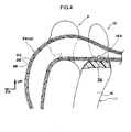
Fig. 4 is a side cross-sectional view showing an expansion state of the air belt in the air belt device according to the first exemplary embodiment of the present invention. -
Fig. 5 is a front elevation view showing, in frame format, a restraining state of a small occupant by the air belt device according to the first exemplary embodiment of the present invention. -
Fig. 6 is a front elevation view showing, in frame format, a main portion of an air belt device according to a second exemplary embodiment of the present invention. -
Fig. 7 is a front cross-sectional view showing, in frame format, a main portion of a four-point-type air belt device according to a third exemplary embodiment of the present invention. - An
air belt device 10 serving as an occupant restraining device for a vehicle according to a first exemplary embodiment of the present invention will be explained based onFigs. 1-5 . It should be noted that arrow FR, arrow UP and arrow W, which are appropriately noted in the respective drawings, respectively indicate a frontward direction (traveling direction), an upward direction and a vehicle width direction of a vehicle to which theair belt device 10 is applied. These respective directions substantially correspond to a frontward direction, an upward direction and a right side and left side in a seat width direction of a vehicle seat 11 to which theair belt device 10 is applied. - In
Fig. 1 , a non-use state of theair belt device 10 that is applied to the vehicle seat 11 is shown in a perspective view. As shown in this drawing, theair belt device 10 comprises aretractor 14 that takes up one end side of aseat belt 12 so as to be able to be pulled out. Theretractor 14 is disposed to the rear in a vehicle front-rear direction with respect to aseat back 16 configuring the vehicle seat 11 and fixed, for example, to a package tray rim or the like serving as a vehicle body. The other end side of theseat belt 12 is fixed by an unillustrated anchor to the side of a rear portion of aseat cushion 18 configuring the vehicle seat 11. - In this non-use state, the
seat belt 12 extends in a vehicle up-down direction at one end side in the width direction of the vehicle seat 11, and atongue plate 20 is provided at a substantially intermediate portion in the up-down direction thereof. Thetongue plate 20 is configured so as to be capable of coupling and release of the coupling with respect to abuckle 22 disposed at an opposite side in the width direction of the vehicle seat 11. - In the
air belt device 10, a configuration is provided in which, by coupling thetongue plate 20 with thebuckle 22, ashoulder belt portion 12A serving as an upper body restraining portion extending from a shoulder portion of the seat back 16 to thetongue plate 20 spans diagonally across an upper body of an occupant. In this state, theseat belt 12 is configured so as to restrain the upper body of the seated occupant P at theshoulder belt portion 12A as shown inFig. 2 , and so that a lap belt portion (illustration of which is omitted from the drawings) extending from thetongue plate 20 to the anchor restrains a hip portion of the seated occupant P. - Accordingly, the
air belt device 10 is configured as an air belt device having a three-point-type seat belt device as a base thereof. Further, in theair belt device 10, theretractor 14 is disposed to the rear of theseat back 16 as described above. As a result, theseat belt 12, which is put in an application state by the seated occupant P at the vehicle seat 11, is provided with a configuration in which a portion directly above theshoulder belt portion 12A is wound across ashoulder portion 16A (abelt insertion portion 32 which will be described later) of the seat back 16. In the present exemplary embodiment, a configuration is provided in which a shoulder anchor or the like that guides theseat belt 12 is not provided between theretractor 14 and theshoulder portion 16A of the seat back 16. - Further, at least one portion of the
seat belt 12, which portion includes theshoulder belt portion 12A, is configured as anair belt 24 serving as an expanding belt portion that receives gas supply from an unillustrated inflator to be expanded and deployed. In the application state of theseat belt 12 by the seated applicant P at the vehicle seat 11, theair belt 24 is established as at least a portion that is wound across theshoulder portion 16A of the seat back 16 and a portion that spans substantially the entire length of theshoulder belt portion 12A. - To supplement with regard to the
air belt 24, as shown inFig. 3A , theair belt 24 comprises as main portions thereof acover 26 serving as a belt main body, anelastic mesh webbing 28 that is provided at an inner side of thecover 26, and anair bag 30 that is provided in a folded state at an inner side of themesh webbing 28. - The
air belt 24 is configured so that, due to receiving gas supply from the unillustrated inflator arranged at theretractor 14 side or the anchor side and theair bag 30 being expanded, theentire air belt 24 is expanded and deployed as shown by the imaginary lines inFig. 2 and inFig. 3B andFig. 4 . A portion of theseat belt 12 other than theair belt 24 is joined with thecover 26 by stitching or the like. The inflator is configured such that, for example, in a case where (the inevitability of) a frontal collision of the vehicle is detected or predicted, the inflator is activated by an unillustrated ECU and supplies gas to theair bag 30. - Further, the
air belt device 10 comprises abelt insertion portion 32 for regulating a position of the seat belt 12 (air belt 24). Thebelt insertion portion 32 is formed as a recess by indenting a portion, in the seat width direction, of theshoulder portion 16A of the seat back 16 across the entire length thereof in the vehicle front-rear direction, so as to open upward in the vehicle up-down direction. A setting region of theair belt 24 of theseat belt 12 is slidably inserted into thebelt insertion portion 32. Theair belt 24 is configured so as to be made to enter into thebelt insertion portion 32 so as to be slidable in the longitudinal direction thereof, at least in the application state of theseat belt 12 by the seated occupant P at the vehicle seat 11. - Accordingly, the
belt insertion portion 32 has a width that is equal to or greater than a width of theair belt 24. Further, the width and the depth of thebelt insertion portion 32 is determined such that a portion (cross section) of theair belt 24 that is expanded directly above theshoulder portion 16A of the seat back 16 is inserted into thebelt insertion portion 32 by only about 1/3 of the up-down direction dimension thereof. In the present exemplary embodiment, theretractor 14 is disposed at the same position or lower in the vehicle up-down direction with respect to theshoulder portion 16A (bottom of the belt insertion portion 32) of the seat back 16. As a result, in theair belt device 10, a configuration is provided in which theair belt 24 can be inserted into the belt insertion portion 32 (wound across the bottom of the belt insertion portion 32) without using a shoulder anchor or the like that guides the seat belt 12 (air belt 24) as described above. - As shown in
Fig. 3 andFig. 4 , thebelt insertion portion 32 is formed integrally with the seat back 16 by indenting a portion of a cushion material (pad) 34 configuring the seat back 16 and providing anepidermal material 36 at the indentation. - Next, operation of the first exemplary embodiment will be explained.
- In the
air belt device 10 of the above configuration, when theseat belt 12 is applied, the seated occupant P at the vehicle seat 11 couples thetongue plate 20 with thebuckle 22 while pulling out theseat belt 12 from theretractor 14. As a result, as shown in frame format inFig. 2 , theshoulder belt portion 12A restrains the upper body of the seated occupant P, and the unillustrated lap belt portion restrains the hip portion of the seated occupant P. - When a frontal collision of the vehicle is detected or predicted, the ECU activates the inflator. When this happens, gas is supplied from the inflator to the
air bag 30 of theair belt 24, and theair belt 24 is expanded and deployed in a predetermined shape. As a result, the occupant is protected with respect to the frontal collision. - In this regard, in the present
air belt device 10, theair belt 24 is entered into thebelt insertion portion 32 formed at the seat back 16. As a result, in the expansion and deployment state (process) of theair belt 24, movement of theair belt 24 in the seat width direction is restricted by a pair ofrecess walls 32A of thebelt insertion portion 32 that face each other in the seat width direction. That is to say, the position of the expanded and deployedair belt 24 with respect to the vehicle seat 11 (occupant) is regulated. In particular, movement of theair belt 24 toward the seat width direction outer sides is restricted by therecess walls 32A at the seat width direction outer sides. - As a result, in the
air belt device 10, theair belt 24 is expanded and deployed at a position suited to protection of the occupant, and the occupant is effectively protected. Further, since thebelt insertion portion 32 is configured by indenting theshoulder portion 16A of the seat back 16, the position of theair belt 24 can be regulated, without occupying vehicle cabin space. - Due to the foregoing, in the
air belt device 10, there is no need to provide a guide member that occupies vehicle cabin space for positional regulation of theair belt 24. Accordingly, reduction in the number of parts and reduction in cost is achieved. Further, parts that protrude into the vehicle cabin space are reduced, and improvement in effective utilization and availability of limited vehicle cabin space, improvement in appearance and the like are achieved. - Further, in the
air belt device 10, a configuration is provided in which the air belt 24 (seat belt 12) is made to enter into thebelt insertion portion 32. As a result, as shown inFig. 5 , the seat belt 12 (particularly theshoulder belt portion 12A) can be properly applied with respect to an occupant whose sitting height is low, such as a child or the like. For example, in a comparative example in which thebelt insertion portion 32 is not provided, theshoulder belt portion 12A is easily interfered with by a neck portion for the seated occupant P whose relative sitting height is low, as shown by imaginary lines inFig. 5 . - In contrast, in the
air belt device 10, the portion across which theseat belt 12 is wound is a lower position with respect to the comparative example. As a result of this, theshoulder belt portion 12A is disposed at a position at which it is less likely to interfere with the neck portion for an occupant whose relative sitting height is low, as shown by solid lines inFig. 5 . Moreover, movement of theseat belt 12 toward the side of the neck portion of the seated occupant P is restricted by therecess wall 32A at the vehicle width direction inner side of thebelt insertion portion 32. As a result, in theair belt device 10, as discussed above, a contribution is made to properly applying theshoulder belt portion 12A to the seated occupant P having a small build whose sitting height is low, such as a child or the like. - Next, other exemplary embodiments of the present invention will be explained. It should be noted that, for parts and portions that are basically the same as in the above-described first exemplary embodiment or previously presented configurations, the same reference numerals as in the above-described first exemplary embodiment or previously presented configurations may be allotted thereto, and explanation and illustration thereof may be omitted in some cases.
- In
Fig. 6 , anair belt device 40 serving as an occupant restraining device for a vehicle according to a second exemplary embodiment of the present invention is shown in a frame format front elevation view. As shown in this drawing, theair belt device 40 differs from theair belt device 10, which is a three-point-type air belt device, in that it comprises a left and right pair ofseat belts 12 and is configured as a so-called four-point-type air belt device. - Specifically, in the left and
right seat belts 12, upper end sides thereof are respectively taken up byretractors 14, which are not illustrated in the drawings, and lower end sides thereof are respectively fixed at rear portions of aseat cushion 18 via anchors. Further, atongue plate 20 is provided at a substantially intermediate portion of one of theseat belts 12, and abuckle 22 is provided at a substantially intermediate portion of the other of theseat belts 12. As a result, in theair belt device 40, a configuration is provided such that, in a usage state in which thetongue plate 20 has been coupled with thebuckle 22, a left and right pair ofshoulder belt portions 12A restrain the state of the seated occupant P at the vehicle seat 11, as shown inFig. 6 . Further, in theair belt device 40 in this usage state, a configuration is provided such that lap belt portions 12B configured by the left andright seat belts 12 restrain the hip portion of the seated occupant P. - Further, in the
air belt device 40,belt insertion portions 32 are respectively formed at left andright shoulder portions 16A of the seat back 16. Accordingly, portions ofair belts 24 in the left andright seat belts 12 are respectively inserted into the correspondingbelt insertion portions 32. Other configurations in theair belt device 40 are the same as corresponding configurations of theair belt device 10, including portions that are not illustrated in the drawings. - Accordingly, it is possible to obtain basically similar effects by similar operation as in the
air belt device 10 according to the first exemplary embodiment, also by theair belt device 40 according to the second exemplary embodiment. In particular, in the four-point-typeair belt device 40, there are cases where the expanded and deployed left andright air belts 24 intervene so that repelling forces act against each other to the vehicle width direction outer sides as shown by imaginary lines inFig. 6 . Even in this case, in theair belt device 40, the left and rightbelt insertion portions 32 regulate the positions of therespective air belts 24 at proper positions. That is to say,recess walls 32A at the seat width direction outer sides of the respectivebelt insertion portions 32 support the reaction forces of theair belts 24, and the positions of therespective air belts 24 are regulated at proper positions. As a result, in theair belt device 40, the occupant protection effect by the left andright air belts 24 is high. - In
Fig. 7 , the main portion of anair belt device 50 serving as an occupant restraining device for a vehicle according to a third exemplary embodiment of the present invention is shown in a front cross-sectional view correspondingFig. 3B . As shown in this drawing, theair belt device 50, differs from theair belt device 10 according to the first exemplary embodiment in that athick belt 52 serving as a deformation regulation portion is provided within theair belt 24. - The
thick belt 52 is formed to be thick using, for example, a material (fiber) that is the same as that of theair bag 30 and is made to be integral with theair bag 30 by stitching or the like. It should be noted that thethick belt 52 may be made to be integral with thecover 26 or themesh webbing 28, rather than with theair bag 30. Thethick belt 52 is established in a predetermined range of theair belt 24 where it is inserted into thebelt insertion portion 32 at least in the application state of theseat belt 12 by the occupant, and at a lower side in the vehicle up-down direction (bottom side of the belt insertion portion 32). - In the
air belt device 50, a configuration is provided such that a deployment shape of theair belt 24 is regulated by thethick belt 52 to a shape in which a lower end portion is substantially flat as shown inFig. 7 . Other configurations of theair belt device 50 are the same as corresponding configurations of theair belt device 10 or theair belt device 40, including portions that are not illustrated in the drawings. - Accordingly, it is possible to obtain basically similar effects by similar operation as in the
air belt device air belt device 50 according to the third exemplary embodiment. In particular, in theair belt device 50, since the lower end of theair belt 24 in the deployment process or deployment state is substantially flat, the air belt 24 (seat belt 12) is less likely to roll with respect to force in the seat width direction. As a result, in theair belt device 50, positional variation of theair belt 24 in the seat width direction with respect to thebelt insertion portion 32 is even less likely to occur, and theair belt 24 is expanded and deployed at a position suited to protection of the occupant and contributes to effective protection of the occupant with greater certainty. - It should be noted that, in the respective exemplary embodiments described above, although examples in which the
seat belt 12 comprises theair belt 24 have been shown, the present invention is not limited thereto. The present invention may be applied, for example, to a three-point-type or four-point-type seat belt device in which theseat belt 12 does not comprise theair belt 24. In this case, as shown inFig. 5 , by providing thebelt insertion portion 32, a contribution is made to properly applying the seat belt 12 (particularly theshoulder belt portion 12A) with respect to a small-build occupant. - Further, in the exemplary embodiments described above, although examples in which the
belt insertion portion 32 always causes theair belt 24 to be inserted therein have been shown, the present invention is not limited thereto. For example, in a configuration in which theseat belt 12 comprises theair belt 24, a configuration may be provided wherein a belt insertion portion into which theair belt 24 is inserted accompanying expansion and deployment of theair belt 24 is provided at theshoulder portion 16A of the seat back 16. For example, in a configuration in which theepidermal material 36 ordinarily covers an opening end (upper end) of the recess formed in thecushion material 34, a configuration may be provided wherein a tear portion of theepidermal material 36 is torn by deployment pressure of theair belt 24, or a configuration may be provided wherein, by forming theepidermal material 36 at a position covering the recess with a material having high elasticity, theair belt 24 is inserted into the belt insertion portion accompanying expansion and deployment. - Furthermore, in the exemplary embodiments described above, although examples in which the
retractor 14 is disposed to the rear in the vehicle front-rear direction with respect to the seat back 16 have been shown, the present invention is not limited thereto. As long as the present invention has a configuration in which a portion in the longitudinal direction of theseat belt 12 or theair belt 24 is disposed along (wound across) at least a portion in the vehicle front-rear direction of theshoulder portion 16A of the seat back 16, it is possible to apply the present invention. Accordingly, the present invention can be applied, for example, to a configuration wherein theretractor 14 is disposed within the seat back 16, and theseat belt 12 orair belt 24 is led out from theshoulder portion 16A and disposed along theshoulder portion 16A. In this case, thebelt insertion portion 32 may be provided toward the vehicle front with respect to a belt lead-out portion of theshoulder portion 16A.
Claims (5)
- An occupant restraining device for a vehicle, comprising:a seat belt comprising an upper body restraining portion for restraining an upper body of an occupant, the seat belt being pulled out from a retractor when applied to the occupant; anda belt insertion portion that is formed by indenting a portion, in a seat width direction, of an upper end of a seat back, and into which a portion of the seat belt at an upper side of the upper body restraining portion is made to enter.
- The occupant restraining device for a vehicle of claim 1, wherein an expanding belt portion that is expanded and deployed by gas supply is provided at a portion of the seat belt that includes the portion that is made to enter into the belt insertion portion and the upper body restraining portion.
- An occupant restraining device for a vehicle, comprising:a seat belt comprising an upper body restraining portion for restraining an upper body of an occupant, the seat belt being pulled out from a retractor when applied to the occupant;an expanding belt portion which is provided at a portion of the seat belt that includes the upper body restraining portion and a portion at an upper side of the upper body restraining portion, and which is expanded and deployed by gas supply; anda belt insertion portion which includes a recess formed by indenting a portion, in a seat width direction, of an upper end of a seat back, and in which a lower portion, in a vehicle up-down direction, of the expanding belt portion is made to enter into the recess when the expanding belt portion is deployed.
- The occupant restraining device for a vehicle of claim 2 or claim 3, comprising a left and right pair of the seat belt, each seat belt in the pair being provided with the expanding belt portion, wherein a left and right pair of the belt insertion portion is provided at the upper end of the seat back.
- The occupant restraining device for a vehicle of any one of claim 2 through claim 4, wherein a planar surface maintenance structure for maintaining a planar surface shape of a contact surface contacting with a bottom surface of the belt insertion portion when the expanding belt portion is deployed is provided at the expanding belt portion.
Applications Claiming Priority (2)
| Application Number | Priority Date | Filing Date | Title |
|---|---|---|---|
| JP2008288753A JP4380778B1 (en) | 2008-11-11 | 2008-11-11 | Vehicle occupant restraint system |
| PCT/JP2009/059324 WO2010055705A1 (en) | 2008-11-11 | 2009-05-21 | Occupant restraint device for vehicles |
Publications (3)
| Publication Number | Publication Date |
|---|---|
| EP2345561A1 true EP2345561A1 (en) | 2011-07-20 |
| EP2345561A4 EP2345561A4 (en) | 2012-04-04 |
| EP2345561B1 EP2345561B1 (en) | 2013-10-23 |
Family
ID=41459751
Family Applications (1)
| Application Number | Title | Priority Date | Filing Date |
|---|---|---|---|
| EP09825958.3A Not-in-force EP2345561B1 (en) | 2008-11-11 | 2009-05-21 | Occupant restraint device for vehicles |
Country Status (5)
| Country | Link |
|---|---|
| US (1) | US8246077B2 (en) |
| EP (1) | EP2345561B1 (en) |
| JP (1) | JP4380778B1 (en) |
| CN (1) | CN101965280A (en) |
| WO (1) | WO2010055705A1 (en) |
Families Citing this family (15)
| Publication number | Priority date | Publication date | Assignee | Title |
|---|---|---|---|---|
| DE102010053311A1 (en) * | 2010-12-02 | 2012-06-06 | Daimler Ag | Belt for a safety belt of a vehicle |
| EP2804788B1 (en) * | 2012-01-17 | 2017-08-23 | Helite S.a.r.l. | Protecting device for the head and the neck of an idividual |
| JP5850008B2 (en) * | 2013-08-21 | 2016-02-03 | トヨタ自動車株式会社 | Air belt device |
| GB2532286A (en) * | 2014-11-17 | 2016-05-18 | Ford Global Tech Llc | A seat back |
| JP6555661B2 (en) * | 2015-03-31 | 2019-08-07 | 株式会社Subaru | Crew protection device |
| CN105253099A (en) * | 2015-10-22 | 2016-01-20 | 成都易默生汽车技术有限公司 | Intelligent automobile auxiliary safety device |
| JP6254634B2 (en) * | 2016-03-31 | 2017-12-27 | 株式会社Subaru | Crew protection device |
| JP6677104B2 (en) * | 2016-06-27 | 2020-04-08 | トヨタ紡織株式会社 | Vehicle interior structure |
| JP6486994B2 (en) * | 2017-06-26 | 2019-03-20 | 株式会社タチエス | Vehicle seat |
| US10336278B2 (en) * | 2017-07-14 | 2019-07-02 | Autoliv Asp, Inc. | Inflatable airbag harness assemblies |
| DE102018213279A1 (en) * | 2018-08-08 | 2020-02-13 | Autoliv Development Ab | Load-bearing structural part for a vehicle seat |
| KR102614153B1 (en) * | 2018-11-26 | 2023-12-13 | 현대자동차주식회사 | Air bag apparatus for protecting head of passenger |
| JP7294298B2 (en) * | 2020-10-22 | 2023-06-20 | トヨタ自動車株式会社 | passenger protection device |
| CN115009127B (en) * | 2022-04-29 | 2024-05-07 | 重庆长安汽车股份有限公司 | Front collision restraint system of zero gravity seat and vehicle |
| KR20240017246A (en) * | 2022-07-29 | 2024-02-07 | 현대자동차주식회사 | Airbag System |
Family Cites Families (20)
| Publication number | Priority date | Publication date | Assignee | Title |
|---|---|---|---|---|
| US4817754A (en) * | 1987-04-27 | 1989-04-04 | Mazda Motor Corporation | Automotive seat belt system and retractor device for seat belt system |
| JPH0757592B2 (en) * | 1988-10-26 | 1995-06-21 | マツダ株式会社 | Car seat belt equipment |
| JPH0448066A (en) | 1990-06-14 | 1992-02-18 | Kobe Steel Ltd | Method for vacuum-depositing copper |
| JPH0448066U (en) * | 1990-08-31 | 1992-04-23 | ||
| DE69732294T2 (en) | 1996-07-02 | 2005-12-22 | Zodiac Automotive Us Inc., Tempe | INFLATABLE TUBULAR HULL RESTRAINT SYSTEM |
| US5839753A (en) | 1997-03-31 | 1998-11-24 | Simula Inc. | Inflatable tubular torso restraint system |
| FR2757466B1 (en) * | 1996-12-24 | 1999-03-26 | Ecia Equip Composants Ind Auto | SEAT FOR MOTOR VEHICLE WITH ON-BOARD SEAT BELT AND SEAT ARRANGEMENT IN THE VEHICLE INTERIOR |
| US5851055A (en) | 1997-03-13 | 1998-12-22 | Universal Propulsion Company, Inc. | Inflatable passenger-size adjustable torso belt system including enclosure mount and method of passenger restraint |
| BR9813589A (en) * | 1997-12-16 | 2000-10-10 | Magna Interior Sys Inc | Child restraint seat set. |
| FR2777518B1 (en) * | 1998-04-17 | 2000-06-16 | Faure Bertrand Equipements Sa | MOTOR VEHICLE SEAT BACKREST |
| JP2000025546A (en) | 1998-07-16 | 2000-01-25 | Honda Motor Co Ltd | Seat belt equipment |
| US6237945B1 (en) * | 1999-02-26 | 2001-05-29 | Lear Corporation | Passenger restraint system |
| US6382666B1 (en) * | 2000-03-13 | 2002-05-07 | Universal Propulsion Company, Inc. | Arrangement for providing deployment of inflatable member coaxially with safety belt portion and related method |
| US6705641B2 (en) * | 2002-03-08 | 2004-03-16 | Autoliv Asp, Inc. | Inflatable seat belt system |
| JP4072189B2 (en) | 2002-08-09 | 2008-04-09 | 株式会社東海理化電機製作所 | child seat |
| DE10251081B4 (en) * | 2002-11-02 | 2005-06-16 | Janz, Norbert, Dipl.-Ing. | Belt deflector on a seat, in particular a vehicle seat |
| FR2851974B1 (en) | 2003-03-04 | 2006-03-24 | Eads Sogerma Services | RESTRAINT SYSTEM FOR A PERSON OCCUPYING A VEHICLE SEAT |
| JP4775032B2 (en) | 2005-09-26 | 2011-09-21 | タカタ株式会社 | Crew restraint system |
| DE102005047272B3 (en) * | 2005-10-01 | 2007-04-26 | Keiper Gmbh & Co.Kg | Vehicle seat e.g. motor vehicle rear seat, has belt force target area and cross beam attachment area arranged offset to each other in seat transverse direction |
| US8172327B2 (en) * | 2009-02-24 | 2012-05-08 | Honda Motor Co., Ltd. | Integrated seat fold-down lever/belt exit |
-
2008
- 2008-11-11 JP JP2008288753A patent/JP4380778B1/en not_active Expired - Fee Related
-
2009
- 2009-05-21 US US12/920,647 patent/US8246077B2/en not_active Expired - Fee Related
- 2009-05-21 EP EP09825958.3A patent/EP2345561B1/en not_active Not-in-force
- 2009-05-21 WO PCT/JP2009/059324 patent/WO2010055705A1/en not_active Ceased
- 2009-05-21 CN CN2009801064370A patent/CN101965280A/en active Pending
Also Published As
| Publication number | Publication date |
|---|---|
| CN101965280A (en) | 2011-02-02 |
| EP2345561B1 (en) | 2013-10-23 |
| US20110006508A1 (en) | 2011-01-13 |
| EP2345561A4 (en) | 2012-04-04 |
| WO2010055705A1 (en) | 2010-05-20 |
| JP2010115945A (en) | 2010-05-27 |
| JP4380778B1 (en) | 2009-12-09 |
| US8246077B2 (en) | 2012-08-21 |
Similar Documents
| Publication | Publication Date | Title |
|---|---|---|
| US8246077B2 (en) | Occupant restraining device for a vehicle | |
| US7163236B2 (en) | Vehicle occupant restraint system and vehicle occupant restraint method | |
| EP2711250B1 (en) | Seat structural member and vehicle seat using same | |
| US9434342B2 (en) | Vehicle seat equipped with side airbag device | |
| EP3772438B1 (en) | Airbag device | |
| US20100164207A1 (en) | Airbelt apparatus for vehicle | |
| JP2007210429A (en) | Air belt device for vehicle | |
| JP7001914B2 (en) | Vehicle seat | |
| JP7727843B2 (en) | Airbag device | |
| JP2010105544A (en) | Occupant restraint device | |
| JP2010143422A (en) | Lateral-collision head restraining device | |
| JP2010143371A (en) | Occupant restraint device for vehicle | |
| JP2010083414A (en) | Occupant restraint system | |
| JP7831357B2 (en) | Vehicle occupant restraint device | |
| JP2007223524A (en) | Crew protection device | |
| EP1745987B1 (en) | Occupant restraint apparatus | |
| JP7129157B2 (en) | Airbag | |
| JP2006290259A (en) | Seat belt device | |
| JP4946444B2 (en) | Crew protection device | |
| JP2019014457A (en) | Vehicle occupant restraint system | |
| JP2011005910A (en) | Seat belt device | |
| JP6937144B2 (en) | Crew protection device | |
| JP4702007B2 (en) | Seat belt device | |
| KR20250135695A (en) | Occupant restraint device for vehicle | |
| JP6662309B2 (en) | Rear seat side airbag device |
Legal Events
| Date | Code | Title | Description |
|---|---|---|---|
| PUAI | Public reference made under article 153(3) epc to a published international application that has entered the european phase |
Free format text: ORIGINAL CODE: 0009012 |
|
| 17P | Request for examination filed |
Effective date: 20100920 |
|
| AK | Designated contracting states |
Kind code of ref document: A1 Designated state(s): AT BE BG CH CY CZ DE DK EE ES FI FR GB GR HR HU IE IS IT LI LT LU LV MC MK MT NL NO PL PT RO SE SI SK TR |
|
| AX | Request for extension of the european patent |
Extension state: AL BA RS |
|
| DAX | Request for extension of the european patent (deleted) | ||
| A4 | Supplementary search report drawn up and despatched |
Effective date: 20120301 |
|
| RIC1 | Information provided on ipc code assigned before grant |
Ipc: B60R 22/26 20060101ALI20120224BHEP Ipc: B60R 22/14 20060101ALI20120224BHEP Ipc: B60R 21/18 20060101ALI20120224BHEP Ipc: B60N 2/42 20060101ALI20120224BHEP Ipc: B60N 2/68 20060101AFI20120224BHEP |
|
| REG | Reference to a national code |
Ref country code: DE Ref legal event code: R079 Ref document number: 602009019705 Country of ref document: DE Free format text: PREVIOUS MAIN CLASS: B60R0021180000 Ipc: B60N0002680000 |
|
| RIC1 | Information provided on ipc code assigned before grant |
Ipc: B60N 2/42 20060101ALI20121126BHEP Ipc: B60R 21/18 20060101ALI20121126BHEP Ipc: B60R 22/14 20060101ALI20121126BHEP Ipc: B60R 22/26 20060101ALI20121126BHEP Ipc: B60N 2/68 20060101AFI20121126BHEP |
|
| RAP1 | Party data changed (applicant data changed or rights of an application transferred) |
Owner name: TOYOTA JIDOSHA KABUSHIKI KAISHA |
|
| GRAP | Despatch of communication of intention to grant a patent |
Free format text: ORIGINAL CODE: EPIDOSNIGR1 |
|
| INTG | Intention to grant announced |
Effective date: 20130621 |
|
| GRAS | Grant fee paid |
Free format text: ORIGINAL CODE: EPIDOSNIGR3 |
|
| GRAA | (expected) grant |
Free format text: ORIGINAL CODE: 0009210 |
|
| AK | Designated contracting states |
Kind code of ref document: B1 Designated state(s): AT BE BG CH CY CZ DE DK EE ES FI FR GB GR HR HU IE IS IT LI LT LU LV MC MK MT NL NO PL PT RO SE SI SK TR |
|
| REG | Reference to a national code |
Ref country code: GB Ref legal event code: FG4D |
|
| REG | Reference to a national code |
Ref country code: CH Ref legal event code: EP |
|
| REG | Reference to a national code |
Ref country code: AT Ref legal event code: REF Ref document number: 637373 Country of ref document: AT Kind code of ref document: T Effective date: 20131115 |
|
| REG | Reference to a national code |
Ref country code: IE Ref legal event code: FG4D |
|
| REG | Reference to a national code |
Ref country code: DE Ref legal event code: R096 Ref document number: 602009019705 Country of ref document: DE Effective date: 20131219 |
|
| REG | Reference to a national code |
Ref country code: NL Ref legal event code: VDEP Effective date: 20131023 |
|
| REG | Reference to a national code |
Ref country code: AT Ref legal event code: MK05 Ref document number: 637373 Country of ref document: AT Kind code of ref document: T Effective date: 20131023 |
|
| REG | Reference to a national code |
Ref country code: LT Ref legal event code: MG4D |
|
| PG25 | Lapsed in a contracting state [announced via postgrant information from national office to epo] |
Ref country code: NL Free format text: LAPSE BECAUSE OF FAILURE TO SUBMIT A TRANSLATION OF THE DESCRIPTION OR TO PAY THE FEE WITHIN THE PRESCRIBED TIME-LIMIT Effective date: 20131023 Ref country code: BE Free format text: LAPSE BECAUSE OF FAILURE TO SUBMIT A TRANSLATION OF THE DESCRIPTION OR TO PAY THE FEE WITHIN THE PRESCRIBED TIME-LIMIT Effective date: 20131023 Ref country code: SE Free format text: LAPSE BECAUSE OF FAILURE TO SUBMIT A TRANSLATION OF THE DESCRIPTION OR TO PAY THE FEE WITHIN THE PRESCRIBED TIME-LIMIT Effective date: 20131023 Ref country code: NO Free format text: LAPSE BECAUSE OF FAILURE TO SUBMIT A TRANSLATION OF THE DESCRIPTION OR TO PAY THE FEE WITHIN THE PRESCRIBED TIME-LIMIT Effective date: 20140123 Ref country code: IS Free format text: LAPSE BECAUSE OF FAILURE TO SUBMIT A TRANSLATION OF THE DESCRIPTION OR TO PAY THE FEE WITHIN THE PRESCRIBED TIME-LIMIT Effective date: 20140223 Ref country code: FI Free format text: LAPSE BECAUSE OF FAILURE TO SUBMIT A TRANSLATION OF THE DESCRIPTION OR TO PAY THE FEE WITHIN THE PRESCRIBED TIME-LIMIT Effective date: 20131023 Ref country code: LT Free format text: LAPSE BECAUSE OF FAILURE TO SUBMIT A TRANSLATION OF THE DESCRIPTION OR TO PAY THE FEE WITHIN THE PRESCRIBED TIME-LIMIT Effective date: 20131023 Ref country code: HR Free format text: LAPSE BECAUSE OF FAILURE TO SUBMIT A TRANSLATION OF THE DESCRIPTION OR TO PAY THE FEE WITHIN THE PRESCRIBED TIME-LIMIT Effective date: 20131023 |
|
| PG25 | Lapsed in a contracting state [announced via postgrant information from national office to epo] |
Ref country code: LV Free format text: LAPSE BECAUSE OF FAILURE TO SUBMIT A TRANSLATION OF THE DESCRIPTION OR TO PAY THE FEE WITHIN THE PRESCRIBED TIME-LIMIT Effective date: 20131023 Ref country code: ES Free format text: LAPSE BECAUSE OF FAILURE TO SUBMIT A TRANSLATION OF THE DESCRIPTION OR TO PAY THE FEE WITHIN THE PRESCRIBED TIME-LIMIT Effective date: 20131023 Ref country code: CY Free format text: LAPSE BECAUSE OF FAILURE TO SUBMIT A TRANSLATION OF THE DESCRIPTION OR TO PAY THE FEE WITHIN THE PRESCRIBED TIME-LIMIT Effective date: 20131023 Ref country code: AT Free format text: LAPSE BECAUSE OF FAILURE TO SUBMIT A TRANSLATION OF THE DESCRIPTION OR TO PAY THE FEE WITHIN THE PRESCRIBED TIME-LIMIT Effective date: 20131023 |
|
| PG25 | Lapsed in a contracting state [announced via postgrant information from national office to epo] |
Ref country code: PT Free format text: LAPSE BECAUSE OF FAILURE TO SUBMIT A TRANSLATION OF THE DESCRIPTION OR TO PAY THE FEE WITHIN THE PRESCRIBED TIME-LIMIT Effective date: 20140224 |
|
| REG | Reference to a national code |
Ref country code: DE Ref legal event code: R097 Ref document number: 602009019705 Country of ref document: DE |
|
| PG25 | Lapsed in a contracting state [announced via postgrant information from national office to epo] |
Ref country code: EE Free format text: LAPSE BECAUSE OF FAILURE TO SUBMIT A TRANSLATION OF THE DESCRIPTION OR TO PAY THE FEE WITHIN THE PRESCRIBED TIME-LIMIT Effective date: 20131023 |
|
| PG25 | Lapsed in a contracting state [announced via postgrant information from national office to epo] |
Ref country code: SK Free format text: LAPSE BECAUSE OF FAILURE TO SUBMIT A TRANSLATION OF THE DESCRIPTION OR TO PAY THE FEE WITHIN THE PRESCRIBED TIME-LIMIT Effective date: 20131023 Ref country code: RO Free format text: LAPSE BECAUSE OF FAILURE TO SUBMIT A TRANSLATION OF THE DESCRIPTION OR TO PAY THE FEE WITHIN THE PRESCRIBED TIME-LIMIT Effective date: 20131023 Ref country code: CZ Free format text: LAPSE BECAUSE OF FAILURE TO SUBMIT A TRANSLATION OF THE DESCRIPTION OR TO PAY THE FEE WITHIN THE PRESCRIBED TIME-LIMIT Effective date: 20131023 Ref country code: IT Free format text: LAPSE BECAUSE OF FAILURE TO SUBMIT A TRANSLATION OF THE DESCRIPTION OR TO PAY THE FEE WITHIN THE PRESCRIBED TIME-LIMIT Effective date: 20131023 Ref country code: PL Free format text: LAPSE BECAUSE OF FAILURE TO SUBMIT A TRANSLATION OF THE DESCRIPTION OR TO PAY THE FEE WITHIN THE PRESCRIBED TIME-LIMIT Effective date: 20131023 |
|
| PLBE | No opposition filed within time limit |
Free format text: ORIGINAL CODE: 0009261 |
|
| STAA | Information on the status of an ep patent application or granted ep patent |
Free format text: STATUS: NO OPPOSITION FILED WITHIN TIME LIMIT |
|
| PG25 | Lapsed in a contracting state [announced via postgrant information from national office to epo] |
Ref country code: DK Free format text: LAPSE BECAUSE OF FAILURE TO SUBMIT A TRANSLATION OF THE DESCRIPTION OR TO PAY THE FEE WITHIN THE PRESCRIBED TIME-LIMIT Effective date: 20131023 |
|
| 26N | No opposition filed |
Effective date: 20140724 |
|
| REG | Reference to a national code |
Ref country code: DE Ref legal event code: R097 Ref document number: 602009019705 Country of ref document: DE Effective date: 20140724 |
|
| PG25 | Lapsed in a contracting state [announced via postgrant information from national office to epo] |
Ref country code: LU Free format text: LAPSE BECAUSE OF FAILURE TO SUBMIT A TRANSLATION OF THE DESCRIPTION OR TO PAY THE FEE WITHIN THE PRESCRIBED TIME-LIMIT Effective date: 20140521 |
|
| REG | Reference to a national code |
Ref country code: CH Ref legal event code: PL |
|
| GBPC | Gb: european patent ceased through non-payment of renewal fee |
Effective date: 20140521 |
|
| PG25 | Lapsed in a contracting state [announced via postgrant information from national office to epo] |
Ref country code: LI Free format text: LAPSE BECAUSE OF NON-PAYMENT OF DUE FEES Effective date: 20140531 Ref country code: CH Free format text: LAPSE BECAUSE OF NON-PAYMENT OF DUE FEES Effective date: 20140531 Ref country code: MC Free format text: LAPSE BECAUSE OF FAILURE TO SUBMIT A TRANSLATION OF THE DESCRIPTION OR TO PAY THE FEE WITHIN THE PRESCRIBED TIME-LIMIT Effective date: 20131023 |
|
| REG | Reference to a national code |
Ref country code: DE Ref legal event code: R084 Ref document number: 602009019705 Country of ref document: DE |
|
| REG | Reference to a national code |
Ref country code: IE Ref legal event code: MM4A |
|
| PG25 | Lapsed in a contracting state [announced via postgrant information from national office to epo] |
Ref country code: SI Free format text: LAPSE BECAUSE OF FAILURE TO SUBMIT A TRANSLATION OF THE DESCRIPTION OR TO PAY THE FEE WITHIN THE PRESCRIBED TIME-LIMIT Effective date: 20131023 |
|
| REG | Reference to a national code |
Ref country code: FR Ref legal event code: ST Effective date: 20150130 |
|
| REG | Reference to a national code |
Ref country code: DE Ref legal event code: R084 Ref document number: 602009019705 Country of ref document: DE Effective date: 20150223 |
|
| PG25 | Lapsed in a contracting state [announced via postgrant information from national office to epo] |
Ref country code: IE Free format text: LAPSE BECAUSE OF NON-PAYMENT OF DUE FEES Effective date: 20140521 |
|
| PG25 | Lapsed in a contracting state [announced via postgrant information from national office to epo] |
Ref country code: GB Free format text: LAPSE BECAUSE OF NON-PAYMENT OF DUE FEES Effective date: 20140521 Ref country code: FR Free format text: LAPSE BECAUSE OF NON-PAYMENT OF DUE FEES Effective date: 20140602 |
|
| PGFP | Annual fee paid to national office [announced via postgrant information from national office to epo] |
Ref country code: DE Payment date: 20150512 Year of fee payment: 7 |
|
| PG25 | Lapsed in a contracting state [announced via postgrant information from national office to epo] |
Ref country code: MT Free format text: LAPSE BECAUSE OF FAILURE TO SUBMIT A TRANSLATION OF THE DESCRIPTION OR TO PAY THE FEE WITHIN THE PRESCRIBED TIME-LIMIT Effective date: 20131023 |
|
| PG25 | Lapsed in a contracting state [announced via postgrant information from national office to epo] |
Ref country code: GR Free format text: LAPSE BECAUSE OF FAILURE TO SUBMIT A TRANSLATION OF THE DESCRIPTION OR TO PAY THE FEE WITHIN THE PRESCRIBED TIME-LIMIT Effective date: 20140124 Ref country code: BG Free format text: LAPSE BECAUSE OF FAILURE TO SUBMIT A TRANSLATION OF THE DESCRIPTION OR TO PAY THE FEE WITHIN THE PRESCRIBED TIME-LIMIT Effective date: 20131023 |
|
| PG25 | Lapsed in a contracting state [announced via postgrant information from national office to epo] |
Ref country code: HU Free format text: LAPSE BECAUSE OF FAILURE TO SUBMIT A TRANSLATION OF THE DESCRIPTION OR TO PAY THE FEE WITHIN THE PRESCRIBED TIME-LIMIT; INVALID AB INITIO Effective date: 20090521 Ref country code: TR Free format text: LAPSE BECAUSE OF FAILURE TO SUBMIT A TRANSLATION OF THE DESCRIPTION OR TO PAY THE FEE WITHIN THE PRESCRIBED TIME-LIMIT Effective date: 20131023 |
|
| REG | Reference to a national code |
Ref country code: DE Ref legal event code: R119 Ref document number: 602009019705 Country of ref document: DE |
|
| PG25 | Lapsed in a contracting state [announced via postgrant information from national office to epo] |
Ref country code: DE Free format text: LAPSE BECAUSE OF NON-PAYMENT OF DUE FEES Effective date: 20161201 |
|
| PG25 | Lapsed in a contracting state [announced via postgrant information from national office to epo] |
Ref country code: MK Free format text: LAPSE BECAUSE OF FAILURE TO SUBMIT A TRANSLATION OF THE DESCRIPTION OR TO PAY THE FEE WITHIN THE PRESCRIBED TIME-LIMIT Effective date: 20131023 |