EP2345556B1 - Transport vehicle with a locking device - Google Patents
Transport vehicle with a locking device Download PDFInfo
- Publication number
- EP2345556B1 EP2345556B1 EP11150952.7A EP11150952A EP2345556B1 EP 2345556 B1 EP2345556 B1 EP 2345556B1 EP 11150952 A EP11150952 A EP 11150952A EP 2345556 B1 EP2345556 B1 EP 2345556B1
- Authority
- EP
- European Patent Office
- Prior art keywords
- frame
- locking
- support structure
- auxiliary frame
- transport vehicle
- Prior art date
- Legal status (The legal status is an assumption and is not a legal conclusion. Google has not performed a legal analysis and makes no representation as to the accuracy of the status listed.)
- Active
Links
- 238000009434 installation Methods 0.000 claims description 20
- 229910000831 Steel Inorganic materials 0.000 claims description 16
- 239000010959 steel Substances 0.000 claims description 16
- 238000011068 loading method Methods 0.000 description 6
- 238000005452 bending Methods 0.000 description 3
- 238000010276 construction Methods 0.000 description 3
- 230000008878 coupling Effects 0.000 description 3
- 238000010168 coupling process Methods 0.000 description 3
- 238000005859 coupling reaction Methods 0.000 description 3
- 239000004519 grease Substances 0.000 description 3
- 239000000725 suspension Substances 0.000 description 3
- 230000004075 alteration Effects 0.000 description 2
- 238000005461 lubrication Methods 0.000 description 2
- 210000002445 nipple Anatomy 0.000 description 2
- 229910000746 Structural steel Inorganic materials 0.000 description 1
- 239000006096 absorbing agent Substances 0.000 description 1
- 230000001627 detrimental effect Effects 0.000 description 1
- 230000005484 gravity Effects 0.000 description 1
- 230000035939 shock Effects 0.000 description 1
- 239000002699 waste material Substances 0.000 description 1
Images


Classifications
-
- B—PERFORMING OPERATIONS; TRANSPORTING
- B62—LAND VEHICLES FOR TRAVELLING OTHERWISE THAN ON RAILS
- B62D—MOTOR VEHICLES; TRAILERS
- B62D21/00—Understructures, i.e. chassis frame on which a vehicle body may be mounted
- B62D21/09—Means for mounting load bearing surfaces
-
- B—PERFORMING OPERATIONS; TRANSPORTING
- B62—LAND VEHICLES FOR TRAVELLING OTHERWISE THAN ON RAILS
- B62D—MOTOR VEHICLES; TRAILERS
- B62D33/00—Superstructures for load-carrying vehicles
- B62D33/08—Superstructures for load-carrying vehicles comprising adjustable means
-
- B—PERFORMING OPERATIONS; TRANSPORTING
- B62—LAND VEHICLES FOR TRAVELLING OTHERWISE THAN ON RAILS
- B62D—MOTOR VEHICLES; TRAILERS
- B62D21/00—Understructures, i.e. chassis frame on which a vehicle body may be mounted
- B62D21/12—Understructures, i.e. chassis frame on which a vehicle body may be mounted assembled from readily detachable parts
-
- B—PERFORMING OPERATIONS; TRANSPORTING
- B62—LAND VEHICLES FOR TRAVELLING OTHERWISE THAN ON RAILS
- B62D—MOTOR VEHICLES; TRAILERS
- B62D27/00—Connections between superstructure or understructure sub-units
- B62D27/06—Connections between superstructure or understructure sub-units readily releasable
Definitions
- the present invention relates to an arrangement in the frame of a transport vehicle, which arrangement includes
- the invention also relates to an installation kit for forming an arrangement in the frame of a transport vehicle.
- a general-purpose skip can be raised from the ground onto a truck, and lowered off the truck onto the ground.
- the hook-skip device is installed on top of the frame of the truck, so that the skip with the auxiliary frame rises as much as 200 millimetres above the frame.
- the load height rises, which hinders loading and unloading.
- useful load height is lost and with high loads driving under bridges, for example, can cause problems.
- the centre of gravity of the load also rises, which reduces the vehicle's stability.
- the hook-skip device is suitable only for simple skips.
- the hook-skip device reduces the payload, as a hook-skip device can weight as much as 1500 kilos.
- cable or chain -driven skip devices are also used, these being slightly lighter than the hook-skip device.
- the aforementioned hook-skip device is quick to use, but it is unsuitable, for example, for handling load bodies and especial device totalities.
- the attachment of the skip is uncertain.
- An arrangement is also known, in which an auxiliary frame for a superstructure is supported on top of the frame of a transport vehicle and is fastened using separate locking elements. Particularly the opening of the locking is labourious, so that the arrangement is not applied in daily use.
- the locking elements are wedges, the removal of which can even take more than one hour while in some applications the superstructure will prevent the removal of the wedges in field conditions.
- the locking element includes several wedges, which can detach during transport. Thus, despite the plurality of locking elements, the fastening of the arrangement is not achieved. The wedges also wear in use if they are removed repeatedly. The detaching and attaching of the wedges demands going on top of the frame, which is a serious safety risk.
- US patent number 5829946 discloses a simple waste-container attachment to a truck incorporating a waste press.
- US patent number 5738479 discloses a system of modular attachments for a railcar or truck trailer to convert the trailer to various uses is disclosed.
- a system of compressed air driven locking pins allows the various modules to be readily secured to or removed from the trailer chassis.
- Air suspension shock absorbers permit the load to be weighed on the car or trailer.
- the present invention is intended to create a new type of arrangement in the frame of a transport vehicle, which is low and sturdy, as well as being able to be rapidly opened and connected.
- the invention is intended to create a new type of transport vehicle, which is more versatile in use than previously and more widely adaptable.
- the invention is intended to create a new type of installation kit for forming an arrangement for a transport-vehicle frame, which is compact and requires only a small installation space.
- the locking can be easily and rapidly opened and connected.
- the speed and reliability are achieved by fitting most of the locking elements permanently to the vehicle. This avoids loose parts that are easily lost.
- the locking has no gaps and holds in all directions.
- the arrangement can be used successfully without tools and, above all, quickly.
- the superstructure can thus be changed even several times a day, so that the vehicle can be used versatilely for different transport purposes.
- the arrangement is also suitable for use with different device totalities.
- the installation kit itself is also compact and can easily be fitted as part of the frames of different types of vehicle.
- Figures 1a - c show transport vehicles that are, as such, conventional, which in this case are trucks.
- the trucks shown have different types of chassis, with different types of superstructure on them.
- each truck is designed and manufactured for a specific tasks.
- the frames of the trucks are subject to torsion stress.
- auxiliary frames which extend to nearly the entire length of the truck, have been installed on top of the frames.
- the frame and the auxiliary frame together then form a functional totality, which is sufficiently stiff against loadings, especially bending.
- the auxiliary frames 10 are shown by diagonal shading.
- the truck in Figure 1a is equipped with a concrete container, the auxiliary frame being supported on the frame 11 by eight attachments 12 on each side of the frame.
- the auxiliary frame 10 of the concrete mixer is supported on the truck's frame 11 by thirteen attachments 12 on each side of the frame.
- Figure 1c shows a hook-skip device, the auxiliary frame 10 of which is supported on the truck's frame 11 by five attachments 12 on each side of the frame. All the vehicles shown are adapted for a single function. Different types of simple skips and containers can be attached only to the hook-skip device.
- the aforementioned attachments can be replaced with a known conical-pin arrangement, in which the openings arranged in the superstructure's auxiliary frame are adapted onto relatively large conical pins arranged vertically permanently in the frame of the transport vehicle. Impractical and labourious wedges must then be used.
- the conical pins require alterations to the vehicle's frame.
- the conical pins require alteration of the vehicle's frame.
- the support structures then made may even limit the use of certain types of superstructure.
- the wedges may remain under the superstructure, in which case it will be impossible to remove in field conditions.
- a certain type of superstructure can prevent the use of a conical-pin arrangement entirely. In other words, the conical-pin arrangement is unsuitable for most superstructures.
- the invention relates to an arrangement in the frame of a transport vehicle.
- the arrangement includes an auxiliary frame 10 for a superstructure 13, which auxiliary frame is fitted on top of the frame 11 of the transport vehicle.
- the auxiliary frame is directly, or nearly directly on the upper surface of the frame beam.
- the arrangement includes a plurality of locking elements 14 for fastening the auxiliary frame 10 detachably to the frame 11.
- the locking element 14 is formed of a locking pin 15 supported on the frame 11, a locking counter-piece 17 corresponding to which being arranged in the auxiliary frame 10.
- a locking counter-piece 17, corresponding to the locking pin 15 is arranged in the auxiliary frame 10.
- the arrangement also includes an operating element 16 for moving the locking pin 15. Thanks to the operating element, the locking pin can be operated without tools.
- the locking pin is attached by a support structure to form part of the frame, so that it is impossible to detach. The locking pin is thus supported on the frame, so that the forces and loadings are transmitted from the auxiliary frame through the locking pin directly to the frame, and vice versa. In this way, detrimental bending moments are avoided and mainly only shear forces act on the locking pin.
- a support collar 19, which is attached by a support structure 20 to the frame 11, is arranged to support the locking pin 15.
- the operating element 16 too is supported on the support structure 20.
- each locking element 14 consists of a locking pin 15.
- the locking counter-piece 17 consists of a sleeve attached to the auxiliary frame 10, and which extends through a steel beam 37 belonging to the auxiliary frame 10. Further, the height of the support structure 20 is less than that of the auxiliary frame 10.
- the durability of the fastening achieved by means of the locking pin and the sleeve extending through the auxiliary frame corresponds to a bolted joint according to the prior art.
- the operating element too is saved from excess loading and is easy to fasten to the frame. Above all, the locking created is reliable, but can be easily and rapidly locked and opened nearly an infinite number of times. Thus, the superstructure can always be changed as required, without tools, quickly and easily.
- the locking pin together with the support collar and sleeve, forms a bearing, which permits the bending of the frame and auxiliary frame, without breaking. It has been observed in tests, that the fastenings achieved using the arrangement according to the invention withstand, for example, the repeated tipping of a gravel skip, without breaking.
- the auxiliary frame 10 belongs a steel beam 37 through which the sleeve 21 extends and which is arranged aligned right to the top of the frame beam 18. Also the height of the support structure 20 is less than the height of the steel beam 37 while the most of the support structure 20 together with operating element 16 is arranged above the frame beams 18.
- FIG 2a shows a rear view of the arrangement according to the invention.
- the frame 11 of the transport vehicle consists of two parallel frame beams 18, the distance between which is about 1000 mm. The distance depending on the manufacturer and model of the transport vehicle. Cross-braces and other possible support structures are not shown, for reasons of clarity.
- the locking pin 15 is supported on a support collar 19 attached to the frame 11, through a support structure 20 ( Figure 2b ).
- the support collar acts as a guide for the locking pin and, in addition, strengthens the structure.
- the auxiliary frame 10, to which the locking pins 15 fasten, comes on top of the frame beams. Sturdy locking is then easily achieved.
- Figure 2b shows the construction according to the invention in greater detail.
- the support collar 19 is attached to the frame by a support structure 20, the height of which is, according to the invention, less than that of the auxiliary frame 10.
- the support structure fits inside the auxiliary frame, without in any way hindering, never mind increasing the height of the frame structure.
- the locking counter-piece 17 thus consists of a sleeve 21, which extends through the steel beam 37 belonging to the auxiliary frame 10.
- the locking pin then has a precisely-shaped locking counter-piece.
- the sleeve can be attached securely to the auxiliary frame, which is also mainly formed of steel profiles, such as rectangular profiles.
- the sleeve 21 is welded at both ends to the steel beam 37, on both walls of which the sleeve is thus supported.
- the sleeve extending fully through the steel beam is open at both ends, so that possible dirt can escape from the sleeve.
- the internal dimension of the sleeve is slightly greater than the external dimension of the locking pin.
- Grease nipples by means of which lubrication can be placed between the opposing surfaces, are preferably used in connection with the sleeve and/or support collar. The grease will also help to eliminate play. Play can also be avoided by using a locking pin with a conical head.
- the operating element and locking pin can be fitted to each other in different ways.
- the locking pin can be fitted as an extension of a short hydraulic cylinder and the hydraulic cylinder can be attached to the frame of the transport vehicle by means of the support structure.
- two opposing locking pins 15 are connected to a single operating element 16, which is arranged to float in a support structure 20 ( Figures 2a and 4a ).
- the hydraulic cylinder then lengthens, pushing the locking pins farther from each other.
- the hydraulic cylinder installed in a floating manner continues to extend, until the other locking pin is home.
- the hydraulic cylinder 22 when opening the coupling, the hydraulic cylinder 22 first of all pulls the more detached locking pin out of the sleeve. Once the limiter pin 23 reaches the end of the slot 24, the other locking pin too begins to move out of its sleeve.
- the limiter pin which is moveably supported in the slot, prevents the hydraulic cylinder from rotating, thus preventing the hydraulic hoses from breaking.
- the slots 24 are formed in a support plate 25, which is shown here by broken lines.
- the support plate 25 is horizontal and the location of the limiter pin is shown by a broken line.
- the support structure 20 includes a transverse beam 26, which is fastened detachably to the frame 11.
- the support structure 20 is attached to the frame 11 by a bolted joint 38.
- the attachment is made sturdy and the support structure can be detached and attached again at another location, or to another transport vehicle.
- the question is of a very compact construction, which can be located in connection with different types of frame.
- the transverse beam 26 is formed by a plate structure, in which the support collar 19 is attached to an end plate 27, to the upper part of which is welded a plate 28 extending to a second corresponding end plate.
- the plate 28, which is about 200-mm wide, in addition protects the operating element from loose objects falling from above.
- the location of the locking pin too can be adjusted to correspond to the installation height of the sleeves of the auxiliary frame, by altering the installation location of the transverse beam. Thanks to the structure supporting the support collar and transverse beam, loadings are transferred from the auxiliary frame to the frame, without loading the operating element.
- the support structure 20 includes a longitudinal beam 30, through which the support collar 19 extends. In this case, the support structure is stiff enough for the transverse beam to be omitted.
- the structure is further reinforced by an installation plate 31, which extends from between the auxiliary frame 10 and frame 11 to outside of the frame 11.
- the installation plate 31 is welded at both sides to the frame 11.
- the auxiliary frame 10 is then raised about 10 - 20-mm higher than in the embodiment of Figure 2b .
- the operation of the embodiment corresponds to that of the embodiment of Figure 2b .
- the dimensioning of the sleeves, support collars, locking pins, operating elements, and support structures can vary in different embodiments.
- a locking-pin diameter of 50 mm was used.
- the end of the locking pin 15 remains inside the support collar 19, as shown in Figures 2b and 3a .
- the locking pin 15 protrudes deeply into the sleeve 21, which is shown by the broken-line locking pin outline in Figures 2b and 3a .
- the grease nipples are not shown.
- auxiliary frame fitted on top of the frame.
- the auxiliary frame is detachably fastened to be frame by a plurality of locking elements.
- each locking element is formed of a locking pin and the locking counter-piece is formed of a sleeve attached to the auxiliary frame, which extends through the steel beam belonging to the auxiliary frame, and the height of the support structure is less than that of the auxiliary frame.
- the superstructure can be detached in different ways.
- the air suspension of the vehicle or, as such known, lifting cylinders attached to the frame can be applied.
- the height of the vehicle can be changed by about 200 mm.
- the transport vehicle is moved under the desired superstructure, which is supported separately from the chassis.
- the vehicle there is preferably an end stop, which the superstructure auxiliary frame strikes.
- the auxiliary frame and frame will then be in the correct longitudinal position.
- the sloping parts of the support structure 20 guide the auxiliary frame 10 laterally, when the auxiliary frame 10 will automatically take up its correct position.
- the operating elements are used to move the locking pins into the sleeves, after which the locking is ready.
- the superstructure can be replaced with another in a few minutes.
- the arrangement could be standardized, in which case different transport vehicles and superstructures could be mutually cross-coupled.
- chassis and superstructures there is so great variation in chassis and superstructures that the greatest advantage will be gained by equipping a vehicle with several alternative superstructures, the locking counter-pieces of which are arranged according to the locking pins.
- the arrangement is vehicle-make-specific, and is based on the frame width, whereas known skip devices are based on the width of the superstructure.
- the arrangement is arranged for a single piece of transport equipment.
- any auxiliary frame, dimensioned and equipped according to the arrangement, belonging to the transport equipment, can be fastened to any of the trucks.
- the number of locking pins depends largely on the size of the transport vehicle, there being generally one or two locking pins to each metre of length of the auxiliary frame. In embodiments described, this means one to two pairs of locking pins to each metre of length.
- the operating elements 16 of Figure 3b are permanently installed in the frame (not shown). A compressed-medium union 32 is led to the operating elements and this is controlled using suitable valves, for example, from the cab.
- the operating elements 16 also preferably include sensors, which detect the open and closed positions of the locking pins.
- the cables 33 of the sensors are connected and their information is displayed, for example, on the dashboard in the cab.
- the control means can also be elsewhere in the vehicle and can also be wireless devices, like a remote control.
- the necessary unions 34 for operations are arranged in the auxiliary frame 10.
- the unions are connected to quick-release connectors 35, the hoses 36 corresponding to which are fitted to the vehicle. Then, despite the superstructure, the operations can be performed while still permitting a rapid change.
- known hook-skip equipment is completely incompatible with device totalities, as it lacks the necessary connections.
- the two thin hoses could be for automatic lubrication of the pivots.
- the two thick hoses would be for the tipping cylinder and the tailgate cylinders.
- the tipping cylinder would be part of the auxiliary frame.
- one hose would be for the hydraulic motor rotating the mixer, the second hose being for the lifting cylinder of the unloading chute.
- a single connection on a vehicle can be used for different operations in different superstructures, which are arranged as part of each superstructure.
- connection is selected according to the superstructures required. In any event, using even simple vehicle connections it is possible to use even very diverse operations.
- the connections can also include, for example, compressed-air, electrical, and/or control connections.
- pneumatic cylinders or linear motors As well as, or instead of hydraulic operating devices, it is possible to use, for example, pneumatic cylinders or linear motors.
- pins of other shapes can be used.
- the shape of the fastening counter-piece will change.
- the auxiliary frame is formed from two steel beams 37. Possible diagonal and transverse support are not shown.
- the steel beams of the auxiliary frame 10 are C-beams, which are connected by transverse steel profiles. At the locations of the arrangements, additional plates would be added to the auxiliary frame in question, which would be welded between the flanges of the C-profiles. The sleeve could then be welded at both ends to the auxiliary frame.
- Figure 4a shows one installation kit according to the invention, which is ready to be attached to the transport vehicle.
- hydraulic hoses and control valves for example, will be required, the number of which will vary with each case.
- all the locking elements 14 consist of locking pins 15.
- the installation kit also includes locking counter-pieces 17, corresponding to the locking pins 15, to be arranged in the auxiliary frame.
- a opening is first machined for the locking counter-pieces, each locking counter-piece 17 of which consists of a sleeve 21, the length of which is greater than the cross dimension of the steel beam belonging to the future auxiliary frame.
- a support structure is selected, the height of which is less than the future auxiliary frame.
- the support structure 20 preferably includes two support collars 19 arranged opposite to each other, inside each of which a locking pin 15 is arranged and, in addition, an operating element 16 is arranged between the locking pins 15, concentrically with the locking pins 15. This makes the structure compact while no excess stresses act of the operating element supported on the support structure and the operating element can be supported in a floating manner.
- Figure 4b shows one transport vehicle, in which there is an arrangement according to the invention.
- Six support structure with an operating element are attached to the frame 18.
- In the vehicle there are also the requisite quick-release connectors 35 and connections 36.
- a concrete mixer can be replaced in a few minutes with a concrete container by disconnecting the quick-release connectors, changing the superstructures with the aid of the arrangement, and reconnecting the quick-release connectors.
- Only a sufficient number of installation kits according to the invention are required for the basic vehicle, and corresponding sleeves in the auxiliary frame for the superstructure, as well as suitable connections and unions with quick-release connectors.
- the totality is always available and can be freely adapted. Once the superstructure has been removed, only a so-called zero truck remains, in which there is no excess mass. In other words, the maximum payload is always available.
- a possible loader can be attached to the auxiliary frame of a piece-goods platform.
- the arrangement according to the invention permits the full utilization of a transport vehicle, such as a truck, for example, as a gravel truck, a timber truck, a skip truck, a piece-goods truck, as well as a concrete truck, as required.
- a transport vehicle such as a truck
- a gravel truck for example, as a gravel truck, a timber truck, a skip truck, a piece-goods truck, as well as a concrete truck, as required.
- a single truck can be used for all purposes, which was previously impossible.
- increases in height and weight are avoided, while the changing of the superstructure is nevertheless rapid.
- the arrangement can also be used in trailers.
Landscapes
- Engineering & Computer Science (AREA)
- Chemical & Material Sciences (AREA)
- Combustion & Propulsion (AREA)
- Transportation (AREA)
- Mechanical Engineering (AREA)
- Body Structure For Vehicles (AREA)
- Fittings On The Vehicle Exterior For Carrying Loads, And Devices For Holding Or Mounting Articles (AREA)
Description
- The present invention relates to an arrangement in the frame of a transport vehicle, which arrangement includes
- an auxiliary frame for a superstructure, which is fitted on top of the frame of the transport vehicle, which frame includes frame beams,
- several locking elements for fastening the auxiliary frame detachably to the frame, and the locking element consists of a locking pin, which is supported moveably on the frame,
- a locking counter-piece corresponding to the locking pin, arranged in the auxiliary frame, which locking, counter-piece is formed by a sleeve extending through the auxiliary frame,
- an operating element for moving the locking pin, and
- a support collar arranged to support the locking pin, which is attached to the frame by a support structure, and the operating element is supported on the support structure.
- The invention also relates to an installation kit for forming an arrangement in the frame of a transport vehicle.
- In transport vehicles, such as trucks, for example, exchangeable skip devices are in use. For example, using a hook-skip device, a general-purpose skip can be raised from the ground onto a truck, and lowered off the truck onto the ground. The hook-skip device is installed on top of the frame of the truck, so that the skip with the auxiliary frame rises as much as 200 millimetres above the frame. In other words, due to the hook-skip device, the distance from the ground to the surface of the skip increases significantly. The load height rises, which hinders loading and unloading. At the same time, useful load height is lost and with high loads driving under bridges, for example, can cause problems. The centre of gravity of the load also rises, which reduces the vehicle's stability. In practice, the hook-skip device is suitable only for simple skips. In addition, the hook-skip device reduces the payload, as a hook-skip device can weight as much as 1500 kilos. Besides the hook-skip device, cable or chain -driven skip devices are also used, these being slightly lighter than the hook-skip device.
- The aforementioned hook-skip device is quick to use, but it is unsuitable, for example, for handling load bodies and especial device totalities. In addition, the attachment of the skip is uncertain. An arrangement is also known, in which an auxiliary frame for a superstructure is supported on top of the frame of a transport vehicle and is fastened using separate locking elements. Particularly the opening of the locking is labourious, so that the arrangement is not applied in daily use. In practice, the locking elements are wedges, the removal of which can even take more than one hour while in some applications the superstructure will prevent the removal of the wedges in field conditions. In practice, the locking element includes several wedges, which can detach during transport. Thus, despite the plurality of locking elements, the fastening of the arrangement is not achieved. The wedges also wear in use if they are removed repeatedly. The detaching and attaching of the wedges demands going on top of the frame, which is a serious safety risk.
-
US patent number 5829946 discloses a simple waste-container attachment to a truck incorporating a waste press. -
US patent number 5738479 discloses a system of modular attachments for a railcar or truck trailer to convert the trailer to various uses is disclosed. A system of compressed air driven locking pins allows the various modules to be readily secured to or removed from the trailer chassis. Air suspension shock absorbers permit the load to be weighed on the car or trailer. - The present invention is intended to create a new type of arrangement in the frame of a transport vehicle, which is low and sturdy, as well as being able to be rapidly opened and connected. In addition, the invention is intended to create a new type of transport vehicle, which is more versatile in use than previously and more widely adaptable. Further, the invention is intended to create a new type of installation kit for forming an arrangement for a transport-vehicle frame, which is compact and requires only a small installation space. The characteristic features of the arrangement according to the invention are stated in the accompanying Claim 1. Correspondingly, the characteristic features of the installation kit according to the invention are stated in the accompanying
Claim 12. The construction of the arrangement according to the invention is simple, but the locking achieved by it is reliable. In addition, the locking can be easily and rapidly opened and connected. The speed and reliability are achieved by fitting most of the locking elements permanently to the vehicle. This avoids loose parts that are easily lost. In addition, the locking has no gaps and holds in all directions. By utilizing operating elements, the arrangement can be used successfully without tools and, above all, quickly. The superstructure can thus be changed even several times a day, so that the vehicle can be used versatilely for different transport purposes. The arrangement is also suitable for use with different device totalities. The installation kit itself is also compact and can easily be fitted as part of the frames of different types of vehicle. - In the following, the invention is described in detail with reference to the accompanying figures showing some embodiments of the invention, in which
- Figure 1a
- shows a side view of an, as such, known truck, equipped with a concrete container,
- Figure 1b
- shows a side view of an, as such, known truck, equipped with a concrete mixer,
- Figure 1c
- shows a side view of an, as such, known truck, equipped with a hook-skip device,
- Figure 2a
- shows a rear view of an embodiment of the arrangement according to the invention,
- Figure 2b
- shows a partial enlargement of a cross-section of
Figure 2a , - Figure 3a
- shows part of a second embodiment of the arrangement according to the invention, seen in the same way as
Figure 2a , - Figure 3b
- shows a schematic perspective view of the arrangement according to the invention,
- Figure 4a
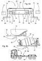
- shows one installation kit according to the inveention, and
- Figure 4b
- shows one transport vehicle equipped with arrangements according to the invention, with two alternative superstructures.
-
Figures 1a - c show transport vehicles that are, as such, conventional, which in this case are trucks. The trucks shown have different types of chassis, with different types of superstructure on them. In other words, each truck is designed and manufactured for a specific tasks. Precisely due to the superstructures, the frames of the trucks are subject to torsion stress. Thus, auxiliary frames, which extend to nearly the entire length of the truck, have been installed on top of the frames. The frame and the auxiliary frame together then form a functional totality, which is sufficiently stiff against loadings, especially bending. InFigures 1a - c , the auxiliary frames 10 are shown by diagonal shading. The truck inFigure 1a is equipped with a concrete container, the auxiliary frame being supported on theframe 11 by eightattachments 12 on each side of the frame. InFigure 1b , theauxiliary frame 10 of the concrete mixer is supported on the truck'sframe 11 by thirteenattachments 12 on each side of the frame.Figure 1c shows a hook-skip device, theauxiliary frame 10 of which is supported on the truck'sframe 11 by fiveattachments 12 on each side of the frame. All the vehicles shown are adapted for a single function. Different types of simple skips and containers can be attached only to the hook-skip device. - As such, the aforementioned attachments can be replaced with a known conical-pin arrangement, in which the openings arranged in the superstructure's auxiliary frame are adapted onto relatively large conical pins arranged vertically permanently in the frame of the transport vehicle. Impractical and labourious wedges must then be used. In addition, the conical pins require alterations to the vehicle's frame. In addition, the conical pins require alteration of the vehicle's frame. The support structures then made may even limit the use of certain types of superstructure. In addition, the wedges may remain under the superstructure, in which case it will be impossible to remove in field conditions. On the other hand, a certain type of superstructure can prevent the use of a conical-pin arrangement entirely. In other words, the conical-pin arrangement is unsuitable for most superstructures.
- Thus, the invention relates to an arrangement in the frame of a transport vehicle. Generally, the arrangement includes an
auxiliary frame 10 for asuperstructure 13, which auxiliary frame is fitted on top of theframe 11 of the transport vehicle. In other words, the auxiliary frame is directly, or nearly directly on the upper surface of the frame beam. In addition, the arrangement includes a plurality of lockingelements 14 for fastening theauxiliary frame 10 detachably to theframe 11. Thus, by releasing the locking elements, the superstructure can be detached from the transport vehicle. The lockingelement 14 is formed of a lockingpin 15 supported on theframe 11, a lockingcounter-piece 17 corresponding to which being arranged in theauxiliary frame 10. In addition, a lockingcounter-piece 17, corresponding to the lockingpin 15 is arranged in theauxiliary frame 10. The arrangement also includes anoperating element 16 for moving the lockingpin 15. Thanks to the operating element, the locking pin can be operated without tools. In addition, the locking pin is attached by a support structure to form part of the frame, so that it is impossible to detach. The locking pin is thus supported on the frame, so that the forces and loadings are transmitted from the auxiliary frame through the locking pin directly to the frame, and vice versa. In this way, detrimental bending moments are avoided and mainly only shear forces act on the locking pin. Asupport collar 19, which is attached by asupport structure 20 to theframe 11, is arranged to support the lockingpin 15. The operatingelement 16 too is supported on thesupport structure 20. In the arrangement each lockingelement 14 consists of a lockingpin 15. In addition, the lockingcounter-piece 17 consists of a sleeve attached to theauxiliary frame 10, and which extends through asteel beam 37 belonging to theauxiliary frame 10. Further, the height of thesupport structure 20 is less than that of theauxiliary frame 10. In practice, the durability of the fastening achieved by means of the locking pin and the sleeve extending through the auxiliary frame corresponds to a bolted joint according to the prior art. The operating element too is saved from excess loading and is easy to fasten to the frame. Above all, the locking created is reliable, but can be easily and rapidly locked and opened nearly an infinite number of times. Thus, the superstructure can always be changed as required, without tools, quickly and easily. The locking pin, together with the support collar and sleeve, forms a bearing, which permits the bending of the frame and auxiliary frame, without breaking. It has been observed in tests, that the fastenings achieved using the arrangement according to the invention withstand, for example, the repeated tipping of a gravel skip, without breaking. In addition, to theauxiliary frame 10 belongs asteel beam 37 through which thesleeve 21 extends and which is arranged aligned right to the top of theframe beam 18. Also the height of thesupport structure 20 is less than the height of thesteel beam 37 while the most of thesupport structure 20 together with operatingelement 16 is arranged above the frame beams 18. -
Figure 2a shows a rear view of the arrangement according to the invention. In a conventional manner, theframe 11 of the transport vehicle consists of two parallel frame beams 18, the distance between which is about 1000 mm. The distance depending on the manufacturer and model of the transport vehicle. Cross-braces and other possible support structures are not shown, for reasons of clarity. In this case, the lockingpin 15 is supported on asupport collar 19 attached to theframe 11, through a support structure 20 (Figure 2b ). The support collar acts as a guide for the locking pin and, in addition, strengthens the structure. Theauxiliary frame 10, to which the locking pins 15 fasten, comes on top of the frame beams. Sturdy locking is then easily achieved. -
Figure 2b shows the construction according to the invention in greater detail. Thesupport collar 19 is attached to the frame by asupport structure 20, the height of which is, according to the invention, less than that of theauxiliary frame 10. Thus, the support structure fits inside the auxiliary frame, without in any way hindering, never mind increasing the height of the frame structure. In addition, the lockingcounter-piece 17 thus consists of asleeve 21, which extends through thesteel beam 37 belonging to theauxiliary frame 10. The locking pin then has a precisely-shaped locking counter-piece. In addition, the sleeve can be attached securely to the auxiliary frame, which is also mainly formed of steel profiles, such as rectangular profiles. In this case, thesleeve 21 is welded at both ends to thesteel beam 37, on both walls of which the sleeve is thus supported. In addition, the sleeve extending fully through the steel beam is open at both ends, so that possible dirt can escape from the sleeve. The internal dimension of the sleeve is slightly greater than the external dimension of the locking pin. The coupling will then be reliable even in demanding conditions, without the locking pin jamming in the sleeve. Grease nipples, by means of which lubrication can be placed between the opposing surfaces, are preferably used in connection with the sleeve and/or support collar. The grease will also help to eliminate play. Play can also be avoided by using a locking pin with a conical head. By also arranging the sleeve to narrow, a self-aligning and tightening locking will be achieved, which is entirely play-free. - The operating element and locking pin can be fitted to each other in different ways. For example, the locking pin can be fitted as an extension of a short hydraulic cylinder and the hydraulic cylinder can be attached to the frame of the transport vehicle by means of the support structure. In the embodiments shown, two opposing locking pins 15 are connected to a
single operating element 16, which is arranged to float in a support structure 20 (Figures 2a and4a ). During locking, the hydraulic cylinder then lengthens, pushing the locking pins farther from each other. Once one or other of the locking pins is home, the hydraulic cylinder installed in a floating manner continues to extend, until the other locking pin is home. Correspondingly, when opening the coupling, thehydraulic cylinder 22 first of all pulls the more detached locking pin out of the sleeve. Once thelimiter pin 23 reaches the end of theslot 24, the other locking pin too begins to move out of its sleeve. In addition, the limiter pin, which is moveably supported in the slot, prevents the hydraulic cylinder from rotating, thus preventing the hydraulic hoses from breaking. InFigure 2a , theslots 24 are formed in asupport plate 25, which is shown here by broken lines. InFigure 3a , thesupport plate 25 is horizontal and the location of the limiter pin is shown by a broken line. - In the embodiment of
Figure 2b , thesupport structure 20 includes atransverse beam 26, which is fastened detachably to theframe 11. Here, thesupport structure 20 is attached to theframe 11 by a bolted joint 38. Thus, the attachment is made sturdy and the support structure can be detached and attached again at another location, or to another transport vehicle. The question is of a very compact construction, which can be located in connection with different types of frame. Here, thetransverse beam 26 is formed by a plate structure, in which thesupport collar 19 is attached to anend plate 27, to the upper part of which is welded aplate 28 extending to a second corresponding end plate. Theplate 28, which is about 200-mm wide, in addition protects the operating element from loose objects falling from above. Anangle iron 29, by means of which the transverse beam is attached to the frame by several fasteners, such as bolts equipped with nuts, is welded to the lower part of theend plate 27. The location of the locking pin too can be adjusted to correspond to the installation height of the sleeves of the auxiliary frame, by altering the installation location of the transverse beam. Thanks to the structure supporting the support collar and transverse beam, loadings are transferred from the auxiliary frame to the frame, without loading the operating element. InFigure 3a , thesupport structure 20 includes alongitudinal beam 30, through which thesupport collar 19 extends. In this case, the support structure is stiff enough for the transverse beam to be omitted. The structure is further reinforced by aninstallation plate 31, which extends from between theauxiliary frame 10 andframe 11 to outside of theframe 11. In addition, theinstallation plate 31 is welded at both sides to theframe 11. Theauxiliary frame 10 is then raised about 10 - 20-mm higher than in the embodiment ofFigure 2b . In other ways, the operation of the embodiment corresponds to that of the embodiment ofFigure 2b . - The dimensioning of the sleeves, support collars, locking pins, operating elements, and support structures can vary in different embodiments. In a tested embodiment, a locking-pin diameter of 50 mm was used. Preferably, in the open position, the end of the locking
pin 15 remains inside thesupport collar 19, as shown inFigures 2b and3a . In the closed position, the lockingpin 15 protrudes deeply into thesleeve 21, which is shown by the broken-line locking pin outline inFigures 2b and3a . The grease nipples are not shown. One support structure according to the invention, together with the operating devices and locking pins, weighs only about 40 kilograms. In theend plate 27 andlongitudinal beams 30, there is a sloping part, guided by which theauxiliary frame 10 settles into the correct location, even though the vehicle might not be completely correctly aligned. In the longitudinal direction, alignment is made by arranging an end stop in the vehicle, against which the superstructure is pushed by moving the vehicle. - In the transport vehicle shown, there is a superstructure auxiliary frame fitted on top of the frame. The auxiliary frame is detachably fastened to be frame by a plurality of locking elements. Here each locking element is formed of a locking pin and the locking counter-piece is formed of a sleeve attached to the auxiliary frame, which extends through the steel beam belonging to the auxiliary frame, and the height of the support structure is less than that of the auxiliary frame. Thus, one or other of the arrangements described above, or a variation of them, is preferably used in the transport vehicle.
- The superstructure can be detached in different ways. In connection with the arrangement according to the invention, the air suspension of the vehicle, or, as such known, lifting cylinders attached to the frame can be applied. For example, using air suspension, the height of the vehicle can be changed by about 200 mm. In the superstructure, there can also be telescopic support legs. Irrespective of the manner of lifting, the locking is opened and the superstructure on top of the vehicle is raised to its upper position. After this, support legs or similar are placed under the superstructure and the vehicle is moved away from under the superstructure.
- Next, the transport vehicle is moved under the desired superstructure, which is supported separately from the chassis. In the vehicle, there is preferably an end stop, which the superstructure auxiliary frame strikes. The auxiliary frame and frame will then be in the correct longitudinal position. By raising the vehicle and/or lowering the superstructure, the auxiliary frame and the frame are brought opposite to each other. The sloping parts of the
support structure 20 guide theauxiliary frame 10 laterally, when theauxiliary frame 10 will automatically take up its correct position. After this, the operating elements are used to move the locking pins into the sleeves, after which the locking is ready. In practice, by using the arrangement according to the invention, the superstructure can be replaced with another in a few minutes. - In principle, the arrangement could be standardized, in which case different transport vehicles and superstructures could be mutually cross-coupled. However, there is so great variation in chassis and superstructures that the greatest advantage will be gained by equipping a vehicle with several alternative superstructures, the locking counter-pieces of which are arranged according to the locking pins. In other words, the arrangement is vehicle-make-specific, and is based on the frame width, whereas known skip devices are based on the width of the superstructure. In other words, the arrangement is arranged for a single piece of transport equipment. Of course, in practice, it is possible to use, for example, ten trucks, in all of which is the same type of arrangement. In that case, any auxiliary frame, dimensioned and equipped according to the arrangement, belonging to the transport equipment, can be fastened to any of the trucks. In particular, there could be several simple skips, but only one or two concrete mixers, for example. What is important is the high utilization of the trucks and their flexible adaptability to correspond to the transport needs at any time.
- The number of locking pins depends largely on the size of the transport vehicle, there being generally one or two locking pins to each metre of length of the auxiliary frame. In embodiments described, this means one to two pairs of locking pins to each metre of length. The operating
elements 16 ofFigure 3b are permanently installed in the frame (not shown). A compressed-medium union 32 is led to the operating elements and this is controlled using suitable valves, for example, from the cab. The operatingelements 16 also preferably include sensors, which detect the open and closed positions of the locking pins. Thecables 33 of the sensors are connected and their information is displayed, for example, on the dashboard in the cab. Thus, the driver can work the operating elements from the cab and always be sure when the locking is open and when it is closed. The control means can also be elsewhere in the vehicle and can also be wireless devices, like a remote control. - Using only the locking pins, a sturdy coupling between the frame and the auxiliary frame is achieved. In practice, there are numerous operations in superstructures, such as tipping, that demand, for example, hydraulic pressure. According to the invention, the
necessary unions 34 for operations are arranged in theauxiliary frame 10. In addition, the unions are connected to quick-release connectors 35, thehoses 36 corresponding to which are fitted to the vehicle. Then, despite the superstructure, the operations can be performed while still permitting a rapid change. For example, known hook-skip equipment is completely incompatible with device totalities, as it lacks the necessary connections. - If the auxiliary frame of
Figure 3b was that of a skip, the two thin hoses could be for automatic lubrication of the pivots. Correspondingly, the two thick hoses would be for the tipping cylinder and the tailgate cylinders. In other words, the tipping cylinder would be part of the auxiliary frame. In that case, when the tipping skip was removed, only the arrangements would remain in the transport vehicle. Correspondingly, in a concrete mixer, one hose would be for the hydraulic motor rotating the mixer, the second hose being for the lifting cylinder of the unloading chute. In general, a single connection on a vehicle can be used for different operations in different superstructures, which are arranged as part of each superstructure. Naturally, the number of connections is selected according to the superstructures required. In any event, using even simple vehicle connections it is possible to use even very diverse operations. The connections can also include, for example, compressed-air, electrical, and/or control connections. As well as, or instead of hydraulic operating devices, it is possible to use, for example, pneumatic cylinders or linear motors. In addition, instead of cylindrical or conical locking pins, pins of other shapes can be used. At the same time, the shape of the fastening counter-piece will change. InFigures 2b and3a , the auxiliary frame is formed from two steel beams 37. Possible diagonal and transverse support are not shown. InFigure 3b , the steel beams of theauxiliary frame 10 are C-beams, which are connected by transverse steel profiles. At the locations of the arrangements, additional plates would be added to the auxiliary frame in question, which would be welded between the flanges of the C-profiles. The sleeve could then be welded at both ends to the auxiliary frame. -
Figure 4a shows one installation kit according to the invention, which is ready to be attached to the transport vehicle. In addition to the installation kit, hydraulic hoses and control valves, for example, will be required, the number of which will vary with each case. In the installation kit, all thelocking elements 14 consist of locking pins 15. In addition, the installation kit also includes lockingcounter-pieces 17, corresponding to the locking pins 15, to be arranged in the auxiliary frame. In the existing auxiliary frame, a opening is first machined for the locking counter-pieces, each lockingcounter-piece 17 of which consists of asleeve 21, the length of which is greater than the cross dimension of the steel beam belonging to the future auxiliary frame. In addition, a support structure is selected, the height of which is less than the future auxiliary frame. Thus, the support structure will fit under the auxiliary frame. Thesupport structure 20 preferably includes twosupport collars 19 arranged opposite to each other, inside each of which alocking pin 15 is arranged and, in addition, an operatingelement 16 is arranged between the locking pins 15, concentrically with the locking pins 15. This makes the structure compact while no excess stresses act of the operating element supported on the support structure and the operating element can be supported in a floating manner. -
Figure 4b shows one transport vehicle, in which there is an arrangement according to the invention. Six support structure with an operating element are attached to theframe 18. In the vehicle, there are also the requisite quick-release connectors 35 andconnections 36. In the two superstructures according to the invention there are corresponding quick-release connectors 35 andunions 34. Thus, in the example, a concrete mixer can be replaced in a few minutes with a concrete container by disconnecting the quick-release connectors, changing the superstructures with the aid of the arrangement, and reconnecting the quick-release connectors. Only a sufficient number of installation kits according to the invention are required for the basic vehicle, and corresponding sleeves in the auxiliary frame for the superstructure, as well as suitable connections and unions with quick-release connectors. After installation, the totality is always available and can be freely adapted. Once the superstructure has been removed, only a so-called zero truck remains, in which there is no excess mass. In other words, the maximum payload is always available. For example, a possible loader can be attached to the auxiliary frame of a piece-goods platform. - The arrangement according to the invention permits the full utilization of a transport vehicle, such as a truck, for example, as a gravel truck, a timber truck, a skip truck, a piece-goods truck, as well as a concrete truck, as required. Thus, a single truck can be used for all purposes, which was previously impossible. In addition, increases in height and weight are avoided, while the changing of the superstructure is nevertheless rapid. In addition to a truck, the arrangement can also be used in trailers. By means of the arrangement, it is even possible to attach a fifth wheel to a semi-trailer tractor. It is then possible, for example, to attach a fifth wheel in place of a gravel box.
Claims (13)
- Arrangement in the frame of a transport vehicle, which arrangement includes- an auxiliary frame (10) for a superstructure (13), which is fitted on top of the frame (11) of the transport vehicle, which frame (11) includes frame beams (18),- several locking elements (14) for fastening the auxiliary frame (10) detachably to the frame (11), and each looking element (14) formed of a loocking pin (15), which is supported moveably on the frame (11),- a locking counter-piece (17) corresponding to the locking pin (15), arranged in the auxiliary frame (10), which locking counter-piece (17) is formed by a sleeve (21) extending through the auxiliary frame (10),- an operating element (16) for moving the locking pin (15), and- a support collar (19) arranged to support the locking pin (15), which is attached to the frame (11) by a support structure (20), and the operating element (16) is supported on the support structure (20),characterized in that to the auxiliary frame (10) belongs a steel beam (37) through which the sleeve (21) extends and which is arranged aligned right to the top of the frame beam (18), and the height of the support structure (20) is less than the height of the steel beam (37) while the most of the support structure (20) together with operating element (16) is arranged above the frame beams (18).
- Arrangement according to Claim 1, characterized in that the support structure (20) is detachably attached to the frame (11).
- Arrangement according to Claim 2, characterized in that the support structure (20) is attached to the frame (11) by bolted joints (38).
- Arrangement according to any of Claims 1 - 3, characterized in that the end of the locking pin (15) is conical.
- Arrangement according to any of Claims 1 - 4, characterized in that two locking pins (15) are joined to a single operating element (16), which is arranged to float in a support structure (20).
- Arrangement according to any of Claims 1 - 5, characterized in that the support structure (20) includes a longitudinal beam (30), through which the support collar (19) extends.
- Arrangement according to any of claims 1 - 5, characterized in that the support structure (20) includes a transverse beam (26), which is fastened detachably to the frame (11).
- Arrangement according to any of claims 1 - 7, characterized in that there are one or two locking pins (15) to each metre of length of the auxiliary frame (10).
- Arrangement according to any of Claims 1 - 8, characterized in that the transport vehicle is equipped with a plurality of alternative superstructures (13), in which the sleeves (21) are arranged according to the locking pins (15).
- Arrangement any of Claims 1 - 9, characterized in that the auxiliary frame (10) includes the requisite unions (34) for the operations of the superstructure (13), and the connections (34) are, in addition, connected to quick-release connectors (35), connections (36) corresponding to which are fitted to the transport vehicle.
- Arrangement according to Claim 10, characterized in that the connections (36) include hydraulic, compressed-air, electrical, and/or control connections.
- Installation kit for creating an arrangement in the frame of a transport vehicle, which installation kit includes- a plurality of locking elements (14) for fastening the auxiliary frame (10), belonging to the transport vehicle, detachably to the frame (11), belonging to the transport vehicle, and all the locking elements (14) consist of locking pins (15),- support collars (19) arranged to support the locking pins (15),- locking counter-pieces (17), corresponding to the locking pins (15), to be arranged in the auxiliary frame (10), and each locking counter-piece (17) consists of a sleeve (21), and- an operating element (16) for moving the locking pin,the installation kit further includes a support structure (20) to be attached to the frame (11) including frame beams (18), to which the support collars (19) are attached, and on which the operating element (16) is supported, characterized in that the length of the sleeve (21) is greater than the cross dimension of the steel beam (37) belonging to the auxiliary frame (10), and the height of the support structure (20) is less than the height of the steel beam (37), which is arranged to positioned aligned right to the top of the frame beam (18), while the most of the support structure (20) together with operating element (16) is arranged to be positioned above the frame beams (18).
- Installation kit according to Claim 12, characterized in that the support structure (20) includes two support collars (19) arranged opposing each other, inside each of which a locking pin (15) is fitted, and an operating element (16) is arranged between the locking pins (15), concentrically with the locking pins (15).
Priority Applications (2)
| Application Number | Priority Date | Filing Date | Title |
|---|---|---|---|
| PL11150952T PL2345556T3 (en) | 2010-01-15 | 2011-01-14 | Transport vehicle with a locking device |
| SI201130631T SI2345556T1 (en) | 2010-01-15 | 2011-01-14 | Transport vehicle with a locking device |
Applications Claiming Priority (1)
| Application Number | Priority Date | Filing Date | Title |
|---|---|---|---|
| FI20105028A FI20105028L (en) | 2010-01-15 | 2010-01-15 | ARRANGEMENT IN THE BODY OF THE MEANS OF TRANSPORT AND THE MEANS OF TRANSPORT |
Publications (2)
| Publication Number | Publication Date |
|---|---|
| EP2345556A1 EP2345556A1 (en) | 2011-07-20 |
| EP2345556B1 true EP2345556B1 (en) | 2015-07-29 |
Family
ID=41620866
Family Applications (1)
| Application Number | Title | Priority Date | Filing Date |
|---|---|---|---|
| EP11150952.7A Active EP2345556B1 (en) | 2010-01-15 | 2011-01-14 | Transport vehicle with a locking device |
Country Status (9)
| Country | Link |
|---|---|
| EP (1) | EP2345556B1 (en) |
| DK (1) | DK2345556T3 (en) |
| ES (1) | ES2550475T3 (en) |
| FI (1) | FI20105028L (en) |
| HU (1) | HUE025933T2 (en) |
| PL (1) | PL2345556T3 (en) |
| PT (1) | PT2345556E (en) |
| RS (1) | RS54283B1 (en) |
| SI (1) | SI2345556T1 (en) |
Families Citing this family (3)
| Publication number | Priority date | Publication date | Assignee | Title |
|---|---|---|---|---|
| CN102826132B (en) * | 2012-09-13 | 2015-04-15 | 中联重科股份有限公司 | Fastening mechanism of split car body and guardrail cleaning vehicle |
| DE102020117247A1 (en) | 2020-06-30 | 2021-12-30 | Probst Gmbh | Swap body for a chassis |
| CN115892255A (en) * | 2022-08-30 | 2023-04-04 | 广西玉柴专用汽车有限公司 | A locking sensor |
Family Cites Families (6)
| Publication number | Priority date | Publication date | Assignee | Title |
|---|---|---|---|---|
| SE466841B (en) * | 1990-02-13 | 1992-04-13 | Laxo Mekan Ab | BUILDING SYSTEM FOR TRUCKS |
| US5362184A (en) * | 1993-06-15 | 1994-11-08 | Hull Harold L | Lock device for garbage truck container |
| CA2139697A1 (en) * | 1995-01-06 | 1996-07-07 | Donald Douglas Gordon Glen | System and apparatus for converting a railcar or truck trailer to multiple uses |
| US5829946A (en) | 1995-01-24 | 1998-11-03 | Mcneilus Truck And Manufacturing, Inc. | Detachable truck body and handling mechanism |
| SE0100738D0 (en) * | 2001-03-06 | 2001-03-06 | Laxo Mekan Ab | Modified bodywork system for trucks |
| US7866934B2 (en) * | 2007-08-16 | 2011-01-11 | Petersen Industries, Inc. | Apparatus and method for removably attaching a loading device to a vehicle |
-
2010
- 2010-01-15 FI FI20105028A patent/FI20105028L/en not_active IP Right Cessation
-
2011
- 2011-01-14 PT PT111509527T patent/PT2345556E/en unknown
- 2011-01-14 RS RS20150652A patent/RS54283B1/en unknown
- 2011-01-14 PL PL11150952T patent/PL2345556T3/en unknown
- 2011-01-14 SI SI201130631T patent/SI2345556T1/en unknown
- 2011-01-14 ES ES11150952.7T patent/ES2550475T3/en active Active
- 2011-01-14 DK DK11150952.7T patent/DK2345556T3/en active
- 2011-01-14 HU HUE11150952A patent/HUE025933T2/en unknown
- 2011-01-14 EP EP11150952.7A patent/EP2345556B1/en active Active
Also Published As
| Publication number | Publication date |
|---|---|
| PL2345556T3 (en) | 2015-12-31 |
| FI20105028A0 (en) | 2010-01-15 |
| PT2345556E (en) | 2015-11-03 |
| FI20105028A7 (en) | 2011-07-16 |
| FI20105028L (en) | 2011-07-16 |
| DK2345556T3 (en) | 2015-10-19 |
| EP2345556A1 (en) | 2011-07-20 |
| SI2345556T1 (en) | 2015-12-31 |
| HUE025933T2 (en) | 2016-05-30 |
| ES2550475T3 (en) | 2015-11-10 |
| RS54283B1 (en) | 2016-02-29 |
Similar Documents
| Publication | Publication Date | Title |
|---|---|---|
| CN101855106B (en) | Heavy-duty transport modular vehicles especially for ports | |
| EP3144524B1 (en) | A handling system for a wind turbine nacelle, methods for transport and vertical displacement of a wind turbine nacelle | |
| DE69431516T2 (en) | VEHICLE WITH A U-SHAPED FRAME | |
| US20150008296A1 (en) | Stand for machine components | |
| US4456414A (en) | Quick coupling apparatus for interchangeable truck bodies | |
| SU1012793A3 (en) | Versatile vehicle | |
| WO2020001844A1 (en) | Device for the installation and dismounting of aircraft engines | |
| DK2345556T3 (en) | Transport vehicle with a locking device | |
| US20230114428A1 (en) | Hoist for vehicle with interchangeable body | |
| DE3445741C2 (en) | Train composed of individual vehicles for road and rail traffic | |
| DE19728822B4 (en) | Cultivation trailing suspension | |
| EP1170199B1 (en) | Combination semi-trailer | |
| US4697819A (en) | Removable drawbar for trailers | |
| SE466841B (en) | BUILDING SYSTEM FOR TRUCKS | |
| DE102024125301B3 (en) | Commercial vehicle with modular battery box | |
| US12600184B1 (en) | Modular multi-height hitch attachment system for skid steer equipment | |
| CN209667105U (en) | A kind of mine vehicle connects vehicle device | |
| CN223346253U (en) | Electric rail truck scale | |
| DE102010047088A1 (en) | Semitrailer device for a semitrailer | |
| DE19508281A1 (en) | Crane-lorry combination with independent crane mounting | |
| SE434933B (en) | DEVICE FOR TRUCKS WITH A HIGHLIGHTS AND SUBSTANTABLE LIFT FRAME CONDUCTED WITH THE CAR'S LONG-LONG FRAME BALLS DEVICE ON TRUCKS WITH A HIGHLIGHTS AND SUBSTANTLY LIFTING FRAME WITH THE CAR'S LONG-LONG FRAMES | |
| EP4709635A1 (en) | Cab tilting arrangement and vehicle and assembly | |
| US20020092708A1 (en) | Quick coupler system | |
| RU2004112994A (en) | CRANE MANIPULATOR | |
| Bellows et al. | Design, Fabrication and Field Testing of Remotely Operated Longwall Head/Tail Supports |
Legal Events
| Date | Code | Title | Description |
|---|---|---|---|
| PUAI | Public reference made under article 153(3) epc to a published international application that has entered the european phase |
Free format text: ORIGINAL CODE: 0009012 |
|
| AK | Designated contracting states |
Kind code of ref document: A1 Designated state(s): AL AT BE BG CH CY CZ DE DK EE ES FI FR GB GR HR HU IE IS IT LI LT LU LV MC MK MT NL NO PL PT RO RS SE SI SK SM TR |
|
| AX | Request for extension of the european patent |
Extension state: BA ME |
|
| 17P | Request for examination filed |
Effective date: 20120119 |
|
| 17Q | First examination report despatched |
Effective date: 20120323 |
|
| GRAP | Despatch of communication of intention to grant a patent |
Free format text: ORIGINAL CODE: EPIDOSNIGR1 |
|
| INTG | Intention to grant announced |
Effective date: 20150224 |
|
| GRAS | Grant fee paid |
Free format text: ORIGINAL CODE: EPIDOSNIGR3 |
|
| GRAA | (expected) grant |
Free format text: ORIGINAL CODE: 0009210 |
|
| AK | Designated contracting states |
Kind code of ref document: B1 Designated state(s): AL AT BE BG CH CY CZ DE DK EE ES FI FR GB GR HR HU IE IS IT LI LT LU LV MC MK MT NL NO PL PT RO RS SE SI SK SM TR |
|
| REG | Reference to a national code |
Ref country code: GB Ref legal event code: FG4D |
|
| REG | Reference to a national code |
Ref country code: CH Ref legal event code: EP |
|
| REG | Reference to a national code |
Ref country code: AT Ref legal event code: REF Ref document number: 738978 Country of ref document: AT Kind code of ref document: T Effective date: 20150815 |
|
| REG | Reference to a national code |
Ref country code: IE Ref legal event code: FG4D |
|
| REG | Reference to a national code |
Ref country code: DE Ref legal event code: R096 Ref document number: 602011018146 Country of ref document: DE |
|
| REG | Reference to a national code |
Ref country code: CH Ref legal event code: NV Representative=s name: FIAMMENGHI-FIAMMENGHI, CH |
|
| REG | Reference to a national code |
Ref country code: DK Ref legal event code: T3 Effective date: 20151013 |
|
| REG | Reference to a national code |
Ref country code: SE Ref legal event code: TRGR |
|
| REG | Reference to a national code |
Ref country code: PT Ref legal event code: SC4A Free format text: AVAILABILITY OF NATIONAL TRANSLATION Effective date: 20151016 |
|
| REG | Reference to a national code |
Ref country code: ES Ref legal event code: FG2A Ref document number: 2550475 Country of ref document: ES Kind code of ref document: T3 Effective date: 20151110 |
|
| REG | Reference to a national code |
Ref country code: NL Ref legal event code: FP |
|
| REG | Reference to a national code |
Ref country code: EE Ref legal event code: FG4A Ref document number: E011122 Country of ref document: EE Effective date: 20151026 |
|
| REG | Reference to a national code |
Ref country code: NO Ref legal event code: T2 Effective date: 20150729 |
|
| REG | Reference to a national code |
Ref country code: PL Ref legal event code: T3 |
|
| REG | Reference to a national code |
Ref country code: FR Ref legal event code: PLFP Year of fee payment: 6 |
|
| PG25 | Lapsed in a contracting state [announced via postgrant information from national office to epo] |
Ref country code: GR Free format text: LAPSE BECAUSE OF FAILURE TO SUBMIT A TRANSLATION OF THE DESCRIPTION OR TO PAY THE FEE WITHIN THE PRESCRIBED TIME-LIMIT Effective date: 20151030 |
|
| PG25 | Lapsed in a contracting state [announced via postgrant information from national office to epo] |
Ref country code: HR Free format text: LAPSE BECAUSE OF FAILURE TO SUBMIT A TRANSLATION OF THE DESCRIPTION OR TO PAY THE FEE WITHIN THE PRESCRIBED TIME-LIMIT Effective date: 20150729 |
|
| REG | Reference to a national code |
Ref country code: SK Ref legal event code: T3 Ref document number: E 19629 Country of ref document: SK |
|
| REG | Reference to a national code |
Ref country code: DE Ref legal event code: R097 Ref document number: 602011018146 Country of ref document: DE |
|
| REG | Reference to a national code |
Ref country code: HU Ref legal event code: AG4A Ref document number: E025933 Country of ref document: HU |
|
| PG25 | Lapsed in a contracting state [announced via postgrant information from national office to epo] |
Ref country code: RO Free format text: LAPSE BECAUSE OF FAILURE TO SUBMIT A TRANSLATION OF THE DESCRIPTION OR TO PAY THE FEE WITHIN THE PRESCRIBED TIME-LIMIT Effective date: 20150729 |
|
| PLBE | No opposition filed within time limit |
Free format text: ORIGINAL CODE: 0009261 |
|
| STAA | Information on the status of an ep patent application or granted ep patent |
Free format text: STATUS: NO OPPOSITION FILED WITHIN TIME LIMIT |
|
| 26N | No opposition filed |
Effective date: 20160502 |
|
| PG25 | Lapsed in a contracting state [announced via postgrant information from national office to epo] |
Ref country code: LU Free format text: LAPSE BECAUSE OF FAILURE TO SUBMIT A TRANSLATION OF THE DESCRIPTION OR TO PAY THE FEE WITHIN THE PRESCRIBED TIME-LIMIT Effective date: 20160114 |
|
| PG25 | Lapsed in a contracting state [announced via postgrant information from national office to epo] |
Ref country code: MC Free format text: LAPSE BECAUSE OF FAILURE TO SUBMIT A TRANSLATION OF THE DESCRIPTION OR TO PAY THE FEE WITHIN THE PRESCRIBED TIME-LIMIT Effective date: 20150729 |
|
| REG | Reference to a national code |
Ref country code: FR Ref legal event code: PLFP Year of fee payment: 7 |
|
| PGFP | Annual fee paid to national office [announced via postgrant information from national office to epo] |
Ref country code: IS Payment date: 20161212 Year of fee payment: 7 |
|
| REG | Reference to a national code |
Ref country code: AT Ref legal event code: UEP Ref document number: 738978 Country of ref document: AT Kind code of ref document: T Effective date: 20150729 |
|
| PG25 | Lapsed in a contracting state [announced via postgrant information from national office to epo] |
Ref country code: MT Free format text: LAPSE BECAUSE OF FAILURE TO SUBMIT A TRANSLATION OF THE DESCRIPTION OR TO PAY THE FEE WITHIN THE PRESCRIBED TIME-LIMIT Effective date: 20150729 |
|
| REG | Reference to a national code |
Ref country code: FR Ref legal event code: PLFP Year of fee payment: 8 |
|
| PG25 | Lapsed in a contracting state [announced via postgrant information from national office to epo] |
Ref country code: CY Free format text: LAPSE BECAUSE OF FAILURE TO SUBMIT A TRANSLATION OF THE DESCRIPTION OR TO PAY THE FEE WITHIN THE PRESCRIBED TIME-LIMIT Effective date: 20150729 Ref country code: SM Free format text: LAPSE BECAUSE OF FAILURE TO SUBMIT A TRANSLATION OF THE DESCRIPTION OR TO PAY THE FEE WITHIN THE PRESCRIBED TIME-LIMIT Effective date: 20150729 |
|
| PG25 | Lapsed in a contracting state [announced via postgrant information from national office to epo] |
Ref country code: MT Free format text: LAPSE BECAUSE OF FAILURE TO SUBMIT A TRANSLATION OF THE DESCRIPTION OR TO PAY THE FEE WITHIN THE PRESCRIBED TIME-LIMIT Effective date: 20160131 Ref country code: MK Free format text: LAPSE BECAUSE OF FAILURE TO SUBMIT A TRANSLATION OF THE DESCRIPTION OR TO PAY THE FEE WITHIN THE PRESCRIBED TIME-LIMIT Effective date: 20150729 |
|
| PG25 | Lapsed in a contracting state [announced via postgrant information from national office to epo] |
Ref country code: BG Free format text: LAPSE BECAUSE OF FAILURE TO SUBMIT A TRANSLATION OF THE DESCRIPTION OR TO PAY THE FEE WITHIN THE PRESCRIBED TIME-LIMIT Effective date: 20150729 |
|
| PG25 | Lapsed in a contracting state [announced via postgrant information from national office to epo] |
Ref country code: AL Free format text: LAPSE BECAUSE OF FAILURE TO SUBMIT A TRANSLATION OF THE DESCRIPTION OR TO PAY THE FEE WITHIN THE PRESCRIBED TIME-LIMIT Effective date: 20150729 |
|
| PG25 | Lapsed in a contracting state [announced via postgrant information from national office to epo] |
Ref country code: IS Free format text: LAPSE BECAUSE OF FAILURE TO SUBMIT A TRANSLATION OF THE DESCRIPTION OR TO PAY THE FEE WITHIN THE PRESCRIBED TIME-LIMIT Effective date: 20180801 |
|
| PGFP | Annual fee paid to national office [announced via postgrant information from national office to epo] |
Ref country code: PT Payment date: 20181218 Year of fee payment: 9 |
|
| PGFP | Annual fee paid to national office [announced via postgrant information from national office to epo] |
Ref country code: ES Payment date: 20190226 Year of fee payment: 9 Ref country code: IT Payment date: 20190124 Year of fee payment: 9 Ref country code: CZ Payment date: 20190114 Year of fee payment: 9 Ref country code: IE Payment date: 20190122 Year of fee payment: 9 |
|
| PGFP | Annual fee paid to national office [announced via postgrant information from national office to epo] |
Ref country code: BE Payment date: 20190121 Year of fee payment: 9 Ref country code: SI Payment date: 20181221 Year of fee payment: 9 |
|
| REG | Reference to a national code |
Ref country code: CH Ref legal event code: PL |
|
| REG | Reference to a national code |
Ref country code: AT Ref legal event code: MM01 Ref document number: 738978 Country of ref document: AT Kind code of ref document: T Effective date: 20200114 |
|
| GBPC | Gb: european patent ceased through non-payment of renewal fee |
Effective date: 20200114 |
|
| REG | Reference to a national code |
Ref country code: SK Ref legal event code: MM4A Ref document number: E 19629 Country of ref document: SK Effective date: 20200114 |
|
| REG | Reference to a national code |
Ref country code: BE Ref legal event code: MM Effective date: 20200131 |
|
| PG25 | Lapsed in a contracting state [announced via postgrant information from national office to epo] |
Ref country code: SK Free format text: LAPSE BECAUSE OF NON-PAYMENT OF DUE FEES Effective date: 20200114 Ref country code: PT Free format text: LAPSE BECAUSE OF NON-PAYMENT OF DUE FEES Effective date: 20200814 Ref country code: CZ Free format text: LAPSE BECAUSE OF NON-PAYMENT OF DUE FEES Effective date: 20200114 Ref country code: GB Free format text: LAPSE BECAUSE OF NON-PAYMENT OF DUE FEES Effective date: 20200114 |
|
| PG25 | Lapsed in a contracting state [announced via postgrant information from national office to epo] |
Ref country code: LI Free format text: LAPSE BECAUSE OF NON-PAYMENT OF DUE FEES Effective date: 20200131 Ref country code: SI Free format text: LAPSE BECAUSE OF NON-PAYMENT OF DUE FEES Effective date: 20200115 Ref country code: CH Free format text: LAPSE BECAUSE OF NON-PAYMENT OF DUE FEES Effective date: 20200131 Ref country code: HU Free format text: LAPSE BECAUSE OF NON-PAYMENT OF DUE FEES Effective date: 20200115 Ref country code: AT Free format text: LAPSE BECAUSE OF NON-PAYMENT OF DUE FEES Effective date: 20200114 Ref country code: BE Free format text: LAPSE BECAUSE OF NON-PAYMENT OF DUE FEES Effective date: 20200131 |
|
| PG25 | Lapsed in a contracting state [announced via postgrant information from national office to epo] |
Ref country code: IE Free format text: LAPSE BECAUSE OF NON-PAYMENT OF DUE FEES Effective date: 20200114 Ref country code: IT Free format text: LAPSE BECAUSE OF NON-PAYMENT OF DUE FEES Effective date: 20200114 |
|
| REG | Reference to a national code |
Ref country code: DE Ref legal event code: R082 Ref document number: 602011018146 Country of ref document: DE Representative=s name: KILBURN & STRODE LLP, NL |
|
| REG | Reference to a national code |
Ref country code: ES Ref legal event code: FD2A Effective date: 20210603 |
|
| PG25 | Lapsed in a contracting state [announced via postgrant information from national office to epo] |
Ref country code: ES Free format text: LAPSE BECAUSE OF NON-PAYMENT OF DUE FEES Effective date: 20200115 |
|
| REG | Reference to a national code |
Ref country code: EE Ref legal event code: HC1A Ref document number: E011122 Country of ref document: EE |
|
| PG25 | Lapsed in a contracting state [announced via postgrant information from national office to epo] |
Ref country code: PL Free format text: LAPSE BECAUSE OF NON-PAYMENT OF DUE FEES Effective date: 20200114 |
|
| PGFP | Annual fee paid to national office [announced via postgrant information from national office to epo] |
Ref country code: RS Payment date: 20220112 Year of fee payment: 12 |
|
| PG25 | Lapsed in a contracting state [announced via postgrant information from national office to epo] |
Ref country code: TR Free format text: LAPSE BECAUSE OF NON-PAYMENT OF DUE FEES Effective date: 20200114 |
|
| PG25 | Lapsed in a contracting state [announced via postgrant information from national office to epo] |
Ref country code: RS Free format text: LAPSE BECAUSE OF NON-PAYMENT OF DUE FEES Effective date: 20230717 |
|
| PGFP | Annual fee paid to national office [announced via postgrant information from national office to epo] |
Ref country code: NL Payment date: 20250121 Year of fee payment: 15 |
|
| PGFP | Annual fee paid to national office [announced via postgrant information from national office to epo] |
Ref country code: DE Payment date: 20250121 Year of fee payment: 15 |
|
| PGFP | Annual fee paid to national office [announced via postgrant information from national office to epo] |
Ref country code: DK Payment date: 20250124 Year of fee payment: 15 Ref country code: FI Payment date: 20250114 Year of fee payment: 15 Ref country code: LT Payment date: 20250109 Year of fee payment: 15 |
|
| PGFP | Annual fee paid to national office [announced via postgrant information from national office to epo] |
Ref country code: SE Payment date: 20250122 Year of fee payment: 15 |
|
| PGFP | Annual fee paid to national office [announced via postgrant information from national office to epo] |
Ref country code: NO Payment date: 20250124 Year of fee payment: 15 |
|
| PGFP | Annual fee paid to national office [announced via postgrant information from national office to epo] |
Ref country code: LV Payment date: 20250116 Year of fee payment: 15 Ref country code: EE Payment date: 20250116 Year of fee payment: 15 |
|
| PGFP | Annual fee paid to national office [announced via postgrant information from national office to epo] |
Ref country code: FR Payment date: 20250127 Year of fee payment: 15 |