EP2345473A2 - Method for constant concentration evaporation and a device using the same - Google Patents
Method for constant concentration evaporation and a device using the same Download PDFInfo
- Publication number
- EP2345473A2 EP2345473A2 EP11150646A EP11150646A EP2345473A2 EP 2345473 A2 EP2345473 A2 EP 2345473A2 EP 11150646 A EP11150646 A EP 11150646A EP 11150646 A EP11150646 A EP 11150646A EP 2345473 A2 EP2345473 A2 EP 2345473A2
- Authority
- EP
- European Patent Office
- Prior art keywords
- evaporator
- precursor
- heat exchanger
- conduit
- inner casing
- Prior art date
- Legal status (The legal status is an assumption and is not a legal conclusion. Google has not performed a legal analysis and makes no representation as to the accuracy of the status listed.)
- Granted
Links
Images

Classifications
-
- B—PERFORMING OPERATIONS; TRANSPORTING
- B01—PHYSICAL OR CHEMICAL PROCESSES OR APPARATUS IN GENERAL
- B01B—BOILING; BOILING APPARATUS ; EVAPORATION; EVAPORATION APPARATUS
- B01B1/00—Boiling; Boiling apparatus for physical or chemical purposes ; Evaporation in general
- B01B1/005—Evaporation for physical or chemical purposes; Evaporation apparatus therefor, e.g. evaporation of liquids for gas phase reactions
-
- B—PERFORMING OPERATIONS; TRANSPORTING
- B01—PHYSICAL OR CHEMICAL PROCESSES OR APPARATUS IN GENERAL
- B01B—BOILING; BOILING APPARATUS ; EVAPORATION; EVAPORATION APPARATUS
- B01B1/00—Boiling; Boiling apparatus for physical or chemical purposes ; Evaporation in general
- B01B1/06—Preventing bumping
-
- C—CHEMISTRY; METALLURGY
- C23—COATING METALLIC MATERIAL; COATING MATERIAL WITH METALLIC MATERIAL; CHEMICAL SURFACE TREATMENT; DIFFUSION TREATMENT OF METALLIC MATERIAL; COATING BY VACUUM EVAPORATION, BY SPUTTERING, BY ION IMPLANTATION OR BY CHEMICAL VAPOUR DEPOSITION, IN GENERAL; INHIBITING CORROSION OF METALLIC MATERIAL OR INCRUSTATION IN GENERAL
- C23C—COATING METALLIC MATERIAL; COATING MATERIAL WITH METALLIC MATERIAL; SURFACE TREATMENT OF METALLIC MATERIAL BY DIFFUSION INTO THE SURFACE, BY CHEMICAL CONVERSION OR SUBSTITUTION; COATING BY VACUUM EVAPORATION, BY SPUTTERING, BY ION IMPLANTATION OR BY CHEMICAL VAPOUR DEPOSITION, IN GENERAL
- C23C16/00—Chemical coating by decomposition of gaseous compounds, without leaving reaction products of surface material in the coating, i.e. chemical vapour deposition [CVD] processes
- C23C16/22—Chemical coating by decomposition of gaseous compounds, without leaving reaction products of surface material in the coating, i.e. chemical vapour deposition [CVD] processes characterised by the deposition of inorganic material, other than metallic material
- C23C16/30—Deposition of compounds, mixtures or solid solutions, e.g. borides, carbides, nitrides
- C23C16/34—Nitrides
-
- C—CHEMISTRY; METALLURGY
- C23—COATING METALLIC MATERIAL; COATING MATERIAL WITH METALLIC MATERIAL; CHEMICAL SURFACE TREATMENT; DIFFUSION TREATMENT OF METALLIC MATERIAL; COATING BY VACUUM EVAPORATION, BY SPUTTERING, BY ION IMPLANTATION OR BY CHEMICAL VAPOUR DEPOSITION, IN GENERAL; INHIBITING CORROSION OF METALLIC MATERIAL OR INCRUSTATION IN GENERAL
- C23C—COATING METALLIC MATERIAL; COATING MATERIAL WITH METALLIC MATERIAL; SURFACE TREATMENT OF METALLIC MATERIAL BY DIFFUSION INTO THE SURFACE, BY CHEMICAL CONVERSION OR SUBSTITUTION; COATING BY VACUUM EVAPORATION, BY SPUTTERING, BY ION IMPLANTATION OR BY CHEMICAL VAPOUR DEPOSITION, IN GENERAL
- C23C16/00—Chemical coating by decomposition of gaseous compounds, without leaving reaction products of surface material in the coating, i.e. chemical vapour deposition [CVD] processes
- C23C16/44—Chemical coating by decomposition of gaseous compounds, without leaving reaction products of surface material in the coating, i.e. chemical vapour deposition [CVD] processes characterised by the method of coating
- C23C16/4411—Cooling of the reaction chamber walls
-
- C—CHEMISTRY; METALLURGY
- C23—COATING METALLIC MATERIAL; COATING MATERIAL WITH METALLIC MATERIAL; CHEMICAL SURFACE TREATMENT; DIFFUSION TREATMENT OF METALLIC MATERIAL; COATING BY VACUUM EVAPORATION, BY SPUTTERING, BY ION IMPLANTATION OR BY CHEMICAL VAPOUR DEPOSITION, IN GENERAL; INHIBITING CORROSION OF METALLIC MATERIAL OR INCRUSTATION IN GENERAL
- C23C—COATING METALLIC MATERIAL; COATING MATERIAL WITH METALLIC MATERIAL; SURFACE TREATMENT OF METALLIC MATERIAL BY DIFFUSION INTO THE SURFACE, BY CHEMICAL CONVERSION OR SUBSTITUTION; COATING BY VACUUM EVAPORATION, BY SPUTTERING, BY ION IMPLANTATION OR BY CHEMICAL VAPOUR DEPOSITION, IN GENERAL
- C23C16/00—Chemical coating by decomposition of gaseous compounds, without leaving reaction products of surface material in the coating, i.e. chemical vapour deposition [CVD] processes
- C23C16/44—Chemical coating by decomposition of gaseous compounds, without leaving reaction products of surface material in the coating, i.e. chemical vapour deposition [CVD] processes characterised by the method of coating
- C23C16/4412—Details relating to the exhausts, e.g. pumps, filters, scrubbers, particle traps
-
- C—CHEMISTRY; METALLURGY
- C23—COATING METALLIC MATERIAL; COATING MATERIAL WITH METALLIC MATERIAL; CHEMICAL SURFACE TREATMENT; DIFFUSION TREATMENT OF METALLIC MATERIAL; COATING BY VACUUM EVAPORATION, BY SPUTTERING, BY ION IMPLANTATION OR BY CHEMICAL VAPOUR DEPOSITION, IN GENERAL; INHIBITING CORROSION OF METALLIC MATERIAL OR INCRUSTATION IN GENERAL
- C23C—COATING METALLIC MATERIAL; COATING MATERIAL WITH METALLIC MATERIAL; SURFACE TREATMENT OF METALLIC MATERIAL BY DIFFUSION INTO THE SURFACE, BY CHEMICAL CONVERSION OR SUBSTITUTION; COATING BY VACUUM EVAPORATION, BY SPUTTERING, BY ION IMPLANTATION OR BY CHEMICAL VAPOUR DEPOSITION, IN GENERAL
- C23C16/00—Chemical coating by decomposition of gaseous compounds, without leaving reaction products of surface material in the coating, i.e. chemical vapour deposition [CVD] processes
- C23C16/44—Chemical coating by decomposition of gaseous compounds, without leaving reaction products of surface material in the coating, i.e. chemical vapour deposition [CVD] processes characterised by the method of coating
- C23C16/448—Chemical coating by decomposition of gaseous compounds, without leaving reaction products of surface material in the coating, i.e. chemical vapour deposition [CVD] processes characterised by the method of coating characterised by the method used for generating reactive gas streams, e.g. by evaporation or sublimation of precursor materials
- C23C16/4481—Chemical coating by decomposition of gaseous compounds, without leaving reaction products of surface material in the coating, i.e. chemical vapour deposition [CVD] processes characterised by the method of coating characterised by the method used for generating reactive gas streams, e.g. by evaporation or sublimation of precursor materials by evaporation using carrier gas in contact with the source material
- C23C16/4482—Chemical coating by decomposition of gaseous compounds, without leaving reaction products of surface material in the coating, i.e. chemical vapour deposition [CVD] processes characterised by the method of coating characterised by the method used for generating reactive gas streams, e.g. by evaporation or sublimation of precursor materials by evaporation using carrier gas in contact with the source material by bubbling of carrier gas through liquid source material
-
- C—CHEMISTRY; METALLURGY
- C23—COATING METALLIC MATERIAL; COATING MATERIAL WITH METALLIC MATERIAL; CHEMICAL SURFACE TREATMENT; DIFFUSION TREATMENT OF METALLIC MATERIAL; COATING BY VACUUM EVAPORATION, BY SPUTTERING, BY ION IMPLANTATION OR BY CHEMICAL VAPOUR DEPOSITION, IN GENERAL; INHIBITING CORROSION OF METALLIC MATERIAL OR INCRUSTATION IN GENERAL
- C23C—COATING METALLIC MATERIAL; COATING MATERIAL WITH METALLIC MATERIAL; SURFACE TREATMENT OF METALLIC MATERIAL BY DIFFUSION INTO THE SURFACE, BY CHEMICAL CONVERSION OR SUBSTITUTION; COATING BY VACUUM EVAPORATION, BY SPUTTERING, BY ION IMPLANTATION OR BY CHEMICAL VAPOUR DEPOSITION, IN GENERAL
- C23C16/00—Chemical coating by decomposition of gaseous compounds, without leaving reaction products of surface material in the coating, i.e. chemical vapour deposition [CVD] processes
- C23C16/44—Chemical coating by decomposition of gaseous compounds, without leaving reaction products of surface material in the coating, i.e. chemical vapour deposition [CVD] processes characterised by the method of coating
- C23C16/448—Chemical coating by decomposition of gaseous compounds, without leaving reaction products of surface material in the coating, i.e. chemical vapour deposition [CVD] processes characterised by the method of coating characterised by the method used for generating reactive gas streams, e.g. by evaporation or sublimation of precursor materials
- C23C16/4486—Chemical coating by decomposition of gaseous compounds, without leaving reaction products of surface material in the coating, i.e. chemical vapour deposition [CVD] processes characterised by the method of coating characterised by the method used for generating reactive gas streams, e.g. by evaporation or sublimation of precursor materials by producing an aerosol and subsequent evaporation of the droplets or particles
-
- C—CHEMISTRY; METALLURGY
- C23—COATING METALLIC MATERIAL; COATING MATERIAL WITH METALLIC MATERIAL; CHEMICAL SURFACE TREATMENT; DIFFUSION TREATMENT OF METALLIC MATERIAL; COATING BY VACUUM EVAPORATION, BY SPUTTERING, BY ION IMPLANTATION OR BY CHEMICAL VAPOUR DEPOSITION, IN GENERAL; INHIBITING CORROSION OF METALLIC MATERIAL OR INCRUSTATION IN GENERAL
- C23C—COATING METALLIC MATERIAL; COATING MATERIAL WITH METALLIC MATERIAL; SURFACE TREATMENT OF METALLIC MATERIAL BY DIFFUSION INTO THE SURFACE, BY CHEMICAL CONVERSION OR SUBSTITUTION; COATING BY VACUUM EVAPORATION, BY SPUTTERING, BY ION IMPLANTATION OR BY CHEMICAL VAPOUR DEPOSITION, IN GENERAL
- C23C16/00—Chemical coating by decomposition of gaseous compounds, without leaving reaction products of surface material in the coating, i.e. chemical vapour deposition [CVD] processes
- C23C16/44—Chemical coating by decomposition of gaseous compounds, without leaving reaction products of surface material in the coating, i.e. chemical vapour deposition [CVD] processes characterised by the method of coating
- C23C16/455—Chemical coating by decomposition of gaseous compounds, without leaving reaction products of surface material in the coating, i.e. chemical vapour deposition [CVD] processes characterised by the method of coating characterised by the method used for introducing gases into reaction chamber or for modifying gas flows in reaction chamber
- C23C16/45523—Pulsed gas flow or change of composition over time
- C23C16/45525—Atomic layer deposition [ALD]
-
- C—CHEMISTRY; METALLURGY
- C23—COATING METALLIC MATERIAL; COATING MATERIAL WITH METALLIC MATERIAL; CHEMICAL SURFACE TREATMENT; DIFFUSION TREATMENT OF METALLIC MATERIAL; COATING BY VACUUM EVAPORATION, BY SPUTTERING, BY ION IMPLANTATION OR BY CHEMICAL VAPOUR DEPOSITION, IN GENERAL; INHIBITING CORROSION OF METALLIC MATERIAL OR INCRUSTATION IN GENERAL
- C23C—COATING METALLIC MATERIAL; COATING MATERIAL WITH METALLIC MATERIAL; SURFACE TREATMENT OF METALLIC MATERIAL BY DIFFUSION INTO THE SURFACE, BY CHEMICAL CONVERSION OR SUBSTITUTION; COATING BY VACUUM EVAPORATION, BY SPUTTERING, BY ION IMPLANTATION OR BY CHEMICAL VAPOUR DEPOSITION, IN GENERAL
- C23C16/00—Chemical coating by decomposition of gaseous compounds, without leaving reaction products of surface material in the coating, i.e. chemical vapour deposition [CVD] processes
- C23C16/44—Chemical coating by decomposition of gaseous compounds, without leaving reaction products of surface material in the coating, i.e. chemical vapour deposition [CVD] processes characterised by the method of coating
- C23C16/50—Chemical coating by decomposition of gaseous compounds, without leaving reaction products of surface material in the coating, i.e. chemical vapour deposition [CVD] processes characterised by the method of coating using electric discharges
- C23C16/511—Chemical coating by decomposition of gaseous compounds, without leaving reaction products of surface material in the coating, i.e. chemical vapour deposition [CVD] processes characterised by the method of coating using electric discharges using microwave discharges
-
- H—ELECTRICITY
- H10—SEMICONDUCTOR DEVICES; ELECTRIC SOLID-STATE DEVICES NOT OTHERWISE PROVIDED FOR
- H10P—GENERIC PROCESSES OR APPARATUS FOR THE MANUFACTURE OR TREATMENT OF DEVICES COVERED BY CLASS H10
- H10P14/00—Formation of materials, e.g. in the shape of layers or pillars
- H10P14/20—Formation of materials, e.g. in the shape of layers or pillars of semiconductor materials
-
- Y—GENERAL TAGGING OF NEW TECHNOLOGICAL DEVELOPMENTS; GENERAL TAGGING OF CROSS-SECTIONAL TECHNOLOGIES SPANNING OVER SEVERAL SECTIONS OF THE IPC; TECHNICAL SUBJECTS COVERED BY FORMER USPC CROSS-REFERENCE ART COLLECTIONS [XRACs] AND DIGESTS
- Y10—TECHNICAL SUBJECTS COVERED BY FORMER USPC
- Y10T—TECHNICAL SUBJECTS COVERED BY FORMER US CLASSIFICATION
- Y10T29/00—Metal working
- Y10T29/49—Method of mechanical manufacture
- Y10T29/49396—Condenser, evaporator or vaporizer making
Definitions
- This disclosure relates to a method for constant concentration evaporation and an article using the same.
- Metal-containing films are used in a variety of electronic and optoelectronic applications. Chemical vapor deposition ("CVD") processes are often used in the electronics industry, particularly the semiconductor industry, to deposit metal-containing layers (or films) on substrates. Metal-containing precursors and optionally dopants (hereinafter “precursors”) are delivered to a deposition reactor and deposited on a substrate to form a metal-containing film.
- the precursors are generally provided in bubblers (also referred to as cylinders or evaporators).
- a carrier fluid enters the bubbler, passes through the precursor, becomes saturated with the precursor, and then the carrier gas/precursor vapor mixture exits the cylinder and is directed to the deposition reaction chamber.
- a layer or film containing the metal from the precursor is grown on a substrate.
- the substrates can be any suitable material such as silicon wafers, sapphire wafers, InP wafers, GaAs wafers, SiC wafers, germanium wafers, among others.
- Bubblers including those utilized in commercially available automatic refill systems, rely on relatively large fluid volumes to compensate for deviations in fluid level that can negatively effect the resulting vapor concentration. Since vapor sources in the fiber optics and semiconductor industries are often hazardous fluids, it is desirable to reduce the maximum allowable volume of many of these fluids within the work place. It is therefore desirable to reduce the required fluid volume at the point of vapor generation without compromising vapor concentration control.
- a bubbler container comprises a single vessel, which holds an expendable volume of the precursor.
- a carrier fluid is introduced into the fluid column, travels up through, and exits the precursor surface into a headspace. As the carrier fluid passes through the fluid column it becomes entrained with vapor, which results in a corresponding reduction of the fluid volume. The entrained vapor is then transported to the surface of a substrate where it chemically reacts and forms a material film. If there is a variation in the temperature or pressure of the carrier fluid or the fluid, it results in the formation of non-uniform products.
- the vapor pressure of the volatile precursor is a function of the temperature of the precursor.
- the carrier fluid becomes saturated with the chemical vapor at an equilibrium condition.
- the carrier fluid and chemical vapor coexist at their equilibrium saturation conditions as long as the temperature remains constant. If, however, the temperature drops, a portion of the chemical vapor condenses from the vapor state, resulting in a change in the concentration of the chemical vapor in the carrier fluid.
- the temperature control unit attempts to compensate for the temperature drop by increasing the heat flow to the evaporator.
- conventional temperature control units do not adequately maintain a set temperature of the precursor in the evaporator during use.
- U.S. Patent No. 6,135,433 to Nurmi teaches controlling the temperature and the pressure of the precursor in the bubbler.
- the temperature is controlled by means of a heat jacket disposed around the bubbler and a temperature probe that is disposed in the precursor of the bubbler, while the pressure is controlled by pressure transducers in the carrier fluid line.
- the precursor is contained in storage tanks that are maintained at ambient conditions. This causes the precursor being supplied to the bubbler to be at different temperatures.
- the heater since the heater is located on the outer surface of the bubbler, ambient temperature variations affect the performance of the heater and consequently the temperature of the precursor in the bubbler undergoes variations. These temperature variations lead to variations in product quality, which is undesirable.
- U.S. Patent No. 7,011,299 to Curran teaches a method and a system for controlling the delivery of vapor from a bubbler containing a supply of precursor.
- the vapor pressure of the carrier fluid and the precursor is controlled by controlling the pressure within the headspace of the bubbler to that of the precursor line, thus creating repeatable fluid level based on pressure and fluid dynamics and not relying on conventional level sensors and controllers.
- This system suffers from the drawback that the temperature of the carrier fluid and the temperature of the precursor are not closely controlled, leading to the concentration variations in the amount of the chemical deposited on the various substrates.
- a device comprising an evaporator; and a heat exchanger; the heat exchanger being in fluid communication with the evaporator; the evaporator comprising an outer casing; and an inner casing that is disposed within the outer casing; the inner casing contacting a plate; wherein the inner casing encloses a first conduit that is operative to introduce a carrier fluid into the evaporator; and a second conduit that is operative to remove the carrier fluid entrained with a precursor; wherein the outer casing is detachably attached to the plate; the plate contacting a first precursor conduit that is operative to introduce the precursor into the evaporator from the heat exchanger; where the heat exchanger is disposed proximate to the evaporator at a distance effective to maintain the precursor in the evaporator at a substantially constant temperature when the ambient temperature around the heat exchanger and the evaporator fluctuates by an amount of up to about ⁇ 35°C.
- a method comprising heating or cooling a precursor in a heat exchanger; discharging the precursor from the heat exchanger to an evaporator; the evaporator comprising an outer casing; and an inner casing that is disposed within the outer casing; the inner casing contacting a plate; wherein the inner casing encloses a first conduit; and a second conduit; introducing a carrier fluid into the evaporator via the first conduit; sparging the precursor with the carrier fluid; and removing the carrier fluid entrained with the precursor from the evaporator via the second conduit; where the proximity of the heat exchanger to the evaporator is effective to maintain the precursor in the evaporator at a substantially constant temperature when the ambient temperature around the heat exchanger and the evaporator fluctuates by an amount of up to about ⁇ 35°C.
- a method for manufacturing a device comprising disposing an inverted U-shaped conduit in a first hole, an inverted J-shaped conduit in a second hole and a first precursor conduit in a third hole on a plate; the plate being affixed with a heat exchanger; and disposing an inner casing and an outer casing on a side of the plate that is opposed to a side where the heat exchanger contacts the plate; the inner casing being contained in the outer casing; the inner casing enclosing the inverted U-shaped conduit, the inverted J-shaped conduit and the first precursor conduit.
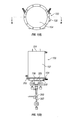
- Figure 1(A) depicts a top view of the evaporator 100
- Figure 1(B) depicts a side view of the evaporator 100
- Figure 2 depicts a cross-sectional view of the evaporator 100 taken at section A-A' of the Figure 1(A) .
- substrate refers to any surface upon which a metal-containing film is deposited by vapor deposition.
- first, second, third etc. may be used herein to describe various elements, components, regions, layers and/or sections, these elements, components, regions, layers and/or sections should not be limited by these terms. These terms are only used to distinguish one element, component, region, layer or section from another element, component, region, layer or section. Thus, a first element, component, region, layer or section discussed below could be termed a second element, component, region, layer or section without departing from the teachings of the present invention.
- relative terms such as “lower” or “bottom” and “upper” or “top,” may be used herein to describe one element's relationship to another elements as illustrated in the Figures. It will be understood that relative terms are intended to encompass different orientations of the device in addition to the orientation depicted in the Figures. For example, if the device in one of the figures is turned over, elements described as being on the “lower” side of other elements would then be oriented on “upper” sides of the other elements. The exemplary term “lower,” can therefore, encompasses both an orientation of “lower” and “upper,” depending on the particular orientation of the figure.
- Exemplary embodiments are described herein with reference to cross section illustrations that are schematic illustrations of idealized embodiments. As such, variations from the shapes of the illustrations as a result, for example, of manufacturing techniques and/or tolerances, are to be expected. Thus, embodiments described herein should not be construed as limited to the particular shapes of regions as illustrated herein but are to include deviations in shapes that result, for example, from manufacturing. For example, a region illustrated or described as flat may, typically, have rough and/or nonlinear features. Moreover, sharp angles that are illustrated may be rounded. Thus, the regions illustrated in the figures are schematic in nature and their shapes are not intended to illustrate the precise shape of a region and are not intended to limit the scope of the present claims.
- an evaporator in fluid communication with a first heat exchanger and disposed in proximity to the first heat exchanger such that precursors from the first heat exchanger are supplied to the evaporator at fairly constant temperatures over extended periods of time.
- the temperature of the precursor supplied by the first heat exchanger is the same as the temperature of the precursor already present in the evaporator.
- the evaporator thus receives a supply of precursor that is maintained at a constant temperature. This minimizes any fluctuations in the quality of semiconductors or other devices manufactured using the evaporator.
- the fluctuations in temperature or pressure of the precursor in the evaporator are minimized over extended periods of time. This results in the production of uniform and high quality (e.g., reproducible) metal-containing films over large periods of time.
- the first heat exchanger contacts the evaporator directly so that the precursor heated in the first heat exchanger travels to the evaporator without any loss of heat to the surroundings.
- the precursor from the first heat exchanger is discharged into the evaporator and not into a jacket that surrounds the evaporator.
- the fluid heated in the heat exchanger is a reactive fluid (precursor) that is used for coating a substrate.
- the distance between heat exchanger and evaporator should be as short as possible but could be any length as long as the tubing connecting heat exchanger and evaporator is perfectly heat insulated.
- the variation in temperature of the precursor in the fluid path that extends from the center of the first heat exchanger to the evaporator is less than or equal to about ⁇ 0.1 °C, specifically less than or equal to about ⁇ 0.2°C, and more specifically less than or equal to about ⁇ 0.5°C when the ambient temperature around the heat exchanger and the evaporator fluctuates by a temperature of up to about ⁇ 15°C, specifically by a temperature of up to about ⁇ 25°C, and more specifically by a temperature of up to about ⁇ 35°C.
- the variation in temperature of the precursor in the fluid path that extends from the center of the first heat exchanger to the evaporator is less than or equal to about ⁇ 0.1°C, specifically less than or equal to about ⁇ 0.2°C, and more specifically less than or equal to about ⁇ 0.5°C.
- the temperature in the precursor contained in first heat exchange not varying by an amount of greater than or equal to about ⁇ 0.1°C, specifically greater than or equal to about ⁇ 0.2°C, and more specifically greater than or equal to about ⁇ 0.5°C over a period of greater than or equal to about 24 hours, specifically greater than or equal to about 36 hours and more specifically greater than or equal to about 48 hours.
- Minimal variation as referred to herein is ⁇ 0.5% of the vapor pressure of the precursor, which generally translates to ⁇ 0.125°C fluctuation in the temperature.
- the liquid is trimethylgallium
- Figure 1(A) depicts a top view of the evaporator 100
- Figure 1(B) depicts a side view of the evaporator 100
- Figure 2 depicts a cross-sectional view of the evaporator 100 taken at section A-A' of the Figure 1(A)
- the evaporator 100 comprises an outer casing 102 that has first end 104 and a second end 106.
- the outer casing 102 of the evaporator 100 encloses an inner casing 110 that contains the precursor.
- the inner casing 110 encloses a first conduit 210 and a second conduit 214 for discharging and removing a carrier gas from the evaporator 100 respectively.
- the first conduit is an inverted U-shaped conduit 210, while the second conduit is a J-shaped conduit 214.
- the inner casing 110 also contacts a first precursor conduit 306 that is in fluid communication with a heat exchanger 300.
- the first precursor conduit 306 contacts a second precursor conduit 302.
- the second precursor conduit 302 has a narrower cross-section that the first precursor conduit 306.
- the second precursor conduit 302 is enveloped by the heat exchanger 300 as close as possible to the evaporator 100.
- the space 118 between the outer casing 102 and the inner casing 110 is filled with a first fluid (e.g., water) that serves to control the temperature of the precursor that is disposed in the inner casing 110.
- the first fluid enters the space 118 through a port 130 and exits the space through a port 132.
- the first end 104 of the outer casing 102 is closed to the environment, while the second end 106 has a first flange 108 that is in communication with an opposing second flange 202 of a plate 200.
- the first flange 108 and the opposing second flange 202 are in communication with one another via a seal or a gasket 208 that prevents the leakage of the carrier fluid or the precursor.
- the first flange 108 and the opposing second flange 202 may be sealed together by nuts and bolts, screw threads, clamps or an adhesive bond if desired.
- the outer casing 102 can have a hole or a plurality of holes in which are disposed conduits that permit the passage of the carrier fluid and the precursor into the evaporator 100. In an exemplary embodiment, these holes are disposed in the plate 200.
- the outer casing 102 has a first hole 112, a second hole 114 and a third hole 116. Disposed in the first hole 112 and the second hole 114 and are the inverted U-shaped conduit 210 and the inverted J-shaped conduit 214 respectively. Disposed in the third hole 116 is a conduit 306 that is in fluid communication with the heat exchanger 300.
- the plate 200 has a first hole 112, a second hole 114 and a third hole 116 through which pass the inverted U-shaped conduit 210, the inverted J-shaped conduit 214 and a conduit 306 that is in fluid communication with the heat exchanger 300 respectively.
- the outer casing 102 and the inner casing 110 can have any desired cross-sectional geometry measured perpendicular to the axis BB'.
- the inner casing 110 is mounted on the plate 200 and can be concentrically or eccentrically mounted with respect to the outer casing 102.
- the inner casing 110 is detachably attached to the plate 200 by nuts and bolts, screw threads, and the like.
- the inner casing 110 is fixedly attached to the plate 200 by welding.
- the entire heat exchanger 300 may be integral with the plate 200.
- the inner casing 110 is screwed onto the plate 200 by screw-threads.
- a gasket may be disposed between the inner casing 110 and the plate 200 to prevent leaks of the precursor or the carrier fluid.
- the volume between the inner casing 110 and the outer casing 102 contains a heating or cooling medium the temperature of which is maintained within ⁇ 0.05°C. It is desirable for any electronic devices or controllers that regulate the flow of the heating or cooling medium to evaporator to regulate the flow of the heating or cooling fluid such that the precursor displays a vapor pressure constancy of ⁇ 0.5% which translates into a temperature constancy of ⁇ 0.125°C.
- An inverted U-shaped conduit 210 having a first port 204 is disposed in the first hole 112.
- An inverted J-shaped conduit 214 having a second port 206 is disposed in the second hole 114.
- a carrier fluid enters the evaporator 100 via the first port 204 and leaves via the second port 206.
- the first port 204, the second port 206, and the conduit 302 of the heat exchanger 300 each have a valve for controlling the input into the evaporator 100.
- the first port 204 is in fluid communication with an inverted U-shaped conduit 210.
- the other end of the inverted U-shaped conduit 210 is in fluid communication with a sparger 212.
- the sparger 212 has a porous or perforated surface to permit the carrier fluid that is introduced into the first port 204 to be dispersed through the precursor contained in the inner casing 110.
- the sparger 212 has a diameter that is almost equal to the diameter of the inner casing 110.
- the circumferential perimeter of the sparger 212 is almost equal to the inner circumference of the inner casing 110.
- the sparger can have holes to accommodate the inverted U-shaped conduit and the J-shaped conduit.
- the sparger can have a diameter that is small enough to permit the inverted U-shaped conduit and the inverted J-shaped conduit to be located between the circumferential perimeter of the sparger 212 and the inner circumference of the inner casing 110.
- the sparger 212 can be a hollow cylinder that has a porous or perforated surface though which the carrier fluid can be dispersed through the precursor.
- the porous surface can comprise a foam that permits the carrier fluid to be dispersed in the form of small bubbles through the precursor.
- the foam has pores of about 1 micrometer to about 50 micrometers and can comprise a metal, a ceramic, a polymer, or combinations thereof.
- the sparger comprises a perforated plate with a hole size of about 1mm.
- the second port 206 is in fluid communication with an inverted J-shaped conduit 214.
- the other end of the J-shaped conduit is protected by a splash-shield 216.
- the splash-shield 216 is a plate that is situated about 3 to about 10 millimeters, specifically about 5 millimeters in front of the end of the J-shaped conduit 216.
- the carrier fluid entrained with the precursor is forced around the splash shield 216 to travel through to the second port 206, which simultaneously prevents droplets of the precursor from doing the same.
- the splash-shield 216 faces the inverted U-tube 210.
- the splash-shield may face away from the inverted U-tube 210.
- the plate 200 has a heating or cooling jacket 230 disposed thereon.
- the heating or cooling jacket 230 has an inlet port 220 and an exit port 222 through which the heating or cooling fluid flows into and out of the heating or cooling jacket 230.
- the inverted U-shaped conduit 210, the inverted J-shaped conduit 214, the splash-shield 216, the inner casing 110, the sparger 212, the first precursor conduit 306, and the second precursor conduit 302, all of which contact the precursor, may be manufactured from materials that can withstand the temperatures of the carrier fluid and/or the precursor. It is also desirable for the material to not react with or corrode under the influence of the precursor and/or the carrier fluid.
- the carrier fluid comprises hydrogen, oxygen, argon, helium, nitrogen, or the like, or a combination comprising at least one of the foregoing carrier fluids.
- the precursor can be a gas or a liquid and comprises boron tribromide, phosphorous oxychloride, phosphorous tribromide, silicon tetrachloride, dichlorosilane, silicon tetrabromide, arsenic trichloride, arsenic tribromide, antimony pentachloride, trimethylgallium (TMGa), triethylgallium (TEGa), trimethylaluminum (TMA1), ethyldimethylindium, tertiary-butylarsine, tertiary-butylphosphine, silane (SiH 4 ), dichlorosilane (SiH 2 C1 2 ), germanium tetrachloride (GeCl 4 ), stannic chloride (SnCl 4 ), trimethylarsenic (CH 3 ) 3 As, trimethylgallium (CH 3 ) 3 Ga, triethylgallium (C
- the precursor it is desirable for the precursor to be a liquid.
- liquids are germanium tetrachloride (GeCl 4 ), stannic chloride (SnCl 4 ), trimethylarsenic (CH 3 ) 3 As, trimethylgallium (CH 3 ) 3 Ga, triethylgallium (C 2 H 5 ) 3 Ga, isobutylgermane (C 4 H 9 )GeH 3 , diethyltelluride (C 2 H 5 ) 2 Te, diisopropyltelluride (C 3 H 7 ) 2 Te, dimethylzinc (CH 3 ) 2 Zn, diethylzinc (C 2 H 5 ) 2 Zn, trimethylantimony (CH 3 ) 3 Sb, triethylantimony (C 2 H 5 ) 3 Sb, or the like, or a combination comprising at least one of the foregoing precursors.
- the U-shaped conduit 210, the inverted J-shaped conduit 214, the splash-shield 216, the inner casing 110, the sparger 212 may be manufactured from a metal, a ceramic, a plastic or a combination thereof.
- Suitable metals are stainless steel such as, for example SS316, titanium, titanium alloys, noble metals such as gold, silver, platinum, rhodium, palladium, iridium, aluminum, copper, or the like, or a combination comprising at least one of the foregoing metals.
- Suitable ceramics are silica, quartz, alumina, titania, or the like, or a combination comprising at least one of the foregoing ceramics. It is desirable to use polymers that have a glass transition temperature and/or a crystalline melting point that is greater than or equal to about room temperature.
- the polymers may be thermoplastic, thermosets, or combinations thereof.
- Suitable polymers are polytetrafluoroethylene, polydimethylsiloxane, polyether ether ketone, polyolefins (e.g., polyethylene, polypropylene, or the like), polyvinylchloride, polystyrene, polyester, polyacrylates, phenolics, or the like, or a combination comprising at least one of the foregoing polymers.
- the heat exchanger 300 comprises the second precursor conduit 302 and an outer jacket 304.
- the second precursor conduit 302 is in fluid communication with the first precursor conduit 306 that is disposed in the third hole 116 in the plate 200 and serves to charge the inner casing 110 of the evaporator 100 with the precursor.
- the plate 200 also has disposed in it a level detection device 308.
- the level detection device 308 has markings on it to show a low level mark 120, a high level mark 122, a start fill mark 124 and a high level mark (also known as a "stop fill” mark) 126 for the precursor. It is desirable to maintain the precursor in the inner casing 110 between the start fill mark 124 and the stop fill mark 126.
- the level detection device 308 can be an acoustic device, a pressure column or an optical device. Combinations of the aforementioned level detection devices can be used for enhanced accuracy.
- the first precursor conduit 306 also contains a thermocouple or a temperature sensitive resistor 312 that measures the temperature of the precursor in the first precursor conduit 306 after it has left the heat exchanger 300.
- the thermocouple or temperature sensitive resistor 312 is in electrical communication with a controller (not shown) that supplies heat to the heat exchanger 300.
- the controller can be a computer, a centralized processing unit, or the like.
- the controller communicates with the heat exchanger 300 to adjust the temperature of its heat source, which in turn adjusts the temperature of the precursor.
- the heat exchanger 300 may be heated or cooled by using a fluid that enters the outer jacket 304 through port 320 and exits through port 322.
- the outer jacket 304 may comprise a resistive heating coil that can be used to heat the precursor.
- the precursor level in the inner casing 110 can be controlled by various means.
- the precursor content in the evaporator is preferably controlled by monitoring the mass or weight of the evaporator.
- the evaporator is mounted on a weight scale (not shown) to continuously measure the mass or weight of the vessel.
- a signal from scale is sent to a controller (not shown), which controls operation of the liquid supply system based on the weight measurement.
- the controller sends a signal to a valve on the conduit 302, which it continuously controls the flux of liquid introduced into the evaporator to maintain a constant liquid level therein.
- liquid level sensors for example, float switches, to detect high and/or low liquid levels in the evaporator can be installed. These sensors can be connected to an alarm system to alert the operator of any abnormal condition.
- an optional sight glass assembly can be installed in the vessel. The sight glass assembly should be leak proof so as to avoid leakage and contamination of the precursor.
- the sight glass is preferably constructed of a quartz lens sealed with an o-ring.
- Figures 1(A), 1(B) and 2 display only a single heat exchanger in fluid communication with a single evaporator, it is possible to have multiple heat exchangers in fluid communication with a single evaporator.
- a plate 200 having a first hole 112, a second hole 114, and a third hole 116 is fitted with the inverted U-shaped conduit 210, the inverted J-shaped conduit 214 and the first precursor conduit 306 to which is affixed the heat exchanger 300 and the level detection device 308.
- the inverted J-shaped conduit 214 has the splash shield disposed thereon.
- the inner casing 110 is screwed onto the plate 200.
- the inner casing 100 is welded onto the plate 200.
- a seal is disposed between the inner casing and the plate 200.
- the inner casing 110 covers the U-shaped conduit 210, the inverted J-shaped conduit 214 and the first precursor conduit 306 to which is affixed the heat exchanger 300 and the level detection device 308.
- the opposing second flange 202 of the plate 200 is then aligned with the first flange 108 and the two flanges are bolted together to encapsulate the gasket 208.
- a precursor from a storage tank (not shown) is first introduced into the heat exchanger 300.
- the storage tank maintains the precursor at a temperature that is substantially similar to the temperature of the evaporator 100.
- the heat exchanger 300 heats or cools the precursor to a desired temperature.
- a controller that is in communication with the evaporator 100 determines the amount of the carrier fluid and the amount of the precursor that are desired in the evaporator. The desired amount of the precursor is discharged into the evaporator 100 and is stored in the inner casing 110.
- the precursor is discharged from the heat exchanger 300 to the evaporator 100 in amounts that are determined by the controller.
- the carrier fluid is discharged from a separate storage tank (not shown) to the evaporator 100.
- the carrier fluid enters the inverted U-shaped conduit and is discharged via the sparger 212 into the inner casing 110.
- the inner casing 110 contains the precursor at the desired temperature.
- the carrier fluid bubbles through the precursor in the inner casing 110 and some of the precursor in entrained in the carrier fluid.
- the carrier fluid with the precursor entrained thereon then travels through the inverted J-shaped conduit 214 to the processing chamber where it is desired.
- the heat exchanger 300 is disposed so close to the evaporator 100, that the weight ratio of the carrier fluid to the precursor is substantially constant after being removed from the evaporator by the second conduit. This happens even when the ambient temperature fluctuates by a amount of up to ⁇ 15°C, specifically by an amount of up to ⁇ 25°C, and more specifically by an amount of up to ⁇ 35°C.
- the heat exchanger 300 is integral with the evaporator 100.
- the heat exchanger 300 is disposed so close to the evaporator 100, that the weight ratio (concentration) of the carrier fluid to the precursor does not change by an amount of greater than or equal to about 0.1%, specifically greater than or equal to about 0.2%, and more specifically greater than or equal to about 0.5%. This happens even when the ambient temperature fluctuates by a amount of up to ⁇ 15°C, specifically by an amount of up to ⁇ 25°C, and more specifically by an amount of up to ⁇ 35°C.
Landscapes
- Chemical & Material Sciences (AREA)
- Chemical Kinetics & Catalysis (AREA)
- Engineering & Computer Science (AREA)
- General Chemical & Material Sciences (AREA)
- Materials Engineering (AREA)
- Mechanical Engineering (AREA)
- Metallurgy (AREA)
- Organic Chemistry (AREA)
- Inorganic Chemistry (AREA)
- Dispersion Chemistry (AREA)
- Physics & Mathematics (AREA)
- Plasma & Fusion (AREA)
- Chemical Vapour Deposition (AREA)
- Feeding, Discharge, Calcimining, Fusing, And Gas-Generation Devices (AREA)
- Vaporization, Distillation, Condensation, Sublimation, And Cold Traps (AREA)
- Physical Or Chemical Processes And Apparatus (AREA)
Abstract
Description
- This disclosure relates to a method for constant concentration evaporation and an article using the same.
- Metal-containing films are used in a variety of electronic and optoelectronic applications. Chemical vapor deposition ("CVD") processes are often used in the electronics industry, particularly the semiconductor industry, to deposit metal-containing layers (or films) on substrates. Metal-containing precursors and optionally dopants (hereinafter "precursors") are delivered to a deposition reactor and deposited on a substrate to form a metal-containing film. The precursors are generally provided in bubblers (also referred to as cylinders or evaporators). In use, a carrier fluid enters the bubbler, passes through the precursor, becomes saturated with the precursor, and then the carrier gas/precursor vapor mixture exits the cylinder and is directed to the deposition reaction chamber. In the deposition chamber, a layer or film containing the metal from the precursor is grown on a substrate. The substrates can be any suitable material such as silicon wafers, sapphire wafers, InP wafers, GaAs wafers, SiC wafers, germanium wafers, among others.
- Bubblers, including those utilized in commercially available automatic refill systems, rely on relatively large fluid volumes to compensate for deviations in fluid level that can negatively effect the resulting vapor concentration. Since vapor sources in the fiber optics and semiconductor industries are often hazardous fluids, it is desirable to reduce the maximum allowable volume of many of these fluids within the work place. It is therefore desirable to reduce the required fluid volume at the point of vapor generation without compromising vapor concentration control.
- A bubbler container comprises a single vessel, which holds an expendable volume of the precursor. A carrier fluid is introduced into the fluid column, travels up through, and exits the precursor surface into a headspace. As the carrier fluid passes through the fluid column it becomes entrained with vapor, which results in a corresponding reduction of the fluid volume. The entrained vapor is then transported to the surface of a substrate where it chemically reacts and forms a material film. If there is a variation in the temperature or pressure of the carrier fluid or the fluid, it results in the formation of non-uniform products.
- In order to produce semiconductors or fibers that are within a narrow range of specification and that are reproducible and interchangeable, it is desirable to use a vapor concentration that does not fluctuate during the manufacturing processes. It is therefore desirable to control the temperature of the carrier fluid containing the vapor, the carrier fluid residence time (e.g., the liquid level in the bubbler) and the vapor pressure of the carrier fluid to obtain reproducible and consistent products.
- One variable that affects the concentration of the chemical vapor in the carrier fluid is the temperature of the precursor. The vapor pressure of the volatile precursor is a function of the temperature of the precursor. Thus, at any given temperature, the carrier fluid becomes saturated with the chemical vapor at an equilibrium condition. The carrier fluid and chemical vapor coexist at their equilibrium saturation conditions as long as the temperature remains constant. If, however, the temperature drops, a portion of the chemical vapor condenses from the vapor state, resulting in a change in the concentration of the chemical vapor in the carrier fluid.
- To control the temperature in the bubbler, commercially available units use a combined chiller and heater unit. These devices provide a convenient means of adjusting the temperature in the evaporator independent of the ambient temperature. To prevent condensation of the chemical vapor from the carrier fluid as it is delivered to the process equipment, the gas is not to be subjected to a temperature lower than that at which the saturation occurs. Low ambient temperature requires heating of the precursor, high ambient temperature requires cooling of the precursor.
- During the saturation process, conversion of the precursor to a vapor results in the removal of heat from the liquid. The net effect of this heat removal is that the temperature of the precursor may drop below the control temperature of the cooling or heating medium. The temperature control unit attempts to compensate for the temperature drop by increasing the heat flow to the evaporator. However, conventional temperature control units do not adequately maintain a set temperature of the precursor in the evaporator during use.
- Yet another variable that can affect the chemical vapor concentration in the carrier fluid is the pressure of the carrier fluid. Commercially available devices have made use of mechanical pressure regulators, which rely on springs and diaphragms to sense and control pressure. With such commercially available mechanical devices, however, there is an inherent delay in responding to system changes. This can result in pressure fluctuations, which, in turn, produce variations in the chemical vapor concentration.
-
U.S. Patent No. 6,135,433 to Nurmi teaches controlling the temperature and the pressure of the precursor in the bubbler. The temperature is controlled by means of a heat jacket disposed around the bubbler and a temperature probe that is disposed in the precursor of the bubbler, while the pressure is controlled by pressure transducers in the carrier fluid line. However, the precursor is contained in storage tanks that are maintained at ambient conditions. This causes the precursor being supplied to the bubbler to be at different temperatures. In addition, since the heater is located on the outer surface of the bubbler, ambient temperature variations affect the performance of the heater and consequently the temperature of the precursor in the bubbler undergoes variations. These temperature variations lead to variations in product quality, which is undesirable. -
U.S. Patent No. 7,011,299 to Curran teaches a method and a system for controlling the delivery of vapor from a bubbler containing a supply of precursor. The vapor pressure of the carrier fluid and the precursor is controlled by controlling the pressure within the headspace of the bubbler to that of the precursor line, thus creating repeatable fluid level based on pressure and fluid dynamics and not relying on conventional level sensors and controllers. This system suffers from the drawback that the temperature of the carrier fluid and the temperature of the precursor are not closely controlled, leading to the concentration variations in the amount of the chemical deposited on the various substrates. - It is therefore desirable to have a bubbler where temperature and pressure variations are minimized so that product quality is stabilized.
- Disclosed herein is a device comprising an evaporator; and a heat exchanger; the heat exchanger being in fluid communication with the evaporator; the evaporator comprising an outer casing; and an inner casing that is disposed within the outer casing; the inner casing contacting a plate; wherein the inner casing encloses a first conduit that is operative to introduce a carrier fluid into the evaporator; and a second conduit that is operative to remove the carrier fluid entrained with a precursor; wherein the outer casing is detachably attached to the plate; the plate contacting a first precursor conduit that is operative to introduce the precursor into the evaporator from the heat exchanger; where the heat exchanger is disposed proximate to the evaporator at a distance effective to maintain the precursor in the evaporator at a substantially constant temperature when the ambient temperature around the heat exchanger and the evaporator fluctuates by an amount of up to about ± 35°C.
- Disclosed herein too is a method comprising heating or cooling a precursor in a heat exchanger; discharging the precursor from the heat exchanger to an evaporator; the evaporator comprising an outer casing; and an inner casing that is disposed within the outer casing; the inner casing contacting a plate; wherein the inner casing encloses a first conduit; and a second conduit; introducing a carrier fluid into the evaporator via the first conduit; sparging the precursor with the carrier fluid; and removing the carrier fluid entrained with the precursor from the evaporator via the second conduit; where the proximity of the heat exchanger to the evaporator is effective to maintain the precursor in the evaporator at a substantially constant temperature when the ambient temperature around the heat exchanger and the evaporator fluctuates by an amount of up to about ± 35°C.
- Disclosed herein too is a method for manufacturing a device comprising disposing an inverted U-shaped conduit in a first hole, an inverted J-shaped conduit in a second hole and a first precursor conduit in a third hole on a plate; the plate being affixed with a heat exchanger; and disposing an inner casing and an outer casing on a side of the plate that is opposed to a side where the heat exchanger contacts the plate; the inner casing being contained in the outer casing; the inner casing enclosing the inverted U-shaped conduit, the inverted J-shaped conduit and the first precursor conduit.
-
Figure 1(A) depicts a top view of theevaporator 100; -
Figure 1(B) depicts a side view of theevaporator 100; and -
Figure 2 depicts a cross-sectional view of theevaporator 100 taken at section A-A' of theFigure 1(A) . - Like reference numerals refer to like elements throughout.
- It will be understood that when an element is referred to as being "on" another element, it can be directly on the other element or intervening elements may be present therebetween. In contrast, when an element is referred to as being "directly on" another element, there are no intervening elements present. As used herein, the term "and/or" includes any and all combinations of one or more of the associated listed items. As used herein, "substrate" refers to any surface upon which a metal-containing film is deposited by vapor deposition.
- It will be understood that, although the terms first, second, third etc. may be used herein to describe various elements, components, regions, layers and/or sections, these elements, components, regions, layers and/or sections should not be limited by these terms. These terms are only used to distinguish one element, component, region, layer or section from another element, component, region, layer or section. Thus, a first element, component, region, layer or section discussed below could be termed a second element, component, region, layer or section without departing from the teachings of the present invention.
- The terminology used herein is for the purpose of describing particular embodiments only and is not intended to be limiting. As used herein, the singular forms "a," "an" and "the" are intended to include the plural forms as well, unless the context clearly indicates otherwise. It will be further understood that the terms "comprises" and/or "comprising," or "includes" and/or "including" when used in this specification, specify the presence of stated features, regions, integers, steps, operations, elements, and/or components, but do not preclude the presence or addition of one or more other features, regions, integers, steps, operations, elements, components, and/or groups thereof.
- Furthermore, relative terms, such as "lower" or "bottom" and "upper" or "top," may be used herein to describe one element's relationship to another elements as illustrated in the Figures. It will be understood that relative terms are intended to encompass different orientations of the device in addition to the orientation depicted in the Figures. For example, if the device in one of the figures is turned over, elements described as being on the "lower" side of other elements would then be oriented on "upper" sides of the other elements. The exemplary term "lower," can therefore, encompasses both an orientation of "lower" and "upper," depending on the particular orientation of the figure. Similarly, if the device in one of the figures is turned over, elements described as "below" or "beneath" other elements would then be oriented "above" the other elements. The exemplary terms "below" or "beneath" can, therefore, encompass both an orientation of above and below.
- Unless otherwise defined, all terms (including technical and scientific terms) used herein have the same meaning as commonly understood by one of ordinary skill in the art to which this invention belongs. It will be further understood that terms, such as those defined in commonly used dictionaries, should be interpreted as having a meaning that is consistent with their meaning in the context of the relevant art and the present disclosure, and will not be interpreted in an idealized or overly formal sense unless expressly so defined herein.
- Exemplary embodiments are described herein with reference to cross section illustrations that are schematic illustrations of idealized embodiments. As such, variations from the shapes of the illustrations as a result, for example, of manufacturing techniques and/or tolerances, are to be expected. Thus, embodiments described herein should not be construed as limited to the particular shapes of regions as illustrated herein but are to include deviations in shapes that result, for example, from manufacturing. For example, a region illustrated or described as flat may, typically, have rough and/or nonlinear features. Moreover, sharp angles that are illustrated may be rounded. Thus, the regions illustrated in the figures are schematic in nature and their shapes are not intended to illustrate the precise shape of a region and are not intended to limit the scope of the present claims.
- Disclosed herein is an evaporator in fluid communication with a first heat exchanger and disposed in proximity to the first heat exchanger such that precursors from the first heat exchanger are supplied to the evaporator at fairly constant temperatures over extended periods of time. By disposing the evaporator in proximity to the first heat exchanger, the effects of ambient temperature conditions on the temperature of the chemical liquid is minimized, thus permitting the evaporator to receive the precursor at a substantially constant temperature under a variety of ambient temperature conditions. As a result, the temperature of the precursor in the evaporator remains substantially constant over large periods of time.
- In one embodiment, the temperature of the precursor supplied by the first heat exchanger is the same as the temperature of the precursor already present in the evaporator. The evaporator thus receives a supply of precursor that is maintained at a constant temperature. This minimizes any fluctuations in the quality of semiconductors or other devices manufactured using the evaporator. In short, by connecting the heat exchanger directly to the evaporator and by minimizing the piping between the heat exchanger and the evaporator, the fluctuations in temperature or pressure of the precursor in the evaporator are minimized over extended periods of time. This results in the production of uniform and high quality (e.g., reproducible) metal-containing films over large periods of time.
- The first heat exchanger contacts the evaporator directly so that the precursor heated in the first heat exchanger travels to the evaporator without any loss of heat to the surroundings. In one embodiment, the precursor from the first heat exchanger is discharged into the evaporator and not into a jacket that surrounds the evaporator. In other words, the fluid heated in the heat exchanger is a reactive fluid (precursor) that is used for coating a substrate.
- The distance between heat exchanger and evaporator should be as short as possible but could be any length as long as the tubing connecting heat exchanger and evaporator is perfectly heat insulated.
- In one embodiment, there is no variation in temperature of the precursor in the fluid path that extends from the center of the first heat exchanger to the evaporator (or bubbler) when the ambient temperature around the heat exchanger and the evaporator fluctuates by a temperature of up to about ± 15°C, specifically by a temperature of up to about ± 25°C, and more specifically by a temperature of up to about ± 35°C.
- In another embodiment, the variation in temperature of the precursor in the fluid path that extends from the center of the first heat exchanger to the evaporator is less than or equal to about ±0.1 °C, specifically less than or equal to about ±0.2°C, and more specifically less than or equal to about ±0.5°C when the ambient temperature around the heat exchanger and the evaporator fluctuates by a temperature of up to about ± 15°C, specifically by a temperature of up to about ± 25°C, and more specifically by a temperature of up to about ± 35°C.
- In one embodiment, there is no variation in temperature of the precursor in the fluid path that extends from the center of the first heat exchanger to the evaporator. In another embodiment, the variation in temperature of the precursor in the fluid path that extends from the center of the first heat exchanger to the evaporator is less than or equal to about ±0.1°C, specifically less than or equal to about ±0.2°C, and more specifically less than or equal to about ±0.5°C. This results in the temperature in the precursor contained in first heat exchange not varying by an amount of greater than or equal to about ±0.1°C, specifically greater than or equal to about ±0.2°C, and more specifically greater than or equal to about ±0.5°C over a period of greater than or equal to about 24 hours, specifically greater than or equal to about 36 hours and more specifically greater than or equal to about 48 hours.
- By supplying fresh precursor to the evaporator at the same temperature as the precursor already present in the evaporator, temperature and pressure fluctuations of the precursor in the evaporator are reduced and the quality of products manufactured from the precursor suffer minimal variation. Minimal variation as referred to herein is ±0.5% of the vapor pressure of the precursor, which generally translates to ± 0.125°C fluctuation in the temperature. For example, if the liquid is trimethylgallium, it is desirable for the combination of the evaporator and the heat exchanger to control the vapor pressure of the trimethylgallium to within ±0.5% of the desired vapor pressure. Controlling the vapor pressure to within ±0.5% of the desired vapor pressure restricts temperature fluctuations within the trimethyl gallium to within ± 0.125°C of a desired temperature.
-
Figure 1(A) depicts a top view of theevaporator 100, whileFigure 1(B) depicts a side view of theevaporator 100.Figure 2 depicts a cross-sectional view of theevaporator 100 taken at section A-A' of theFigure 1(A) . With reference now to theFigures 1(A), 1(B) and2 , theevaporator 100 comprises anouter casing 102 that hasfirst end 104 and asecond end 106. Theouter casing 102 of theevaporator 100 encloses aninner casing 110 that contains the precursor. Theinner casing 110 encloses afirst conduit 210 and asecond conduit 214 for discharging and removing a carrier gas from theevaporator 100 respectively. In one embodiment the first conduit is an invertedU-shaped conduit 210, while the second conduit is a J-shapedconduit 214. Theinner casing 110 also contacts afirst precursor conduit 306 that is in fluid communication with aheat exchanger 300. Thefirst precursor conduit 306 contacts asecond precursor conduit 302. In an exemplary embodiment, thesecond precursor conduit 302 has a narrower cross-section that thefirst precursor conduit 306. Thesecond precursor conduit 302 is enveloped by theheat exchanger 300 as close as possible to theevaporator 100. - The
space 118 between theouter casing 102 and theinner casing 110 is filled with a first fluid (e.g., water) that serves to control the temperature of the precursor that is disposed in theinner casing 110. The first fluid enters thespace 118 through aport 130 and exits the space through aport 132. - The
first end 104 of theouter casing 102 is closed to the environment, while thesecond end 106 has afirst flange 108 that is in communication with an opposingsecond flange 202 of aplate 200. Thefirst flange 108 and the opposingsecond flange 202 are in communication with one another via a seal or agasket 208 that prevents the leakage of the carrier fluid or the precursor. Thefirst flange 108 and the opposingsecond flange 202 may be sealed together by nuts and bolts, screw threads, clamps or an adhesive bond if desired. - The
outer casing 102 can have a hole or a plurality of holes in which are disposed conduits that permit the passage of the carrier fluid and the precursor into theevaporator 100. In an exemplary embodiment, these holes are disposed in theplate 200. - In one embodiment (not shown), the
outer casing 102 has afirst hole 112, asecond hole 114 and athird hole 116. Disposed in thefirst hole 112 and thesecond hole 114 and are the invertedU-shaped conduit 210 and the inverted J-shapedconduit 214 respectively. Disposed in thethird hole 116 is aconduit 306 that is in fluid communication with theheat exchanger 300. In an exemplary embodiment (shown in theFigure 2 ), theplate 200 has afirst hole 112, asecond hole 114 and athird hole 116 through which pass the invertedU-shaped conduit 210, the inverted J-shapedconduit 214 and aconduit 306 that is in fluid communication with theheat exchanger 300 respectively. - The
outer casing 102 and theinner casing 110 can have any desired cross-sectional geometry measured perpendicular to the axis BB'. Theinner casing 110 is mounted on theplate 200 and can be concentrically or eccentrically mounted with respect to theouter casing 102. Theinner casing 110 is detachably attached to theplate 200 by nuts and bolts, screw threads, and the like. In one embodiment, theinner casing 110 is fixedly attached to theplate 200 by welding. In a further embodiment (not shown), theentire heat exchanger 300 may be integral with theplate 200. - In an exemplary embodiment, the
inner casing 110 is screwed onto theplate 200 by screw-threads. A gasket may be disposed between theinner casing 110 and theplate 200 to prevent leaks of the precursor or the carrier fluid. The volume between theinner casing 110 and theouter casing 102 contains a heating or cooling medium the temperature of which is maintained within ±0.05°C. It is desirable for any electronic devices or controllers that regulate the flow of the heating or cooling medium to evaporator to regulate the flow of the heating or cooling fluid such that the precursor displays a vapor pressure constancy of ±0.5% which translates into a temperature constancy of ±0.125°C. - An inverted
U-shaped conduit 210 having afirst port 204 is disposed in thefirst hole 112. An inverted J-shapedconduit 214 having asecond port 206 is disposed in thesecond hole 114. A carrier fluid enters theevaporator 100 via thefirst port 204 and leaves via thesecond port 206. Thefirst port 204, thesecond port 206, and theconduit 302 of theheat exchanger 300 each have a valve for controlling the input into theevaporator 100. - The
first port 204 is in fluid communication with an invertedU-shaped conduit 210. The other end of the invertedU-shaped conduit 210 is in fluid communication with asparger 212. Thesparger 212 has a porous or perforated surface to permit the carrier fluid that is introduced into thefirst port 204 to be dispersed through the precursor contained in theinner casing 110. In one embodiment, thesparger 212 has a diameter that is almost equal to the diameter of theinner casing 110. In other words, the circumferential perimeter of thesparger 212 is almost equal to the inner circumference of theinner casing 110. In this embodiment, the sparger can have holes to accommodate the inverted U-shaped conduit and the J-shaped conduit. In another embodiment, the sparger can have a diameter that is small enough to permit the inverted U-shaped conduit and the inverted J-shaped conduit to be located between the circumferential perimeter of thesparger 212 and the inner circumference of theinner casing 110. - In one embodiment, the
sparger 212 can be a hollow cylinder that has a porous or perforated surface though which the carrier fluid can be dispersed through the precursor. In another embodiment, the porous surface can comprise a foam that permits the carrier fluid to be dispersed in the form of small bubbles through the precursor. The foam has pores of about 1 micrometer to about 50 micrometers and can comprise a metal, a ceramic, a polymer, or combinations thereof. In one embodiment, the sparger comprises a perforated plate with a hole size of about 1mm. - The
second port 206 is in fluid communication with an inverted J-shapedconduit 214. The other end of the J-shaped conduit is protected by a splash-shield 216. The splash-shield 216 is a plate that is situated about 3 to about 10 millimeters, specifically about 5 millimeters in front of the end of the J-shapedconduit 216. The carrier fluid entrained with the precursor is forced around thesplash shield 216 to travel through to thesecond port 206, which simultaneously prevents droplets of the precursor from doing the same. As can be seen in theFigure 2 , the splash-shield 216 faces theinverted U-tube 210. In one embodiment (not shown), to further prevent the droplets of the precursor from travelling to thesecond port 206, the splash-shield may face away from the invertedU-tube 210. - The
plate 200 has a heating orcooling jacket 230 disposed thereon. The heating orcooling jacket 230 has aninlet port 220 and anexit port 222 through which the heating or cooling fluid flows into and out of the heating orcooling jacket 230. - The inverted
U-shaped conduit 210, the inverted J-shapedconduit 214, the splash-shield 216, theinner casing 110, thesparger 212, thefirst precursor conduit 306, and thesecond precursor conduit 302, all of which contact the precursor, may be manufactured from materials that can withstand the temperatures of the carrier fluid and/or the precursor. It is also desirable for the material to not react with or corrode under the influence of the precursor and/or the carrier fluid. The carrier fluid comprises hydrogen, oxygen, argon, helium, nitrogen, or the like, or a combination comprising at least one of the foregoing carrier fluids. The precursor can be a gas or a liquid and comprises boron tribromide, phosphorous oxychloride, phosphorous tribromide, silicon tetrachloride, dichlorosilane, silicon tetrabromide, arsenic trichloride, arsenic tribromide, antimony pentachloride, trimethylgallium (TMGa), triethylgallium (TEGa), trimethylaluminum (TMA1), ethyldimethylindium, tertiary-butylarsine, tertiary-butylphosphine, silane (SiH4), dichlorosilane (SiH2C12), germanium tetrachloride (GeCl4), stannic chloride (SnCl4), trimethylarsenic (CH3)3As, trimethylgallium (CH3)3Ga, triethylgallium (C2H5)3Ga, isobutylgermane (C4H9)GeH3, diethyltelluride (C2H5)2Te, diisopropyltelluride (C3H7)2Te, dimethylzinc (CH3)2Zn, diethylzinc (C2H5)2Zn, trimethylantimony (CH3)3Sb, triethylantimony (C2H5)3Sb, trichlorosilane (SiHCl3), ammonia (NH3), boron trichloride (BCl3), chlorine (Cl2), hydrogen chloride (HCl), hydrogen fluoride (HF), chlorine trifluoride (ClF3), trisilane (Si3H8), or the like, or a combination comprising at least one of the foregoing precursors. - In one embodiment, it is desirable for the precursor to be a liquid. Examples of liquids are germanium tetrachloride (GeCl4), stannic chloride (SnCl4), trimethylarsenic (CH3)3As, trimethylgallium (CH3)3Ga, triethylgallium (C2H5)3Ga, isobutylgermane (C4H9)GeH3, diethyltelluride (C2H5)2Te, diisopropyltelluride (C3H7)2Te, dimethylzinc (CH3)2Zn, diethylzinc (C2H5)2Zn, trimethylantimony (CH3)3Sb, triethylantimony (C2H5)3Sb, or the like, or a combination comprising at least one of the foregoing precursors.
- In an exemplary embodiment, the
U-shaped conduit 210, the inverted J-shapedconduit 214, the splash-shield 216, theinner casing 110, thesparger 212 may be manufactured from a metal, a ceramic, a plastic or a combination thereof. - Suitable metals are stainless steel such as, for example SS316, titanium, titanium alloys, noble metals such as gold, silver, platinum, rhodium, palladium, iridium, aluminum, copper, or the like, or a combination comprising at least one of the foregoing metals. Suitable ceramics are silica, quartz, alumina, titania, or the like, or a combination comprising at least one of the foregoing ceramics. It is desirable to use polymers that have a glass transition temperature and/or a crystalline melting point that is greater than or equal to about room temperature. The polymers may be thermoplastic, thermosets, or combinations thereof. Suitable polymers are polytetrafluoroethylene, polydimethylsiloxane, polyether ether ketone, polyolefins (e.g., polyethylene, polypropylene, or the like), polyvinylchloride, polystyrene, polyester, polyacrylates, phenolics, or the like, or a combination comprising at least one of the foregoing polymers.
- The
heat exchanger 300 comprises thesecond precursor conduit 302 and anouter jacket 304. Thesecond precursor conduit 302 is in fluid communication with thefirst precursor conduit 306 that is disposed in thethird hole 116 in theplate 200 and serves to charge theinner casing 110 of theevaporator 100 with the precursor. Theplate 200 also has disposed in it alevel detection device 308. Thelevel detection device 308 has markings on it to show alow level mark 120, ahigh level mark 122, astart fill mark 124 and a high level mark (also known as a "stop fill" mark) 126 for the precursor. It is desirable to maintain the precursor in theinner casing 110 between thestart fill mark 124 and thestop fill mark 126. By maintaining the precursor between these marks the amount of the precursor vapor in the carrier fluid is maintained within desired limits. Thelevel detection device 308 can be an acoustic device, a pressure column or an optical device. Combinations of the aforementioned level detection devices can be used for enhanced accuracy. - The
first precursor conduit 306 also contains a thermocouple or a temperaturesensitive resistor 312 that measures the temperature of the precursor in thefirst precursor conduit 306 after it has left theheat exchanger 300. The thermocouple or temperaturesensitive resistor 312 is in electrical communication with a controller (not shown) that supplies heat to theheat exchanger 300. The controller can be a computer, a centralized processing unit, or the like. - When the temperature of the precursor varies by an amount greater than or equal to about ±0.1°C, specifically greater than or equal to about ±0.5°C, the controller communicates with the
heat exchanger 300 to adjust the temperature of its heat source, which in turn adjusts the temperature of the precursor. In one embodiment, theheat exchanger 300 may be heated or cooled by using a fluid that enters theouter jacket 304 throughport 320 and exits throughport 322. In another embodiment, theouter jacket 304 may comprise a resistive heating coil that can be used to heat the precursor. - The precursor level in the
inner casing 110 can be controlled by various means. In one embodiment, the precursor content in the evaporator is preferably controlled by monitoring the mass or weight of the evaporator. For this purpose, the evaporator is mounted on a weight scale (not shown) to continuously measure the mass or weight of the vessel. A signal from scale is sent to a controller (not shown), which controls operation of the liquid supply system based on the weight measurement. The controller sends a signal to a valve on theconduit 302, which it continuously controls the flux of liquid introduced into the evaporator to maintain a constant liquid level therein. - In another embodiment, as an extra safety check in the event scale malfunctions, liquid level sensors, for example, float switches, to detect high and/or low liquid levels in the evaporator can be installed. These sensors can be connected to an alarm system to alert the operator of any abnormal condition. To allow visual monitoring and observation of the liquid level and dispersion of the carrier fluid in the precursor, an optional sight glass assembly can be installed in the vessel. The sight glass assembly should be leak proof so as to avoid leakage and contamination of the precursor. The sight glass is preferably constructed of a quartz lens sealed with an o-ring.
- While the
Figures 1(A), 1(B) and2 display only a single heat exchanger in fluid communication with a single evaporator, it is possible to have multiple heat exchangers in fluid communication with a single evaporator. - In one embodiment, in one method of manufacturing the
evaporator 100, aplate 200 having afirst hole 112, asecond hole 114, and athird hole 116 is fitted with the invertedU-shaped conduit 210, the inverted J-shapedconduit 214 and thefirst precursor conduit 306 to which is affixed theheat exchanger 300 and thelevel detection device 308. The inverted J-shapedconduit 214 has the splash shield disposed thereon. Theinner casing 110 is screwed onto theplate 200. In one embodiment, theinner casing 100 is welded onto theplate 200. A seal is disposed between the inner casing and theplate 200. Theinner casing 110 covers theU-shaped conduit 210, the inverted J-shapedconduit 214 and thefirst precursor conduit 306 to which is affixed theheat exchanger 300 and thelevel detection device 308. The opposingsecond flange 202 of theplate 200 is then aligned with thefirst flange 108 and the two flanges are bolted together to encapsulate thegasket 208. - In one embodiment, in one method of operating the
evaporator 100, a precursor from a storage tank (not shown) is first introduced into theheat exchanger 300. The storage tank maintains the precursor at a temperature that is substantially similar to the temperature of theevaporator 100. Theheat exchanger 300 heats or cools the precursor to a desired temperature. A controller that is in communication with theevaporator 100 determines the amount of the carrier fluid and the amount of the precursor that are desired in the evaporator. The desired amount of the precursor is discharged into theevaporator 100 and is stored in theinner casing 110. - The precursor is discharged from the
heat exchanger 300 to theevaporator 100 in amounts that are determined by the controller. The carrier fluid is discharged from a separate storage tank (not shown) to theevaporator 100. The carrier fluid enters the inverted U-shaped conduit and is discharged via thesparger 212 into theinner casing 110. Theinner casing 110 contains the precursor at the desired temperature. The carrier fluid bubbles through the precursor in theinner casing 110 and some of the precursor in entrained in the carrier fluid. The carrier fluid with the precursor entrained thereon then travels through the inverted J-shapedconduit 214 to the processing chamber where it is desired. - As noted above, by having the
heat exchanger 300 disposed proximate to theevaporator 100, such that there is very little fluctuation in the temperature or the vapor pressure of the precursor present in theinner casing 110. This results in a substantially constant supply fluid to the processing chamber, wherein the fluid has a substantially constant ratio of carrier fluid to precursor. In one embodiment, theheat exchanger 300 is disposed so close to theevaporator 100, that the weight ratio of the carrier fluid to the precursor is substantially constant after being removed from the evaporator by the second conduit. This happens even when the ambient temperature fluctuates by a amount of up to ±15°C, specifically by an amount of up to ±25°C, and more specifically by an amount of up to ±35°C. In a further embodiment, theheat exchanger 300 is integral with theevaporator 100. - In one embodiment, the
heat exchanger 300 is disposed so close to theevaporator 100, that the weight ratio (concentration) of the carrier fluid to the precursor does not change by an amount of greater than or equal to about 0.1%, specifically greater than or equal to about 0.2%, and more specifically greater than or equal to about 0.5%. This happens even when the ambient temperature fluctuates by a amount of up to ±15°C, specifically by an amount of up to ±25°C, and more specifically by an amount of up to ±35°C. - While the invention has been described in detail in connection with a number of embodiments, the invention is not limited to such disclosed embodiments. Rather, the invention can be modified to incorporate any number of variations, alterations, substitutions or equivalent arrangements not heretofore described, but which are commensurate with the scope of the invention. Additionally, while various embodiments of the invention have been described, it is to be understood that aspects of the invention may include only some of the described embodiments. Accordingly, the invention is not to be seen as limited by the foregoing description, but is only limited by the scope of the appended claims.
Claims (10)
- A device comprising:an evaporator; anda heat exchanger; the heat exchanger being in fluid communication with the evaporator; the evaporator comprising:an outer casing; andan inner casing that is disposed within the outer casing; the inner casing contacting a plate; wherein the inner casing encloses:a first conduit that is operative to introduce a carrier fluid into the evaporator; anda second conduit that is operative to remove the carrier fluid entrained with a precursor; wherein the outer casing is detachably attached to the plate; the plate contacting a first precursor conduit that is operative to introduce the precursor into the evaporator from the heat exchanger; where the heat exchanger is disposed proximate to the evaporator at a distance effective to maintain the precursor in the evaporator at a substantially constant temperature when the ambient temperature around the heat exchanger and the evaporator fluctuates by an amount of up to about ± 35°C.
- The device of Claim 1, wherein the first conduit is an inverted U-shaped conduit that has one end in fluid communication with a first port for introducing the carrier fluid into the evaporator and an opposing end in fluid communication with a sparger.
- The device of Claim 1, wherein the second conduit is an inverted J-shaped conduit that has one end in fluid communication with a second port for removing the carrier fluid entrained with a precursor from the evaporator and an opposing end in fluid communication with a splash shield.
- The device of Claim 1, wherein the proximity of the heat exchanger to the evaporator is effective to maintain a ratio of the carrier fluid to the precursor that does not change by an amount of greater than or equal to about 0.5% when the ambient temperature around the heat exchanger and the evaporator fluctuates by an amount of up to about ± 35°C.
- The device of Claim 1, wherein the proximity of the heat exchanger to the evaporator is effective to maintain a variation in temperature of the precursor in a fluid path from the heat exchanger to the evaporator to be less than or equal to about ±0.1 °C.
- The device of Claim 2, wherein the inverted U-shaped conduit is disposed in the evaporator via a hole in the plate.
- The device of Claim 3, wherein the inverted J-shaped conduit is disposed in the evaporator via a hole in the plate.
- A method comprising:heating or cooling a precursor in a heat exchanger;discharging the precursor from the heat exchanger to an evaporator; the evaporator comprising:an outer casing; andan inner casing that is disposed within the outer casing; the inner casing contacting a plate; wherein the inner casing encloses:a first conduit; anda second conduit;
introducing a carrier fluid into the evaporator via the first conduit; sparging the precursor with the carrier fluid; and
removing the carrier fluid entrained with the precursor from the evaporator via the second conduit; where the proximity of the heat exchanger to the evaporator is effective to maintain the precursor in the evaporator at a substantially constant temperature when the ambient temperature around the heat exchanger and the evaporator fluctuates by an amount of up to about ± 35°C. - The method of Claim 8, further comprising circulating a fluid in a space between the outer casing and the inner casing.
- A method for manufacturing a device comprising:disposing an inverted U-shaped conduit in a first hole, an inverted J-shaped conduit in a second hole and a first precursor conduit in a third hole on a plate; the plate being affixed with a heat exchanger; anddisposing an inner casing and an outer casing on a side of the plate that is opposed to a side where the heat exchanger contacts the plate; the inner casing being contained in the outer casing; the inner casing enclosing the inverted U-shaped conduit, the inverted J-shaped conduit and the first precursor conduit.
Applications Claiming Priority (1)
| Application Number | Priority Date | Filing Date | Title |
|---|---|---|---|
| US12/687,288 US8555809B2 (en) | 2010-01-14 | 2010-01-14 | Method for constant concentration evaporation and a device using the same |
Publications (3)
| Publication Number | Publication Date |
|---|---|
| EP2345473A2 true EP2345473A2 (en) | 2011-07-20 |
| EP2345473A3 EP2345473A3 (en) | 2012-02-29 |
| EP2345473B1 EP2345473B1 (en) | 2016-10-12 |
Family
ID=43608149
Family Applications (1)
| Application Number | Title | Priority Date | Filing Date |
|---|---|---|---|
| EP11150646.5A Active EP2345473B1 (en) | 2010-01-14 | 2011-01-11 | Device and method for constant concentration evaporation |
Country Status (6)
| Country | Link |
|---|---|
| US (1) | US8555809B2 (en) |
| EP (1) | EP2345473B1 (en) |
| JP (2) | JP2011167680A (en) |
| KR (1) | KR101778622B1 (en) |
| CN (1) | CN102162092B (en) |
| TW (1) | TWI482875B (en) |
Cited By (1)
| Publication number | Priority date | Publication date | Assignee | Title |
|---|---|---|---|---|
| WO2015165758A1 (en) * | 2014-04-30 | 2015-11-05 | Thyssenkrupp Steel Europe Ag | Method and device for continuously suppling a precursor |
Families Citing this family (13)
| Publication number | Priority date | Publication date | Assignee | Title |
|---|---|---|---|---|
| US7883745B2 (en) * | 2007-07-30 | 2011-02-08 | Micron Technology, Inc. | Chemical vaporizer for material deposition systems and associated methods |
| US8555809B2 (en) * | 2010-01-14 | 2013-10-15 | Rohm And Haas Electronic Materials, Llc | Method for constant concentration evaporation and a device using the same |
| WO2013126323A1 (en) * | 2012-02-23 | 2013-08-29 | Applied Materials, Inc. | Method and apparatus for precursor delivery |
| KR101389011B1 (en) * | 2012-03-28 | 2014-04-24 | 주식회사 유니텍스 | Source container and reactor for vapor phase deposition |
| US9957612B2 (en) | 2014-01-17 | 2018-05-01 | Ceres Technologies, Inc. | Delivery device, methods of manufacture thereof and articles comprising the same |
| JP6094513B2 (en) * | 2014-02-28 | 2017-03-15 | 東京エレクトロン株式会社 | Processing gas generator, processing gas generation method, substrate processing method, and storage medium |
| US9924837B1 (en) * | 2017-02-09 | 2018-03-27 | R. Joseph Trojan | Vacuum blender |
| JP6965569B2 (en) * | 2017-05-17 | 2021-11-10 | 住友電気工業株式会社 | Glass raw material container |
| KR102344996B1 (en) * | 2017-08-18 | 2021-12-30 | 삼성전자주식회사 | Unit for supplying precursor, substrate processing apparatus and method for manufacturing semiconductor device using the same |
| CN111727499B (en) * | 2018-01-15 | 2025-02-18 | 应用材料公司 | Advanced temperature monitoring system and method for semiconductor manufacturing productivity |
| CN113166936A (en) * | 2018-12-11 | 2021-07-23 | 应用材料公司 | Ampoule Splash Relief |
| CN113684471B (en) * | 2021-08-02 | 2023-04-11 | 江苏鎏溪光学科技有限公司 | System and method for monitoring reaction atmosphere in chemical vapor deposition process |
| US20240011160A1 (en) * | 2022-07-11 | 2024-01-11 | Taiwan Semiconductor Manufacturing Company, Ltd. | Thin film deposition with improved control of precursor |
Citations (2)
| Publication number | Priority date | Publication date | Assignee | Title |
|---|---|---|---|---|
| US6135433A (en) | 1998-02-27 | 2000-10-24 | Air Liquide America Corporation | Continuous gas saturation system and method |
| US7011299B2 (en) | 2002-09-16 | 2006-03-14 | Matheson Tri-Gas, Inc. | Liquid vapor delivery system and method of maintaining a constant level of fluid therein |
Family Cites Families (66)
| Publication number | Priority date | Publication date | Assignee | Title |
|---|---|---|---|---|
| US1344423A (en) * | 1917-08-16 | 1920-06-22 | Morley Manker Company | Vaporizer for heavy oils |
| US1770384A (en) * | 1927-04-05 | 1930-07-15 | Irving E Aske | Electric heater and vaporizer |
| US2020038A (en) * | 1932-01-05 | 1935-11-05 | Brown Co | Multiple effect evaporator |
| US1960098A (en) * | 1932-05-17 | 1934-05-22 | Breitenbach August | Humidifier or vaporizer |
| DE687810C (en) * | 1936-06-24 | 1940-02-06 | Industriegasverwertung Ag F | igt gases with a low boiling point in compressed gas |
| US2264926A (en) * | 1939-05-09 | 1941-12-02 | Raymond D York | Crucible furnace |
| US2755293A (en) * | 1951-12-04 | 1956-07-17 | Barber Greene Co | Method of treating materials |
| US2750758A (en) * | 1954-07-12 | 1956-06-19 | Mohawk Cabinet Company Inc | Automatic defrosting refrigerator cabinet |
| US2896658A (en) * | 1954-12-13 | 1959-07-28 | Sam P Jones | Regulator-vaporizer for a liquefied gas carburetion system |
| US2836412A (en) * | 1955-08-22 | 1958-05-27 | Titanium Metals Corp | Arc melting crucible |
| US3000364A (en) * | 1957-01-30 | 1961-09-19 | Babcock & Wilcox Co | Reactor with superheater coil encircling heat carrier lift pipe |
| US3078529A (en) * | 1959-04-24 | 1963-02-26 | Titanium Metals Corp | Melting crucible and cooling means therefor |
| US3153439A (en) * | 1962-06-04 | 1964-10-20 | Carl E Golden | Liquid petroleum gas vaporizer |
| US3398720A (en) * | 1966-09-26 | 1968-08-27 | Combustion Eng | Once-through steam generator having a central manifold and tube bundles of spiral tube construction |
| US3407787A (en) * | 1967-01-03 | 1968-10-29 | Ransome Torck & Burner Co | Lpg vaporizer |
| DE1619695A1 (en) * | 1967-02-21 | 1971-07-01 | Bayer Ag | Method and device for the thermal treatment of liquids |
| US3728100A (en) * | 1969-09-03 | 1973-04-17 | Consarc Corp | Electric furnace,particularly of the type using a dry crucible to melt highly reactive metals,and method |
| US3724530A (en) * | 1970-10-12 | 1973-04-03 | V Baglai | Apparatus for electroslag remelting of metals |
| DE2243714C3 (en) * | 1972-09-06 | 1975-07-24 | Otto Junker Gmbh, 5107 Simmerath | Vacuum induction furnace for the heating and treatment of metallic melts |
| GB1449724A (en) * | 1973-03-06 | 1976-09-15 | Philips Nv | Apparatus for evaporating liquids |
| US3965871A (en) * | 1974-03-22 | 1976-06-29 | Morton Clyde M | Converter vaporizer |
| CH619150A5 (en) * | 1976-01-30 | 1980-09-15 | Vaclav Feres | |
| JPS5364670A (en) * | 1976-11-20 | 1978-06-09 | Mitsui Eng & Shipbuild Co Ltd | Vaporizer for low temperature liquified gas |
| JPS5855927Y2 (en) * | 1979-10-09 | 1983-12-22 | 三菱重工業株式会社 | chemical vaporizer |
| CH662638A5 (en) * | 1982-11-24 | 1987-10-15 | Sulzer Ag | HEAT TRANSFER SYSTEM, PREFERRED FOR A PROCESS GAS. |
| FR2540739A1 (en) * | 1983-02-11 | 1984-08-17 | Elf France | DEVICE AND FACILITIES FOR THIN-FILM EVAPORATION DISTILLATION, ESPECIALLY FOR HYDROCARBONS, AND METHOD OF IMPLEMENTING SAID DEVICE |
| US5356487A (en) * | 1983-07-25 | 1994-10-18 | Quantum Group, Inc. | Thermally amplified and stimulated emission radiator fiber matrix burner |
| DE3332679C2 (en) * | 1983-09-10 | 1994-08-11 | Feres Vaclav | Thin film evaporator |
| AU563417B2 (en) | 1984-02-07 | 1987-07-09 | Nippon Telegraph & Telephone Public Corporation | Optical fibre manufacture |
| US4582480A (en) * | 1984-08-02 | 1986-04-15 | At&T Technologies, Inc. | Methods of and apparatus for vapor delivery control in optical preform manufacture |
| DE3708967A1 (en) | 1987-03-19 | 1988-10-06 | Merck Patent Gmbh | DEVICE FOR GENERATING A GAS MIXTURE BY THE SATURATION PROCESS |
| JPH01122835U (en) * | 1988-02-03 | 1989-08-21 | ||
| JP2502653B2 (en) * | 1988-02-17 | 1996-05-29 | 松下電器産業株式会社 | Metal thin film manufacturing equipment |
| JP2796975B2 (en) * | 1988-11-28 | 1998-09-10 | 株式会社高純度化学研究所 | Liquid raw material vaporizer |
| US5078922A (en) * | 1990-10-22 | 1992-01-07 | Watkins-Johnson Company | Liquid source bubbler |
| DE4107844A1 (en) * | 1991-03-12 | 1992-09-17 | Feres Vaclav | THICK FILM EVAPORATOR |
| DE4124018C1 (en) * | 1991-07-19 | 1992-11-19 | Leybold Ag, 6450 Hanau, De | |
| JPH06196419A (en) | 1992-12-24 | 1994-07-15 | Canon Inc | Chemical vapor deposition apparatus and semiconductor device manufacturing method using the same |
| US5363694A (en) * | 1993-11-17 | 1994-11-15 | United Technologies Corporation | Ampoule rupture detection system |
| DE19524261B4 (en) * | 1995-07-04 | 2006-08-17 | J. Eberspächer GmbH & Co. KG | Process for starting an evaporative burner |
| TW393521B (en) * | 1996-05-23 | 2000-06-11 | Ebara Corp | Vaporizer apparatus and film deposition apparatus therewith |
| US5862605A (en) * | 1996-05-24 | 1999-01-26 | Ebara Corporation | Vaporizer apparatus |
| JPH1085581A (en) * | 1996-05-24 | 1998-04-07 | Ebara Corp | Vaporizer |
| DE69720083T2 (en) * | 1996-10-04 | 2003-09-04 | Kenji Abiko | Burning process for vacuum induction melters |
| US6195504B1 (en) | 1996-11-20 | 2001-02-27 | Ebara Corporation | Liquid feed vaporization system and gas injection device |
| JPH10147870A (en) * | 1996-11-20 | 1998-06-02 | Ebara Corp | Vaporizer for liquid raw material |
| ITTO970080A1 (en) * | 1997-02-04 | 1998-08-04 | Marco Vincenzo Ginatta | PROCEDURE FOR THE ELECTROLYTIC PRODUCTION OF METALS |
| US6637475B2 (en) | 1997-07-11 | 2003-10-28 | Advanced Technology Materials, Inc. | Bulk chemical delivery system |
| CN1242248A (en) | 1998-02-27 | 2000-01-26 | 液体空气乔治洛德方法利用和研究有限公司 | Continuous gas saturation system and method |
| EP0962260B1 (en) * | 1998-05-28 | 2005-01-05 | Ulvac, Inc. | Material evaporation system |
| US6202591B1 (en) * | 1998-11-12 | 2001-03-20 | Flex Products, Inc. | Linear aperture deposition apparatus and coating process |
| JP3909792B2 (en) * | 1999-08-20 | 2007-04-25 | パイオニア株式会社 | Raw material supply apparatus and raw material supply method in chemical vapor deposition |
| DE19963322B4 (en) * | 1999-12-21 | 2005-09-29 | Bernd Füsting | Sorption heat storage high energy density |
| US6505469B1 (en) * | 2001-10-15 | 2003-01-14 | Chart Inc. | Gas dispensing system for cryogenic liquid vessels |
| US6799440B2 (en) * | 2002-02-22 | 2004-10-05 | General Electric Company | Optical fiber deposition tube fused in deuterium atmosphere for attenuation improvement |
| US7601225B2 (en) * | 2002-06-17 | 2009-10-13 | Asm International N.V. | System for controlling the sublimation of reactants |
| KR20040000689A (en) * | 2002-06-25 | 2004-01-07 | 삼성전자주식회사 | Raw material providing device for chemical vapor deposition process |
| US6921062B2 (en) * | 2002-07-23 | 2005-07-26 | Advanced Technology Materials, Inc. | Vaporizer delivery ampoule |
| EP2381011B1 (en) * | 2003-08-04 | 2012-12-05 | LG Display Co., Ltd. | Evaporation source for evaporating an organic electroluminescent layer |
| US7965441B2 (en) * | 2004-09-30 | 2011-06-21 | Industrial Technology Research Institute | Optical film with super low retardation and polarizing plate containing the same |
| KR100697691B1 (en) | 2005-07-27 | 2007-03-20 | 삼성전자주식회사 | Source gas supply unit and chemical vapor deposition apparatus having the same |
| US7464917B2 (en) * | 2005-10-07 | 2008-12-16 | Appiled Materials, Inc. | Ampoule splash guard apparatus |
| US7775508B2 (en) * | 2006-10-31 | 2010-08-17 | Applied Materials, Inc. | Ampoule for liquid draw and vapor draw with a continuous level sensor |
| US7736399B2 (en) * | 2006-11-07 | 2010-06-15 | Delphi Technologies, Inc. | Electrically-heated metal vaporizer for fuel/air preparation in a hydrocarbon reformer assembly |
| WO2009134041A2 (en) * | 2008-04-29 | 2009-11-05 | Sunic System. Ltd. | Evaporator and vacuum deposition apparatus having the same |
| US8555809B2 (en) * | 2010-01-14 | 2013-10-15 | Rohm And Haas Electronic Materials, Llc | Method for constant concentration evaporation and a device using the same |
-
2010
- 2010-01-14 US US12/687,288 patent/US8555809B2/en active Active
-
2011
- 2011-01-11 TW TW100100904A patent/TWI482875B/en active
- 2011-01-11 JP JP2011002670A patent/JP2011167680A/en not_active Withdrawn
- 2011-01-11 EP EP11150646.5A patent/EP2345473B1/en active Active
- 2011-01-13 KR KR1020110003494A patent/KR101778622B1/en active Active
- 2011-01-14 CN CN2011100249449A patent/CN102162092B/en active Active
-
2016
- 2016-01-04 JP JP2016000294A patent/JP6317375B2/en active Active
Patent Citations (2)
| Publication number | Priority date | Publication date | Assignee | Title |
|---|---|---|---|---|
| US6135433A (en) | 1998-02-27 | 2000-10-24 | Air Liquide America Corporation | Continuous gas saturation system and method |
| US7011299B2 (en) | 2002-09-16 | 2006-03-14 | Matheson Tri-Gas, Inc. | Liquid vapor delivery system and method of maintaining a constant level of fluid therein |
Cited By (2)
| Publication number | Priority date | Publication date | Assignee | Title |
|---|---|---|---|---|
| WO2015165758A1 (en) * | 2014-04-30 | 2015-11-05 | Thyssenkrupp Steel Europe Ag | Method and device for continuously suppling a precursor |
| US10287678B2 (en) | 2014-04-30 | 2019-05-14 | Thyssenkrupp Steel Europe Ag | Method and device for continuously supplying a precursor |
Also Published As
| Publication number | Publication date |
|---|---|
| EP2345473A3 (en) | 2012-02-29 |
| JP2016128163A (en) | 2016-07-14 |
| EP2345473B1 (en) | 2016-10-12 |
| JP2011167680A (en) | 2011-09-01 |
| US8555809B2 (en) | 2013-10-15 |
| TW201137161A (en) | 2011-11-01 |
| CN102162092A (en) | 2011-08-24 |
| TWI482875B (en) | 2015-05-01 |
| KR101778622B1 (en) | 2017-09-26 |
| US20110171383A1 (en) | 2011-07-14 |
| KR20110083552A (en) | 2011-07-20 |
| JP6317375B2 (en) | 2018-04-25 |
| CN102162092B (en) | 2013-12-18 |
Similar Documents
| Publication | Publication Date | Title |
|---|---|---|
| EP2345473B1 (en) | Device and method for constant concentration evaporation | |
| EP2233603B1 (en) | Method and apparatus comprising an evaporation vessel | |
| US11680318B2 (en) | Vapor delivery device, methods of manufacture and methods of use thereof | |
| US4979643A (en) | Chemical refill system | |
| EP0939145B1 (en) | Continuous gas saturation system and method | |
| AU578297B2 (en) | Chemical refill system | |
| JP2011167680A5 (en) | ||
| US20160017489A1 (en) | Method For Supplying A Process With An Enriched Carrier Gas | |
| CN1242248A (en) | Continuous gas saturation system and method | |
| HK1025274A (en) | Continuos gas saturation system and method |
Legal Events
| Date | Code | Title | Description |
|---|---|---|---|
| PUAI | Public reference made under article 153(3) epc to a published international application that has entered the european phase |
Free format text: ORIGINAL CODE: 0009012 |
|
| 17P | Request for examination filed |
Effective date: 20110111 |
|
| AK | Designated contracting states |
Kind code of ref document: A2 Designated state(s): AL AT BE BG CH CY CZ DE DK EE ES FI FR GB GR HR HU IE IS IT LI LT LU LV MC MK MT NL NO PL PT RO RS SE SI SK SM TR |
|
| AX | Request for extension of the european patent |
Extension state: BA ME |
|
| PUAL | Search report despatched |
Free format text: ORIGINAL CODE: 0009013 |
|
| AK | Designated contracting states |
Kind code of ref document: A3 Designated state(s): AL AT BE BG CH CY CZ DE DK EE ES FI FR GB GR HR HU IE IS IT LI LT LU LV MC MK MT NL NO PL PT RO RS SE SI SK SM TR |
|
| AX | Request for extension of the european patent |
Extension state: BA ME |
|
| RIC1 | Information provided on ipc code assigned before grant |
Ipc: C23C 16/448 20060101ALN20120126BHEP Ipc: B01B 1/00 20060101AFI20120126BHEP Ipc: B01B 1/06 20060101ALI20120126BHEP |
|
| 17Q | First examination report despatched |
Effective date: 20120423 |
|
| GRAP | Despatch of communication of intention to grant a patent |
Free format text: ORIGINAL CODE: EPIDOSNIGR1 |
|
| RIC1 | Information provided on ipc code assigned before grant |
Ipc: C23C 16/448 20060101ALN20160414BHEP Ipc: B01B 1/06 20060101ALI20160414BHEP Ipc: B01B 1/00 20060101AFI20160414BHEP |
|
| INTG | Intention to grant announced |
Effective date: 20160503 |
|
| GRAS | Grant fee paid |
Free format text: ORIGINAL CODE: EPIDOSNIGR3 |
|
| GRAA | (expected) grant |
Free format text: ORIGINAL CODE: 0009210 |
|
| AK | Designated contracting states |
Kind code of ref document: B1 Designated state(s): AL AT BE BG CH CY CZ DE DK EE ES FI FR GB GR HR HU IE IS IT LI LT LU LV MC MK MT NL NO PL PT RO RS SE SI SK SM TR |
|
| REG | Reference to a national code |
Ref country code: GB Ref legal event code: FG4D |
|
| REG | Reference to a national code |
Ref country code: CH Ref legal event code: EP |
|
| REG | Reference to a national code |
Ref country code: AT Ref legal event code: REF Ref document number: 835964 Country of ref document: AT Kind code of ref document: T Effective date: 20161015 |
|
| REG | Reference to a national code |
Ref country code: IE Ref legal event code: FG4D |
|
| REG | Reference to a national code |
Ref country code: DE Ref legal event code: R096 Ref document number: 602011031115 Country of ref document: DE |
|
| REG | Reference to a national code |
Ref country code: FR Ref legal event code: PLFP Year of fee payment: 7 |
|
| REG | Reference to a national code |
Ref country code: LT Ref legal event code: MG4D |
|
| REG | Reference to a national code |
Ref country code: NL Ref legal event code: MP Effective date: 20161012 |
|
| PG25 | Lapsed in a contracting state [announced via postgrant information from national office to epo] |
Ref country code: LV Free format text: LAPSE BECAUSE OF FAILURE TO SUBMIT A TRANSLATION OF THE DESCRIPTION OR TO PAY THE FEE WITHIN THE PRESCRIBED TIME-LIMIT Effective date: 20161012 |
|
| REG | Reference to a national code |
Ref country code: AT Ref legal event code: MK05 Ref document number: 835964 Country of ref document: AT Kind code of ref document: T Effective date: 20161012 |
|
| REG | Reference to a national code |
Ref country code: DE Ref legal event code: R082 Ref document number: 602011031115 Country of ref document: DE Representative=s name: FRIESE GOEDEN PATENTANWAELTE PARTGMBB, DE Ref country code: DE Ref legal event code: R081 Ref document number: 602011031115 Country of ref document: DE Owner name: CERES TECHNOLOGIES, INC., SAUGERTIES, US Free format text: FORMER OWNER: ROHM AND HAAS ELECTRONIC MATERIALS LLC, MARLBOROUGH, MASS., US |
|
| RAP2 | Party data changed (patent owner data changed or rights of a patent transferred) |
Owner name: CERES TECHNOLOGIES, INC. |
|
| PG25 | Lapsed in a contracting state [announced via postgrant information from national office to epo] |
Ref country code: SE Free format text: LAPSE BECAUSE OF FAILURE TO SUBMIT A TRANSLATION OF THE DESCRIPTION OR TO PAY THE FEE WITHIN THE PRESCRIBED TIME-LIMIT Effective date: 20161012 Ref country code: NO Free format text: LAPSE BECAUSE OF FAILURE TO SUBMIT A TRANSLATION OF THE DESCRIPTION OR TO PAY THE FEE WITHIN THE PRESCRIBED TIME-LIMIT Effective date: 20170112 Ref country code: GR Free format text: LAPSE BECAUSE OF FAILURE TO SUBMIT A TRANSLATION OF THE DESCRIPTION OR TO PAY THE FEE WITHIN THE PRESCRIBED TIME-LIMIT Effective date: 20170113 Ref country code: LT Free format text: LAPSE BECAUSE OF FAILURE TO SUBMIT A TRANSLATION OF THE DESCRIPTION OR TO PAY THE FEE WITHIN THE PRESCRIBED TIME-LIMIT Effective date: 20161012 |
|
| PG25 | Lapsed in a contracting state [announced via postgrant information from national office to epo] |
Ref country code: NL Free format text: LAPSE BECAUSE OF FAILURE TO SUBMIT A TRANSLATION OF THE DESCRIPTION OR TO PAY THE FEE WITHIN THE PRESCRIBED TIME-LIMIT Effective date: 20161012 Ref country code: FI Free format text: LAPSE BECAUSE OF FAILURE TO SUBMIT A TRANSLATION OF THE DESCRIPTION OR TO PAY THE FEE WITHIN THE PRESCRIBED TIME-LIMIT Effective date: 20161012 Ref country code: RS Free format text: LAPSE BECAUSE OF FAILURE TO SUBMIT A TRANSLATION OF THE DESCRIPTION OR TO PAY THE FEE WITHIN THE PRESCRIBED TIME-LIMIT Effective date: 20161012 Ref country code: ES Free format text: LAPSE BECAUSE OF FAILURE TO SUBMIT A TRANSLATION OF THE DESCRIPTION OR TO PAY THE FEE WITHIN THE PRESCRIBED TIME-LIMIT Effective date: 20161012 Ref country code: BE Free format text: LAPSE BECAUSE OF FAILURE TO SUBMIT A TRANSLATION OF THE DESCRIPTION OR TO PAY THE FEE WITHIN THE PRESCRIBED TIME-LIMIT Effective date: 20161012 Ref country code: AT Free format text: LAPSE BECAUSE OF FAILURE TO SUBMIT A TRANSLATION OF THE DESCRIPTION OR TO PAY THE FEE WITHIN THE PRESCRIBED TIME-LIMIT Effective date: 20161012 Ref country code: PT Free format text: LAPSE BECAUSE OF FAILURE TO SUBMIT A TRANSLATION OF THE DESCRIPTION OR TO PAY THE FEE WITHIN THE PRESCRIBED TIME-LIMIT Effective date: 20170213 Ref country code: HR Free format text: LAPSE BECAUSE OF FAILURE TO SUBMIT A TRANSLATION OF THE DESCRIPTION OR TO PAY THE FEE WITHIN THE PRESCRIBED TIME-LIMIT Effective date: 20161012 Ref country code: PL Free format text: LAPSE BECAUSE OF FAILURE TO SUBMIT A TRANSLATION OF THE DESCRIPTION OR TO PAY THE FEE WITHIN THE PRESCRIBED TIME-LIMIT Effective date: 20161012 Ref country code: IS Free format text: LAPSE BECAUSE OF FAILURE TO SUBMIT A TRANSLATION OF THE DESCRIPTION OR TO PAY THE FEE WITHIN THE PRESCRIBED TIME-LIMIT Effective date: 20170212 |
|
| REG | Reference to a national code |
Ref country code: DE Ref legal event code: R097 Ref document number: 602011031115 Country of ref document: DE |
|
| PG25 | Lapsed in a contracting state [announced via postgrant information from national office to epo] |
Ref country code: DK Free format text: LAPSE BECAUSE OF FAILURE TO SUBMIT A TRANSLATION OF THE DESCRIPTION OR TO PAY THE FEE WITHIN THE PRESCRIBED TIME-LIMIT Effective date: 20161012 Ref country code: EE Free format text: LAPSE BECAUSE OF FAILURE TO SUBMIT A TRANSLATION OF THE DESCRIPTION OR TO PAY THE FEE WITHIN THE PRESCRIBED TIME-LIMIT Effective date: 20161012 Ref country code: CZ Free format text: LAPSE BECAUSE OF FAILURE TO SUBMIT A TRANSLATION OF THE DESCRIPTION OR TO PAY THE FEE WITHIN THE PRESCRIBED TIME-LIMIT Effective date: 20161012 Ref country code: RO Free format text: LAPSE BECAUSE OF FAILURE TO SUBMIT A TRANSLATION OF THE DESCRIPTION OR TO PAY THE FEE WITHIN THE PRESCRIBED TIME-LIMIT Effective date: 20161012 Ref country code: SK Free format text: LAPSE BECAUSE OF FAILURE TO SUBMIT A TRANSLATION OF THE DESCRIPTION OR TO PAY THE FEE WITHIN THE PRESCRIBED TIME-LIMIT Effective date: 20161012 |
|
| PLBE | No opposition filed within time limit |
Free format text: ORIGINAL CODE: 0009261 |
|
| STAA | Information on the status of an ep patent application or granted ep patent |
Free format text: STATUS: NO OPPOSITION FILED WITHIN TIME LIMIT |
|
| PG25 | Lapsed in a contracting state [announced via postgrant information from national office to epo] |
Ref country code: SM Free format text: LAPSE BECAUSE OF FAILURE TO SUBMIT A TRANSLATION OF THE DESCRIPTION OR TO PAY THE FEE WITHIN THE PRESCRIBED TIME-LIMIT Effective date: 20161012 Ref country code: BG Free format text: LAPSE BECAUSE OF FAILURE TO SUBMIT A TRANSLATION OF THE DESCRIPTION OR TO PAY THE FEE WITHIN THE PRESCRIBED TIME-LIMIT Effective date: 20170112 Ref country code: IT Free format text: LAPSE BECAUSE OF FAILURE TO SUBMIT A TRANSLATION OF THE DESCRIPTION OR TO PAY THE FEE WITHIN THE PRESCRIBED TIME-LIMIT Effective date: 20161012 |
|
| REG | Reference to a national code |
Ref country code: CH Ref legal event code: PL |
|
| 26N | No opposition filed |
Effective date: 20170713 |
|
| PG25 | Lapsed in a contracting state [announced via postgrant information from national office to epo] |
Ref country code: MC Free format text: LAPSE BECAUSE OF FAILURE TO SUBMIT A TRANSLATION OF THE DESCRIPTION OR TO PAY THE FEE WITHIN THE PRESCRIBED TIME-LIMIT Effective date: 20161012 |
|
| PG25 | Lapsed in a contracting state [announced via postgrant information from national office to epo] |
Ref country code: LI Free format text: LAPSE BECAUSE OF NON-PAYMENT OF DUE FEES Effective date: 20170131 Ref country code: CH Free format text: LAPSE BECAUSE OF NON-PAYMENT OF DUE FEES Effective date: 20170131 |
|
| REG | Reference to a national code |
Ref country code: IE Ref legal event code: MM4A |
|
| PG25 | Lapsed in a contracting state [announced via postgrant information from national office to epo] |
Ref country code: LU Free format text: LAPSE BECAUSE OF NON-PAYMENT OF DUE FEES Effective date: 20170111 Ref country code: SI Free format text: LAPSE BECAUSE OF FAILURE TO SUBMIT A TRANSLATION OF THE DESCRIPTION OR TO PAY THE FEE WITHIN THE PRESCRIBED TIME-LIMIT Effective date: 20161012 |
|
| REG | Reference to a national code |
Ref country code: FR Ref legal event code: PLFP Year of fee payment: 8 |
|
| PG25 | Lapsed in a contracting state [announced via postgrant information from national office to epo] |
Ref country code: IE Free format text: LAPSE BECAUSE OF NON-PAYMENT OF DUE FEES Effective date: 20170111 |
|
| PG25 | Lapsed in a contracting state [announced via postgrant information from national office to epo] |
Ref country code: MT Free format text: LAPSE BECAUSE OF NON-PAYMENT OF DUE FEES Effective date: 20170111 |
|
| PG25 | Lapsed in a contracting state [announced via postgrant information from national office to epo] |
Ref country code: HU Free format text: LAPSE BECAUSE OF FAILURE TO SUBMIT A TRANSLATION OF THE DESCRIPTION OR TO PAY THE FEE WITHIN THE PRESCRIBED TIME-LIMIT; INVALID AB INITIO Effective date: 20110111 |
|
| PG25 | Lapsed in a contracting state [announced via postgrant information from national office to epo] |
Ref country code: CY Free format text: LAPSE BECAUSE OF NON-PAYMENT OF DUE FEES Effective date: 20161012 |
|
| PG25 | Lapsed in a contracting state [announced via postgrant information from national office to epo] |
Ref country code: MK Free format text: LAPSE BECAUSE OF FAILURE TO SUBMIT A TRANSLATION OF THE DESCRIPTION OR TO PAY THE FEE WITHIN THE PRESCRIBED TIME-LIMIT Effective date: 20161012 |
|
| PG25 | Lapsed in a contracting state [announced via postgrant information from national office to epo] |
Ref country code: TR Free format text: LAPSE BECAUSE OF FAILURE TO SUBMIT A TRANSLATION OF THE DESCRIPTION OR TO PAY THE FEE WITHIN THE PRESCRIBED TIME-LIMIT Effective date: 20161012 |
|
| PG25 | Lapsed in a contracting state [announced via postgrant information from national office to epo] |
Ref country code: AL Free format text: LAPSE BECAUSE OF FAILURE TO SUBMIT A TRANSLATION OF THE DESCRIPTION OR TO PAY THE FEE WITHIN THE PRESCRIBED TIME-LIMIT Effective date: 20161012 |
|
| REG | Reference to a national code |
Ref country code: GB Ref legal event code: 732E Free format text: REGISTERED BETWEEN 20220714 AND 20220720 |
|
| REG | Reference to a national code |
Ref country code: DE Ref legal event code: R082 Ref document number: 602011031115 Country of ref document: DE Representative=s name: FLEUCHAUS & GALLO PARTNERSCHAFT MBB - PATENT- , DE Ref country code: DE Ref legal event code: R082 Ref document number: 602011031115 Country of ref document: DE Representative=s name: FLEUCHAUS & GALLO PARTNERSCHAFT MBB PATENTANWA, DE |
|
| REG | Reference to a national code |
Ref country code: DE Ref legal event code: R081 Ref document number: 602011031115 Country of ref document: DE Owner name: EDWARDS SEMICONDUCTOR SOLUTIONS LLC, SANBORN, US Free format text: FORMER OWNER: CERES TECHNOLOGIES, INC., SAUGERTIES, N.Y., US |
|
| P01 | Opt-out of the competence of the unified patent court (upc) registered |
Effective date: 20230509 |
|
| PGFP | Annual fee paid to national office [announced via postgrant information from national office to epo] |
Ref country code: GB Payment date: 20260127 Year of fee payment: 16 |
|
| PGFP | Annual fee paid to national office [announced via postgrant information from national office to epo] |
Ref country code: DE Payment date: 20260128 Year of fee payment: 16 |
|
| PGFP | Annual fee paid to national office [announced via postgrant information from national office to epo] |
Ref country code: FR Payment date: 20260126 Year of fee payment: 16 |