EP2345190B1 - Method and apparatus for channel feedback by multiple description coding in a wireless communication system - Google Patents
Method and apparatus for channel feedback by multiple description coding in a wireless communication system Download PDFInfo
- Publication number
- EP2345190B1 EP2345190B1 EP09789408.3A EP09789408A EP2345190B1 EP 2345190 B1 EP2345190 B1 EP 2345190B1 EP 09789408 A EP09789408 A EP 09789408A EP 2345190 B1 EP2345190 B1 EP 2345190B1
- Authority
- EP
- European Patent Office
- Prior art keywords
- channel
- channel state
- state feedback
- feedback
- intervals
- Prior art date
- Legal status (The legal status is an assumption and is not a legal conclusion. Google has not performed a legal analysis and makes no representation as to the accuracy of the status listed.)
- Active
Links
- 238000000034 method Methods 0.000 title claims description 54
- 238000004891 communication Methods 0.000 title description 40
- 230000005540 biological transmission Effects 0.000 claims description 48
- 238000013139 quantization Methods 0.000 claims description 15
- 239000011159 matrix material Substances 0.000 claims description 14
- 238000003860 storage Methods 0.000 claims description 10
- 230000001427 coherent effect Effects 0.000 claims description 8
- 238000004590 computer program Methods 0.000 claims description 6
- 230000004044 response Effects 0.000 claims description 4
- 238000010586 diagram Methods 0.000 description 16
- 238000013461 design Methods 0.000 description 15
- 230000008569 process Effects 0.000 description 12
- 230000002441 reversible effect Effects 0.000 description 12
- 230000003044 adaptive effect Effects 0.000 description 11
- 238000013459 approach Methods 0.000 description 11
- 230000000875 corresponding effect Effects 0.000 description 11
- 238000012545 processing Methods 0.000 description 11
- 230000011664 signaling Effects 0.000 description 10
- 239000013598 vector Substances 0.000 description 10
- 230000008859 change Effects 0.000 description 8
- 238000005259 measurement Methods 0.000 description 7
- 230000003068 static effect Effects 0.000 description 6
- 230000001629 suppression Effects 0.000 description 6
- 238000004458 analytical method Methods 0.000 description 5
- 230000008901 benefit Effects 0.000 description 5
- 238000004422 calculation algorithm Methods 0.000 description 4
- 238000004519 manufacturing process Methods 0.000 description 4
- 230000002829 reductive effect Effects 0.000 description 4
- 238000007493 shaping process Methods 0.000 description 4
- 230000001143 conditioned effect Effects 0.000 description 3
- 238000009826 distribution Methods 0.000 description 3
- 238000005516 engineering process Methods 0.000 description 3
- 230000000670 limiting effect Effects 0.000 description 3
- 230000000737 periodic effect Effects 0.000 description 3
- 238000004088 simulation Methods 0.000 description 3
- 238000012546 transfer Methods 0.000 description 3
- 238000012935 Averaging Methods 0.000 description 2
- 125000004122 cyclic group Chemical group 0.000 description 2
- 230000007774 longterm Effects 0.000 description 2
- 238000012986 modification Methods 0.000 description 2
- 230000004048 modification Effects 0.000 description 2
- 230000003287 optical effect Effects 0.000 description 2
- 239000002245 particle Substances 0.000 description 2
- 238000001228 spectrum Methods 0.000 description 2
- 241001522296 Erithacus rubecula Species 0.000 description 1
- 230000006978 adaptation Effects 0.000 description 1
- 230000002411 adverse Effects 0.000 description 1
- 238000004364 calculation method Methods 0.000 description 1
- 230000015556 catabolic process Effects 0.000 description 1
- 230000000295 complement effect Effects 0.000 description 1
- 239000002131 composite material Substances 0.000 description 1
- 239000013256 coordination polymer Substances 0.000 description 1
- 230000002596 correlated effect Effects 0.000 description 1
- 238000006731 degradation reaction Methods 0.000 description 1
- 230000001934 delay Effects 0.000 description 1
- 230000001627 detrimental effect Effects 0.000 description 1
- 238000001914 filtration Methods 0.000 description 1
- 230000006870 function Effects 0.000 description 1
- 230000006872 improvement Effects 0.000 description 1
- 230000010354 integration Effects 0.000 description 1
- 230000003595 spectral effect Effects 0.000 description 1
- 230000003319 supportive effect Effects 0.000 description 1
- 230000009466 transformation Effects 0.000 description 1
- 238000000844 transformation Methods 0.000 description 1
- 230000001131 transforming effect Effects 0.000 description 1
Images


Classifications
-
- H—ELECTRICITY
- H04—ELECTRIC COMMUNICATION TECHNIQUE
- H04L—TRANSMISSION OF DIGITAL INFORMATION, e.g. TELEGRAPHIC COMMUNICATION
- H04L5/00—Arrangements affording multiple use of the transmission path
- H04L5/003—Arrangements for allocating sub-channels of the transmission path
- H04L5/0053—Allocation of signaling, i.e. of overhead other than pilot signals
- H04L5/0057—Physical resource allocation for CQI
-
- H—ELECTRICITY
- H04—ELECTRIC COMMUNICATION TECHNIQUE
- H04B—TRANSMISSION
- H04B7/00—Radio transmission systems, i.e. using radiation field
- H04B7/02—Diversity systems; Multi-antenna system, i.e. transmission or reception using multiple antennas
- H04B7/022—Site diversity; Macro-diversity
- H04B7/024—Co-operative use of antennas of several sites, e.g. in co-ordinated multipoint or co-operative multiple-input multiple-output [MIMO] systems
-
- H—ELECTRICITY
- H04—ELECTRIC COMMUNICATION TECHNIQUE
- H04B—TRANSMISSION
- H04B7/00—Radio transmission systems, i.e. using radiation field
- H04B7/02—Diversity systems; Multi-antenna system, i.e. transmission or reception using multiple antennas
- H04B7/04—Diversity systems; Multi-antenna system, i.e. transmission or reception using multiple antennas using two or more spaced independent antennas
- H04B7/06—Diversity systems; Multi-antenna system, i.e. transmission or reception using multiple antennas using two or more spaced independent antennas at the transmitting station
- H04B7/0613—Diversity systems; Multi-antenna system, i.e. transmission or reception using multiple antennas using two or more spaced independent antennas at the transmitting station using simultaneous transmission
- H04B7/0615—Diversity systems; Multi-antenna system, i.e. transmission or reception using multiple antennas using two or more spaced independent antennas at the transmitting station using simultaneous transmission of weighted versions of same signal
- H04B7/0619—Diversity systems; Multi-antenna system, i.e. transmission or reception using multiple antennas using two or more spaced independent antennas at the transmitting station using simultaneous transmission of weighted versions of same signal using feedback from receiving side
- H04B7/0621—Feedback content
- H04B7/0626—Channel coefficients, e.g. channel state information [CSI]
-
- H—ELECTRICITY
- H04—ELECTRIC COMMUNICATION TECHNIQUE
- H04B—TRANSMISSION
- H04B7/00—Radio transmission systems, i.e. using radiation field
- H04B7/02—Diversity systems; Multi-antenna system, i.e. transmission or reception using multiple antennas
- H04B7/04—Diversity systems; Multi-antenna system, i.e. transmission or reception using multiple antennas using two or more spaced independent antennas
- H04B7/06—Diversity systems; Multi-antenna system, i.e. transmission or reception using multiple antennas using two or more spaced independent antennas at the transmitting station
- H04B7/0613—Diversity systems; Multi-antenna system, i.e. transmission or reception using multiple antennas using two or more spaced independent antennas at the transmitting station using simultaneous transmission
- H04B7/0615—Diversity systems; Multi-antenna system, i.e. transmission or reception using multiple antennas using two or more spaced independent antennas at the transmitting station using simultaneous transmission of weighted versions of same signal
- H04B7/0619—Diversity systems; Multi-antenna system, i.e. transmission or reception using multiple antennas using two or more spaced independent antennas at the transmitting station using simultaneous transmission of weighted versions of same signal using feedback from receiving side
- H04B7/0621—Feedback content
- H04B7/063—Parameters other than those covered in groups H04B7/0623 - H04B7/0634, e.g. channel matrix rank or transmit mode selection
-
- H—ELECTRICITY
- H04—ELECTRIC COMMUNICATION TECHNIQUE
- H04B—TRANSMISSION
- H04B7/00—Radio transmission systems, i.e. using radiation field
- H04B7/02—Diversity systems; Multi-antenna system, i.e. transmission or reception using multiple antennas
- H04B7/04—Diversity systems; Multi-antenna system, i.e. transmission or reception using multiple antennas using two or more spaced independent antennas
- H04B7/06—Diversity systems; Multi-antenna system, i.e. transmission or reception using multiple antennas using two or more spaced independent antennas at the transmitting station
- H04B7/0613—Diversity systems; Multi-antenna system, i.e. transmission or reception using multiple antennas using two or more spaced independent antennas at the transmitting station using simultaneous transmission
- H04B7/0615—Diversity systems; Multi-antenna system, i.e. transmission or reception using multiple antennas using two or more spaced independent antennas at the transmitting station using simultaneous transmission of weighted versions of same signal
- H04B7/0619—Diversity systems; Multi-antenna system, i.e. transmission or reception using multiple antennas using two or more spaced independent antennas at the transmitting station using simultaneous transmission of weighted versions of same signal using feedback from receiving side
- H04B7/0621—Feedback content
- H04B7/0632—Channel quality parameters, e.g. channel quality indicator [CQI]
-
- H—ELECTRICITY
- H04—ELECTRIC COMMUNICATION TECHNIQUE
- H04B—TRANSMISSION
- H04B7/00—Radio transmission systems, i.e. using radiation field
- H04B7/02—Diversity systems; Multi-antenna system, i.e. transmission or reception using multiple antennas
- H04B7/04—Diversity systems; Multi-antenna system, i.e. transmission or reception using multiple antennas using two or more spaced independent antennas
- H04B7/06—Diversity systems; Multi-antenna system, i.e. transmission or reception using multiple antennas using two or more spaced independent antennas at the transmitting station
- H04B7/0613—Diversity systems; Multi-antenna system, i.e. transmission or reception using multiple antennas using two or more spaced independent antennas at the transmitting station using simultaneous transmission
- H04B7/0615—Diversity systems; Multi-antenna system, i.e. transmission or reception using multiple antennas using two or more spaced independent antennas at the transmitting station using simultaneous transmission of weighted versions of same signal
- H04B7/0619—Diversity systems; Multi-antenna system, i.e. transmission or reception using multiple antennas using two or more spaced independent antennas at the transmitting station using simultaneous transmission of weighted versions of same signal using feedback from receiving side
- H04B7/0636—Feedback format
- H04B7/0639—Using selective indices, e.g. of a codebook, e.g. pre-distortion matrix index [PMI] or for beam selection
-
- H—ELECTRICITY
- H04—ELECTRIC COMMUNICATION TECHNIQUE
- H04L—TRANSMISSION OF DIGITAL INFORMATION, e.g. TELEGRAPHIC COMMUNICATION
- H04L1/00—Arrangements for detecting or preventing errors in the information received
- H04L1/0001—Systems modifying transmission characteristics according to link quality, e.g. power backoff
- H04L1/0023—Systems modifying transmission characteristics according to link quality, e.g. power backoff characterised by the signalling
- H04L1/0026—Transmission of channel quality indication
-
- H—ELECTRICITY
- H04—ELECTRIC COMMUNICATION TECHNIQUE
- H04L—TRANSMISSION OF DIGITAL INFORMATION, e.g. TELEGRAPHIC COMMUNICATION
- H04L1/00—Arrangements for detecting or preventing errors in the information received
- H04L1/0001—Systems modifying transmission characteristics according to link quality, e.g. power backoff
- H04L1/0023—Systems modifying transmission characteristics according to link quality, e.g. power backoff characterised by the signalling
- H04L1/0027—Scheduling of signalling, e.g. occurrence thereof
-
- H—ELECTRICITY
- H04—ELECTRIC COMMUNICATION TECHNIQUE
- H04L—TRANSMISSION OF DIGITAL INFORMATION, e.g. TELEGRAPHIC COMMUNICATION
- H04L1/00—Arrangements for detecting or preventing errors in the information received
- H04L1/004—Arrangements for detecting or preventing errors in the information received by using forward error control
- H04L1/0072—Error control for data other than payload data, e.g. control data
- H04L1/0073—Special arrangements for feedback channel
-
- H—ELECTRICITY
- H04—ELECTRIC COMMUNICATION TECHNIQUE
- H04L—TRANSMISSION OF DIGITAL INFORMATION, e.g. TELEGRAPHIC COMMUNICATION
- H04L5/00—Arrangements affording multiple use of the transmission path
- H04L5/0001—Arrangements for dividing the transmission path
- H04L5/0003—Two-dimensional division
- H04L5/0005—Time-frequency
-
- H—ELECTRICITY
- H04—ELECTRIC COMMUNICATION TECHNIQUE
- H04W—WIRELESS COMMUNICATION NETWORKS
- H04W24/00—Supervisory, monitoring or testing arrangements
- H04W24/10—Scheduling measurement reports ; Arrangements for measurement reports
-
- H—ELECTRICITY
- H04—ELECTRIC COMMUNICATION TECHNIQUE
- H04B—TRANSMISSION
- H04B7/00—Radio transmission systems, i.e. using radiation field
- H04B7/02—Diversity systems; Multi-antenna system, i.e. transmission or reception using multiple antennas
- H04B7/04—Diversity systems; Multi-antenna system, i.e. transmission or reception using multiple antennas using two or more spaced independent antennas
- H04B7/0413—MIMO systems
- H04B7/0456—Selection of precoding matrices or codebooks, e.g. using matrices antenna weighting
- H04B7/0478—Special codebook structures directed to feedback optimisation
Description
- The present Application for Patent claims priority to Provisional Application No.
61/104,465 - The exemplary and non-limiting aspects described herein relate generally to wireless communications systems, methods, computer program products and devices, and more specifically to techniques for improved channel quality feedback in a coordinated multi-point (CoMP) communication network.
- Wireless communication systems are widely deployed to provide various types of communication content such as voice, data, and so on. These systems may be multiple-access systems capable of supporting communication with multiple users by sharing the available system resources (e.g., bandwidth and transmit power). Examples of such multiple-access systems include code division multiple access (CDMA) systems, time division multiple access (TDMA) systems, frequency division multiple access (FDMA) systems, 3GPP Long Term Evolution (LTE) systems, and orthogonal frequency division multiple access (OFDMA) systems.
- Generally, a wireless multiple-access communication system can simultaneously support communication for multiple wireless terminals. Each terminal communicates with one or more base stations via transmissions on the forward and reverse links. The forward link (or downlink) refers to the communication link from the base stations to the terminals, and the reverse link (or uplink) refers to the communication link from the terminals to the base stations. This communication link may be established via a single-in-single-out, multiple-in-signal-out or a multiple-in-multiple-out (MIMO) system.
- Universal Mobile Telecommunications System (UMTS) is one of the third-generation (3G) cell phone technologies. UTRAN, short for UMTS Terrestrial Radio Access Network, is a collective term for the Node-B's and Radio Network Controllers which make up the UMTS radio access network. This communications network can carry many traffic types from real-time Circuit Switched to IP based Packet Switched. The UTRAN allows connectivity between the UE (user equipment) and the core network. The UTRAN contains the base stations, which are called Node Bs, and Radio Network Controllers (RNC). The RNC provides control functionalities for one or more Node Bs. A Node B and an RNC can be the same device, although typical implementations have a separate RNC located in a central office serving multiple Node B's. Despite the fact that they do not have to be physically separated, there is a logical interface between them known as the Iub. The RNC and its corresponding Node Bs are called the Radio Network Subsystem (RNS). There can be more than one RNS present in an UTRAN.
- 3GPP LTE (Long Term Evolution) is the name given to a project within the Third Generation Partnership Project (3GPP) to improve the UMTS mobile phone standard to cope with future requirements. Goals include improving efficiency, lowering costs, improving services, making use of new spectrum opportunities, and better integration with other open standards. The LTE system is described in the Evolved UTRA (EUTRA) and Evolved UTRAN (EUTRAN) series of specifications.
-
US patent application publication 2007/0224995 A1 discloses an apparatus, methods and computer program products providing signaling of time staggered measurement reports and scheduling in response thereto. Said prior art suggests determining a value representative of an overall quality of a set of channels, transmitting during a reporting interval an indication of the determined value, determining at least one additional value representative a quality of a subset of the set of channels and transmitting in at least one subsequent reporting interval an indication of the at least one additional value. This aims to avoid that the transfer of channel quality indication reports would require an excessive and unrealistic amount of uplink signaling bandwidth. -
US patent 6,823,018 describes how to reliably encode and decode information over a communication system. Said patent suggests transforming two coefficients into two pairs of random variables, one random variable in each pair having substantially equal energy as one random variable in the other pair. Said method further includes quantizing each of the pairs of random variables and entropy coding each quantized random variable separately creating an encoded bitstreams. The encoded bitstreams are received by a decoder which first determines which channels of the communication system are working. The encoded bitstream is entropy decoded, inversed quantized and inversed transformed. An inverse transform performs three different transformations depending upon which channels are working, i.e., whether the first, second or both channels are working. - There is still a need for improved channel feedback accuracy, in particular in scenarios involving varying mobility.
- The present invention provides a solution according to the subject matter of the independent claims.
- The following presents a simplified summary in order to provide a basic understanding of some aspects of the disclosed aspects. This summary is not an extensive overview and is intended to neither identify key or critical elements nor delineate the scope of such aspects. Its purpose is to present some concepts of the described features in a simplified form as a prelude to the more detailed description that is presented later.
- In accordance with one or more aspects and corresponding disclosure thereof, various aspects are described in connection with providing higher order spatial channel feedback from user equipment (UE) to base nodes so that improved interference nulling can be achieved through beamforming. In particular, as cooperative transmissions are exploited, such as coordinated multi-point (CoMP) communications, UEs can significantly contribute to system performance improvement by providing such feedback.
- To the accomplishment of the foregoing and related ends, one or more aspects comprise the features hereinafter fully described and particularly pointed out in the claims. The following description and the annexed drawings set forth in detail certain illustrative aspects and are indicative of but a few of the various ways in which the principles of the aspects may be employed. Other advantages and novel features will become apparent from the following detailed description when considered in conjunction with the drawings and the disclosed aspects are intended to include all such aspects and their equivalents.
- The features, nature, and advantages of the present disclosure will become more apparent from the detailed description set forth below when taken in conjunction with the drawings in which like reference characters identify correspondingly throughout and wherein:
-
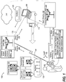
FIG. 1 depicts a block diagram of a communication system of a network utilizing a plurality of evolved Base Nodes (eNBs) for coordinated multi-point (CoMP) communication to a low mobility user equipment (UE) that transmits adaptive data rate and payload feedback of channel state for increased downlink interference nulling. -
FIG. 2 depicts a timing diagram of a methodology for high order spatial channel feedback. -
FIG. 3 depicts a flow diagram of a methodology for adaptive feedback rate and payload. -
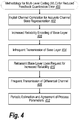
FIG. 4 depicts a flow diagram of an alternative methodology for adaptive feedback rate and payload based upon multi-level coding (MLC). -
FIG. 5 depicts a flow diagram of another alternative methodology for adaptive feedback rate and payload based upon multiple description coding (MDC) using multiple codebooks. -
FIG. 6 depicts a flow diagram of an additional alternative methodology for MDC based upon a fixed codebook. -
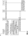
FIG. 7 depicts a flow diagram of a further alternative methodology for adaptive feedback rate and payload for both time and frequency varying codebooks. -
FIG. 8 depicts a multiple access wireless communication system according to one aspect. -
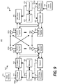
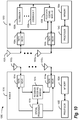
FIG. 9 depicts a block diagram of a communication system. -
FIG. 10 depicts a block diagram of a system for generating and processing channel information feedback in a wireless communication system. -
FIG. 11 depicts a flow diagram of a methodology for coding and communicating channel feedback. -
FIG. 12 depicts a block diagram of a computing platform of UE that supports means for performing adaptive feedback rate and payload. -
FIG. 13 depicts a block diagram of a computing platform of a base node that supports means for receiving adaptive feedback rate and payload. -
FIG. 14 depicts a plot of a simulation that each additional bit of channel state feedback improves interference suppression based on channel coherence. -
FIG. 15 depicts a plot of a simulation for moderate scheduling delay and a reasonable (L1) channel direction information (CDI) payload. -
FIG. 16 depicts a plot of a simulation for averaging observations on a static channel. - In an illustrative context for the present innovation, spatial feedback from user equipment (UE) can be used to reflect channel direction information (CDI) or precoding matrix index (PMI) of various nodes or generally feedback that is quantized. Advantageously, high-rate feedback can be used to provide spatial processing gains for low mobility users. Accordingly to analysis, gains of spatial cooperation for pedestrian UEs (e.g., 1 - 3km/h) can be realized. Such gains cannot be made relying upon message-based (L3) feedback. In a particular exemplary use, there is a need to address spatial codebook design with higher accuracy requirements (e.g., CoMP) compared to the case of multiple input multiple output (MIMO) precoding. Traditional approach to precoding feedback design does not scale well as accuracy requirements increase. By contrast, feedback delivery and scheduling delays limit performance for a high mobility UE (e.g., greater than 10km/h velocity); thus gains through spatial processing are limited for low mobility UEs regardless of feedback accuracy. In particular, for low mobility UEs, channel coherence across subsequent CDI or PMI reports can be exploited.
- Various aspects are now described with reference to the drawings. In the following description, for purposes of explanation, numerous specific details are set forth in order to provide a thorough understanding of one or more aspects. It may be evident, however, that the various aspects may be practiced without these specific details. In other instances, well-known structures and devices are shown in block diagram form in order to facilitate describing these aspects.
- As used in this application, the terms "component", "module", "system", and the like are intended to refer to a computer-related entity, either hardware, a combination of hardware and software, software, or software in execution. For example, a component may be, but is not limited to being, a process running on a processor, a processor, an object, an executable, a thread of execution, a program, and/or a computer. By way of illustration, both an application running on a server and the server can be a component. One or more components may reside within a process and/or thread of execution and a component may be localized on one computer and/or distributed between two or more computers.
- The word "exemplary" is used herein to mean serving as an example, instance, or illustration. Any aspect or design described herein as "exemplary" is not necessarily to be construed as preferred or advantageous over other aspects or designs.
- Furthermore, the one or more versions may be implemented as a method, apparatus, or article of manufacture using standard programming and/or engineering techniques to produce software, firmware, hardware, or any combination thereof to control a computer to implement the disclosed aspects. The term "article of manufacture" (or alternatively, "computer program product") as used herein is intended to encompass a computer program accessible from any computer-readable device, carrier, or media. For example, computer readable media can include but are not limited to magnetic storage devices (e.g., hard disk, floppy disk, magnetic strips...), optical disks (e.g., compact disk (CD), digital versatile disk (DVD)...), smart cards, and flash memory devices (e.g., card, stick). Additionally it should be appreciated that a carrier wave can be employed to carry computer-readable electronic data such as those used in transmitting and receiving electronic mail or in accessing a network such as the Internet or a local area network (LAN). Of course, those skilled in the art will recognize many modifications may be made to this configuration without departing from the scope of the disclosed aspects.
- Various aspects will be presented in terms of systems that may include a number of components, modules, and the like. It is to be understood and appreciated that the various systems may include additional components, modules, etc. and/or may not include all of the components, modules, etc. discussed in connection with the figures. A combination of these approaches may also be used. The various aspects disclosed herein can be performed on electrical devices including devices that utilize touch screen display technologies and/or mouse-and-keyboard type interfaces. Examples of such devices include computers (desktop and mobile), smart phones, personal digital assistants (PDAs), and other electronic devices both wired and wireless.
- Referring initially to
FIG. 1 , acommunication system 100 of a base station, depicted as an evolved base node (eNB) 102, communicates via an over-the-air (OTA) link 104 with user equipment (UE), depicted as a low mobility (e.g., pedestrian-carried)UE 106 and a higher mobility (e.g., vehicle-carried)UE 108. Thehigher mobility UE 108 can be engaged in a conventional multiple input multiple output (MIMO) communication session depicted at 110 with the eNB 102 as well as anothersession 112 with an eNB 114. In order that the eNBs 102, 114 can effectively perform beam shaping depicted respectively at 116, 118 to minimize interference to anotherUE 106, theUE 108 transmitschannel feedback 120. Due to rapid change in location of thehigher mobility UE 108, thisfeedback 120 can have a minimal delay. Thus, in order to not consume OTA resources and processing capability, each spatial feedback transmission is advantageously small in resolution. - By contrast, the
low mobility UE 106 has an opportunity advantageously to transmit higher order spatial channel feedback in order that better interference nulling can be achieved. It should be appreciated thatUE 106 can be capable of performing legacy MIMO transmission such as described forUE 108. In addition, theUE 106 can be responsive to its degree of mobility to enter into a higher order spatial channel feedback mode when appropriate. - For coherent interference that varies little over a particular period of time or over a particular portion of frequency spectra being used (e.g., transmission intervals of time or frequency respectively), the
low mobility UE 106 can advantageously send a higherresolution feedback message 122 for the channel state. In order to not adversely impact the OTA capacity, advantageously thisfeedback 122 can be transmitted in feedback A andfeedback B portions 124, 126, perhaps even at a slower transmission rate as depicted at 128 than thehigher mobility UE 108. These portions of available channel state feedback are combined for enhanced interference nulling by a channelspatial feedback combiner 130 of the eNB 102 for performing enhanced interference nulling depicted as beam shaping 132. - In order to break up this feedback into smaller portions, in an aspect discussed in the aforementioned co-pending application, the
UE 106 can advantageously use one or more of a high orderchannel feedback component 140. In particular, Multiple Level Coding (MLC) component 142 provides for sending a base feedback layer with subsequent enhancement layers. Alternatively or in addition, rather than using the best matching code from a single codebook, a group of N best codes can be cyclically or randomly selected as depicted at 144 so that a situation is avoided where the same low resolution code is repeatedly sent. Alternatively or in addition, multiple codebooks can be used sequentially in order to provide different information, enabling the eNB 102 to work with each code individually or to build up a higher order channel state understanding by combining the codes. - Thereby, the
low mobility UE 106 can engage more effectively in forms of communication that can benefit from enhanced interference nulling, such as network MIMO as depicted at 150 where feedback A,B 152 is also transmitted toeNB 110, which responds in turn with beam shaping as depicted at 154. In an exemplary use, multiple description coding and channel state feedback in network MIMO are used byUE 106 with anetwork 160 enabling coordination between eNB 102, 114. - Advantageously, in using an exemplary MDC approach at both
UEs UEs eNBs 102, 110 of such a change. Instead, theeNBs 102, 110 can determine that a coherent channel across the transmission interval is indicated by the multiple feedback reports, providing an opportunity for combining feedback reports for a more accurate representation of the channel feedback with less quantization error. Alternatively or in addition, theUEs - Downlink coordinated multi-point (CoMP) framework implies cooperative transmission from multiple network nodes (access points, cells or eNBs) to user equipment (UE) or multiple UEs so that inter-node interference is minimized and/or channel gain from multiple nodes is combined at UE receiver. Such cooperative gain and particularly cooperative interference nulling rely upon availability of accurate channel state information at the transmitter (CSIT) of every cooperating node. CSIT feedback is provided in the existing WWAN (Wireless Wide Area Network) air interfaces (e.g. UMB, LTE, WiMax) in a form of precoding direction. Specifically a codebook of precoding vectors (in the case of single spatial stream transmission) and precoding matrices (in the case of single or multi-user MIMO transmission) is used. Each element of the codebook (vector or matrix) corresponds to the 'best' beam (set of beams) corresponding to the downlink channel and UE feeds back index of the best entry based on downlink channel measurements. Typically, precoding feedback is limited to 4-6 bits which is adequate for the existing WWAN systems wherein feedback is optimized for single user (possibly MIMO) transmission and potentially intra-node space division multiple access (SDMA). However, such a design proves to be insufficient in the context of inter-node cooperation for the following reasons.
- In
FIG. 2 , in one aspect amethodology 200 is provided for high order spatial channel feedback from a UE 202 that is used by a plurality ofeNBs network 208 for cooperative transmissions (e.g., CoMP). Inblock 210, UE 202 determines feedback channel state rather than preferred beam direction since the network can be in a better position to determine optimal beam shaping as well as reducing a computational burden on the UE 202. The UE quantizes the feedback (block 212). In an illustrative aspect, thenetwork 208 uses theeNBs nodes - In quantizing channel state information, the UE advantageously makes use of channel coherence to improve feedback accuracy at the network side (block 228). CoMP requires higher feedback accuracy compared to the single user beamforming / MIMO which are the main objectives of the existing WWAN designs. Specifically, feedback needs to be accurate enough to enable interference nulling by a cooperative node or set of nodes. A simple analysis shows that e.g. 6-bit feedback design in a system with 4 transmit antennas and Gaussian IID (independent and identically distributed) channels yields average interference nulling gain on the order of 6dB only and every additional bit improves the achievable interference nulling by about 1dB. Hence a design that aims at 10dB nulling gain would require 10 bits per feedback report which is roughly double of what is currently used. Unlike the existing systems where only feedback relative to a single serving node is needed, in CoMP feedback of the channels between the UE and all cooperative nodes is needed. This fact further drives the overall feedback rate requirements.
- It is, however, important to note that high interference nulling gains can be achieved only for UEs with relatively low mobility. Indeed, medium to high UE mobility on one hand and delay between the time of channel measurement and feedback calculation at UE and the actual downlink transmission by cooperating nodes (referred to as scheduling delay) on the other hand limit achievable nulling gain. This is depicted as determination by the UE at block 230 and recognition of the
network 208 atblock 232 that a high order channel state feedback is being used. A high resolution (low quantization error) feedback from medium-high mobility UEs is therefore less valuable since channel variations caused by scheduling delay limit nulling gains. The key observation here is that high channel feedback accuracy is needed for UEs with relatively low mobility only. Hence it is natural to think of exploiting channel coherence across time to improve feedback accuracy for a given resolution (number of bits per report) on the UE feedback. In the following sections, we highlight a few techniques that achieve this goal. - In
FIG. 3 , amethodology 300 is depicted that advantageously uses adaptive report rate and payload, leveraging an observation that that low mobility UEs do not need to feed back channel state as often as high mobility UEs one hand, depicted as an initial state inblock 302, but low mobility UEs warrant higher feedback accuracy (i.e., to make sure that the latter is not the limiting factor for the achievable nulling gain) on the other hand. Hence a simple approach would consist of slowing down feedback and increasing payload for lower mobility UEs. Thus, inblock 304, the UE determines that it is in a low mobility state. In response, the UE reduces feedback rate and increases feedback payload (block 306). As a specific example, assume that uplink overhead considerations yield 4-bit feedback every 8ms, which is equivalent to a 0.5kbps feedback channel. In this case, one could consider a design where UEs with high(er) mobility feedback a 4-bit report every 8ms while low(er) mobility UEs feedback 8-bit report every 16ms. The obvious drawbacks of this approach are (a) a need to tune report format to UE mobility which implies either explicit communication (handshake) between the UE and the network or additional bits to indicate the format (block 308) as well as impacts due to (b) increased feedback delay (8ms to 16ms) that limits nulling gains. - Alternatively, the network can recognize the low mobility of the UE and can anticipate receiving high order feedback without additional handshaking or signaling. As a further alternative, in some implementations the UE can increase feedback accuracy in a low mobility state without necessarily reducing the feedback rate in proportion or at all.
- In
FIG. 4 , an alternative approach to achieving high order feedback (e.g., reduced quantization errors) is depicted as a methodology 400 for Multi-Level Coding (MLC). Multi-level coding principle is widely used in source coding, namely speech, audio and video coding. The basic idea of multi-level coding is to exploit channel correlation to achieve the most accurate representation for a given payload size (block 402). Practically speaking, multi-level coding implies periodic infrequent feedback of the full quantized channel (usually called base layer) (block 404) and more frequent feedback of 'differential channel' or 'innovation' (block 406). The higher channel correlation across time the better feedback accuracy can be achieved with a given number of bits. Multi-level coding arguably provides the best accuracy for a given payload size. There is however a number of drawbacks to this approach. First of all, base layer needs to be sent with higher reliability than enhancement layer as the loss of base layer means loss of feedback until base layer is retransmitted (block 408). This also implies that base layer should be transmitted fairly often and/or explicit signaling is needed from the network to UE to request retransmission of the base layer (block 410). Second, multi-level coding gain depends on the accuracy of process modeling (i.e. approximation of channel correlation across time). Hence process parameters need to be periodically estimated and agreed upon between the UE and the network, depicted at 412. Finally, implementing multi-level coding implies multiple changes to the feedback structure at PHY/MAC level as well as additional signaling to communicate feedback format, (correlation) parameters etc. - In
FIG. 5 , an exemplary alternative for increased feedback accuracy is depicted as amethodology 500 for Multiple Description Coding (MDC). The general idea of multiple description coding consists of using multiple code descriptions to improve the accuracy of the source representation at the receiver. In the present context of channel state feedback, this could be implemented by e.g. using different codebooks with the same statistical properties at different time instances (block 502). To illustrate this concept, let's assume a static or low mobility (time-invariant) channel (block 504). In the existing WWAN systems, constant (time invariant) codebook is used hence UE would feed exactly the same precoding index to the network at every time instance assuming accurate channel state estimation at the receiver. Hence multiple consecutive feedback reports do not provide and additional information and channel state estimation at the network is defined by quantization accuracy (payload) size of a single feedback instance. Now assume that a time varying codebook is used. In the latter case, every instance of channel feedback refers to an entry from a different codebook hence yielding a different precoding matrix or vector (block 506). Instead of obtaining exactly the same information regarding channel state on different reports (as in fixed codebook case), the network gets different 'looks' at the channel state (block 508). Based on the network assessment of low UE mobility (block 510), the network may choose to suitably combine these reports to improve the accuracy of channel state as compared to a single report from a fixed codebook (block 511). - Various specific ways of how to combine multiple reports may be considered depending on the type of channel state feedback. The two 'typical' examples are full channel feedback (block 512) and Eigen-direction feedback (block 514). In the former case, optimal combining may be achieved through linear (e.g., minimum means squared error (MMSE)) filtering of channel state feedback corresponding to different instances with the proper choice of filter parameters consistent with UE mobility, assuming that channel state is a Gaussian process (block 516). In the case of Eigen-direction feedback, optimal solution is not straightforward but some heuristics can be used (block 518). For instance, channel state estimate can be obtained as the principal component of a non-negative Hermitian matrix computed as a weighted sum of outer auto-products of channel states received at different instances with the proper choice of weighting profile consistent with UE mobility (block 520). Alternatively, the combination can be performed by MMSE (block 521).
- Now let us consider a mobile UE such that channel state is fully uncorrelated between the adjacent reports (block 522). While the same time-varying codebook can be used, the network will use the most recent report from the UE to estimate channel state (block 524). Since every codebook in the time varying sequence has the same statistical properties as a fixed codebook, channel state feedback accuracy with a time-varying codebooks will be no different compared to the case of a fixed codebook. Hence the same sequence of codebooks can be used regardless of UE mobility.
- Based on the above facts and further obvious observations, we can summarize some useful properties of multiple description coding (MDC) based on time-varying codebook design:
- First, time varying codebook does not depend on UE mobility and channel variation statistics. Hence a single sequence of codebooks can be used to replace a single codebook. The length of this sequence is defined by the maximum number of reports considered for combining. As increase in combining gain reduces along with the number of combined reports even at relatively low mobility, practical sequence length can be limited to single digit or low double digit numbers. Once sequence length is fixed, this sequence can be re-used (e.g., in a round robin fashion).
- Second, for a 'sensible' UE implementation, no additional complexity at the UE is incurred due to time varying codebook compared to a fixed one. Indeed, UE computes precoding feedback for a given codebook based on the best match of channel estimate across all entries of the codebook. In the case of time invariant codebook, matching is performed with respect to the same codebook while in the case of time varying codebook matching with respect to different codebooks is performed at different time instances. Note that memory requirements will not be large if time varying sequence has limited size while performance gain even with 2-4 codebooks turns to be substantial. Also note that fairly good codebooks can be generated in a pseudo-random fashion (based on a pre-determined low-complexity algorithm seeded by a number) in which case there would be no additional memory requirements and there is no need/reason to limit sequence length to a small number.
- Third, combining of multiple reports is optional at the network. As explained before in the case of time varying channel, the network can use the most recent report only from the UE thereby achieving the same feedback accuracy as the standard fixed codebook design. A 'lazy' network implementation would use the most recent report regardless of UE mobility and hence will achieve performance/complexity tradeoff that is achievable with a fixed codebook. Meanwhile, a 'smart' network implementation could combine multiple reports based on UE mobility estimated at the network.
- Fourth, every instance of feedback can have the same format and reliability requirements yielding a homogeneous control signaling (PHY/MAC) design. In the context of 3GPP LTE evolution (LTE-Advanced), it may be possible to reuse the existing UE feedback format defined in LTE Rel-8 based on PUCCH. Furthermore, as already mentioned, codebook structure does not depend on UE mobility hence there is no need for additional periodic signaling between the UE and the network to synch-up on feedback format and parameters (unlike in the case of adaptive report rate/payload or multi-level coding).
- Note that multiple description coding principle can be applied in the case of a fixed codebook as well. Instead of feeding back the index of the best matching precoding entry, a low mobility UE could feed back in a round-robin fashion its N best entries. Performance gain of this solution remains non-negligible for low-mobility UEs so long N is relatively small although it is certainly less than performance gain obtained when the best precoding entry is reported at every instance and a time varying codebook is used. Another clear drawback of this approach is that N needs to be updated according to UE channel conditions since using N> 1 is clearly detrimental for high mobility UEs where no combining is possible. Updating N means additional signaling between the UE and the network which is also undesirable.
- Thus, in
FIG. 6 , as a further alternative for increased feedback accuracy, a methodology 600 is depicted wherein a single codebook is used. In particular, it is recognized that the best representation from the codebook can be repetitively sent if the channel state is coherent. Thus, the network gains no additional insight into the channel state by such repetitively sent feedback. For a codebook of sufficient size, a plurality of N representations can be selected as a group that are the "best" and randomly or cyclically sent such that the network can combine these representations to realize a more accurate representation of the channel state. To that end, inblock 602, the UE measures the channel state. A codebook is accessed (block 604) and a plurality of N representation codes are selected as most closely approximating the channel state (block 606). One of the codes is selected (e.g., rank ordered as best, randomly selected, sequentially selected) (block 608) A determination is made as to whether this was the code sent during the late feedback transmission (block 610). If so, processing returns to block 608 to select another code. If appropriate inblock 610, then the selected code is sent (block 612). At the network, the series of codes are recognized as being directed to an essentially coherent channel, enabling a combination of the code representations to achieve a more accurate representation (block 614). Based upon this determination, improved interference nulling can be performed by appropriate cooperative beamforming (block 616). - Returning to observations regarding multiple description coding, fifth, the described multiple description coding principle can be applied in the context of frequency coherence as well. In
FIG. 7 , amethodology 700 is depicted for taking advantage of frequency coherence for higher accuracy in channel state feedback. By using frequency varying codebook (e.g. different codebooks corresponding to different sub bands) (block 702), we can improve channel state accuracy for channels with a good coherence in the frequency domain, hence moderate frequency selectivity. In a more general setting, one should consider time and frequency varying codebook design where channel state quantization within a given time instance (e.g. sub-frame) and a given sub band is performed according to a codebook associated with this slot/sub band pair (block 704). The network can further combine reports corresponding to different time instances and sub bands based on the estimated time/frequency coherence of the underlying channel (block 706). - Generally, a wireless multiple-access communication system can simultaneously support communication for multiple wireless terminals. Each terminal communicates with one or more base stations via transmissions on the forward and reverse links. The forward link (or downlink) refers to the communication link from the base stations to the terminals, and the reverse link (or uplink) refers to the communication link from the terminals to the base stations. This communication link may be established via a single-in-single-out, multiple-in-signal-out or a multiple-in-multiple-out (MIMO) system.
- A MIMO system employs multiple (NT ) transmit antennas and multiple (NR ) receive antennas for data transmission. A MIMO channel formed by the NT transmit and NR receive antennas may be decomposed into NS independent channels, which are also referred to as spatial channels, where NS ≤ min{NT , NR }. Each of the NS independent channels corresponds to a dimension. The MIMO system can provide improved performance (e.g., higher throughput and/or greater reliability) if the additional dimensionalities created by the multiple transmit and receive antennas are utilized.
- A MIMO system supports a time division duplex (TDD) and frequency division duplex (FDD) systems. In a TDD system, the forward and reverse link transmissions are on the same frequency region so that the reciprocity principle allows the estimation of the forward link channel from the reverse link channel. This enables the access point to extract transmit beamforming gain on the forward link when multiple antennas are available at the access point.
- Referring to
FIG. 8 , a multiple access wireless communication system according to one aspect is illustrated. An access point 850 (AP) includes multiple antenna groups, one including 854 and 856, another including 858 and 860, and an additional including 862 and 864. InFIG. 8 , only two antennas are shown for each antenna group, however, more or fewer antennas may be utilized for each antenna group. Access terminal (AT) 866 is in communication withantennas antennas forward link 870 and receive information fromaccess terminal 866 overreverse link 868.Access terminal 872 is in communication withantennas antennas forward link 876 and receive information fromaccess terminal 872 overreverse link 874. In a FDD system,communication links forward link 870 may use a different frequency then that used byreverse link 868. Each group of antennas and/or the area in which they are designed to communicate is often referred to as a sector of theaccess point 850. In the aspect, antenna groups each are designed to communicate to accessterminals access point 850. - In communication over
forward links access point 850 utilize beamforming in order to improve the signal-to-noise ratio of forward links for thedifferent access terminals - An
access point 850 may be a fixed station used for communicating with the terminals and may also be referred to as an access point, a Node B, or some other terminology. Anaccess terminal -
FIG. 5 is a block diagram of an aspect of a transmitter system 910 (also known as the access point) and a receiver system 950 (also known as access terminal) in aMIMO system 900. At thetransmitter system 910, traffic data for a number of data streams is provided from a data source 912 to a transmit (TX)data processor 914. - In an aspect, each data stream is transmitted over a respective transmit antenna.
TX data processor 914 formats, codes, and interleaves the traffic data for each data stream based on a particular coding scheme selected for that data stream to provide coded data. - The coded data for each data stream may be multiplexed with pilot data using OFDM techniques. The pilot data is typically a known data pattern that is processed in a known manner and may be used at the receiver system to estimate the channel response. The multiplexed pilot and coded data for each data stream is then modulated (i.e., symbol mapped) based on a particular modulation scheme (e.g., BPSK, QSPK, M-PSK, or M-QAM) selected for that data stream to provide modulation symbols. The data rate, coding, and modulation for each data stream may be determined by instructions performed by
processor 930. - The modulation symbols for all data streams are then provided to a
TX MIMO processor 920, which may further process the modulation symbols (e.g., for OFDM).TX MIMO processor 920 then provides NT modulation symbol streams to NT transmitters (TMTR) 922a through 922t. In certain implementations,TX MIMO processor 920 applies beamforming weights to the symbols of the data streams and to the antenna from which the symbol is being transmitted. - Each transmitter 922 receives and processes a respective symbol stream to provide one or more analog signals, and further conditions (e.g., amplifies, filters, and upconverts) the analog signals to provide a modulated signal suitable for transmission over the MIMO channel. NT modulated signals from
transmitters 922a through 922t are then transmitted from NT antennas 924a through 924t, respectively. - At
receiver system 950, the transmitted modulated signals are received by NR antennas 952a through 952r and the received signal from each antenna 952 is provided to a respective receiver (RCVR) 954a through 954r. Each receiver 954 conditions (e.g., filters, amplifies, and downconverts) a respective received signal, digitizes the conditioned signal to provide samples, and further processes the samples to provide a corresponding "received" symbol stream. - An
RX data processor 960 then receives and processes the NR received symbol streams from NR receivers 954 based on a particular receiver processing technique to provide NT "detected" symbol streams. TheRX data processor 960 then demodulates, deinterleaves, and decodes each detected symbol stream to recover the traffic data for the data stream. The processing byRX data processor 960 is complementary to that performed byTX MIMO processor 920 andTX data processor 914 attransmitter system 910. - A
processor 970 periodically determines which pre-coding matrix to use (discussed below).Processor 970 formulates a reverse link message comprising a matrix index portion and a rank value portion. - The reverse link message may comprise various types of information regarding the communication link and/or the received data stream. The reverse link message is then processed by a
TX data processor 938, which also receives traffic data for a number of data streams from adata source 936, modulated by amodulator 980, conditioned bytransmitters 954a through 954r, and transmitted back totransmitter system 910. - At
transmitter system 910, the modulated signals fromreceiver system 950 are received by antennas 924, conditioned by receivers 922, demodulated by ademodulator 940, and processed by aRX data processor 942 to extract the reserve link message transmitted by thereceiver system 950.Processor 930 then determines which pre-coding matrix to use for determining the beamforming weights then processes the extracted message. - In an aspect, logical channels are classified into Control Channels and Traffic Channels. Logical Control Channels comprises Broadcast Control Channel (BCCH), which is DL channel for broadcasting system control information. Paging Control Channel (PCCH), which is DL channel that transfers paging information. Multicast Control Channel (MCCH) which is Point-to-multipoint DL channel used for transmitting Multimedia Broadcast and Multicast Service (MBMS) scheduling and control information for one or several MTCHs. Generally, after establishing RRC connection this channel is only used by UEs that receive MBMS (Note: old MCCH+MSCH). Dedicated Control Channel (DCCH) is Point-to-point bi-directional channel that transmits dedicated control information and used by UEs having an RRC connection. In aspect, Logical Traffic Channels comprises a Dedicated Traffic Channel (DTCH), which is Point-to-point bi-directional channel, dedicated to one UE, for the transfer of user information. In addition, a Multicast Traffic Channel (MTCH) for Point-to-multipoint DL channel for transmitting traffic data.
- In an aspect, Transport Channels are classified into DL and UL. DL Transport Channels comprises a Broadcast Channel (BCH), Downlink Shared Data Channel (DL-SDCH) and a Paging Channel (PCH), the PCH for support of UE power saving (DRX cycle is indicated by the network to the UE), broadcasted over entire cell and mapped to PHY resources which can be used for other control/traffic channels. The UL Transport Channels comprises a Random Access Channel (RACH), a Request Channel (REQCH), an Uplink Shared Data Channel (UL-SDCH) and plurality of PHY channels. The PHY channels comprise a set of DL channels and UL channels.
- The DL PHY channels comprises: Common Pilot Channel (CPICH); Synchronization Channel (SCH); Common Control Channel (CCCH); Shared DL Control Channel (SDCCH); Multicast Control Channel (MCCH); Shared UL Assignment Channel (SUACH); Acknowledgement Channel (ACKCH); DL Physical Shared Data Channel (DL-PSDCH); UL Power Control Channel (UPCCH); Paging Indicator Channel (PICH); Load Indicator Channel (LICH); The UL PHY Channels comprises: Physical Random Access Channel (PRACH); Channel Quality Indicator Channel (CQICH); Acknowledgement Channel (ACKCH); Antenna Subset Indicator Channel (ASICH); Shared Request Channel (SREQCH); UL Physical Shared Data Channel (UL-PSDCH); Broadband Pilot Channel (BPICH).
- In an aspect, a channel structure is provided that preserves low PAR (at any given time, the channel is contiguous or uniformly spaced in frequency) properties of a single carrier waveform.
- For the purposes of the present document, the following abbreviations apply:
- AIS
- Automatic Identification System
- AM
- Acknowledged Mode
- AMD
- Acknowledged Mode Data
- ARQ
- Automatic Repeat Request
- BCCH
- Broadcast Control CHannel
- BCH
- Broadcast CHannel
- C-
- Control-
- CCCH
- Common Control CHannel
- CCH
- Control CHannel
- CCTrCH
- Coded Composite Transport Channel
- CDI
- Channel Direction Information
- CP
- Cyclic Prefix
- CRC
- Cyclic Redundancy Check
- CTCH
- Common Traffic CHannel
- DCCH
- Dedicated Control CHannel
- DCH
- Dedicated CHannel
- DL
- DownLink
- DSCH
- Downlink Shared CHannel
- DTCH
- Dedicated Traffic CHannel
- FACH
- Forward link Access CHannel
- FDD
- Frequency Division Duplex
- i.i.d.
- independent and identically distributed
- LI
- Layer 1 (physical layer)
- L2
- Layer 2 (data link layer)
- L3
- Layer 3 (network layer)
- LI
- Length Indicator
- LSB
- Least Significant Bit
- MAC
- Medium Access Control
- MBMS
- Multimedia Broadcast Multicast Service
- MCCH
- MBMS point-to-multipoint Control CHannel
- MIMO
- Multiple Input Multiple Output
- MRW
- Move Receiving Window
- MSB
- Most Significant Bit
- MSCH
- MBMS point-to-multipoint Scheduling CHannel
- MTCH
- MBMS point-to-multipoint Traffic CHannel
- PCCH
- Paging Control CHannel
- PCH
- Paging CHannel
- PDU
- Protocol Data Unit
- PHY
- PHYsical layer
- PhyCH
- Physical CHannels
- QoS
- Quality of Service
- RACH
- Random Access CHannel
- RLC
- Radio Link Control
- RRC
- Radio Resource Control
- SAP
- Service Access Point
- SDU
- Service Data Unit
- SHCCH
- SHared channel Control CHannel
- SN
- Sequence Number
- SUFI
- SUper FIeld
- TCH
- Traffic CHannel
- TDD
- Time Division Duplex
- TFI
- Transport Format Indicator
- TM
- Transparent Mode
- TMD
- Transparent Mode Data
- TTI
- Transmission Time Interval
- U-
- User-
- UE
- User Equipment
- UL
- UpLink
- UM
- Unacknowledged Mode
- UMB
- Ultra Mobile Broadband
- UMD
- Unacknowledged Mode Data
- UMTS
- Universal Mobile Telecommunications System
- UTRA
- UMTS Terrestrial Radio Access
- UTRAN
- UMTS Terrestrial Radio Access Network
- WWAN
- Wireless Wide Area Network
- Turning to
FIG. 10 , a block diagram of asystem 1000 for generating and processing channel information feedback in a wireless communication system is illustrated.System 1000 can include one ormore Node Bs 1010 and one ormore UEs 1030, which can communicate via respective antennas 1012 and 1032. In one example,UE 1030 can provide spatial feedback toNode B 1010, which can be utilized byNode B 1010 to ascertain CDI of various network nodes and perform spatial processing. Alternatively, precoding matrix index (PMI) can be the form of feedback. CDI represents the actual channel (or a normalized channel) between the network (eNB) and the UE while PMI represents a precoder (beam) suggested by the UE to the eNB based on channel measurements performed as the UE. - In one aspect,
UE 1030 can include afeedback coding module 1038, which can generate and/or otherwise identify channel state information (e.g., spatial feedback information) for transmission toNode B 1010. In one example,feedback coding module 1038 can utilize multiple description coding to encode spatial feedback information as described herein to generate a series of streams for spatial feedback that can be communicated from transceiver(s) 1034 and antenna(s) 1032 toNode B 1010. For example,feedback coding module 1038 can utilize a set of codebooks 1036 to encode respective streams. In an aspect, codebooks 1036 can be configured with substantially similar properties and can be configured to vary in time, frequency, and/or any other suitable interval. Spatial feedback streams can then be received atNode B 1010 via antenna(s) 1012 and transceiver(s) 1014. Upon receipt of the spatial feedback atNode B 1010, afeedback decoding module 1016 and/or aspatial processor 1018 can be utilized to obtain a channel estimate corresponding toUE 1030, based on which transmissions toUE 1030 can be adjusted. By utilizing multiple description coding in the described manner, it can be appreciated that the interference suppression performance ofsystem 1000 can be increased without requiring an increase in spatial codebook size. - In another aspect, multiple description coding as described herein can be performed in a manner that is transparent to
UE 1030 without requiring changes in the processing and/or reporting rules utilized byUE 1030. In one example,feedback decoding module 1016 and/orspatial processor 1018 atNode B 1010 can extrapolate spatial feedback information corresponding to aUE 1030 from past reports from theUE 1030 in order to compress errors. - As
FIG. 10 illustrates,Node B 1010 can additionally utilize aprocessor 1022 and/ormemory 1024 to implement the above functionality and/or other suitable functionality. Similarly,UE 1030 can include aprocessor 1042 and/or amemory 1044 that can be utilized to implement the above functionality and/or other suitable functionality. -
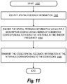
FIG. 11 illustrates amethodology 1100 for coding and communicating channel feedback. Atblock 1102, spatial feedback information is identified. At block 1104, the spatial feedback information is encoded via multiple description coding using a series of codebooks corresponding to respective intervals in time and/or frequency. Atblock 1106, the coded spatial feedback information is transmitted at the intervals corresponding to the codebooks. - In
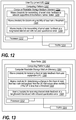
FIG. 12 , user equipment (UE) 1200 has a computing platform 1202 that provides means such as sets of codes for causing a computer to perform adaptive feedback rate and payload for more accurate channel state information at the transmitter. In particular, the computing platform 1202 includes a computer readable storage medium (e.g., memory) 1204 that stores a plurality of modules 1206-1210 executed by a processor(s) 1212, which also controls a transmitter/receiver component 1214 for communicating with eNBs (FIG. 13 ). In particular, a means (module) 1206 is provided for transmitting channel state feedback to a network in a manner supportive of incoherent channel states. A means (module) 1208 is provided for determining mobility of less than a threshold (i.e., a low mobility state that warrants increasing feedback accuracy perhaps with reduced frequency of transmission). A means (module) 1210 is provided for transmitting channel state feedback at a lengthened interval and with reduced quantization error. - In
FIG. 13 , evolved base node (eNB) 1300 has acomputing platform 1302 that provides means such as sets of codes for causing a computer to receive and use adaptive feedback rate and payload for more accurate channel state information at the transmitter. In particular, thecomputing platform 1302 includes a computer readable storage medium (e.g., memory) 1304 that stores a plurality of modules 1306-1310 executed by a processor(s) 1312, which also controls a transmitter/receiver component 1314 for communicating with UE (FIG. 12 ). In particular, a means (module) 1306 is provided for receiving channel state feedback from user equipment (UE). A means (module) 1308 is provided for determining a change in the channel state feedback rate and payload from the UE that occurs when mobility of the UE is less than a threshold. A means (module) 1310 is provided for receiving channel state feedback at a lengthened interval and with reduced quantization error. - With regard to codebook performance metric, assume frequency flat channel between MTX TX (transmit) antennas & one RX (receiving) antenna. Consider extensions to frequency selective channels via channel expansion in a suitable basis, quantization of the expansion coefficients and subsequent reconstruction. Suitable basis could be quantization of "flat" channels from different sub-bands, time domain (tap) quantization, etc. Codebook performance can be defined in terms of the distribution tail of the maximum correlation of a channel with the best codeword. Thus, consider a codebook (C) defined


B . As a rationale, consider for a static channel h, a beamforming vector that is chosen orthogonal to the reported CDI guarantees interference suppression with probability not less than (1-α) of at least

- Performance of a random codebook can be assessed analytically for a family of complex circular Gaussian channels. Consider only the case of i.i.d. (independent and identically distributed) channel h although extension to correlated channels is possible. Random codebook C is generated as a set of i.i.d. complex circular Gaussian channels normalized to a unit norm


interference suppression 
- Regarding, an empirical relationship based on optimized codebooks, select the best of 103 randomly chosen codebooks, estimated

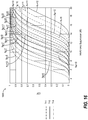
FIG. 14 . - Further, assume ideal quantization and consider suppression level caused by channel de-correlation due to mobility. Focusing on low mobility (pedestrian) UEs and assume first order interpolation, better results are achievable with a reasonably matched higher-order model. As depicted in
FIG. 15 at 1500, for pedestrian UEs, moderate scheduling delay and a reasonable (L1) CDI payload: channel feedback is a limiting factor, given velocity 1-3 km/h, scheduling delay ≤ 10ms, CDI payload ≤ 12 bits. - As a high level approaches to the problem, one can tune reporting rate and payload size to channel variability. Update report format (resolution) can be adapted to UE mobility. In an exemplary approach, there can be a likely need to split payload over multiple reports due to higher erasure rate.
- One option for achieving higher resolution, multi-level coding (MLC) can be used. MLC can require periodic reliable update of variation model parameters. There can be different reliability requirements for base and enhancement layers of the MLC. For instance, it can be of highest importance that a base layer is received in order to have meaningful information whereas a subsequent enhancement layer can be missed without serious degradation in achieving interference nulling based upon spatial feedback. One consideration for MLC is that higher complexity at UE can be required to generate the MLC spatial channel feedback.
- As an alternative, multiple description coding (MDC) can be used. An exemplary implementation introduces multiple codebooks with the same properties for transmission interval (e.g., time-varying or frequency-varying) codebooks. Advantageously, such MDC implementation does not impose a change in processing or reporting rules at UE. Further, a "lazy eNB" can use instantaneous reports without having to combine MDC reports for a higher resolution spatial channel feedback, thus requiring no change with respect to a baseline. However, a "smart" eNB can extrapolate from past reports to compress errors.
- As an illustrative analysis, consider a static channel case. Assume static flat channel between MTX TX antennas and one 1 RX antenna. Assume that T different codebooks C (1), ..., C (T) are used across T intervals and UE feeds back indices l 1, ..., lN. A plausible channel estimate to use is given by the dominant principal component of matrix

FIG. 16 at 1600. - With regard to analyzing time-selective channels, consider time variations according to Jakes model with different speeds. Time varying codebooks are assumed. As an extension of the combined estimator, search for the principal component of a matrix

- Several observations can be made in summary. Accounting for channel coherence across time is equivalent to a non-trivial increase in feedback payload size. The same applies to frequency domain variability as another form of a transmission interval. Potential solutions include adapting payload size and reporting rate to UE mobility, which can require explicit dynamic signaling to change reporting format. Alternatively, multi-level coding can be used, which can require explicit signaling and parameter tuning with non-uniform error protection. As yet another alternative, a plurality of nearly optimal codes can be used cyclically from the same codebook rather than continually sending the same code. As an exemplary alternative, multiple description coding via time (or frequency) varying codebooks can be used, which is transparent to UE, achieves gains based on eNB algorithm with no robustness issues as well as requiring minimal changes to AIS and UE implementation.
- It is understood that the specific order or hierarchy of steps in the processes disclosed is an example of exemplary approaches. Based upon design preferences, it is understood that the specific order or hierarchy of steps in the processes may be rearranged while remaining within the scope of the present disclosure. The accompanying method claims present elements of the various steps in a sample order, and are not meant to be limited to the specific order or hierarchy presented.
- It should be appreciated for clarity that the illustrative aspects described herein focus on UE encoding spatial feedback to an eNB. However, applications consistent with aspects herein can be made to uplink (UL) traffic transmission with UL precoding (CoMP) wherein UE is forming beams based on feedback from the network (e.g., eNB). Thus, the roles of the UE and eNB change places with respect to increasing feedback accuracy.
- It should be appreciated with the benefit of the present disclosure that MDC principles can be applied to any other type of feedback where quantized quantity exhibits correlation in time and/or frequency. As a specific example, we should use CQI reporting (which could be a broadband CQI and/or sub band specific CQI). Conventionally, a CQI would be quantized with a fixed table wherein every value of the payload would map to a certain C/I or rate (spectral efficiency) value. Instead, we could use time-varying tables thereby achieving MDC gains in a low mobility.
- Those of skill in the art would understand that information and signals may be represented using any of a variety of different technologies and techniques. For example, data, instructions, commands, information, signals, bits, symbols, and chips that may be referenced throughout the above description may be represented by voltages, currents, electromagnetic waves, magnetic fields or particles, optical fields or particles, or any combination thereof.
- Those of skill would further appreciate that the various illustrative logical blocks, modules, circuits, and algorithm steps described in connection with the embodiments disclosed herein may be implemented as electronic hardware, computer software, or combinations of both. To clearly illustrate this interchangeability of hardware and software, various illustrative components, blocks, modules, circuits, and steps have been described above generally in terms of their functionality. Whether such functionality is implemented as hardware or software depends upon the particular application and design constraints imposed on the overall system. Skilled artisans may implement the described functionality in varying ways for each particular application, but such implementation decisions should not be interpreted as causing a departure from the scope of the present disclosure.
- The various illustrative logical blocks, modules, and circuits described in connection with the embodiments disclosed herein may be implemented or performed with a general purpose processor, a digital signal processor (DSP), an application specific integrated circuit (ASIC), a field programmable gate array (FPGA) or other programmable logic device, discrete gate or transistor logic, discrete hardware components, or any combination thereof designed to perform the functions described herein. A general purpose processor may be a microprocessor, but in the alternative, the processor may be any conventional processor, controller, microcontroller, or state machine. A processor may also be implemented as a combination of computing devices, e.g., a combination of a DSP and a microprocessor, a plurality of microprocessors, one or more microprocessors in conjunction with a DSP core, or any other such configuration.
- The steps of a method or algorithm described in connection with the embodiments disclosed herein may be embodied directly in hardware, in a software module executed by a processor, or in a combination of the two. A software module may reside in RAM memory, flash memory, ROM memory, EPROM memory, EEPROM memory, registers, hard disk, a removable disk, a CD-ROM, or any other form of storage medium known in the art. An exemplary storage medium is coupled to the processor such the processor can read information from, and write information to, the storage medium. In the alternative, the storage medium may be integral to the processor. The processor and the storage medium may reside in an ASIC. The ASIC may reside in a user terminal. In the alternative, the processor and the storage medium may reside as discrete components in a user terminal.
- The previous description of the disclosed embodiments is provided to enable any person skilled in the art to make or use the present disclosure. Various modifications to these embodiments will be readily apparent to those skilled in the art, and the generic principles defined herein may be applied to other embodiments without departing from the spirit or scope of the disclosure. Thus, the present disclosure is not intended to be limited to the embodiments shown herein but is to be accorded the widest scope consistent with the principles and novel features disclosed herein.
- In view of the exemplary systems described supra, methodologies that may be implemented in accordance with the disclosed subject matter have been described with reference to several flow diagrams. While for purposes of simplicity of explanation, the methodologies are shown and described as a series of blocks, it is to be understood and appreciated that the claimed subject matter is not limited by the order of the blocks, as some blocks may occur in different orders and/or concurrently with other blocks from what is depicted and described herein. Moreover, not all illustrated blocks may be required to implement the methodologies described herein. Additionally, it should be further appreciated that the methodologies disclosed herein are capable of being stored on an article of manufacture to facilitate transporting and transferring such methodologies to computers. The term article of manufacture, as used herein, is intended to encompass a computer program accessible from any computer-readable device, carrier, or media.
Claims (15)
- A method for wirelessly transmitting channel state feedback, comprising:measuring a wireless channel (104); transmitting the channel state feedback; further characterized by reducing quantization error of channel state feedback reports by encoding the channel state feedback as multiple description coding by using multiple code descriptions wherein a different code is selected based upon a transmission interval.
- The method of claim 1, further comprising:encoding the channel state feedback using a plurality of codebooks that correspond to and vary with respective transmission intervals; andtransmitting the encoded channel state feedback at the respective transmission intervals,in particular wherein the transmission intervals are time intervals, or wherein the transmission intervals are frequency intervals, orwherein the transmission intervals are both time-based frames and frequency sub bands.
- The method of claim 1, further comprising sending sequentially one of a plurality of best code representations from a single codebook in response to invariant channel state feedback.
- The method of claim 1, further comprising measuring channel quality indication, CQI, feedback or measuring precoding matrix index, PMI, feedback.
- An apparatus (1200) for wirelessly transmitting channel state feedback, comprising:means for measuring a wireless channel (104) means (1206, 1208) for transmitting the channel state feedback;characterized bymeans for reducing quantization error of channel state feedback reports by encoding the channel state feedback as multiple description coding by using multiple code descriptions wherein a different code is selected based upon a transmission interval.
- The apparatus (1200) of claim 5, wherein
the means for measuring the wireless channel is a receiver;
the means for reducing quantization error is a computing platform; and the means (1206, 1208) for transmitting is a transmitter,
wherein the computing platform is further for encoding the channel state feedback using a plurality of codebooks that correspond to and vary with respective transmission intervals, and wherein the transmitter is further for transmitting the encoded channel state feedback at the respective transmission intervals. - The apparatus (1200) of claim 6, wherein the transmission intervals are time intervals, frequency intervals or both time-based frames and frequency sub bands.
- A method for wirelessly receiving channel state feedback, comprising:receiving a plurality of channel state feedback reports;determining a coherent channel across the plurality of transmission intervals;characterized bydecoding multiple description coding of the channel state feedback reports that use multiple code descriptions over a plurality of transmission intervals in which different codes were selected based upon the respective transmission interval; andcombining the plurality of channel state feedback reports for increased channel state feedback accuracy for a coherent channel across the transmission intervals.
- The method of claim 8, further comprising:detecting incoherence of the channel across a second plurality of channel state feedback reports; anddetermining channel state based upon individual channel state feedback reports for the second plurality of channel state feedback reports.
- The method of claim 8, further comprising decoding channel state feedback reports based upon a plurality of codebooks that correspond to and vary with respective transmission intervals.
- A computer-readable storage medium comprising code to perform the steps of the method according to any one of the claims 1 to 4 or 8 to 10 when executed on a computer.
- An apparatus (1300) for wirelessly receiving channel state feedback, comprising:means (1306, 308) for receiving a plurality of channel state feedback reports; means for determining a coherent channel across the plurality of transmission intervals;characterized bymeans for decoding multiple description coding of the channel state feedback reports over a plurality of transmission intervals in which different codes were selected based upon the respective transmission interval; andmeans for combining a plurality of channel state feedback reports for increased channel state feedback accuracy for a coherent channel across transmission intervals.
- The apparatus (1300) of claim 12, wherein
the means (1306, 1308) for receiving is a receiver; and
the means for decoding, the means for determining and the means for combining is a computing platform,
wherein the computing platform is further for detecting incoherence of the channel across a plurality of channel state feedback reports and for determining channel state based upon a single channel state feedback report. - The apparatus (1300) of claim 13, wherein the transmission intervals are time intervals, frequency intervals or both time-based frames and frequency sub bands.
- A computer program comprising instructions to perform the steps of the method according to any of the claims 1 to 4 or 8 to 10 when executed on a computer.
Applications Claiming Priority (3)
| Application Number | Priority Date | Filing Date | Title |
|---|---|---|---|
| US10446508P | 2008-10-10 | 2008-10-10 | |
| US12/348,827 US8983397B2 (en) | 2008-10-10 | 2009-01-05 | Method and apparatus for channel feedback by multiple description coding in a wireless communication system |
| PCT/US2009/030230 WO2010042234A1 (en) | 2008-10-10 | 2009-01-06 | Method and apparatus for channel feedback by multiple description coding in a wireless communication system |
Publications (2)
| Publication Number | Publication Date |
|---|---|
| EP2345190A1 EP2345190A1 (en) | 2011-07-20 |
| EP2345190B1 true EP2345190B1 (en) | 2017-09-13 |
Family
ID=42098830
Family Applications (2)
| Application Number | Title | Priority Date | Filing Date |
|---|---|---|---|
| EP09789409A Withdrawn EP2345187A1 (en) | 2008-10-10 | 2009-01-06 | Method and apparatus for channel feedback in a wireless communication system |
| EP09789408.3A Active EP2345190B1 (en) | 2008-10-10 | 2009-01-06 | Method and apparatus for channel feedback by multiple description coding in a wireless communication system |
Family Applications Before (1)
| Application Number | Title | Priority Date | Filing Date |
|---|---|---|---|
| EP09789409A Withdrawn EP2345187A1 (en) | 2008-10-10 | 2009-01-06 | Method and apparatus for channel feedback in a wireless communication system |
Country Status (8)
| Country | Link |
|---|---|
| US (3) | US8644408B2 (en) |
| EP (2) | EP2345187A1 (en) |
| JP (3) | JP5680540B2 (en) |
| KR (2) | KR101433278B1 (en) |
| CN (2) | CN102177670B (en) |
| BR (1) | BRPI0919784A2 (en) |
| TW (2) | TW201015931A (en) |
| WO (2) | WO2010042234A1 (en) |
Families Citing this family (97)
| Publication number | Priority date | Publication date | Assignee | Title |
|---|---|---|---|---|
| RU2443054C2 (en) * | 2006-10-03 | 2012-02-20 | Нтт Досомо, Инк. | Mobile station, base radio station, mobile communication system and method for transfer and reception of broadcast information |
| US8644408B2 (en) | 2008-10-10 | 2014-02-04 | Qualcomm Incorporated | Method and apparatus for channel feedback in a wireless communication system |
| US8385452B2 (en) * | 2008-10-24 | 2013-02-26 | Qualcomm Incorporated | Method and apparatus for separable channel state feedback in a wireless communication system |
| US20120260777A1 (en) | 2010-06-23 | 2012-10-18 | Baer Jr Russel F | Protective gripping sleeve on rotating tool extension arm |
| EP2398155A4 (en) * | 2009-02-10 | 2011-12-28 | Huawei Tech Co Ltd | Method, device and system for cooperative multi-point transmission |
| US8494031B2 (en) * | 2009-02-27 | 2013-07-23 | Qualcomm Incorporated | Protocol operation and message design for SDMA data transmission to a plurality of stations |
| WO2010101431A2 (en) * | 2009-03-04 | 2010-09-10 | Lg Electronics Inc. | Method for performing comp operation and transmitting feedback information in a wireless communication system |
| KR101452732B1 (en) * | 2009-03-10 | 2014-10-21 | 삼성전자주식회사 | System and method for cooperating between basestations |
| US8649456B2 (en) * | 2009-03-12 | 2014-02-11 | Futurewei Technologies, Inc. | System and method for channel information feedback in a wireless communications system |
| US8274951B2 (en) * | 2009-03-17 | 2012-09-25 | Samsung Electronics Co., Ltd. | System and method for dynamic cell selection and resource mapping for CoMP joint transmission |
| CN102882635B (en) | 2009-03-19 | 2017-05-10 | 联想创新有限公司(香港) | Improved channel quality indicator method |
| US8675627B2 (en) * | 2009-03-23 | 2014-03-18 | Futurewei Technologies, Inc. | Adaptive precoding codebooks for wireless communications |
| US8145223B2 (en) * | 2009-04-09 | 2012-03-27 | Telefonaktiebolaget L M Ericsson (Publ) | Inter-cell interference mitigation |
| CN101873629A (en) * | 2009-04-24 | 2010-10-27 | 北京三星通信技术研究有限公司 | Multi-point joint transmission method and device |
| KR101618283B1 (en) * | 2009-05-22 | 2016-05-04 | 삼성전자주식회사 | Method of information feedback for coordinated multiple point communications |
| US8219128B2 (en) * | 2009-06-12 | 2012-07-10 | Telefonaktiebolaget L M Ericsson (Publ) | Network-centric link adaptation for coordinated multipoint downlink transmission |
| US8849326B2 (en) | 2009-06-12 | 2014-09-30 | Telefonaktiebolaget L M Ericsson (Publ) | Network-centric link adaptation for coordinated multipoint downlink transmission |
| US8442545B2 (en) * | 2009-06-17 | 2013-05-14 | Telefonaktiebolaget L M Ericsson (Publ) | Network-wide inter-cell interference minimization via coordinated multipoint cell scheduling coordination |
| US9172561B2 (en) * | 2009-07-29 | 2015-10-27 | Qualcomm Incorporated | Adaptive transmissions in coordinated multiple point communications |
| US9148205B2 (en) * | 2010-01-25 | 2015-09-29 | Qualcomm Incorporated | Feedback for supporting SU-MIMO and MU-MIMO operation in wireless communication |
| US9198190B2 (en) * | 2010-01-27 | 2015-11-24 | Telefonaktiebolaget L M Ericsson (Publ) | Closed loop precoding weight estimation |
| KR101664127B1 (en) * | 2010-02-10 | 2016-10-10 | 삼성전자주식회사 | Muliple input multiple output communication method and system exchanging coordinated rank information for neighbor cell |
| JP5466034B2 (en) * | 2010-02-15 | 2014-04-09 | 京セラ株式会社 | Radio base station and communication control method |
| CN102237950B (en) * | 2010-04-29 | 2016-06-08 | 株式会社Ntt都科摩 | A kind of subscriber equipment, base station and channel information feedback method |
| US8315221B2 (en) | 2010-06-18 | 2012-11-20 | Sharp Laboratories Of America, Inc. | Reducing feedback overhead for multiple component carriers |
| US8953517B2 (en) | 2010-06-23 | 2015-02-10 | Futurewei Technologies, Inc. | System and method for adapting code rate |
| WO2012006564A2 (en) * | 2010-07-08 | 2012-01-12 | Eden Rock Communications, Llc | Scheduling of beamformed data to reduce interference |
| US8938020B2 (en) * | 2010-07-12 | 2015-01-20 | Lg Electronics Inc. | Method and device for transmitting/receiving a signal by using a code book in a wireless communication system |
| US8446971B2 (en) * | 2010-08-23 | 2013-05-21 | Intel Corporation | Communication station and method for efficiently providing channel feedback for MIMO communications |
| CN103155436B (en) * | 2010-09-01 | 2016-01-13 | 英派尔科技开发有限公司 | Based on the channel condition information forwarded, data are carried out to the methods, devices and systems of precoding |
| US9042841B2 (en) * | 2010-09-17 | 2015-05-26 | Samsung Electronics Co., Ltd. | System and method for PUCCH subband feedback signaling in a wireless network |
| USRE47631E1 (en) | 2010-09-17 | 2019-10-01 | Samsung Electronics Co., Ltd. | System and method for PUCCH subband feedback signaling in a wireless network |
| WO2012039640A1 (en) * | 2010-09-24 | 2012-03-29 | Intel Corporation | Device, system and method of multi-user multi-input-multi-output wireless communication |
| JP5711377B2 (en) * | 2010-10-01 | 2015-04-30 | インターデイジタル パテント ホールディングス インコーポレイテッド | System and method for uplink feedback of HSDPA |
| US8687727B2 (en) | 2010-11-05 | 2014-04-01 | Intel Corporation | Coordinated multi-point transmission using interference feedback |
| CN102006149B (en) * | 2010-12-08 | 2013-04-17 | 北京航空航天大学 | Coordinated multi-point transmission-oriented serial code selecting method |
| EP2479914B1 (en) * | 2011-01-21 | 2015-03-04 | Alcatel Lucent | Method and transmitter element for transmitting channel information for link adaption, method and receiver element for receiving the channel information |
| CN102624502A (en) | 2011-01-30 | 2012-08-01 | 三星电子株式会社 | Channel information feedback method |
| US9008677B2 (en) | 2011-06-08 | 2015-04-14 | Qualcomm Incorporated | Communication devices for multiple group communications |
| US9736548B2 (en) * | 2011-06-08 | 2017-08-15 | Qualcomm Incorporated | Multipath rate adaptation |
| US8797881B2 (en) * | 2011-06-13 | 2014-08-05 | Cisco Technology, Inc. | Coexistence mechanism for multiple channels |
| US9585083B2 (en) * | 2011-06-17 | 2017-02-28 | Samsung Electronics Co., Ltd. | Apparatus and method for supporting network entry in a millimeter-wave mobile broadband communication system |
| US8965430B2 (en) | 2011-06-30 | 2015-02-24 | Telefonaktiebolaget L M Ericsson (Publ) | Method and apparatus for controlling channel quality reporting modes used by wireless communication network users |
| CN102957470B (en) * | 2011-08-16 | 2016-04-06 | 上海贝尔股份有限公司 | The method and apparatus of the channel feedback in radio communication |
| US9258039B2 (en) * | 2011-09-08 | 2016-02-09 | Qualcomm Incorporated | Devices for sending and receiving quantization quality feedback |
| US8797966B2 (en) | 2011-09-23 | 2014-08-05 | Ofinno Technologies, Llc | Channel state information transmission |
| US9402264B2 (en) | 2011-09-30 | 2016-07-26 | Intel Corporation | Methods to transport internet traffic over multiple wireless networks simultaneously |
| US8977307B2 (en) * | 2011-11-04 | 2015-03-10 | Intel Corporation | Beamforming coordination in heterogeneous networks |
| US8948158B2 (en) | 2011-11-04 | 2015-02-03 | Interdigital Patent Holdings, Inc. | Methods of multiple point HSDPA transmission in single or different frequencies |
| US8879496B2 (en) | 2011-12-19 | 2014-11-04 | Ofinno Technologies, Llc | Beamforming codeword exchange between base stations |
| WO2013091215A1 (en) * | 2011-12-22 | 2013-06-27 | Nokia Corporation | Methods and apparatus for feedback and signaling management |
| CN103188057B (en) * | 2011-12-31 | 2016-08-03 | 中兴通讯股份有限公司 | A kind of adaptive feedback method based on threshold judgement and system |
| CN102523077B (en) * | 2012-01-10 | 2014-04-23 | 合肥东芯通信股份有限公司 | Method and device for measuring channel state information in LTE (Long Term Evolution) system |
| WO2013151405A1 (en) * | 2012-04-06 | 2013-10-10 | 엘지전자 주식회사 | Method and device for performing coordinated precoding in wireless access system |
| CN103378928B (en) * | 2012-04-23 | 2016-09-28 | 电信科学技术研究院 | Precoding and channel quality indication (CQI) information feedback method and equipment |
| CN102655486B (en) * | 2012-05-10 | 2014-12-31 | 华为技术有限公司 | Pilot signal transmission method and channel estimation method, device and system |
| US8879475B2 (en) | 2012-05-15 | 2014-11-04 | Apple Inc. | Adaptive channel state feedback in discontinuous reception scenarios based on connection characteristics |
| EP2856677B1 (en) * | 2012-05-28 | 2018-11-28 | NEC Corporation | Generating precoders for use in optimising transmission capacity between an enodeb and ue in a dl mu-mimo communications system |
| KR101997822B1 (en) * | 2012-06-18 | 2019-07-08 | 삼성전자주식회사 | Methods for cooperative transmission in multi-cell cooperation systems |
| CN104025644B (en) * | 2012-09-21 | 2018-07-03 | 日电(中国)有限公司 | For the method and apparatus of the adaptive channel directional information feedback in heterogeneous system |
| US9226171B2 (en) * | 2012-09-26 | 2015-12-29 | Futurewei Technologies, Inc. | Method and apparatus for combined adaptive beamforming and MIMO in indoor wireless LAN |
| WO2014074914A1 (en) | 2012-11-12 | 2014-05-15 | Apple Inc. | Adaptive channel state feedback estimation |
| CN103414506B (en) * | 2013-07-11 | 2016-09-14 | 华北电力大学(保定) | A kind of quantization error and many BTS channels feedback method of computation complexity compromise |
| CN103401816A (en) * | 2013-07-23 | 2013-11-20 | 清华大学 | Wiener interpolation estimation method and system for coordinated multi-point transmission channel |
| WO2015030638A1 (en) * | 2013-08-27 | 2015-03-05 | Telefonaktiebolaget L M Ericsson (Publ) | Positioning of wireless devices |
| CA2924638C (en) | 2013-09-27 | 2019-08-20 | Huawei Technologies Co., Ltd. | Data transmission method and apparatus |
| US9344159B2 (en) * | 2013-10-09 | 2016-05-17 | Telefonaktiebolaget L M Ericsson (Publ) | Dynamic multi-cell clustering for downlink comp in a wireless communication network |
| CN105706381B (en) * | 2013-10-30 | 2018-09-07 | Lg电子株式会社 | Method and user equipment for sending channel quality indicator feedback |
| US9247435B2 (en) | 2014-01-15 | 2016-01-26 | Qualcomm Incorporated | Null beamforming in a communication network |
| US11271703B2 (en) * | 2014-05-02 | 2022-03-08 | Qualcomm Incorporated | Techniques for improving control channel capacity |
| US10097321B2 (en) * | 2014-05-08 | 2018-10-09 | Qualcomm Incorporated | Cooperative techniques between lower-frequency carriers and millimeter-wave channels for discovery and synchronization and beamforming |
| US9774379B2 (en) * | 2014-06-19 | 2017-09-26 | Telefonaktiebolaget Lm Ericsson (Publ) | Beam-forming in a combined radio cell |
| EP3002919A1 (en) * | 2014-09-30 | 2016-04-06 | Mitsubishi Electric R&D Centre Europe B.V. | Method for determining quantization codebooks in a cooperative communication system |
| US9872296B2 (en) | 2015-01-06 | 2018-01-16 | Qualcomm Incorporated | Techniques for beam shaping at a millimeter wave base station and a wireless device and fast antenna subarray selection at a wireless device |
| US20170054542A1 (en) * | 2015-08-19 | 2017-02-23 | Qualcomm Incorporated | Sounding design for channel feedback |
| WO2017109982A1 (en) * | 2015-12-25 | 2017-06-29 | 三菱電機株式会社 | Wireless base station and communication system |
| US20180007045A1 (en) * | 2016-06-30 | 2018-01-04 | Mehdi Arashmid Akhavain Mohammadi | Secure coding and modulation for optical transport |
| CN109417530B (en) * | 2016-07-05 | 2022-05-17 | 株式会社Ntt都科摩 | User terminal and wireless communication method |
| CN107104720B (en) * | 2017-03-01 | 2020-07-10 | 浙江大学 | Mutual-prime array self-adaptive beam forming method based on covariance matrix virtual domain discretization reconstruction |
| US20180367197A1 (en) * | 2017-06-16 | 2018-12-20 | Mediatek Inc. | Method And Apparatus For Linear Combination Codebook Design And CSI Feedback In Mobile Communications |
| US10374731B2 (en) * | 2017-10-31 | 2019-08-06 | Rohde & Schwarz Gmbh & Co. Kg | Over-the-air measurements system as well as method for testing the over-the-air characteristics of a device under test |
| WO2019094815A1 (en) * | 2017-11-10 | 2019-05-16 | Qualcomm Incorporated | Autonomous modification of transmission parameters |
| EP3711175A1 (en) | 2017-11-17 | 2020-09-23 | Telefonaktiebolaget LM Ericsson (Publ) | Acknowledgement signaling for radio access networks |
| CN110198181B (en) * | 2018-02-27 | 2021-01-29 | 华为技术有限公司 | Method, apparatus and storage medium for transmitting WLAN frame |
| WO2019222913A1 (en) * | 2018-05-22 | 2019-11-28 | Nokia Shanghai Bell Co., Ltd. | Transmission method |
| WO2019227403A1 (en) * | 2018-05-31 | 2019-12-05 | Nokia Shanghai Bell Co., Ltd. | Channel state information feedback |
| US10763935B2 (en) | 2018-08-09 | 2020-09-01 | At&T Intellectual Property I, L.P. | Generic feedback to enable reciprocity and over the air calibration for advanced networks |
| EP4040687A1 (en) * | 2018-08-29 | 2022-08-10 | Fraunhofer-Gesellschaft zur Förderung der angewandten Forschung e.V. | Receiver, transmitter, system and method employing space-delay precoding |
| CN112771786B (en) * | 2018-09-19 | 2023-12-08 | 上海诺基亚贝尔股份有限公司 | Network-assisted feedback weight detection for nonlinear precoding |
| WO2020061990A1 (en) * | 2018-09-28 | 2020-04-02 | Intel Corporation | Transport controlled video coding |
| US11695462B2 (en) * | 2019-01-29 | 2023-07-04 | Qualcomm Incorporated | Techniques for coordinated beamforming in millimeter wave systems |
| WO2020252656A1 (en) * | 2019-06-18 | 2020-12-24 | Qualcomm Incorporated | Uplink beam management for a user equipment in a low-mobility mode |
| US11050465B2 (en) * | 2019-06-21 | 2021-06-29 | Qualcomm Incorporated | User equipment initiated channel state feedback codebook selection |
| CN112398630B (en) * | 2019-08-16 | 2022-06-14 | 华为技术有限公司 | Method and device for transmitting feedback information |
| CN110635836A (en) * | 2019-09-12 | 2019-12-31 | 重庆大学 | Millimeter wave large-scale MIMO system MMSE-PCA channel estimation method based on beam selection |
| US20230276261A1 (en) * | 2020-09-11 | 2023-08-31 | Qualcomm Incorporated | Customization feature vector feedback for machine learning components in wireless communication |
| US20220271876A1 (en) * | 2021-02-24 | 2022-08-25 | Qualcomm Incorporated | Combined acknowledgement feedback using subsets of possible decoding events |
Citations (2)
| Publication number | Priority date | Publication date | Assignee | Title |
|---|---|---|---|---|
| US20040102968A1 (en) * | 2002-08-07 | 2004-05-27 | Shumin Tian | Mulitple description coding via data fusion |
| US6823018B1 (en) * | 1999-07-28 | 2004-11-23 | At&T Corp. | Multiple description coding communication system |
Family Cites Families (76)
| Publication number | Priority date | Publication date | Assignee | Title |
|---|---|---|---|---|
| EP1076425B1 (en) | 1999-08-13 | 2018-05-30 | Intel Corporation | CDMA wireless system with closed loop mode using 90 degree phase rotation and beamformer verification |
| US7110378B2 (en) * | 2000-10-03 | 2006-09-19 | Wisconsin Alumni Research Foundation | Channel aware optimal space-time signaling for wireless communication over wideband multipath channels |
| US6983243B1 (en) * | 2000-10-27 | 2006-01-03 | Lucent Technologies Inc. | Methods and apparatus for wireless transmission using multiple description coding |
| US20030009578A1 (en) | 2001-07-03 | 2003-01-09 | Apostolopoulos John G. | Method and system for delivering streaming media to fixed clients or mobile clients with multiple description bitstreams |
| US7139304B2 (en) * | 2001-08-10 | 2006-11-21 | Qualcomm Incorporated | Method and apparatus for controlling gain level of a communication channel in a CDMA communication system |
| JP2004129082A (en) | 2002-08-06 | 2004-04-22 | Sony Corp | Communication system using encoded orthogonal transmission diversity method and its method |
| US7945280B2 (en) * | 2003-02-20 | 2011-05-17 | Fujitsu Limited | Radio channel control method and receiving apparatus |
| JPWO2004075438A1 (en) | 2003-02-20 | 2006-06-01 | 富士通株式会社 | Radio channel control method and receiving apparatus |
| US9661519B2 (en) * | 2003-02-24 | 2017-05-23 | Qualcomm Incorporated | Efficient reporting of information in a wireless communication system |
| US7983355B2 (en) * | 2003-07-09 | 2011-07-19 | Broadcom Corporation | System and method for RF signal combining and adaptive bit loading for data rate maximization in multi-antenna communication systems |
| KR100575993B1 (en) * | 2003-08-07 | 2006-05-02 | 삼성전자주식회사 | Method and apparatus for scheduling multi-user in wireless communication system using multiple transmit/receive antenna |
| US7305056B2 (en) * | 2003-11-18 | 2007-12-04 | Ibiquity Digital Corporation | Coherent tracking for FM in-band on-channel receivers |
| ATE358923T1 (en) | 2003-12-10 | 2007-04-15 | Motorola Inc | SPACE/TIME DIVERSITY METHOD AND DEVICE |
| KR100640516B1 (en) * | 2004-02-27 | 2006-10-30 | 삼성전자주식회사 | Method and apparatus for transmitting channel quality information in orthogonal frequency division multiple communication system |
| US7978649B2 (en) * | 2004-07-15 | 2011-07-12 | Qualcomm, Incorporated | Unified MIMO transmission and reception |
| KR100929103B1 (en) | 2004-08-17 | 2009-11-30 | 삼성전자주식회사 | Frequency allocating apparatus and method for supporting high speed forward packet data service in orthogonal frequency multiplexing mobile communication system |
| US7680093B2 (en) * | 2004-08-27 | 2010-03-16 | Telefonaktiebolaget Lm Ericsson (Publ) | Sector selection for F-SCH |
| EP1699197A1 (en) | 2005-01-27 | 2006-09-06 | Alcatel | Method for sending channel quality information in a multi-carrier radio communication system, corresponding mobile terminal and base station |
| US8150433B2 (en) * | 2005-08-16 | 2012-04-03 | The Regents Of The University Of California | Beamforming method for wireless communication systems and apparatus for performing the same |
| JP5063883B2 (en) | 2005-09-29 | 2012-10-31 | 富士通株式会社 | Wireless communication apparatus, transmission method, transmission apparatus, data transmission system, and data transmission method |
| JP2007110529A (en) | 2005-10-14 | 2007-04-26 | Mitsubishi Electric Corp | Method for transmitting channel quality, terminal, and base station |
| US7680125B2 (en) * | 2005-10-19 | 2010-03-16 | Telefonaktiebolaget Lm Ericsson (Publ) | Scheduling packet data transmissions in a packet data network based on early decoded channel feedback reports |
| US8842555B2 (en) | 2005-10-21 | 2014-09-23 | Qualcomm Incorporated | Methods and systems for adaptive encoding of real-time information in packet-switched wireless communication systems |
| US8385433B2 (en) | 2005-10-27 | 2013-02-26 | Qualcomm Incorporated | Linear precoding for spatially correlated channels |
| US7782573B2 (en) * | 2005-11-17 | 2010-08-24 | University Of Connecticut | Trellis-based feedback reduction for multiple input multiple output orthogonal frequency division multiplexing (MIMO-OFDM) with rate-limited feedback |
| KR100659725B1 (en) | 2005-12-09 | 2006-12-19 | 한국전자통신연구원 | Apparatus and method for transmitting and apparatus and method for receiving of multiple antenna system |
| US9306852B2 (en) * | 2006-01-27 | 2016-04-05 | Avaya Inc. | Coding and packet distribution for alternative network paths in telecommunications networks |
| EP1995899B1 (en) | 2006-03-06 | 2015-07-22 | Huawei Technologies Co., Ltd. | Report information generation device, communication device, report information generation method, and program |
| EP2014042A2 (en) * | 2006-03-16 | 2009-01-14 | Nokia Corporation | Apparatus, methods and computer program products providing signaling of time staggered measurement reports and scheduling in response thereto |
| US7894820B2 (en) * | 2006-05-01 | 2011-02-22 | Intel Corporation | Channel feedback using channel state predictions based also on delays |
| US8116391B2 (en) * | 2006-05-26 | 2012-02-14 | Wi-Lan Inc. | Quantization of channel state information in multiple antenna systems |
| US20080026744A1 (en) * | 2006-07-27 | 2008-01-31 | Nokia Corporation | Providing dynamically controlled CQI technique adapted for available signaling capacity |
| US8477593B2 (en) * | 2006-07-28 | 2013-07-02 | Qualcomm Incorporated | Method and apparatus for sending signaling for data transmission in a wireless communication system |
| US20080037669A1 (en) * | 2006-08-11 | 2008-02-14 | Interdigital Technology Corporation | Wireless communication method and system for indexing codebook and codeword feedback |
| KR101325434B1 (en) | 2006-08-17 | 2013-11-04 | 인텔 코포레이션 | Method and apparatus for providing efficient precoding feedback in a mimo wireless communication system |
| US20080057865A1 (en) * | 2006-09-05 | 2008-03-06 | Broadcom Corporation, A California Corporation | Wireless terminal making attachment decisions based upon mobility |
| US8213616B2 (en) * | 2006-09-18 | 2012-07-03 | Georgia Tech Research Corporation | Systems and methods for providing opportunistic security for physical communication channels |
| JP5037893B2 (en) | 2006-10-03 | 2012-10-03 | 株式会社エヌ・ティ・ティ・ドコモ | CQI notification method and user terminal |
| CN101166052B (en) | 2006-10-19 | 2012-05-23 | 株式会社Ntt都科摩 | Precoding method for multi-input multi-output system and apparatus using same |
| DE602006011623D1 (en) | 2006-10-30 | 2010-02-25 | Ntt Docomo Inc | Codebook generator, codebook and method for generating update matrices for precoding with MIMO transmission |
| JP4594976B2 (en) | 2006-10-30 | 2010-12-08 | 株式会社エヌ・ティ・ティ・ドコモ | Codebook generator, codebook, and method for obtaining update matrix used in precoding scheme using MIMO transmission |
| WO2008054143A1 (en) | 2006-11-03 | 2008-05-08 | Electronics And Telecommunications Research Institute | Method and apparatus for determining reporting period of channel quality information in multi-carrier wireless system |
| US20080132173A1 (en) * | 2006-11-30 | 2008-06-05 | Korea Advanced Institute Of Science And Technology | Channel estimation apparatus and channel estimation method |
| JP4326561B2 (en) * | 2006-12-18 | 2009-09-09 | 株式会社エヌ・ティ・ティ・ドコモ | Mobile communication terminal and transmission power control method |
| US8073069B2 (en) * | 2007-01-05 | 2011-12-06 | Apple Inc. | Multi-user MIMO-SDMA for finite rate feedback systems |
| CN101641877B (en) | 2007-02-09 | 2013-05-29 | 意大利电信股份公司 | Characterization of co-channel interference in a wireless communication system |
| US8781125B2 (en) * | 2007-03-09 | 2014-07-15 | Georgia Tech Research Corporation | Systems and methods of secure coding for physical layer communication channels |
| KR20080041096A (en) | 2007-03-13 | 2008-05-09 | 엘지전자 주식회사 | Method of link adaptation in wireless communication system |
| JP4869997B2 (en) | 2007-03-20 | 2012-02-08 | 株式会社エヌ・ティ・ティ・ドコモ | Channel quality information reporting method, base station and user terminal |
| US8064913B2 (en) * | 2007-03-21 | 2011-11-22 | Wi-Lan Inc. | Methods and apparatus for identifying subscriber station mobility |
| CN101669299B (en) * | 2007-03-22 | 2014-11-12 | 马维尔国际贸易有限公司 | Variable codebook for mimo system |
| JP2010528525A (en) * | 2007-05-24 | 2010-08-19 | テレフオンアクチーボラゲット エル エム エリクソン(パブル) | Method and apparatus for reporting channel quality |
| US7957701B2 (en) * | 2007-05-29 | 2011-06-07 | Alcatel-Lucent Usa Inc. | Closed-loop multiple-input-multiple-output scheme for wireless communication based on hierarchical feedback |
| US8179775B2 (en) * | 2007-08-14 | 2012-05-15 | Texas Instruments Incorporated | Precoding matrix feedback processes, circuits and systems |
| US8055192B2 (en) * | 2007-06-25 | 2011-11-08 | Samsung Electronics Co., Ltd. | Method of feeding back channel information and receiver for feeding back channel information |
| US8098755B2 (en) * | 2007-09-07 | 2012-01-17 | Broadcom Corporation | Method and system for beamforming in a multiple user multiple input multiple output (MIMO) communication system using a codebook |
| ES2332077B1 (en) * | 2007-09-21 | 2010-10-22 | Fundacio Privada Centre Tecnologic De Telecomunicacions De Catalunya | BEAM CONFORMATION TECHNIQUES FOR BROADBAND SATELLITE COMMUNICATIONS. |
| KR101428816B1 (en) * | 2007-09-28 | 2014-08-12 | 엘지전자 주식회사 | Method for reselecting a cell and detecting whether a terminal is stationay in mobile telecommunications system |
| US20090131066A1 (en) | 2007-11-20 | 2009-05-21 | Motorola, Inc. | Techniques for improving channel quality estimates in wireless communication systems |
| US8005156B2 (en) * | 2007-11-29 | 2011-08-23 | Nokia Corporation | Method and apparatus of recursive time-frequency channel estimation |
| KR100956312B1 (en) * | 2007-12-04 | 2010-05-10 | 한국전자통신연구원 | Apparatus and method for controlling power in mobile communication system |
| US8254944B2 (en) * | 2008-01-14 | 2012-08-28 | Futurewei Technologies, Inc. | Method and apparatus for transmitting in multiple antennas and controlling feedback information |
| US8902799B2 (en) * | 2008-01-16 | 2014-12-02 | Wi-Lan, Inc. | Power reduction with multiple receive paths |
| US20090207725A1 (en) * | 2008-02-11 | 2009-08-20 | Wenfeng Zhang | Method and system for joint encoding multiple independent information messages |
| US8619923B2 (en) * | 2008-04-17 | 2013-12-31 | Cavium, Inc. | System and method for optimizing use of channel state information |
| US8306146B2 (en) * | 2008-05-01 | 2012-11-06 | Futurewei Technologies, Inc. | Progressive feedback for high resolution limited feedback wireless communication |
| US8321741B2 (en) * | 2008-05-05 | 2012-11-27 | Industrial Technology Research Institute | System and apparatus for providing an adaptive control mechanism for wireless communications |
| US8391408B2 (en) * | 2008-05-06 | 2013-03-05 | Industrial Technology Research Institute | Method and apparatus for spatial mapping matrix searching |
| US8254469B2 (en) * | 2008-05-07 | 2012-08-28 | Kiu Sha Management Liability Company | Error concealment for frame loss in multiple description coding |
| KR101527978B1 (en) * | 2008-08-06 | 2015-06-18 | 엘지전자 주식회사 | Method and apparatus of communication using subframe between base station and relay |
| US8194762B2 (en) | 2008-08-19 | 2012-06-05 | Motorola Mobility, Inc. | Feedforward of non-quantized precoding weights in a wireless communications system |
| WO2010025203A1 (en) * | 2008-08-26 | 2010-03-04 | Futurewei Technologies, Inc. | System and method for wireless communications |
| US9112562B2 (en) | 2008-09-02 | 2015-08-18 | Intel Corporation | Techniques utilizing adaptive codebooks for beamforming in wireless networks |
| ES2394391T3 (en) * | 2008-09-11 | 2013-01-31 | Telefonaktiebolaget L M Ericsson (Publ) | Transmission Mode Selection |
| US8644408B2 (en) | 2008-10-10 | 2014-02-04 | Qualcomm Incorporated | Method and apparatus for channel feedback in a wireless communication system |
| US8787183B2 (en) * | 2009-01-06 | 2014-07-22 | Qualcomm Incorporated | Method and apparatus for channel estimation using multiple description codes |
-
2009
- 2009-01-05 US US12/348,837 patent/US8644408B2/en active Active
- 2009-01-05 US US12/348,827 patent/US8983397B2/en active Active
- 2009-01-06 WO PCT/US2009/030230 patent/WO2010042234A1/en active Application Filing
- 2009-01-06 EP EP09789409A patent/EP2345187A1/en not_active Withdrawn
- 2009-01-06 JP JP2011531036A patent/JP5680540B2/en active Active
- 2009-01-06 KR KR1020117010713A patent/KR101433278B1/en active IP Right Grant
- 2009-01-06 CN CN200980139819.3A patent/CN102177670B/en not_active Expired - Fee Related
- 2009-01-06 WO PCT/US2009/030231 patent/WO2010042235A1/en active Application Filing
- 2009-01-06 CN CN200980139888.4A patent/CN102177671B/en active Active
- 2009-01-06 JP JP2011531035A patent/JP5502874B2/en not_active Expired - Fee Related
- 2009-01-06 BR BRPI0919784A patent/BRPI0919784A2/en not_active IP Right Cessation
- 2009-01-06 EP EP09789408.3A patent/EP2345190B1/en active Active
- 2009-01-06 KR KR1020117010710A patent/KR101266058B1/en active IP Right Grant
- 2009-01-07 TW TW098100407A patent/TW201015931A/en unknown
- 2009-01-07 TW TW098100378A patent/TW201015903A/en unknown
-
2013
- 2013-08-02 JP JP2013161874A patent/JP5797701B2/en not_active Expired - Fee Related
-
2015
- 2015-03-16 US US14/659,329 patent/US10491356B2/en active Active
Patent Citations (2)
| Publication number | Priority date | Publication date | Assignee | Title |
|---|---|---|---|---|
| US6823018B1 (en) * | 1999-07-28 | 2004-11-23 | At&T Corp. | Multiple description coding communication system |
| US20040102968A1 (en) * | 2002-08-07 | 2004-05-27 | Shumin Tian | Mulitple description coding via data fusion |
Also Published As
| Publication number | Publication date |
|---|---|
| WO2010042235A1 (en) | 2010-04-15 |
| US8983397B2 (en) | 2015-03-17 |
| JP2012505592A (en) | 2012-03-01 |
| CN102177671A (en) | 2011-09-07 |
| JP5502874B2 (en) | 2014-05-28 |
| US20100091893A1 (en) | 2010-04-15 |
| KR101433278B1 (en) | 2014-08-22 |
| US20150195075A1 (en) | 2015-07-09 |
| JP2012505593A (en) | 2012-03-01 |
| BRPI0919784A2 (en) | 2018-05-29 |
| KR20110069166A (en) | 2011-06-22 |
| EP2345187A1 (en) | 2011-07-20 |
| JP2014014093A (en) | 2014-01-23 |
| TW201015903A (en) | 2010-04-16 |
| KR20110069164A (en) | 2011-06-22 |
| JP5680540B2 (en) | 2015-03-04 |
| CN102177670B (en) | 2016-04-27 |
| WO2010042234A1 (en) | 2010-04-15 |
| TW201015931A (en) | 2010-04-16 |
| KR101266058B1 (en) | 2013-05-21 |
| CN102177671B (en) | 2016-01-27 |
| EP2345190A1 (en) | 2011-07-20 |
| CN102177670A (en) | 2011-09-07 |
| JP5797701B2 (en) | 2015-10-21 |
| US20100091892A1 (en) | 2010-04-15 |
| US8644408B2 (en) | 2014-02-04 |
| US10491356B2 (en) | 2019-11-26 |
Similar Documents
| Publication | Publication Date | Title |
|---|---|---|
| EP2345190B1 (en) | Method and apparatus for channel feedback by multiple description coding in a wireless communication system | |
| US8923219B2 (en) | Method and apparatus for supporting adaptive channel state information feedback rate in multi-user communication systems | |
| JP6013520B2 (en) | Method and apparatus for supporting adaptive channel state information feedback rate in a multi-user communication system | |
| US9112741B2 (en) | Protocol to support adaptive station-dependent channel state information feedback rate in multi-user communication systems | |
| EP2685687B1 (en) | Channel state information (csi) feedback protocol for multiuser multiple input, multiple output (mu-mimo) | |
| CN108370286B (en) | Method and apparatus for channel state information feedback for advanced receivers |
Legal Events
| Date | Code | Title | Description |
|---|---|---|---|
| PUAI | Public reference made under article 153(3) epc to a published international application that has entered the european phase |
Free format text: ORIGINAL CODE: 0009012 |
|
| 17P | Request for examination filed |
Effective date: 20110429 |
|
| AK | Designated contracting states |
Kind code of ref document: A1 Designated state(s): AT BE BG CH CY CZ DE DK EE ES FI FR GB GR HR HU IE IS IT LI LT LU LV MC MK MT NL NO PL PT RO SE SI SK TR |
|
| AX | Request for extension of the european patent |
Extension state: AL BA RS |
|
| DAX | Request for extension of the european patent (deleted) | ||
| 17Q | First examination report despatched |
Effective date: 20140718 |
|
| GRAP | Despatch of communication of intention to grant a patent |
Free format text: ORIGINAL CODE: EPIDOSNIGR1 |
|
| INTG | Intention to grant announced |
Effective date: 20170317 |
|
| RAP1 | Party data changed (applicant data changed or rights of an application transferred) |
Owner name: QUALCOMM INCORPORATED |
|
| GRAS | Grant fee paid |
Free format text: ORIGINAL CODE: EPIDOSNIGR3 |
|
| GRAA | (expected) grant |
Free format text: ORIGINAL CODE: 0009210 |
|
| AK | Designated contracting states |
Kind code of ref document: B1 Designated state(s): AT BE BG CH CY CZ DE DK EE ES FI FR GB GR HR HU IE IS IT LI LT LU LV MC MK MT NL NO PL PT RO SE SI SK TR |
|
| REG | Reference to a national code |
Ref country code: GB Ref legal event code: FG4D |
|
| REG | Reference to a national code |
Ref country code: CH Ref legal event code: EP |
|
| REG | Reference to a national code |
Ref country code: IE Ref legal event code: FG4D |
|
| REG | Reference to a national code |
Ref country code: AT Ref legal event code: REF Ref document number: 929125 Country of ref document: AT Kind code of ref document: T Effective date: 20171015 |
|
| REG | Reference to a national code |
Ref country code: DE Ref legal event code: R096 Ref document number: 602009048354 Country of ref document: DE |
|
| REG | Reference to a national code |
Ref country code: NL Ref legal event code: MP Effective date: 20170913 |
|
| REG | Reference to a national code |
Ref country code: LT Ref legal event code: MG4D |
|
| PG25 | Lapsed in a contracting state [announced via postgrant information from national office to epo] |
Ref country code: HR Free format text: LAPSE BECAUSE OF FAILURE TO SUBMIT A TRANSLATION OF THE DESCRIPTION OR TO PAY THE FEE WITHIN THE PRESCRIBED TIME-LIMIT Effective date: 20170913 Ref country code: NO Free format text: LAPSE BECAUSE OF FAILURE TO SUBMIT A TRANSLATION OF THE DESCRIPTION OR TO PAY THE FEE WITHIN THE PRESCRIBED TIME-LIMIT Effective date: 20171213 Ref country code: FI Free format text: LAPSE BECAUSE OF FAILURE TO SUBMIT A TRANSLATION OF THE DESCRIPTION OR TO PAY THE FEE WITHIN THE PRESCRIBED TIME-LIMIT Effective date: 20170913 Ref country code: SE Free format text: LAPSE BECAUSE OF FAILURE TO SUBMIT A TRANSLATION OF THE DESCRIPTION OR TO PAY THE FEE WITHIN THE PRESCRIBED TIME-LIMIT Effective date: 20170913 Ref country code: LT Free format text: LAPSE BECAUSE OF FAILURE TO SUBMIT A TRANSLATION OF THE DESCRIPTION OR TO PAY THE FEE WITHIN THE PRESCRIBED TIME-LIMIT Effective date: 20170913 |
|
| REG | Reference to a national code |
Ref country code: AT Ref legal event code: MK05 Ref document number: 929125 Country of ref document: AT Kind code of ref document: T Effective date: 20170913 |
|
| PG25 | Lapsed in a contracting state [announced via postgrant information from national office to epo] |
Ref country code: LV Free format text: LAPSE BECAUSE OF FAILURE TO SUBMIT A TRANSLATION OF THE DESCRIPTION OR TO PAY THE FEE WITHIN THE PRESCRIBED TIME-LIMIT Effective date: 20170913 Ref country code: ES Free format text: LAPSE BECAUSE OF FAILURE TO SUBMIT A TRANSLATION OF THE DESCRIPTION OR TO PAY THE FEE WITHIN THE PRESCRIBED TIME-LIMIT Effective date: 20170913 Ref country code: BG Free format text: LAPSE BECAUSE OF FAILURE TO SUBMIT A TRANSLATION OF THE DESCRIPTION OR TO PAY THE FEE WITHIN THE PRESCRIBED TIME-LIMIT Effective date: 20171213 Ref country code: GR Free format text: LAPSE BECAUSE OF FAILURE TO SUBMIT A TRANSLATION OF THE DESCRIPTION OR TO PAY THE FEE WITHIN THE PRESCRIBED TIME-LIMIT Effective date: 20171214 |
|
| PG25 | Lapsed in a contracting state [announced via postgrant information from national office to epo] |
Ref country code: NL Free format text: LAPSE BECAUSE OF FAILURE TO SUBMIT A TRANSLATION OF THE DESCRIPTION OR TO PAY THE FEE WITHIN THE PRESCRIBED TIME-LIMIT Effective date: 20170913 |
|
| PG25 | Lapsed in a contracting state [announced via postgrant information from national office to epo] |
Ref country code: CZ Free format text: LAPSE BECAUSE OF FAILURE TO SUBMIT A TRANSLATION OF THE DESCRIPTION OR TO PAY THE FEE WITHIN THE PRESCRIBED TIME-LIMIT Effective date: 20170913 Ref country code: RO Free format text: LAPSE BECAUSE OF FAILURE TO SUBMIT A TRANSLATION OF THE DESCRIPTION OR TO PAY THE FEE WITHIN THE PRESCRIBED TIME-LIMIT Effective date: 20170913 Ref country code: PL Free format text: LAPSE BECAUSE OF FAILURE TO SUBMIT A TRANSLATION OF THE DESCRIPTION OR TO PAY THE FEE WITHIN THE PRESCRIBED TIME-LIMIT Effective date: 20170913 |
|
| PGFP | Annual fee paid to national office [announced via postgrant information from national office to epo] |
Ref country code: DE Payment date: 20170926 Year of fee payment: 10 |
|
| PG25 | Lapsed in a contracting state [announced via postgrant information from national office to epo] |
Ref country code: SK Free format text: LAPSE BECAUSE OF FAILURE TO SUBMIT A TRANSLATION OF THE DESCRIPTION OR TO PAY THE FEE WITHIN THE PRESCRIBED TIME-LIMIT Effective date: 20170913 Ref country code: AT Free format text: LAPSE BECAUSE OF FAILURE TO SUBMIT A TRANSLATION OF THE DESCRIPTION OR TO PAY THE FEE WITHIN THE PRESCRIBED TIME-LIMIT Effective date: 20170913 Ref country code: EE Free format text: LAPSE BECAUSE OF FAILURE TO SUBMIT A TRANSLATION OF THE DESCRIPTION OR TO PAY THE FEE WITHIN THE PRESCRIBED TIME-LIMIT Effective date: 20170913 Ref country code: IT Free format text: LAPSE BECAUSE OF FAILURE TO SUBMIT A TRANSLATION OF THE DESCRIPTION OR TO PAY THE FEE WITHIN THE PRESCRIBED TIME-LIMIT Effective date: 20170913 Ref country code: IS Free format text: LAPSE BECAUSE OF FAILURE TO SUBMIT A TRANSLATION OF THE DESCRIPTION OR TO PAY THE FEE WITHIN THE PRESCRIBED TIME-LIMIT Effective date: 20180113 |
|
| REG | Reference to a national code |
Ref country code: DE Ref legal event code: R097 Ref document number: 602009048354 Country of ref document: DE |
|
| PLBE | No opposition filed within time limit |
Free format text: ORIGINAL CODE: 0009261 |
|
| STAA | Information on the status of an ep patent application or granted ep patent |
Free format text: STATUS: NO OPPOSITION FILED WITHIN TIME LIMIT |
|
| PG25 | Lapsed in a contracting state [announced via postgrant information from national office to epo] |
Ref country code: DK Free format text: LAPSE BECAUSE OF FAILURE TO SUBMIT A TRANSLATION OF THE DESCRIPTION OR TO PAY THE FEE WITHIN THE PRESCRIBED TIME-LIMIT Effective date: 20170913 |
|
| 26N | No opposition filed |
Effective date: 20180614 |
|
| REG | Reference to a national code |
Ref country code: CH Ref legal event code: PL |
|
| PG25 | Lapsed in a contracting state [announced via postgrant information from national office to epo] |
Ref country code: FR Free format text: LAPSE BECAUSE OF NON-PAYMENT OF DUE FEES Effective date: 20180131 Ref country code: LU Free format text: LAPSE BECAUSE OF NON-PAYMENT OF DUE FEES Effective date: 20180106 |
|
| REG | Reference to a national code |
Ref country code: IE Ref legal event code: MM4A |
|
| REG | Reference to a national code |
Ref country code: FR Ref legal event code: ST Effective date: 20180928 |
|
| REG | Reference to a national code |
Ref country code: BE Ref legal event code: MM Effective date: 20180131 |
|
| PG25 | Lapsed in a contracting state [announced via postgrant information from national office to epo] |
Ref country code: BE Free format text: LAPSE BECAUSE OF NON-PAYMENT OF DUE FEES Effective date: 20180131 Ref country code: LI Free format text: LAPSE BECAUSE OF NON-PAYMENT OF DUE FEES Effective date: 20180131 Ref country code: CH Free format text: LAPSE BECAUSE OF NON-PAYMENT OF DUE FEES Effective date: 20180131 Ref country code: SI Free format text: LAPSE BECAUSE OF FAILURE TO SUBMIT A TRANSLATION OF THE DESCRIPTION OR TO PAY THE FEE WITHIN THE PRESCRIBED TIME-LIMIT Effective date: 20170913 |
|
| PG25 | Lapsed in a contracting state [announced via postgrant information from national office to epo] |
Ref country code: IE Free format text: LAPSE BECAUSE OF NON-PAYMENT OF DUE FEES Effective date: 20180106 |
|
| PG25 | Lapsed in a contracting state [announced via postgrant information from national office to epo] |
Ref country code: MC Free format text: LAPSE BECAUSE OF FAILURE TO SUBMIT A TRANSLATION OF THE DESCRIPTION OR TO PAY THE FEE WITHIN THE PRESCRIBED TIME-LIMIT Effective date: 20170913 |
|
| REG | Reference to a national code |
Ref country code: DE Ref legal event code: R119 Ref document number: 602009048354 Country of ref document: DE |
|
| PG25 | Lapsed in a contracting state [announced via postgrant information from national office to epo] |
Ref country code: DE Free format text: LAPSE BECAUSE OF NON-PAYMENT OF DUE FEES Effective date: 20190801 |
|
| PG25 | Lapsed in a contracting state [announced via postgrant information from national office to epo] |
Ref country code: MT Free format text: LAPSE BECAUSE OF NON-PAYMENT OF DUE FEES Effective date: 20180106 |
|
| PG25 | Lapsed in a contracting state [announced via postgrant information from national office to epo] |
Ref country code: TR Free format text: LAPSE BECAUSE OF FAILURE TO SUBMIT A TRANSLATION OF THE DESCRIPTION OR TO PAY THE FEE WITHIN THE PRESCRIBED TIME-LIMIT Effective date: 20170913 |
|
| PG25 | Lapsed in a contracting state [announced via postgrant information from national office to epo] |
Ref country code: HU Free format text: LAPSE BECAUSE OF FAILURE TO SUBMIT A TRANSLATION OF THE DESCRIPTION OR TO PAY THE FEE WITHIN THE PRESCRIBED TIME-LIMIT; INVALID AB INITIO Effective date: 20090106 Ref country code: PT Free format text: LAPSE BECAUSE OF FAILURE TO SUBMIT A TRANSLATION OF THE DESCRIPTION OR TO PAY THE FEE WITHIN THE PRESCRIBED TIME-LIMIT Effective date: 20170913 |
|
| PG25 | Lapsed in a contracting state [announced via postgrant information from national office to epo] |
Ref country code: MK Free format text: LAPSE BECAUSE OF NON-PAYMENT OF DUE FEES Effective date: 20170913 Ref country code: CY Free format text: LAPSE BECAUSE OF FAILURE TO SUBMIT A TRANSLATION OF THE DESCRIPTION OR TO PAY THE FEE WITHIN THE PRESCRIBED TIME-LIMIT Effective date: 20170913 |
|
| PGFP | Annual fee paid to national office [announced via postgrant information from national office to epo] |
Ref country code: GB Payment date: 20231218 Year of fee payment: 16 |