EP2344903B1 - Method for estimating the polarisation ellipticity of an antenna response signal to an incident electromagnetic wave - Google Patents
Method for estimating the polarisation ellipticity of an antenna response signal to an incident electromagnetic wave Download PDFInfo
- Publication number
- EP2344903B1 EP2344903B1 EP09745062.1A EP09745062A EP2344903B1 EP 2344903 B1 EP2344903 B1 EP 2344903B1 EP 09745062 A EP09745062 A EP 09745062A EP 2344903 B1 EP2344903 B1 EP 2344903B1
- Authority
- EP
- European Patent Office
- Prior art keywords
- antenna
- wave
- ellipticity
- value
- waves
- Prior art date
- Legal status (The legal status is an assumption and is not a legal conclusion. Google has not performed a legal analysis and makes no representation as to the accuracy of the status listed.)
- Active
Links
- 238000000034 method Methods 0.000 title claims description 36
- 230000010287 polarization Effects 0.000 claims description 14
- 238000012360 testing method Methods 0.000 claims description 11
- 238000012545 processing Methods 0.000 claims description 5
- 238000001514 detection method Methods 0.000 claims description 2
- 230000000306 recurrent effect Effects 0.000 claims 1
- 230000010363 phase shift Effects 0.000 description 9
- 238000005259 measurement Methods 0.000 description 8
- 230000005404 monopole Effects 0.000 description 7
- 239000002689 soil Substances 0.000 description 6
- 239000002184 metal Substances 0.000 description 4
- 238000012850 discrimination method Methods 0.000 description 2
- 238000000691 measurement method Methods 0.000 description 2
- 238000012544 monitoring process Methods 0.000 description 2
- 241000985719 Antennariidae Species 0.000 description 1
- 241001632004 Tetrahymena sp. SIN Species 0.000 description 1
- 230000003247 decreasing effect Effects 0.000 description 1
- 230000001419 dependent effect Effects 0.000 description 1
- 238000010586 diagram Methods 0.000 description 1
- 230000001939 inductive effect Effects 0.000 description 1
- 239000005433 ionosphere Substances 0.000 description 1
- 244000045947 parasite Species 0.000 description 1
- 230000010349 pulsation Effects 0.000 description 1
Images


Classifications
-
- G—PHYSICS
- G01—MEASURING; TESTING
- G01S—RADIO DIRECTION-FINDING; RADIO NAVIGATION; DETERMINING DISTANCE OR VELOCITY BY USE OF RADIO WAVES; LOCATING OR PRESENCE-DETECTING BY USE OF THE REFLECTION OR RERADIATION OF RADIO WAVES; ANALOGOUS ARRANGEMENTS USING OTHER WAVES
- G01S3/00—Direction-finders for determining the direction from which infrasonic, sonic, ultrasonic, or electromagnetic waves, or particle emission, not having a directional significance, are being received
- G01S3/02—Direction-finders for determining the direction from which infrasonic, sonic, ultrasonic, or electromagnetic waves, or particle emission, not having a directional significance, are being received using radio waves
- G01S3/04—Details
- G01S3/08—Means for reducing polarisation errors, e.g. by use of Adcock or spaced loop antenna systems
- G01S3/085—Means for reducing polarisation errors, e.g. by use of Adcock or spaced loop antenna systems by using spaced loop aerial systems
-
- G—PHYSICS
- G01—MEASURING; TESTING
- G01S—RADIO DIRECTION-FINDING; RADIO NAVIGATION; DETERMINING DISTANCE OR VELOCITY BY USE OF RADIO WAVES; LOCATING OR PRESENCE-DETECTING BY USE OF THE REFLECTION OR RERADIATION OF RADIO WAVES; ANALOGOUS ARRANGEMENTS USING OTHER WAVES
- G01S3/00—Direction-finders for determining the direction from which infrasonic, sonic, ultrasonic, or electromagnetic waves, or particle emission, not having a directional significance, are being received
- G01S3/02—Direction-finders for determining the direction from which infrasonic, sonic, ultrasonic, or electromagnetic waves, or particle emission, not having a directional significance, are being received using radio waves
- G01S3/023—Monitoring or calibrating
-
- H—ELECTRICITY
- H01—ELECTRIC ELEMENTS
- H01Q—ANTENNAS, i.e. RADIO AERIALS
- H01Q21/00—Antenna arrays or systems
- H01Q21/06—Arrays of individually energised antenna units similarly polarised and spaced apart
- H01Q21/20—Arrays of individually energised antenna units similarly polarised and spaced apart the units being spaced along or adjacent to a curvilinear path
- H01Q21/205—Arrays of individually energised antenna units similarly polarised and spaced apart the units being spaced along or adjacent to a curvilinear path providing an omnidirectional coverage
-
- H—ELECTRICITY
- H01—ELECTRIC ELEMENTS
- H01Q—ANTENNAS, i.e. RADIO AERIALS
- H01Q7/00—Loop antennas with a substantially uniform current distribution around the loop and having a directional radiation pattern in a plane perpendicular to the plane of the loop
Definitions
- the signals received on the sine and cosine channels are provided with an additional phase shift inducing an elliptical response frames, as illustrated by the figure 3b .
Description
La présente invention concerne un procédé d'estimation de l'ellipticité de polarisation d'un signal de réponse d'antenne à une onde électromagnétique incidente. L'invention s'applique notamment à la discrimination des ondes ionosphériques des ondes de sol et/ou de mer, en particulier dans le cadre d'un système de surveillance, d'écoute ou de goniométrie sur des signaux en bande HF.The present invention relates to a method for estimating the polarization ellipticity of an antenna response signal to an incident electromagnetic wave. The invention applies in particular to the discrimination of the ionospheric waves of the ground and / or sea waves, in particular in the context of a system for monitoring, listening or direction-finding on HF band signals.
Un grand nombre de systèmes de surveillance, d'écoute, de goniométrie ou plus généralement les systèmes détectant et traitant des signaux électromagnétiques sont employés pour traiter des ondes provenant directement d'émetteurs au sol. Or, parfois, des ondes ionosphériques viennent perturber leur fonctionnement, ces ondes pouvant être confondues avec des signaux issus d'un émetteur au sol.A large number of monitoring systems, listening, direction finding or more generally systems for detecting and processing electromagnetic signals are used to process waves coming directly from transmitters on the ground. Now, sometimes ionospheric waves disrupt their operation, these waves can be confused with signals from a transmitter on the ground.
Les ondes ionosphériques peuvent se propager sur une grande distance, de l'ordre de plusieurs milliers de kilomètres. Par ailleurs, lorsque les ondes radioélectriques produites par un émetteur pénètrent l'atmosphère jusqu'à l'ionosphère, elles subissent continuellement des phénomènes de réfraction conduisant une partie de l'énergie desdites ondes à redescendre vers la terre. Une portion de cette énergie peut alors être captée par un récepteur même si celui-ci est très éloigné de l'émetteur initial. Si, par exemple, ce récepteur est utilisé par un goniomètre pour déterminer la direction de signaux issus d'émetteurs proches, les ondes ionosphériques reçues peuvent altérer par brouillage les mesures d'angle obtenues. De plus, indépendamment de tout phénomène de brouillage, une onde de polarisation initiale verticale est transformée après une propagation de type ionosphérique en onde de polarisation quelconque, donc susceptible de mettre en échec tout dispositif de radiogoniométrie conçu pour fonctionner de manière optimale face à des ondes incidentes à site nul et de polarisation verticale. C'est par exemple le cas du goniomètre dit de « Watson-Watt ».Ionospheric waves can propagate over a large distance, of the order of several thousand kilometers. Moreover, when the radio waves produced by a transmitter penetrate the atmosphere to the ionosphere, they continually undergo refraction phenomena leading part of the energy of said waves back down to earth. A portion of this energy can then be picked up by a receiver even if it is very far from the original transmitter. If, for example, this receiver is used by a goniometer to determine the direction of signals from nearby transmitters, the received ionospheric waves can alter by interference the obtained angle measurements. Moreover, irrespective of any interference phenomenon, a vertical initial polarization wave is transformed after an ionospheric type propagation in any polarization wave, thus likely to defeat any direction-finding device designed to operate optimally against waves. incident to zero site and vertical polarization. This is for example the case of the goniometer called "Watson-Watt".
Il est alors souhaitable de distinguer les ondes ionosphériques des ondes de mer et/ou de sol. Par ailleurs, on souhaite, dans le cas de mesures de goniométrie, évaluer la validité desdites mesures en fonction du type d'onde reçu par l'antenne du goniomètre (onde ionosphérique ou onde de sol/mer).It is then desirable to distinguish ionospheric waves from sea waves and / or soil. On the other hand, it is desired, in the case of direction finding measurements, to evaluate the validity of said measurements according to the type waveform received by the goniometer antenna (ionospheric wave or ground / sea wave).
Un but de l'invention est de distinguer les ondes ionosphériques des ondes de mer et/ou de sol. Le document
A cet effet, l'invention a pour objet un procédé d'estimation de l'ellipticité τ de polarisation d'un signal de réponse d'antenne à cadres croisés ou d'un réseau antennaire de type Adcock à une onde électromagnétique incidente reçue sur ladite antenne, caractérisé en ce qu'il comporte au moins les étapes suivantes :
- o mesurer le déphasage Δϕ entre les signaux acquis respectivement sur la voie cosinus et sinus de l'antenne ;
- o mesurer le rapport R entre les amplitudes des signaux acquis respectivement sur la voie cosinus et sinus de l'antenne ;
- o déterminer l'angle d'ellipticité τ en fonction du déphasage Δϕ et du rapport R.
- measuring the phase shift Δφ between the signals acquired respectively on the cosine and sine paths of the antenna;
- measuring the ratio R between the amplitudes of the signals acquired respectively on the cosine and sine paths of the antenna;
- o determine the ellipticity angle τ as a function of the phase shift Δφ and the ratio R.
Selon une mise en oeuvre du procédé, ledit angle d'ellipticité τ est déterminé par la relation suivante : 

L'invention a également pour objet un procédé de discrimination des ondes ionosphériques des ondes de mer et/ou de sol comprenant au moins les étapes suivantes :
- o détecter une onde électromagnétique sur une antenne à cadres croisés ou un réseau antennaire de type Adcock ;
- ∘ déterminer l'angle d'ellipticité τ de polarisation du signal de réponse d'antenne à l'onde reçue en exécutant les étapes du procédé décrit plus haut ;
- ∘ tester la valeur de l'angle d'ellipticité τ : si sa valeur est supérieure à une valeur de seuil choisie, alors classer ladite onde comme une onde ionosphérique.
- o detect an electromagnetic wave on a cross-frame antenna or an Adcock antenna array;
- Determining the polarization ellipticity angle τ of the antenna response signal to the received wave by performing the steps of the method described above;
- ∘ test the value of the ellipticity angle τ: if its value is greater than a chosen threshold value, then classify said wave as a ionospheric wave.
Selon une mise en oeuvre du procédé de discrimination des ondes ionosphériques des ondes de mer et/ou de sol, à l'issue du test de la valeur d'angle d'ellipticité τ, si la valeur d'ellipticité est inférieure à la valeur de seuil choisie, alors classer ladite onde comme une onde de sol et/ou de mer.According to an implementation of the ionospheric wave discrimination method of the sea waves and / or the ground, after the test of the ellipticity angle value τ, if the ellipticity value is lower than the value chosen threshold, then classify said wave as a ground and / or sea wave.
Selon une mise en oeuvre du procédé de discrimination des ondes ionosphériques des ondes de mer et/ou de sol, à l'issue du test de la valeur d'angle d'ellipticité τ, si cette valeur d'ellipticité est inférieure à la valeur de seuil choisie, alors réitérer l'étape de détection et tester de manière récurrente au cours du temps la valeur de l'excursion de l'angle d'ellipticité τ : si cette excursion est supérieure à une deuxième valeur de seuil choisie, alors classer l'onde comme une onde ionosphérique.According to an implementation of the ionospheric wave discrimination method of the sea waves and / or the ground, after the test of the ellipticity angle value τ, if this ellipticity value is lower than the value threshold value, then repeat the detection step and repeatedly test over time the value of the excursion of the ellipticity angle τ: if this excursion is greater than a second chosen threshold value, then classify the wave as an ionospheric wave.
L'invention a également pour objet un dispositif placé au sol ou en mer comprenant une antenne de réception à cadres croisés ou un réseau antennaire de type Adcock et un module de traitement mettant en oeuvre le procédé d'estimation de l'angle d'ellipticité τ tel que décrit plus haut afin de déterminer l'angle d'ellipticité τ de polarisation d'un signal de réponse de l'antenne à une onde électromagnétique reçue par l'antenne de réception ou le réseau antennaire.The subject of the invention is also a device placed on the ground or at sea comprising a cross-frame receiving antenna or an Adcock type antenna array and a processing module implementing the ellipticity angle estimation method. τ as described above in order to determine the ellipticity angle τ of polarization of an antenna response signal to an electromagnetic wave received by the receiving antenna or the antenna array.
D'autres caractéristiques apparaîtront à la lecture de la description détaillée donnée à titre d'exemple et non limitative qui suit faite en regard de dessins annexés qui représentent :
- les
figures 1a et 1b , une vue en perspective et de dessus d'un premier exemple d'antenne à cadres croisés recevant les signaux traités par le procédé selon l'invention, - les
figures 2a et 2b , une vue en perspective et de dessus d'un deuxième exemple d'antenne à cadres croisés recevant les signaux traités par le procédé selon l'invention, - la
figure 3a , un graphique illustrant un déphasage entre des signaux reçus sur les cadres de l'antenne lorsque l'onde porteuse desdits signaux est polarisée verticalement, - la
figure 3b , un graphique illustrant un déphasage entre des signaux reçus sur les cadres de l'antenne lorsque l'onde porteuse desdits signaux n'est pas polarisée verticalement, - la
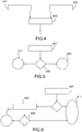
figure 4 , un synoptique présentant les étapes d'un premier mode de mise en oeuvre du procédé selon l'invention, - la
figure 5 , un synoptique présentant une première méthode utilisant le procédé selon l'invention pour discriminer les ondes ionosphériques des ondes de sol et/ou de mer, - la
figure 6 , un synoptique présentant une deuxième méthode, dérivée de la première méthode présentée enfigure 5 pour discriminer les ondes ionosphériques des ondes de sol et/ou de mer, - la
figure 7 , une illustration d'un dispositif mettant en oeuvre le procédé d'estimation de l'angle d'ellipticité τ selon l'invention.
- the
Figures 1a and 1b , a perspective and top view of a first example of a crossed-frame antenna receiving the signals processed by the method according to the invention, - the
Figures 2a and 2b a view in perspective and from above of a second example of a crossed-frame antenna receiving the signals processed by the method according to the invention, - the
figure 3a a graph illustrating a phase shift between signals received on the antenna frames when the carrier wave of said signals is vertically polarized, - the
figure 3b a graph illustrating a phase shift between signals received on the antenna frames when the carrier wave of said signals is not vertically polarized, - the
figure 4 a block diagram showing the steps of a first embodiment of the method according to the invention, - the
figure 5 , a synoptic presenting a first method using the method according to the invention for discriminating the ionospheric waves of the ground and / or sea waves, - the
figure 6 , a synoptic presenting a second method, derived from the first method presented infigure 5 to discriminate ionospheric waves from ground and / or sea waves, - the
figure 7 , an illustration of a device implementing the method of estimating the ellipticity angle τ according to the invention.
Dans un souci de clarté, les mêmes références dans des figures différentes désignent les mêmes objets.For the sake of clarity, the same references in different figures designate the same objects.
Les
L'antenne 100 comporte un premier cadre 111 orthogonal à un second cadre 112, les deux cadres 111, 112 étant, dans l'exemple, formés par des rectangles métalliques maintenus par un support 115 et inscrits dans des plans sensiblement verticaux. Le premier cadre 111 est parfois qualifié de «cadre sinus », le deuxième cadre 112 étant qualifié de « cadre cosinus ». L'antenne 100 comporte une troisième voie de réception sous la forme, dans l'exemple, d'un monopôle réalisé avec des tiges métalliques verticales 116, 117, 118, 119 placées sous les cadres 111, 112.The antenna 100 comprises a
Les
L'antenne 200 comporte deux paires 210, 220 de cadres maintenues par un support 230, les cadres de chaque paire 210, 220 étant parallèles entre-eux, les cadres 211, 212 de la première paire 210 étant orthogonaux aux cadres 221, 222 de la deuxième paire 220, tous les cadres 211, 212, 221, 222 de l'antenne étant, dans l'exemple, des rectangles métalliques inscrits dans des plans sensiblement verticaux. Dans l'exemple, les paires 210, 220 de cadres sont maintenues autour du support 230 de telle manière qu'elle forment sensiblement un carré vu de dessus. Dans l'exemple, l'antenne comporte également, sous chaque cadre 211, 212, 221, 222, une tige métallique 216, 217 226, 227, sensiblement verticale, l'ensemble de ces tiges 216, 217 226, 227 formant la voie monopôle de l'antenne. Cette antenne est, d'un point de vue théorique, équivalente à l'antenne présentée en
Selon un autre mode de mise en oeuvre du procédé selon l'invention, l'antenne à cadres croisés est remplacée par un réseau antennaire de type Adcock, ce type de réseau antennaire pouvant être modélisé de manière analogue aux antennes à cadres croisés, c'est-à-dire au moins par un cadre sinus et un cadre cosinus.According to another embodiment of the method according to the invention, the crossed-frame antenna is replaced by an antenna array of the Adcock type, this type of antenna array being able to be modeled in a similar manner to the crossed-frame antennas. that is to say at least by a sine frame and a cosine frame.
Par ailleurs, le monopôle de l'antenne peut être remplacé par un dipôle ou tout autre antenne servant de voie de référence.In addition, the monopole of the antenna can be replaced by a dipole or any other antenna serving as a reference channel.
La
Lorsque l'onde porteuse du signal est polarisé non verticalement ou qu'elle a subi l'influence de réflecteurs à proximité de l'antenne réceptrice, les signaux reçus sur les voies sinus et cosinus sont affublés d'un déphasage supplémentaire induisant une réponse elliptique des cadres, comme l'illustre la
La
Le signal reçu sur le monopôle et les deux cadres cosinus et sinus d'une antenne peut alors s'exprimer comme suit : 
La
Dans un premier temps 401, le déphasage Δϕ entre le signal de réponse sur le cadre sinus et le cadre cosinus est mesuré. Parallèlement 402, le rapport entre l'amplitude ∥ 
La valeur d'angle d'ellipticité τ ainsi calculée peut permettre, par exemple, de distinguer les ondes ionosphériques des ondes de mer et/ou de sol, comme l'illustre la
La
Une première étape 501 d'estimation de l'angle d'ellipticité τ est suivie d'une étape de test 502 comparant l'angle τ estimé avec un seuil fixé à l'avance. Si la valeur τ d'angle dépasse le seuil, alors l'onde est considérée comme une onde ionosphérique 511. Si la valeur τ d'angle ne dépasse pas le seuil fixé, l'onde est considérée comme une onde de mer et/ou de sol 512.A
Ainsi, grâce au procédé selon l'invention, il devient aisé d'éviter d'effectuer des traitements sur les ondes ionosphériques reçues par une antenne lorsque, par exemple, ces ondes sont considérées comme parasites et engendrent des mesures incohérentes.Thus, thanks to the method according to the invention, it becomes easy to avoid processing on the ionospheric waves received by an antenna when, for example, these waves are considered as parasites and generate inconsistent measurements.
La
Une première étape 501 d'estimation de l'angle d'ellipticité τ est suivie d'une première étape de test 502 comparant l'angle τ estimé avec un premier seuil. Si la valeur d'angle dépasse ce premier seuil, alors l'onde est considérée comme une onde ionosphérique 511. Sinon, une étape de pistage 603 est exécutée.A
Cette étape de pistage 603 permet de suivre la valeur d'angle d'ellipticité τ dans le temps. Une deuxième étape de test 604 permet ensuite de déterminer, en fonction de l'excursion de la valeur d'angle d'ellipticité, si l'onde est une onde ionosphérique 511. Dans l'exemple, cette deuxième étape de test 604 considère l'onde comme une onde ionosphérique 511 si l'excursion dans le temps de la valeur d'angle d'ellipticité τ dépasse un second seuil. Sinon, l'onde est considérée comme une onde de sol et/ou de mer 512.This tracking
Comme l'illustre la
Le procédé d'estimation de l'angle d'ellipticité τ selon l'invention peut également permettre d'attribuer une note de qualité à une mesure de goniométrie. En effet, lorsqu'on souhaite effectuer des mesures de goniométrie de signaux issus d'émetteurs au sol, la réception d'une onde ionosphérique peut perturber les mesures. Aussi, on peut attribuer une note de qualité décroissante en fonction de la valeur d'ellipticité τ de réponse d'antenne. Les mesures de goniométrie réalisées sur des émissions considérées comme ionosphériques peuvent alors être écartées.The method for estimating the ellipticity angle τ according to the invention can also make it possible to assign a quality score to a direction finding measurement. Indeed, when it is desired to perform goniometric measurements of signals from transmitters on the ground, the reception of an ionospheric wave can disturb the measurements. Also, a decreasing quality score can be assigned according to the ellipticity value τ of the antenna response. Direction finding measurements made on emissions considered as ionospheric can then be discarded.
Claims (6)
- A method for estimating the polarization ellipticity τ of a response signal of a crossed-loop antenna or an Adcock antenna array in response to an incident electromagnetic wave received on said antenna, characterized in that it comprises at least the following steps:∘ measuring the phase offset Δϕ between the signals acquired respectively on the cosine and sine path of the antenna (401);∘ measuring the ratio R between the amplitudes of the signals acquired respectively on the cosine and sine path of the antenna (402);∘ determining the ellipticity angle τ based on the phase offset Δϕ and on the ratio R (403).
- The method for estimating the polarization ellipticity angle τ as claimed in claim 1, characterized in that said ellipticity angle τ is determined by the following relation:


a c∥ being the amplitude of the signal received on the cosine loop, and ∥a s ∥ being the amplitude of the signal received on the sine loop. - A method for discriminating ionospheric waves from sea and/or ground waves, characterized in that it comprises at least the following steps:∘ detecting an electromagnetic wave on a crossed-loop antenna or Adcock antenna array;∘ determining (501) the polarization ellipticity angle τ of the antenna response signal to the received wave by carrying out the steps of the method as claimed in one of claims 1 and 2;∘ testing (502) the ellipticity angle value τ: if its value is greater than a chosen threshold value, said wave is then classified as an ionospheric wave (511).
- The method for discriminating ionospheric waves from sea and/or ground waves as claimed in claim 3, characterized in that, if, at the end of the test (502) of the ellipticity angle value τ, the ellipticity value is less than the chosen threshold value, said wave is then classified as a ground and/or sea wave (512).
- The method for discriminating ionospheric waves from sea and/or ground waves as claimed in claim 3, characterized in that, if, at the end of the test of the ellipticity angle value τ, this ellipticity value is less than the chosen threshold value, the detection step is then reiterated and the value of the deviation of the ellipticity angle τ is tested (604) in a recurrent manner through time: if this deviation is greater than a second chosen threshold value, the wave is then classified as an ionospheric wave.
- A device placed on the ground or in the sea, comprising a crossed-loop receive antenna (702) or an Adcock antenna array and a processing module (701) implementing the method for estimating the ellipticity angle τ as claimed in one of claims 1 and 2 in order to determine the polarization ellipticity angle τ of a response signal of the antenna to an electromagnetic wave received by the receive antenna or the antenna array.
Applications Claiming Priority (2)
| Application Number | Priority Date | Filing Date | Title |
|---|---|---|---|
| FR0806235A FR2938347B1 (en) | 2008-11-07 | 2008-11-07 | METHOD OF ESTIMATING THE POLARIZATION ELLIPTICITY OF AN ANTENNA RESPONSE SIGNAL TO AN INCIDENTAL ELECTROMAGNETIC WAVE |
| PCT/EP2009/064598 WO2010052235A1 (en) | 2008-11-07 | 2009-11-04 | Method for estimating the polarisation ellipticity of an antenna response signal to an incident electromagnetic wave |
Publications (2)
| Publication Number | Publication Date |
|---|---|
| EP2344903A1 EP2344903A1 (en) | 2011-07-20 |
| EP2344903B1 true EP2344903B1 (en) | 2016-04-20 |
Family
ID=40790898
Family Applications (1)
| Application Number | Title | Priority Date | Filing Date |
|---|---|---|---|
| EP09745062.1A Active EP2344903B1 (en) | 2008-11-07 | 2009-11-04 | Method for estimating the polarisation ellipticity of an antenna response signal to an incident electromagnetic wave |
Country Status (6)
| Country | Link |
|---|---|
| US (1) | US8773315B2 (en) |
| EP (1) | EP2344903B1 (en) |
| ES (1) | ES2581771T3 (en) |
| FR (1) | FR2938347B1 (en) |
| IL (1) | IL212772A (en) |
| WO (1) | WO2010052235A1 (en) |
Family Cites Families (4)
| Publication number | Priority date | Publication date | Assignee | Title |
|---|---|---|---|---|
| DE2740389C2 (en) * | 1977-09-08 | 1985-04-04 | Licentia Patent-Verwaltungs-Gmbh, 6000 Frankfurt | Process and arrangement for the extraction of clouded DF components |
| DE2925723A1 (en) * | 1979-06-26 | 1981-01-15 | Licentia Gmbh | Ellipse features of remote direction finder display - is computed by multiplying direction finder signals by phase shifted sense signal |
| US6249261B1 (en) * | 2000-03-23 | 2001-06-19 | Southwest Research Institute | Polymer, composite, direction-finding antenna |
| FR2939971B1 (en) * | 2008-12-16 | 2011-02-11 | Thales Sa | COMPACT EXCITATION ASSEMBLY FOR GENERATING CIRCULAR POLARIZATION IN AN ANTENNA AND METHOD FOR PRODUCING SUCH AN EXCITATION ASSEMBLY |
-
2008
- 2008-11-07 FR FR0806235A patent/FR2938347B1/en not_active Expired - Fee Related
-
2009
- 2009-11-04 WO PCT/EP2009/064598 patent/WO2010052235A1/en active Application Filing
- 2009-11-04 ES ES09745062.1T patent/ES2581771T3/en active Active
- 2009-11-04 EP EP09745062.1A patent/EP2344903B1/en active Active
- 2009-11-04 US US13/128,396 patent/US8773315B2/en not_active Expired - Fee Related
-
2011
- 2011-05-08 IL IL212772A patent/IL212772A/en active IP Right Grant
Also Published As
| Publication number | Publication date |
|---|---|
| ES2581771T3 (en) | 2016-09-07 |
| IL212772A (en) | 2014-09-30 |
| FR2938347B1 (en) | 2010-11-12 |
| US8773315B2 (en) | 2014-07-08 |
| EP2344903A1 (en) | 2011-07-20 |
| US20120127046A1 (en) | 2012-05-24 |
| IL212772A0 (en) | 2011-07-31 |
| FR2938347A1 (en) | 2010-05-14 |
| WO2010052235A1 (en) | 2010-05-14 |
Similar Documents
| Publication | Publication Date | Title |
|---|---|---|
| EP2344902B1 (en) | Method of determining the direction of arrival in terms of bearing of a high-frequency electromagnetic wave | |
| EP2318854B1 (en) | Method for protecting a radio navigation receiver user against aberrant pseudo-range measurements | |
| JP6349938B2 (en) | Measuring point information providing apparatus, fluctuation detecting apparatus, method and program | |
| EP2122388B1 (en) | Device and method for locating a mobile approaching a surface reflecting electromagnetic waves | |
| Lipa et al. | SeaSonde radial velocities: Derivation and internal consistency | |
| US9001614B1 (en) | System for self-localizing near field data processing | |
| EP2517037B1 (en) | Method for estimating the number of incident sources in a sensor array by means of estimating noise statistics | |
| EP2344901B1 (en) | Method of determining the direction of arrival of an electromagnetic wave | |
| EP2435847B1 (en) | Method and system for determining the direction of arrival of an electromagnetic wave having any polarisation | |
| WO2018115322A1 (en) | Method and system for evaluating a distance between an identifier and a vehicle, associated onboard system and identifier | |
| US20090009382A1 (en) | Method for determining signal direction using artificial doppler shifts | |
| EP3356840B1 (en) | Method for determining characteristics of an electromagnetic wave | |
| EP2344903B1 (en) | Method for estimating the polarisation ellipticity of an antenna response signal to an incident electromagnetic wave | |
| EP1227333B1 (en) | Method and device to locate a ground-based emitter from a satellite | |
| EP2965108B1 (en) | Measuring device and measuring method for direction finding and direction uncertainty determination | |
| EP3036840B1 (en) | Method for the detection of an electromagnetic signal by an antenna array, and device implementing said method | |
| EP2453261B1 (en) | Method for GNSS signal distortion detection | |
| EP3036841B1 (en) | Method for the detection of an electromagnetic signal by an antenna array with pattern diversity, and device implementing said method | |
| EP2743720B1 (en) | Method for determining the position of a transmitter without using a reference path | |
| EP3236280A1 (en) | Automatic calculation of a dimension of a mobile platform | |
| Guimaraes | Obtaining a reference for calibrating broadband multibeam seabed backscatter | |
| EP1815605B1 (en) | Method for characterising emitters by the association of parameters related to the same radio emitter | |
| Amitai et al. | Comparison of deep underwater measurements and radar observations of rainfall | |
| EP3074783B1 (en) | System and method for locating intercepted sonar transmissions | |
| FR3027406A1 (en) | METHOD FOR MEASURING SENSITIZED ECARTOMETRY WITH PARASITE SIGNALS |
Legal Events
| Date | Code | Title | Description |
|---|---|---|---|
| PUAI | Public reference made under article 153(3) epc to a published international application that has entered the european phase |
Free format text: ORIGINAL CODE: 0009012 |
|
| 17P | Request for examination filed |
Effective date: 20110509 |
|
| AK | Designated contracting states |
Kind code of ref document: A1 Designated state(s): AT BE BG CH CY CZ DE DK EE ES FI FR GB GR HR HU IE IS IT LI LT LU LV MC MK MT NL NO PL PT RO SE SI SK SM TR |
|
| AX | Request for extension of the european patent |
Extension state: AL BA RS |
|
| RIN1 | Information on inventor provided before grant (corrected) |
Inventor name: ROGIER, JEAN-LUC Inventor name: MESNAGE, JEAN-CHRISTOPHE Inventor name: LECCA, ARNAUD Inventor name: MERLET, ERIC |
|
| DAX | Request for extension of the european patent (deleted) | ||
| GRAP | Despatch of communication of intention to grant a patent |
Free format text: ORIGINAL CODE: EPIDOSNIGR1 |
|
| INTG | Intention to grant announced |
Effective date: 20160205 |
|
| GRAS | Grant fee paid |
Free format text: ORIGINAL CODE: EPIDOSNIGR3 |
|
| GRAA | (expected) grant |
Free format text: ORIGINAL CODE: 0009210 |
|
| AK | Designated contracting states |
Kind code of ref document: B1 Designated state(s): AT BE BG CH CY CZ DE DK EE ES FI FR GB GR HR HU IE IS IT LI LT LU LV MC MK MT NL NO PL PT RO SE SI SK SM TR |
|
| REG | Reference to a national code |
Ref country code: GB Ref legal event code: FG4D Free format text: NOT ENGLISH |
|
| REG | Reference to a national code |
Ref country code: CH Ref legal event code: EP |
|
| REG | Reference to a national code |
Ref country code: AT Ref legal event code: REF Ref document number: 793035 Country of ref document: AT Kind code of ref document: T Effective date: 20160515 |
|
| REG | Reference to a national code |
Ref country code: IE Ref legal event code: FG4D Free format text: LANGUAGE OF EP DOCUMENT: FRENCH |
|
| REG | Reference to a national code |
Ref country code: DE Ref legal event code: R096 Ref document number: 602009037948 Country of ref document: DE |
|
| REG | Reference to a national code |
Ref country code: CH Ref legal event code: NV Representative=s name: MARKS AND CLERK (LUXEMBOURG) LLP, CH |
|
| REG | Reference to a national code |
Ref country code: LT Ref legal event code: MG4D |
|
| REG | Reference to a national code |
Ref country code: ES Ref legal event code: FG2A Ref document number: 2581771 Country of ref document: ES Kind code of ref document: T3 Effective date: 20160907 |
|
| REG | Reference to a national code |
Ref country code: AT Ref legal event code: MK05 Ref document number: 793035 Country of ref document: AT Kind code of ref document: T Effective date: 20160420 |
|
| REG | Reference to a national code |
Ref country code: NL Ref legal event code: MP Effective date: 20160420 |
|
| REG | Reference to a national code |
Ref country code: FR Ref legal event code: PLFP Year of fee payment: 8 |
|
| PG25 | Lapsed in a contracting state [announced via postgrant information from national office to epo] |
Ref country code: NO Free format text: LAPSE BECAUSE OF FAILURE TO SUBMIT A TRANSLATION OF THE DESCRIPTION OR TO PAY THE FEE WITHIN THE PRESCRIBED TIME-LIMIT Effective date: 20160720 Ref country code: FI Free format text: LAPSE BECAUSE OF FAILURE TO SUBMIT A TRANSLATION OF THE DESCRIPTION OR TO PAY THE FEE WITHIN THE PRESCRIBED TIME-LIMIT Effective date: 20160420 Ref country code: PL Free format text: LAPSE BECAUSE OF FAILURE TO SUBMIT A TRANSLATION OF THE DESCRIPTION OR TO PAY THE FEE WITHIN THE PRESCRIBED TIME-LIMIT Effective date: 20160420 Ref country code: LT Free format text: LAPSE BECAUSE OF FAILURE TO SUBMIT A TRANSLATION OF THE DESCRIPTION OR TO PAY THE FEE WITHIN THE PRESCRIBED TIME-LIMIT Effective date: 20160420 Ref country code: NL Free format text: LAPSE BECAUSE OF FAILURE TO SUBMIT A TRANSLATION OF THE DESCRIPTION OR TO PAY THE FEE WITHIN THE PRESCRIBED TIME-LIMIT Effective date: 20160420 |
|
| PG25 | Lapsed in a contracting state [announced via postgrant information from national office to epo] |
Ref country code: GR Free format text: LAPSE BECAUSE OF FAILURE TO SUBMIT A TRANSLATION OF THE DESCRIPTION OR TO PAY THE FEE WITHIN THE PRESCRIBED TIME-LIMIT Effective date: 20160721 Ref country code: LV Free format text: LAPSE BECAUSE OF FAILURE TO SUBMIT A TRANSLATION OF THE DESCRIPTION OR TO PAY THE FEE WITHIN THE PRESCRIBED TIME-LIMIT Effective date: 20160420 Ref country code: PT Free format text: LAPSE BECAUSE OF FAILURE TO SUBMIT A TRANSLATION OF THE DESCRIPTION OR TO PAY THE FEE WITHIN THE PRESCRIBED TIME-LIMIT Effective date: 20160822 Ref country code: SE Free format text: LAPSE BECAUSE OF FAILURE TO SUBMIT A TRANSLATION OF THE DESCRIPTION OR TO PAY THE FEE WITHIN THE PRESCRIBED TIME-LIMIT Effective date: 20160420 Ref country code: AT Free format text: LAPSE BECAUSE OF FAILURE TO SUBMIT A TRANSLATION OF THE DESCRIPTION OR TO PAY THE FEE WITHIN THE PRESCRIBED TIME-LIMIT Effective date: 20160420 Ref country code: HR Free format text: LAPSE BECAUSE OF FAILURE TO SUBMIT A TRANSLATION OF THE DESCRIPTION OR TO PAY THE FEE WITHIN THE PRESCRIBED TIME-LIMIT Effective date: 20160420 |
|
| REG | Reference to a national code |
Ref country code: DE Ref legal event code: R097 Ref document number: 602009037948 Country of ref document: DE |
|
| PG25 | Lapsed in a contracting state [announced via postgrant information from national office to epo] |
Ref country code: EE Free format text: LAPSE BECAUSE OF FAILURE TO SUBMIT A TRANSLATION OF THE DESCRIPTION OR TO PAY THE FEE WITHIN THE PRESCRIBED TIME-LIMIT Effective date: 20160420 Ref country code: SK Free format text: LAPSE BECAUSE OF FAILURE TO SUBMIT A TRANSLATION OF THE DESCRIPTION OR TO PAY THE FEE WITHIN THE PRESCRIBED TIME-LIMIT Effective date: 20160420 Ref country code: DK Free format text: LAPSE BECAUSE OF FAILURE TO SUBMIT A TRANSLATION OF THE DESCRIPTION OR TO PAY THE FEE WITHIN THE PRESCRIBED TIME-LIMIT Effective date: 20160420 Ref country code: CZ Free format text: LAPSE BECAUSE OF FAILURE TO SUBMIT A TRANSLATION OF THE DESCRIPTION OR TO PAY THE FEE WITHIN THE PRESCRIBED TIME-LIMIT Effective date: 20160420 Ref country code: RO Free format text: LAPSE BECAUSE OF FAILURE TO SUBMIT A TRANSLATION OF THE DESCRIPTION OR TO PAY THE FEE WITHIN THE PRESCRIBED TIME-LIMIT Effective date: 20160420 |
|
| PLBE | No opposition filed within time limit |
Free format text: ORIGINAL CODE: 0009261 |
|
| STAA | Information on the status of an ep patent application or granted ep patent |
Free format text: STATUS: NO OPPOSITION FILED WITHIN TIME LIMIT |
|
| PG25 | Lapsed in a contracting state [announced via postgrant information from national office to epo] |
Ref country code: BE Free format text: LAPSE BECAUSE OF NON-PAYMENT OF DUE FEES Effective date: 20161130 Ref country code: SM Free format text: LAPSE BECAUSE OF FAILURE TO SUBMIT A TRANSLATION OF THE DESCRIPTION OR TO PAY THE FEE WITHIN THE PRESCRIBED TIME-LIMIT Effective date: 20160420 |
|
| 26N | No opposition filed |
Effective date: 20170123 |
|
| PG25 | Lapsed in a contracting state [announced via postgrant information from national office to epo] |
Ref country code: SI Free format text: LAPSE BECAUSE OF FAILURE TO SUBMIT A TRANSLATION OF THE DESCRIPTION OR TO PAY THE FEE WITHIN THE PRESCRIBED TIME-LIMIT Effective date: 20160420 |
|
| REG | Reference to a national code |
Ref country code: IE Ref legal event code: MM4A |
|
| PG25 | Lapsed in a contracting state [announced via postgrant information from national office to epo] |
Ref country code: LU Free format text: LAPSE BECAUSE OF NON-PAYMENT OF DUE FEES Effective date: 20161130 |
|
| REG | Reference to a national code |
Ref country code: FR Ref legal event code: PLFP Year of fee payment: 9 |
|
| PG25 | Lapsed in a contracting state [announced via postgrant information from national office to epo] |
Ref country code: IE Free format text: LAPSE BECAUSE OF NON-PAYMENT OF DUE FEES Effective date: 20161104 |
|
| REG | Reference to a national code |
Ref country code: BE Ref legal event code: MM Effective date: 20161130 |
|
| PGFP | Annual fee paid to national office [announced via postgrant information from national office to epo] |
Ref country code: GB Payment date: 20171024 Year of fee payment: 9 Ref country code: IT Payment date: 20171123 Year of fee payment: 9 |
|
| PG25 | Lapsed in a contracting state [announced via postgrant information from national office to epo] |
Ref country code: CY Free format text: LAPSE BECAUSE OF FAILURE TO SUBMIT A TRANSLATION OF THE DESCRIPTION OR TO PAY THE FEE WITHIN THE PRESCRIBED TIME-LIMIT Effective date: 20160420 Ref country code: HU Free format text: LAPSE BECAUSE OF FAILURE TO SUBMIT A TRANSLATION OF THE DESCRIPTION OR TO PAY THE FEE WITHIN THE PRESCRIBED TIME-LIMIT; INVALID AB INITIO Effective date: 20091104 |
|
| PG25 | Lapsed in a contracting state [announced via postgrant information from national office to epo] |
Ref country code: TR Free format text: LAPSE BECAUSE OF FAILURE TO SUBMIT A TRANSLATION OF THE DESCRIPTION OR TO PAY THE FEE WITHIN THE PRESCRIBED TIME-LIMIT Effective date: 20160420 Ref country code: IS Free format text: LAPSE BECAUSE OF FAILURE TO SUBMIT A TRANSLATION OF THE DESCRIPTION OR TO PAY THE FEE WITHIN THE PRESCRIBED TIME-LIMIT Effective date: 20160420 Ref country code: MK Free format text: LAPSE BECAUSE OF FAILURE TO SUBMIT A TRANSLATION OF THE DESCRIPTION OR TO PAY THE FEE WITHIN THE PRESCRIBED TIME-LIMIT Effective date: 20160420 Ref country code: MC Free format text: LAPSE BECAUSE OF FAILURE TO SUBMIT A TRANSLATION OF THE DESCRIPTION OR TO PAY THE FEE WITHIN THE PRESCRIBED TIME-LIMIT Effective date: 20160420 |
|
| PG25 | Lapsed in a contracting state [announced via postgrant information from national office to epo] |
Ref country code: BG Free format text: LAPSE BECAUSE OF FAILURE TO SUBMIT A TRANSLATION OF THE DESCRIPTION OR TO PAY THE FEE WITHIN THE PRESCRIBED TIME-LIMIT Effective date: 20160420 |
|
| PG25 | Lapsed in a contracting state [announced via postgrant information from national office to epo] |
Ref country code: MT Free format text: LAPSE BECAUSE OF FAILURE TO SUBMIT A TRANSLATION OF THE DESCRIPTION OR TO PAY THE FEE WITHIN THE PRESCRIBED TIME-LIMIT Effective date: 20160420 |
|
| REG | Reference to a national code |
Ref country code: FR Ref legal event code: PLFP Year of fee payment: 10 |
|
| PGFP | Annual fee paid to national office [announced via postgrant information from national office to epo] |
Ref country code: RS Payment date: 20181206 Year of fee payment: 6 |
|
| GBPC | Gb: european patent ceased through non-payment of renewal fee |
Effective date: 20181104 |
|
| PG25 | Lapsed in a contracting state [announced via postgrant information from national office to epo] |
Ref country code: IT Free format text: LAPSE BECAUSE OF NON-PAYMENT OF DUE FEES Effective date: 20181104 |
|
| PG25 | Lapsed in a contracting state [announced via postgrant information from national office to epo] |
Ref country code: GB Free format text: LAPSE BECAUSE OF NON-PAYMENT OF DUE FEES Effective date: 20181104 |
|
| PGFP | Annual fee paid to national office [announced via postgrant information from national office to epo] |
Ref country code: CH Payment date: 20191116 Year of fee payment: 11 |
|
| REG | Reference to a national code |
Ref country code: ES Ref legal event code: FD2A Effective date: 20210527 |
|
| REG | Reference to a national code |
Ref country code: CH Ref legal event code: PL |
|
| PG25 | Lapsed in a contracting state [announced via postgrant information from national office to epo] |
Ref country code: ES Free format text: LAPSE BECAUSE OF NON-PAYMENT OF DUE FEES Effective date: 20191105 Ref country code: LI Free format text: LAPSE BECAUSE OF NON-PAYMENT OF DUE FEES Effective date: 20201130 Ref country code: CH Free format text: LAPSE BECAUSE OF NON-PAYMENT OF DUE FEES Effective date: 20201130 |
|
| P01 | Opt-out of the competence of the unified patent court (upc) registered |
Effective date: 20230517 |
|
| PGFP | Annual fee paid to national office [announced via postgrant information from national office to epo] |
Ref country code: FR Payment date: 20231024 Year of fee payment: 15 Ref country code: DE Payment date: 20231017 Year of fee payment: 15 |