EP2344866B1 - Plasmonic electricity - Google Patents
Plasmonic electricity Download PDFInfo
- Publication number
- EP2344866B1 EP2344866B1 EP09815179.8A EP09815179A EP2344866B1 EP 2344866 B1 EP2344866 B1 EP 2344866B1 EP 09815179 A EP09815179 A EP 09815179A EP 2344866 B1 EP2344866 B1 EP 2344866B1
- Authority
- EP
- European Patent Office
- Prior art keywords
- metallic material
- current
- metallic
- assay method
- fluorophore
- Prior art date
- Legal status (The legal status is an assumption and is not a legal conclusion. Google has not performed a legal analysis and makes no representation as to the accuracy of the status listed.)
- Not-in-force
Links
- 230000005611 electricity Effects 0.000 title description 7
- 239000007769 metal material Substances 0.000 claims description 48
- 238000003556 assay Methods 0.000 claims description 38
- 239000000758 substrate Substances 0.000 claims description 26
- 230000005284 excitation Effects 0.000 claims description 22
- 239000000084 colloidal system Substances 0.000 claims description 21
- 239000013528 metallic particle Substances 0.000 claims description 21
- 238000000034 method Methods 0.000 claims description 19
- 229910052709 silver Inorganic materials 0.000 claims description 19
- 239000004332 silver Substances 0.000 claims description 19
- 239000010931 gold Substances 0.000 claims description 17
- BQCADISMDOOEFD-UHFFFAOYSA-N Silver Chemical compound [Ag] BQCADISMDOOEFD-UHFFFAOYSA-N 0.000 claims description 16
- PCHJSUWPFVWCPO-UHFFFAOYSA-N gold Chemical compound [Au] PCHJSUWPFVWCPO-UHFFFAOYSA-N 0.000 claims description 15
- 229910052737 gold Inorganic materials 0.000 claims description 15
- 239000002086 nanomaterial Substances 0.000 claims description 14
- 230000001939 inductive effect Effects 0.000 claims description 10
- 238000004020 luminiscence type Methods 0.000 claims description 8
- 230000003287 optical effect Effects 0.000 claims description 7
- BASFCYQUMIYNBI-UHFFFAOYSA-N platinum Chemical compound [Pt] BASFCYQUMIYNBI-UHFFFAOYSA-N 0.000 claims description 7
- 239000002798 polar solvent Substances 0.000 claims description 7
- 239000012491 analyte Substances 0.000 claims description 6
- 239000011521 glass Substances 0.000 claims description 6
- VYPSYNLAJGMNEJ-UHFFFAOYSA-N silicon dioxide Inorganic materials O=[Si]=O VYPSYNLAJGMNEJ-UHFFFAOYSA-N 0.000 claims description 6
- 239000000463 material Substances 0.000 claims description 5
- 239000010453 quartz Substances 0.000 claims description 5
- RYGMFSIKBFXOCR-UHFFFAOYSA-N Copper Chemical compound [Cu] RYGMFSIKBFXOCR-UHFFFAOYSA-N 0.000 claims description 4
- 229910052802 copper Inorganic materials 0.000 claims description 4
- 239000010949 copper Substances 0.000 claims description 4
- 238000009396 hybridization Methods 0.000 claims description 4
- 229910052697 platinum Inorganic materials 0.000 claims description 4
- 230000005855 radiation Effects 0.000 claims description 4
- 238000002965 ELISA Methods 0.000 claims description 2
- HCHKCACWOHOZIP-UHFFFAOYSA-N Zinc Chemical compound [Zn] HCHKCACWOHOZIP-UHFFFAOYSA-N 0.000 claims description 2
- 229910052782 aluminium Inorganic materials 0.000 claims description 2
- XAGFODPZIPBFFR-UHFFFAOYSA-N aluminium Chemical compound [Al] XAGFODPZIPBFFR-UHFFFAOYSA-N 0.000 claims description 2
- 230000010287 polarization Effects 0.000 claims description 2
- 238000002165 resonance energy transfer Methods 0.000 claims description 2
- 229910052725 zinc Inorganic materials 0.000 claims description 2
- 239000011701 zinc Substances 0.000 claims description 2
- 229910052751 metal Inorganic materials 0.000 description 33
- 239000002184 metal Substances 0.000 description 32
- 239000000427 antigen Substances 0.000 description 16
- 102000036639 antigens Human genes 0.000 description 16
- 108091007433 antigens Proteins 0.000 description 16
- 101150099086 sif gene Proteins 0.000 description 15
- 239000000243 solution Substances 0.000 description 15
- 239000010408 film Substances 0.000 description 14
- 239000000523 sample Substances 0.000 description 14
- 108091028043 Nucleic acid sequence Proteins 0.000 description 12
- 238000006243 chemical reaction Methods 0.000 description 11
- 238000001514 detection method Methods 0.000 description 11
- 230000000694 effects Effects 0.000 description 11
- 239000002245 particle Substances 0.000 description 11
- 241000894007 species Species 0.000 description 11
- 102000003992 Peroxidases Human genes 0.000 description 9
- 239000003795 chemical substances by application Substances 0.000 description 9
- 238000005516 engineering process Methods 0.000 description 9
- 108040007629 peroxidase activity proteins Proteins 0.000 description 9
- XLYOFNOQVPJJNP-UHFFFAOYSA-N water Substances O XLYOFNOQVPJJNP-UHFFFAOYSA-N 0.000 description 9
- 238000003018 immunoassay Methods 0.000 description 8
- 239000011159 matrix material Substances 0.000 description 7
- -1 such as Substances 0.000 description 7
- 230000003993 interaction Effects 0.000 description 6
- 150000002739 metals Chemical class 0.000 description 6
- 244000052769 pathogen Species 0.000 description 6
- 230000001717 pathogenic effect Effects 0.000 description 6
- JWDFQMWEFLOOED-UHFFFAOYSA-N (2,5-dioxopyrrolidin-1-yl) 3-(pyridin-2-yldisulfanyl)propanoate Chemical compound O=C1CCC(=O)N1OC(=O)CCSSC1=CC=CC=N1 JWDFQMWEFLOOED-UHFFFAOYSA-N 0.000 description 5
- 238000004166 bioassay Methods 0.000 description 5
- 239000002923 metal particle Substances 0.000 description 5
- 108020004414 DNA Proteins 0.000 description 4
- PXHVJJICTQNCMI-UHFFFAOYSA-N Nickel Chemical compound [Ni] PXHVJJICTQNCMI-UHFFFAOYSA-N 0.000 description 4
- 238000000862 absorption spectrum Methods 0.000 description 4
- 235000014113 dietary fatty acids Nutrition 0.000 description 4
- 239000000975 dye Substances 0.000 description 4
- 239000000194 fatty acid Substances 0.000 description 4
- 229930195729 fatty acid Natural products 0.000 description 4
- 230000001965 increasing effect Effects 0.000 description 4
- 239000002105 nanoparticle Substances 0.000 description 4
- 230000035945 sensitivity Effects 0.000 description 4
- 239000000126 substance Substances 0.000 description 4
- 239000004753 textile Substances 0.000 description 4
- 150000003573 thiols Chemical class 0.000 description 4
- QTBSBXVTEAMEQO-UHFFFAOYSA-N Acetic acid Chemical compound CC(O)=O QTBSBXVTEAMEQO-UHFFFAOYSA-N 0.000 description 3
- CSCPPACGZOOCGX-UHFFFAOYSA-N Acetone Chemical compound CC(C)=O CSCPPACGZOOCGX-UHFFFAOYSA-N 0.000 description 3
- OKKJLVBELUTLKV-UHFFFAOYSA-N Methanol Chemical compound OC OKKJLVBELUTLKV-UHFFFAOYSA-N 0.000 description 3
- KDLHZDBZIXYQEI-UHFFFAOYSA-N Palladium Chemical compound [Pd] KDLHZDBZIXYQEI-UHFFFAOYSA-N 0.000 description 3
- HEMHJVSKTPXQMS-UHFFFAOYSA-M Sodium hydroxide Chemical compound [OH-].[Na+] HEMHJVSKTPXQMS-UHFFFAOYSA-M 0.000 description 3
- 238000010521 absorption reaction Methods 0.000 description 3
- 229910045601 alloy Inorganic materials 0.000 description 3
- 239000000956 alloy Substances 0.000 description 3
- 125000003118 aryl group Chemical group 0.000 description 3
- 230000003247 decreasing effect Effects 0.000 description 3
- 150000004665 fatty acids Chemical class 0.000 description 3
- 150000002632 lipids Chemical class 0.000 description 3
- 108020004707 nucleic acids Proteins 0.000 description 3
- 150000007523 nucleic acids Chemical class 0.000 description 3
- 102000039446 nucleic acids Human genes 0.000 description 3
- 108090000765 processed proteins & peptides Proteins 0.000 description 3
- 102000004169 proteins and genes Human genes 0.000 description 3
- 108090000623 proteins and genes Proteins 0.000 description 3
- 238000006722 reduction reaction Methods 0.000 description 3
- 239000010936 titanium Substances 0.000 description 3
- 125000004178 (C1-C4) alkyl group Chemical group 0.000 description 2
- 108091032973 (ribonucleotides)n+m Proteins 0.000 description 2
- HMWAJFNEGAJETK-UHFFFAOYSA-N 1-[6-(dimethylamino)naphthalen-2-yl]prop-2-en-1-one Chemical compound C1=C(C(=O)C=C)C=CC2=CC(N(C)C)=CC=C21 HMWAJFNEGAJETK-UHFFFAOYSA-N 0.000 description 2
- FWEOQOXTVHGIFQ-UHFFFAOYSA-N 8-anilinonaphthalene-1-sulfonic acid Chemical compound C=12C(S(=O)(=O)O)=CC=CC2=CC=CC=1NC1=CC=CC=C1 FWEOQOXTVHGIFQ-UHFFFAOYSA-N 0.000 description 2
- DLFVBJFMPXGRIB-UHFFFAOYSA-N Acetamide Chemical compound CC(N)=O DLFVBJFMPXGRIB-UHFFFAOYSA-N 0.000 description 2
- BPYKTIZUTYGOLE-IFADSCNNSA-N Bilirubin Chemical compound N1C(=O)C(C)=C(C=C)\C1=C\C1=C(C)C(CCC(O)=O)=C(CC2=C(C(C)=C(\C=C/3C(=C(C=C)C(=O)N\3)C)N2)CCC(O)=O)N1 BPYKTIZUTYGOLE-IFADSCNNSA-N 0.000 description 2
- OYPRJOBELJOOCE-UHFFFAOYSA-N Calcium Chemical compound [Ca] OYPRJOBELJOOCE-UHFFFAOYSA-N 0.000 description 2
- XFXPMWWXUTWYJX-UHFFFAOYSA-N Cyanide Chemical group N#[C-] XFXPMWWXUTWYJX-UHFFFAOYSA-N 0.000 description 2
- XPDXVDYUQZHFPV-UHFFFAOYSA-N Dansyl Chloride Chemical compound C1=CC=C2C(N(C)C)=CC=CC2=C1S(Cl)(=O)=O XPDXVDYUQZHFPV-UHFFFAOYSA-N 0.000 description 2
- WQZGKKKJIJFFOK-GASJEMHNSA-N Glucose Natural products OC[C@H]1OC(O)[C@H](O)[C@@H](O)[C@@H]1O WQZGKKKJIJFFOK-GASJEMHNSA-N 0.000 description 2
- 108010043121 Green Fluorescent Proteins Proteins 0.000 description 2
- 102000004144 Green Fluorescent Proteins Human genes 0.000 description 2
- MHAJPDPJQMAIIY-UHFFFAOYSA-N Hydrogen peroxide Chemical compound OO MHAJPDPJQMAIIY-UHFFFAOYSA-N 0.000 description 2
- XEEYBQQBJWHFJM-UHFFFAOYSA-N Iron Chemical compound [Fe] XEEYBQQBJWHFJM-UHFFFAOYSA-N 0.000 description 2
- AMIMRNSIRUDHCM-UHFFFAOYSA-N Isopropylaldehyde Chemical compound CC(C)C=O AMIMRNSIRUDHCM-UHFFFAOYSA-N 0.000 description 2
- 102000036675 Myoglobin Human genes 0.000 description 2
- 108010062374 Myoglobin Proteins 0.000 description 2
- 241000283973 Oryctolagus cuniculus Species 0.000 description 2
- FOIXSVOLVBLSDH-UHFFFAOYSA-N Silver ion Chemical compound [Ag+] FOIXSVOLVBLSDH-UHFFFAOYSA-N 0.000 description 2
- 150000001413 amino acids Chemical class 0.000 description 2
- 238000013459 approach Methods 0.000 description 2
- 230000008901 benefit Effects 0.000 description 2
- DZBUGLKDJFMEHC-UHFFFAOYSA-N benzoquinolinylidene Natural products C1=CC=CC2=CC3=CC=CC=C3N=C21 DZBUGLKDJFMEHC-UHFFFAOYSA-N 0.000 description 2
- 230000008033 biological extinction Effects 0.000 description 2
- 230000008827 biological function Effects 0.000 description 2
- 229910052791 calcium Inorganic materials 0.000 description 2
- 239000011575 calcium Substances 0.000 description 2
- 239000003638 chemical reducing agent Substances 0.000 description 2
- 230000000295 complement effect Effects 0.000 description 2
- VPUGDVKSAQVFFS-UHFFFAOYSA-N coronene Chemical compound C1=C(C2=C34)C=CC3=CC=C(C=C3)C4=C4C3=CC=C(C=C3)C4=C2C3=C1 VPUGDVKSAQVFFS-UHFFFAOYSA-N 0.000 description 2
- 230000008878 coupling Effects 0.000 description 2
- 238000010168 coupling process Methods 0.000 description 2
- 238000005859 coupling reaction Methods 0.000 description 2
- 230000001419 dependent effect Effects 0.000 description 2
- 230000005281 excited state Effects 0.000 description 2
- GNBHRKFJIUUOQI-UHFFFAOYSA-N fluorescein Chemical compound O1C(=O)C2=CC=CC=C2C21C1=CC=C(O)C=C1OC1=CC(O)=CC=C21 GNBHRKFJIUUOQI-UHFFFAOYSA-N 0.000 description 2
- 239000007850 fluorescent dye Substances 0.000 description 2
- 239000008103 glucose Substances 0.000 description 2
- KWIUHFFTVRNATP-UHFFFAOYSA-N glycine betaine Chemical compound C[N+](C)(C)CC([O-])=O KWIUHFFTVRNATP-UHFFFAOYSA-N 0.000 description 2
- 229910052739 hydrogen Inorganic materials 0.000 description 2
- FDGQSTZJBFJUBT-UHFFFAOYSA-N hypoxanthine Chemical compound O=C1NC=NC2=C1NC=N2 FDGQSTZJBFJUBT-UHFFFAOYSA-N 0.000 description 2
- 238000005286 illumination Methods 0.000 description 2
- 230000006698 induction Effects 0.000 description 2
- 229910052741 iridium Inorganic materials 0.000 description 2
- 230000004298 light response Effects 0.000 description 2
- HWYHZTIRURJOHG-UHFFFAOYSA-N luminol Chemical compound O=C1NNC(=O)C2=C1C(N)=CC=C2 HWYHZTIRURJOHG-UHFFFAOYSA-N 0.000 description 2
- 238000005259 measurement Methods 0.000 description 2
- 239000000203 mixture Substances 0.000 description 2
- 238000012544 monitoring process Methods 0.000 description 2
- 229910052759 nickel Inorganic materials 0.000 description 2
- 229930027945 nicotinamide-adenine dinucleotide Natural products 0.000 description 2
- BOPGDPNILDQYTO-NNYOXOHSSA-N nicotinamide-adenine dinucleotide Chemical compound C1=CCC(C(=O)N)=CN1[C@H]1[C@H](O)[C@H](O)[C@@H](COP(O)(=O)OP(O)(=O)OC[C@@H]2[C@H]([C@@H](O)[C@@H](O2)N2C3=NC=NC(N)=C3N=C2)O)O1 BOPGDPNILDQYTO-NNYOXOHSSA-N 0.000 description 2
- 229910000510 noble metal Inorganic materials 0.000 description 2
- 229910052763 palladium Inorganic materials 0.000 description 2
- IJTNSXPMYKJZPR-UHFFFAOYSA-N parinaric acid Chemical compound CCC=CC=CC=CC=CCCCCCCCC(O)=O IJTNSXPMYKJZPR-UHFFFAOYSA-N 0.000 description 2
- 239000002244 precipitate Substances 0.000 description 2
- 238000002360 preparation method Methods 0.000 description 2
- 102000004196 processed proteins & peptides Human genes 0.000 description 2
- 150000003212 purines Chemical class 0.000 description 2
- 230000009467 reduction Effects 0.000 description 2
- SQGYOTSLMSWVJD-UHFFFAOYSA-N silver(1+) nitrate Chemical compound [Ag+].[O-]N(=O)=O SQGYOTSLMSWVJD-UHFFFAOYSA-N 0.000 description 2
- 239000007787 solid Substances 0.000 description 2
- 235000000346 sugar Nutrition 0.000 description 2
- 229910052715 tantalum Inorganic materials 0.000 description 2
- 238000012360 testing method Methods 0.000 description 2
- 239000010409 thin film Substances 0.000 description 2
- 229910052719 titanium Inorganic materials 0.000 description 2
- 239000011782 vitamin Substances 0.000 description 2
- 229940088594 vitamin Drugs 0.000 description 2
- 229930003231 vitamin Natural products 0.000 description 2
- 235000013343 vitamin Nutrition 0.000 description 2
- XJZXHBYIBXUEMY-UHFFFAOYSA-N (2z)-3-propyl-2-[(2z,4z)-5-(3-propyl-1,3-benzothiazol-3-ium-2-yl)penta-2,4-dienylidene]-1,3-benzothiazole Chemical compound S1C2=CC=CC=C2[N+](CCC)=C1C=CC=CC=C1N(CCC)C2=CC=CC=C2S1 XJZXHBYIBXUEMY-UHFFFAOYSA-N 0.000 description 1
- 125000000229 (C1-C4)alkoxy group Chemical group 0.000 description 1
- JABNPSKWVNCGMX-UHFFFAOYSA-N 2-(4-ethoxyphenyl)-6-[6-(4-methylpiperazin-1-yl)-1h-benzimidazol-2-yl]-1h-benzimidazole;trihydrochloride Chemical compound Cl.Cl.Cl.C1=CC(OCC)=CC=C1C1=NC2=CC=C(C=3NC4=CC(=CC=C4N=3)N3CCN(C)CC3)C=C2N1 JABNPSKWVNCGMX-UHFFFAOYSA-N 0.000 description 1
- LMSDCGXQALIMLM-UHFFFAOYSA-N 2-[2-[bis(carboxymethyl)amino]ethyl-(carboxymethyl)amino]acetic acid;iron Chemical compound [Fe].OC(=O)CN(CC(O)=O)CCN(CC(O)=O)CC(O)=O LMSDCGXQALIMLM-UHFFFAOYSA-N 0.000 description 1
- JTXMVXSTHSMVQF-UHFFFAOYSA-N 2-acetyloxyethyl acetate Chemical compound CC(=O)OCCOC(C)=O JTXMVXSTHSMVQF-UHFFFAOYSA-N 0.000 description 1
- GOLORTLGFDVFDW-UHFFFAOYSA-N 3-(1h-benzimidazol-2-yl)-7-(diethylamino)chromen-2-one Chemical compound C1=CC=C2NC(C3=CC4=CC=C(C=C4OC3=O)N(CC)CC)=NC2=C1 GOLORTLGFDVFDW-UHFFFAOYSA-N 0.000 description 1
- FWBHETKCLVMNFS-UHFFFAOYSA-N 4',6-Diamino-2-phenylindol Chemical compound C1=CC(C(=N)N)=CC=C1C1=CC2=CC=C(C(N)=N)C=C2N1 FWBHETKCLVMNFS-UHFFFAOYSA-N 0.000 description 1
- IZWQPBUIXGHLMT-UHFFFAOYSA-N 4-[2-(1-methylpyridin-1-ium-4-yl)ethenyl]-n,n-dipentylaniline Chemical compound C1=CC(N(CCCCC)CCCCC)=CC=C1C=CC1=CC=[N+](C)C=C1 IZWQPBUIXGHLMT-UHFFFAOYSA-N 0.000 description 1
- GBPBPEPUZCTZLS-UHFFFAOYSA-M 4-[2-(1-methylpyridin-1-ium-4-yl)ethenyl]-n,n-dipentylaniline;iodide Chemical compound [I-].C1=CC(N(CCCCC)CCCCC)=CC=C1\C=C\C1=CC=[N+](C)C=C1 GBPBPEPUZCTZLS-UHFFFAOYSA-M 0.000 description 1
- HUDPLKWXRLNSPC-UHFFFAOYSA-N 4-aminophthalhydrazide Chemical compound O=C1NNC(=O)C=2C1=CC(N)=CC=2 HUDPLKWXRLNSPC-UHFFFAOYSA-N 0.000 description 1
- ZKARERKEBVSZCX-VMDDUYISSA-M 4-methylbenzenesulfonate;trimethyl-[4-[(1e,3e,5e)-6-phenylhexa-1,3,5-trienyl]phenyl]azanium Chemical compound CC1=CC=C(S([O-])(=O)=O)C=C1.C1=CC([N+](C)(C)C)=CC=C1\C=C\C=C\C=C\C1=CC=CC=C1 ZKARERKEBVSZCX-VMDDUYISSA-M 0.000 description 1
- YERWMQJEYUIJBO-UHFFFAOYSA-N 5-chlorosulfonyl-2-[3-(diethylamino)-6-diethylazaniumylidenexanthen-9-yl]benzenesulfonate Chemical compound C=12C=CC(=[N+](CC)CC)C=C2OC2=CC(N(CC)CC)=CC=C2C=1C1=CC=C(S(Cl)(=O)=O)C=C1S([O-])(=O)=O YERWMQJEYUIJBO-UHFFFAOYSA-N 0.000 description 1
- VTRBOZNMGVDGHY-UHFFFAOYSA-N 6-(4-methylanilino)naphthalene-2-sulfonic acid Chemical compound C1=CC(C)=CC=C1NC1=CC=C(C=C(C=C2)S(O)(=O)=O)C2=C1 VTRBOZNMGVDGHY-UHFFFAOYSA-N 0.000 description 1
- 239000012099 Alexa Fluor family Substances 0.000 description 1
- VHUUQVKOLVNVRT-UHFFFAOYSA-N Ammonium hydroxide Chemical compound [NH4+].[OH-] VHUUQVKOLVNVRT-UHFFFAOYSA-N 0.000 description 1
- FTEDXVNDVHYDQW-UHFFFAOYSA-N BAPTA Chemical compound OC(=O)CN(CC(O)=O)C1=CC=CC=C1OCCOC1=CC=CC=C1N(CC(O)=O)CC(O)=O FTEDXVNDVHYDQW-UHFFFAOYSA-N 0.000 description 1
- 108090000363 Bacterial Luciferases Proteins 0.000 description 1
- CPELXLSAUQHCOX-UHFFFAOYSA-M Bromide Chemical group [Br-] CPELXLSAUQHCOX-UHFFFAOYSA-M 0.000 description 1
- OKTJSMMVPCPJKN-UHFFFAOYSA-N Carbon Chemical group [C] OKTJSMMVPCPJKN-UHFFFAOYSA-N 0.000 description 1
- VEXZGXHMUGYJMC-UHFFFAOYSA-M Chloride anion Chemical compound [Cl-] VEXZGXHMUGYJMC-UHFFFAOYSA-M 0.000 description 1
- VYZAMTAEIAYCRO-UHFFFAOYSA-N Chromium Chemical compound [Cr] VYZAMTAEIAYCRO-UHFFFAOYSA-N 0.000 description 1
- KRKNYBCHXYNGOX-UHFFFAOYSA-K Citrate Chemical compound [O-]C(=O)CC(O)(CC([O-])=O)C([O-])=O KRKNYBCHXYNGOX-UHFFFAOYSA-K 0.000 description 1
- 0 FC(c1ccccc1C*1=C(C=CC=C2)C2=CC2C1=CC=CC2)(F)F Chemical compound FC(c1ccccc1C*1=C(C=CC=C2)C2=CC2C1=CC=CC2)(F)F 0.000 description 1
- 108090000331 Firefly luciferases Proteins 0.000 description 1
- VWWQXMAJTJZDQX-UHFFFAOYSA-N Flavine adenine dinucleotide Natural products C1=NC2=C(N)N=CN=C2N1C(C(O)C1O)OC1COP(O)(=O)OP(O)(=O)OCC(O)C(O)C(O)CN1C2=NC(=O)NC(=O)C2=NC2=C1C=C(C)C(C)=C2 VWWQXMAJTJZDQX-UHFFFAOYSA-N 0.000 description 1
- 229930191892 Formycin Natural products 0.000 description 1
- KBHMEHLJSZMEMI-UHFFFAOYSA-N Formycin A Natural products N1N=C2C(N)=NC=NC2=C1C1OC(CO)C(O)C1O KBHMEHLJSZMEMI-UHFFFAOYSA-N 0.000 description 1
- SXRSQZLOMIGNAQ-UHFFFAOYSA-N Glutaraldehyde Chemical compound O=CCCCC=O SXRSQZLOMIGNAQ-UHFFFAOYSA-N 0.000 description 1
- 108010001336 Horseradish Peroxidase Proteins 0.000 description 1
- 102000008100 Human Serum Albumin Human genes 0.000 description 1
- 108091006905 Human Serum Albumin Proteins 0.000 description 1
- VEXZGXHMUGYJMC-UHFFFAOYSA-N Hydrochloric acid Chemical compound Cl VEXZGXHMUGYJMC-UHFFFAOYSA-N 0.000 description 1
- UGQMRVRMYYASKQ-UHFFFAOYSA-N Hypoxanthine nucleoside Natural products OC1C(O)C(CO)OC1N1C(NC=NC2=O)=C2N=C1 UGQMRVRMYYASKQ-UHFFFAOYSA-N 0.000 description 1
- QIVBCDIJIAJPQS-VIFPVBQESA-N L-tryptophane Chemical compound C1=CC=C2C(C[C@H](N)C(O)=O)=CNC2=C1 QIVBCDIJIAJPQS-VIFPVBQESA-N 0.000 description 1
- OUYCCCASQSFEME-QMMMGPOBSA-N L-tyrosine Chemical compound OC(=O)[C@@H](N)CC1=CC=C(O)C=C1 OUYCCCASQSFEME-QMMMGPOBSA-N 0.000 description 1
- ZOKXTWBITQBERF-UHFFFAOYSA-N Molybdenum Chemical compound [Mo] ZOKXTWBITQBERF-UHFFFAOYSA-N 0.000 description 1
- 108091034117 Oligonucleotide Proteins 0.000 description 1
- 206010033645 Pancreatitis Diseases 0.000 description 1
- KJTLSVCANCCWHF-UHFFFAOYSA-N Ruthenium Chemical compound [Ru] KJTLSVCANCCWHF-UHFFFAOYSA-N 0.000 description 1
- 206010040070 Septic Shock Diseases 0.000 description 1
- ATJFFYVFTNAWJD-UHFFFAOYSA-N Tin Chemical compound [Sn] ATJFFYVFTNAWJD-UHFFFAOYSA-N 0.000 description 1
- RTAQQCXQSZGOHL-UHFFFAOYSA-N Titanium Chemical compound [Ti] RTAQQCXQSZGOHL-UHFFFAOYSA-N 0.000 description 1
- MZZINWWGSYUHGU-UHFFFAOYSA-J ToTo-1 Chemical compound [I-].[I-].[I-].[I-].C12=CC=CC=C2C(C=C2N(C3=CC=CC=C3S2)C)=CC=[N+]1CCC[N+](C)(C)CCC[N+](C)(C)CCC[N+](C1=CC=CC=C11)=CC=C1C=C1N(C)C2=CC=CC=C2S1 MZZINWWGSYUHGU-UHFFFAOYSA-J 0.000 description 1
- 231100000650 Toxic shock syndrome Toxicity 0.000 description 1
- 206010044248 Toxic shock syndrome Diseases 0.000 description 1
- QIVBCDIJIAJPQS-UHFFFAOYSA-N Tryptophan Natural products C1=CC=C2C(CC(N)C(O)=O)=CNC2=C1 QIVBCDIJIAJPQS-UHFFFAOYSA-N 0.000 description 1
- 108010093894 Xanthine oxidase Proteins 0.000 description 1
- 102100033220 Xanthine oxidase Human genes 0.000 description 1
- JLCPHMBAVCMARE-UHFFFAOYSA-N [3-[[3-[[3-[[3-[[3-[[3-[[3-[[3-[[3-[[3-[[3-[[5-(2-amino-6-oxo-1H-purin-9-yl)-3-[[3-[[3-[[3-[[3-[[3-[[5-(2-amino-6-oxo-1H-purin-9-yl)-3-[[5-(2-amino-6-oxo-1H-purin-9-yl)-3-hydroxyoxolan-2-yl]methoxy-hydroxyphosphoryl]oxyoxolan-2-yl]methoxy-hydroxyphosphoryl]oxy-5-(5-methyl-2,4-dioxopyrimidin-1-yl)oxolan-2-yl]methoxy-hydroxyphosphoryl]oxy-5-(6-aminopurin-9-yl)oxolan-2-yl]methoxy-hydroxyphosphoryl]oxy-5-(6-aminopurin-9-yl)oxolan-2-yl]methoxy-hydroxyphosphoryl]oxy-5-(6-aminopurin-9-yl)oxolan-2-yl]methoxy-hydroxyphosphoryl]oxy-5-(6-aminopurin-9-yl)oxolan-2-yl]methoxy-hydroxyphosphoryl]oxyoxolan-2-yl]methoxy-hydroxyphosphoryl]oxy-5-(5-methyl-2,4-dioxopyrimidin-1-yl)oxolan-2-yl]methoxy-hydroxyphosphoryl]oxy-5-(4-amino-2-oxopyrimidin-1-yl)oxolan-2-yl]methoxy-hydroxyphosphoryl]oxy-5-(5-methyl-2,4-dioxopyrimidin-1-yl)oxolan-2-yl]methoxy-hydroxyphosphoryl]oxy-5-(5-methyl-2,4-dioxopyrimidin-1-yl)oxolan-2-yl]methoxy-hydroxyphosphoryl]oxy-5-(6-aminopurin-9-yl)oxolan-2-yl]methoxy-hydroxyphosphoryl]oxy-5-(6-aminopurin-9-yl)oxolan-2-yl]methoxy-hydroxyphosphoryl]oxy-5-(4-amino-2-oxopyrimidin-1-yl)oxolan-2-yl]methoxy-hydroxyphosphoryl]oxy-5-(4-amino-2-oxopyrimidin-1-yl)oxolan-2-yl]methoxy-hydroxyphosphoryl]oxy-5-(4-amino-2-oxopyrimidin-1-yl)oxolan-2-yl]methoxy-hydroxyphosphoryl]oxy-5-(6-aminopurin-9-yl)oxolan-2-yl]methoxy-hydroxyphosphoryl]oxy-5-(4-amino-2-oxopyrimidin-1-yl)oxolan-2-yl]methyl [5-(6-aminopurin-9-yl)-2-(hydroxymethyl)oxolan-3-yl] hydrogen phosphate Polymers Cc1cn(C2CC(OP(O)(=O)OCC3OC(CC3OP(O)(=O)OCC3OC(CC3O)n3cnc4c3nc(N)[nH]c4=O)n3cnc4c3nc(N)[nH]c4=O)C(COP(O)(=O)OC3CC(OC3COP(O)(=O)OC3CC(OC3COP(O)(=O)OC3CC(OC3COP(O)(=O)OC3CC(OC3COP(O)(=O)OC3CC(OC3COP(O)(=O)OC3CC(OC3COP(O)(=O)OC3CC(OC3COP(O)(=O)OC3CC(OC3COP(O)(=O)OC3CC(OC3COP(O)(=O)OC3CC(OC3COP(O)(=O)OC3CC(OC3COP(O)(=O)OC3CC(OC3COP(O)(=O)OC3CC(OC3COP(O)(=O)OC3CC(OC3COP(O)(=O)OC3CC(OC3COP(O)(=O)OC3CC(OC3COP(O)(=O)OC3CC(OC3CO)n3cnc4c(N)ncnc34)n3ccc(N)nc3=O)n3cnc4c(N)ncnc34)n3ccc(N)nc3=O)n3ccc(N)nc3=O)n3ccc(N)nc3=O)n3cnc4c(N)ncnc34)n3cnc4c(N)ncnc34)n3cc(C)c(=O)[nH]c3=O)n3cc(C)c(=O)[nH]c3=O)n3ccc(N)nc3=O)n3cc(C)c(=O)[nH]c3=O)n3cnc4c3nc(N)[nH]c4=O)n3cnc4c(N)ncnc34)n3cnc4c(N)ncnc34)n3cnc4c(N)ncnc34)n3cnc4c(N)ncnc34)O2)c(=O)[nH]c1=O JLCPHMBAVCMARE-UHFFFAOYSA-N 0.000 description 1
- JQRLYSGCPHSLJI-UHFFFAOYSA-N [Fe].N1C(C=C2N=C(C=C3NC(=C4)C=C3)C=C2)=CC=C1C=C1C=CC4=N1 Chemical class [Fe].N1C(C=C2N=C(C=C3NC(=C4)C=C3)C=C2)=CC=C1C=C1C=CC4=N1 JQRLYSGCPHSLJI-UHFFFAOYSA-N 0.000 description 1
- DPKHZNPWBDQZCN-UHFFFAOYSA-N acridine orange free base Chemical compound C1=CC(N(C)C)=CC2=NC3=CC(N(C)C)=CC=C3C=C21 DPKHZNPWBDQZCN-UHFFFAOYSA-N 0.000 description 1
- 239000000654 additive Substances 0.000 description 1
- 230000002776 aggregation Effects 0.000 description 1
- 238000004220 aggregation Methods 0.000 description 1
- IJTNSXPMYKJZPR-WVRBZULHSA-N alpha-parinaric acid Natural products CCC=C/C=C/C=C/C=CCCCCCCCC(=O)O IJTNSXPMYKJZPR-WVRBZULHSA-N 0.000 description 1
- 230000004075 alteration Effects 0.000 description 1
- 150000001412 amines Chemical class 0.000 description 1
- 239000000908 ammonium hydroxide Substances 0.000 description 1
- 239000000010 aprotic solvent Substances 0.000 description 1
- 239000007864 aqueous solution Substances 0.000 description 1
- QVGXLLKOCUKJST-UHFFFAOYSA-N atomic oxygen Chemical compound [O] QVGXLLKOCUKJST-UHFFFAOYSA-N 0.000 description 1
- 230000002238 attenuated effect Effects 0.000 description 1
- 229960003237 betaine Drugs 0.000 description 1
- ZADPBFCGQRWHPN-UHFFFAOYSA-N boronic acid Chemical compound OBO ZADPBFCGQRWHPN-UHFFFAOYSA-N 0.000 description 1
- 239000005388 borosilicate glass Substances 0.000 description 1
- 150000001720 carbohydrates Chemical class 0.000 description 1
- 235000014633 carbohydrates Nutrition 0.000 description 1
- 125000003178 carboxy group Chemical group [H]OC(*)=O 0.000 description 1
- 239000000919 ceramic Substances 0.000 description 1
- 125000003636 chemical group Chemical group 0.000 description 1
- 239000013626 chemical specie Substances 0.000 description 1
- 150000001805 chlorine compounds Chemical group 0.000 description 1
- 229910052804 chromium Inorganic materials 0.000 description 1
- 239000011651 chromium Substances 0.000 description 1
- 239000011248 coating agent Substances 0.000 description 1
- 238000000576 coating method Methods 0.000 description 1
- 229910017052 cobalt Inorganic materials 0.000 description 1
- 239000010941 cobalt Substances 0.000 description 1
- GUTLYIVDDKVIGB-UHFFFAOYSA-N cobalt atom Chemical compound [Co] GUTLYIVDDKVIGB-UHFFFAOYSA-N 0.000 description 1
- 238000004891 communication Methods 0.000 description 1
- 239000011246 composite particle Substances 0.000 description 1
- 150000001875 compounds Chemical class 0.000 description 1
- 239000002322 conducting polymer Substances 0.000 description 1
- 229920001940 conductive polymer Polymers 0.000 description 1
- 239000004020 conductor Substances 0.000 description 1
- 238000001816 cooling Methods 0.000 description 1
- 238000012937 correction Methods 0.000 description 1
- VHJLVAABSRFDPM-QWWZWVQMSA-N dithiothreitol Chemical compound SC[C@@H](O)[C@H](O)CS VHJLVAABSRFDPM-QWWZWVQMSA-N 0.000 description 1
- 239000003814 drug Substances 0.000 description 1
- 238000001378 electrochemiluminescence detection Methods 0.000 description 1
- 239000003792 electrolyte Substances 0.000 description 1
- 230000005670 electromagnetic radiation Effects 0.000 description 1
- 238000000295 emission spectrum Methods 0.000 description 1
- 230000007613 environmental effect Effects 0.000 description 1
- ZMMJGEGLRURXTF-UHFFFAOYSA-N ethidium bromide Chemical compound [Br-].C12=CC(N)=CC=C2C2=CC=C(N)C=C2[N+](CC)=C1C1=CC=CC=C1 ZMMJGEGLRURXTF-UHFFFAOYSA-N 0.000 description 1
- 229960005542 ethidium bromide Drugs 0.000 description 1
- GTSMOYLSFUBTMV-UHFFFAOYSA-N ethidium homodimer Chemical compound [H+].[H+].[Cl-].[Cl-].[Cl-].[Cl-].C12=CC(N)=CC=C2C2=CC=C(N)C=C2C(C)=[N+]1CCCNCCNCCC[N+](C1=CC(N)=CC=C1C1=CC=C(N)C=C11)=C1C1=CC=CC=C1 GTSMOYLSFUBTMV-UHFFFAOYSA-N 0.000 description 1
- DSLLHVISNOIYHR-UHFFFAOYSA-M ethyl 2-(6-methoxyquinolin-1-ium-1-yl)acetate;bromide Chemical compound [Br-].COC1=CC=C2[N+](CC(=O)OCC)=CC=CC2=C1 DSLLHVISNOIYHR-UHFFFAOYSA-M 0.000 description 1
- YTPLJUZIOGNPTJ-UHFFFAOYSA-M ethyl 2-isoquinolin-2-ium-2-ylacetate;bromide Chemical compound [Br-].C1=CC=CC2=C[N+](CC(=O)OCC)=CC=C21 YTPLJUZIOGNPTJ-UHFFFAOYSA-M 0.000 description 1
- 238000002474 experimental method Methods 0.000 description 1
- 239000004744 fabric Substances 0.000 description 1
- 239000000835 fiber Substances 0.000 description 1
- 150000002211 flavins Chemical class 0.000 description 1
- 238000001917 fluorescence detection Methods 0.000 description 1
- 238000001506 fluorescence spectroscopy Methods 0.000 description 1
- 230000004907 flux Effects 0.000 description 1
- VEPYXRRTOARCQD-IGPDFVGCSA-N formycin Chemical compound N1=N[C]2C(N)=NC=NC2=C1[C@@H]1O[C@@H](CO)[C@H](O)[C@H]1O VEPYXRRTOARCQD-IGPDFVGCSA-N 0.000 description 1
- 239000012634 fragment Substances 0.000 description 1
- 230000006870 function Effects 0.000 description 1
- YFHXZQPUBCBNIP-UHFFFAOYSA-N fura-2 Chemical compound CC1=CC=C(N(CC(O)=O)CC(O)=O)C(OCCOC=2C(=CC=3OC(=CC=3C=2)C=2OC(=CN=2)C(O)=O)N(CC(O)=O)CC(O)=O)=C1 YFHXZQPUBCBNIP-UHFFFAOYSA-N 0.000 description 1
- 125000002791 glucosyl group Chemical group C1([C@H](O)[C@@H](O)[C@H](O)[C@H](O1)CO)* 0.000 description 1
- 239000005090 green fluorescent protein Substances 0.000 description 1
- 125000000623 heterocyclic group Chemical group 0.000 description 1
- 238000013537 high throughput screening Methods 0.000 description 1
- XMBWDFGMSWQBCA-UHFFFAOYSA-N hydrogen iodide Chemical group I XMBWDFGMSWQBCA-UHFFFAOYSA-N 0.000 description 1
- 125000002887 hydroxy group Chemical group [H]O* 0.000 description 1
- 230000001900 immune effect Effects 0.000 description 1
- 238000010324 immunological assay Methods 0.000 description 1
- 229910052738 indium Inorganic materials 0.000 description 1
- APFVFJFRJDLVQX-UHFFFAOYSA-N indium atom Chemical compound [In] APFVFJFRJDLVQX-UHFFFAOYSA-N 0.000 description 1
- MOFVSTNWEDAEEK-UHFFFAOYSA-M indocyanine green Chemical compound [Na+].[O-]S(=O)(=O)CCCCN1C2=CC=C3C=CC=CC3=C2C(C)(C)C1=CC=CC=CC=CC1=[N+](CCCCS([O-])(=O)=O)C2=CC=C(C=CC=C3)C3=C2C1(C)C MOFVSTNWEDAEEK-UHFFFAOYSA-M 0.000 description 1
- GKOZUEZYRPOHIO-UHFFFAOYSA-N iridium atom Chemical compound [Ir] GKOZUEZYRPOHIO-UHFFFAOYSA-N 0.000 description 1
- 229910052742 iron Inorganic materials 0.000 description 1
- OMEXLMPRODBZCG-UHFFFAOYSA-N iron rhodium Chemical compound [Fe].[Rh] OMEXLMPRODBZCG-UHFFFAOYSA-N 0.000 description 1
- 230000001678 irradiating effect Effects 0.000 description 1
- 150000002540 isothiocyanates Chemical class 0.000 description 1
- 238000002372 labelling Methods 0.000 description 1
- 229910052747 lanthanoid Inorganic materials 0.000 description 1
- 150000002602 lanthanoids Chemical class 0.000 description 1
- 229910052746 lanthanum Inorganic materials 0.000 description 1
- FZLIPJUXYLNCLC-UHFFFAOYSA-N lanthanum atom Chemical compound [La] FZLIPJUXYLNCLC-UHFFFAOYSA-N 0.000 description 1
- 239000003446 ligand Substances 0.000 description 1
- 239000007788 liquid Substances 0.000 description 1
- DLBFLQKQABVKGT-UHFFFAOYSA-L lucifer yellow dye Chemical compound [Li+].[Li+].[O-]S(=O)(=O)C1=CC(C(N(C(=O)NN)C2=O)=O)=C3C2=CC(S([O-])(=O)=O)=CC3=C1N DLBFLQKQABVKGT-UHFFFAOYSA-L 0.000 description 1
- WPBNNNQJVZRUHP-UHFFFAOYSA-L manganese(2+);methyl n-[[2-(methoxycarbonylcarbamothioylamino)phenyl]carbamothioyl]carbamate;n-[2-(sulfidocarbothioylamino)ethyl]carbamodithioate Chemical compound [Mn+2].[S-]C(=S)NCCNC([S-])=S.COC(=O)NC(=S)NC1=CC=CC=C1NC(=S)NC(=O)OC WPBNNNQJVZRUHP-UHFFFAOYSA-L 0.000 description 1
- 238000004519 manufacturing process Methods 0.000 description 1
- 229910001092 metal group alloy Inorganic materials 0.000 description 1
- 229910021645 metal ion Inorganic materials 0.000 description 1
- 229910044991 metal oxide Inorganic materials 0.000 description 1
- 150000004706 metal oxides Chemical class 0.000 description 1
- 238000000386 microscopy Methods 0.000 description 1
- 239000003068 molecular probe Substances 0.000 description 1
- 229910052750 molybdenum Inorganic materials 0.000 description 1
- 239000011733 molybdenum Substances 0.000 description 1
- 208000010125 myocardial infarction Diseases 0.000 description 1
- SHXOKQKTZJXHHR-UHFFFAOYSA-N n,n-diethyl-5-iminobenzo[a]phenoxazin-9-amine;hydrochloride Chemical compound [Cl-].C1=CC=C2C3=NC4=CC=C(N(CC)CC)C=C4OC3=CC(=[NH2+])C2=C1 SHXOKQKTZJXHHR-UHFFFAOYSA-N 0.000 description 1
- 125000001624 naphthyl group Chemical group 0.000 description 1
- 230000007935 neutral effect Effects 0.000 description 1
- 229910052758 niobium Inorganic materials 0.000 description 1
- 239000010955 niobium Substances 0.000 description 1
- GUCVJGMIXFAOAE-UHFFFAOYSA-N niobium atom Chemical compound [Nb] GUCVJGMIXFAOAE-UHFFFAOYSA-N 0.000 description 1
- IJGRMHOSHXDMSA-UHFFFAOYSA-N nitrogen Substances N#N IJGRMHOSHXDMSA-UHFFFAOYSA-N 0.000 description 1
- 229910052757 nitrogen Inorganic materials 0.000 description 1
- QJGQUHMNIGDVPM-UHFFFAOYSA-N nitrogen group Chemical group [N] QJGQUHMNIGDVPM-UHFFFAOYSA-N 0.000 description 1
- 239000002777 nucleoside Substances 0.000 description 1
- 125000003835 nucleoside group Chemical group 0.000 description 1
- 239000002773 nucleotide Substances 0.000 description 1
- 125000003729 nucleotide group Chemical group 0.000 description 1
- 150000002894 organic compounds Chemical class 0.000 description 1
- 229920000620 organic polymer Polymers 0.000 description 1
- 229910052762 osmium Inorganic materials 0.000 description 1
- SYQBFIAQOQZEGI-UHFFFAOYSA-N osmium atom Chemical compound [Os] SYQBFIAQOQZEGI-UHFFFAOYSA-N 0.000 description 1
- 239000001301 oxygen Substances 0.000 description 1
- 229910052760 oxygen Inorganic materials 0.000 description 1
- IEQIEDJGQAUEQZ-UHFFFAOYSA-N phthalocyanine Chemical compound N1C(N=C2C3=CC=CC=C3C(N=C3C4=CC=CC=C4C(=N4)N3)=N2)=C(C=CC=C2)C2=C1N=C1C2=CC=CC=C2C4=N1 IEQIEDJGQAUEQZ-UHFFFAOYSA-N 0.000 description 1
- 229920000642 polymer Polymers 0.000 description 1
- 229920000307 polymer substrate Polymers 0.000 description 1
- 239000011148 porous material Substances 0.000 description 1
- 230000008569 process Effects 0.000 description 1
- JUJWROOIHBZHMG-UHFFFAOYSA-O pyridinium Chemical compound C1=CC=[NH+]C=C1 JUJWROOIHBZHMG-UHFFFAOYSA-O 0.000 description 1
- 150000003230 pyrimidines Chemical class 0.000 description 1
- 238000011002 quantification Methods 0.000 description 1
- 238000006862 quantum yield reaction Methods 0.000 description 1
- 108010054624 red fluorescent protein Proteins 0.000 description 1
- 230000004044 response Effects 0.000 description 1
- TUIHPLOAPJDCGN-UHFFFAOYSA-M rhodamine 800 Chemical compound [Cl-].C1CCN2CCCC3=C2C1=C1OC2=C(CCC4)C5=[N+]4CCCC5=CC2=C(C#N)C1=C3 TUIHPLOAPJDCGN-UHFFFAOYSA-M 0.000 description 1
- 229910052703 rhodium Inorganic materials 0.000 description 1
- 239000010948 rhodium Substances 0.000 description 1
- MHOVAHRLVXNVSD-UHFFFAOYSA-N rhodium atom Chemical compound [Rh] MHOVAHRLVXNVSD-UHFFFAOYSA-N 0.000 description 1
- 229910052707 ruthenium Inorganic materials 0.000 description 1
- 239000012266 salt solution Substances 0.000 description 1
- 238000005070 sampling Methods 0.000 description 1
- 238000000926 separation method Methods 0.000 description 1
- 150000004756 silanes Chemical class 0.000 description 1
- 239000000377 silicon dioxide Substances 0.000 description 1
- 229910001961 silver nitrate Inorganic materials 0.000 description 1
- OSQUFVVXNRMSHL-LTHRDKTGSA-M sodium;3-[(2z)-2-[(e)-4-(1,3-dibutyl-4,6-dioxo-2-sulfanylidene-1,3-diazinan-5-ylidene)but-2-enylidene]-1,3-benzoxazol-3-yl]propane-1-sulfonate Chemical compound [Na+].O=C1N(CCCC)C(=S)N(CCCC)C(=O)C1=C\C=C\C=C/1N(CCCS([O-])(=O)=O)C2=CC=CC=C2O\1 OSQUFVVXNRMSHL-LTHRDKTGSA-M 0.000 description 1
- GGCZERPQGJTIQP-UHFFFAOYSA-N sodium;9,10-dioxoanthracene-2-sulfonic acid Chemical compound [Na+].C1=CC=C2C(=O)C3=CC(S(=O)(=O)O)=CC=C3C(=O)C2=C1 GGCZERPQGJTIQP-UHFFFAOYSA-N 0.000 description 1
- 239000002904 solvent Substances 0.000 description 1
- 150000003431 steroids Chemical class 0.000 description 1
- 238000003756 stirring Methods 0.000 description 1
- 238000003860 storage Methods 0.000 description 1
- 150000008163 sugars Chemical class 0.000 description 1
- 229940124530 sulfonamide Drugs 0.000 description 1
- 150000003456 sulfonamides Chemical class 0.000 description 1
- 150000003460 sulfonic acids Chemical class 0.000 description 1
- YBBRCQOCSYXUOC-UHFFFAOYSA-N sulfuryl dichloride Chemical compound ClS(Cl)(=O)=O YBBRCQOCSYXUOC-UHFFFAOYSA-N 0.000 description 1
- 239000000725 suspension Substances 0.000 description 1
- GUVRBAGPIYLISA-UHFFFAOYSA-N tantalum atom Chemical compound [Ta] GUVRBAGPIYLISA-UHFFFAOYSA-N 0.000 description 1
- WGTODYJZXSJIAG-UHFFFAOYSA-N tetramethylrhodamine chloride Chemical compound [Cl-].C=12C=CC(N(C)C)=CC2=[O+]C2=CC(N(C)C)=CC=C2C=1C1=CC=CC=C1C(O)=O WGTODYJZXSJIAG-UHFFFAOYSA-N 0.000 description 1
- ACOJCCLIDPZYJC-UHFFFAOYSA-M thiazole orange Chemical compound CC1=CC=C(S([O-])(=O)=O)C=C1.C1=CC=C2C(C=C3N(C4=CC=CC=C4S3)C)=CC=[N+](C)C2=C1 ACOJCCLIDPZYJC-UHFFFAOYSA-M 0.000 description 1
- OUYCCCASQSFEME-UHFFFAOYSA-N tyrosine Natural products OC(=O)C(N)CC1=CC=C(O)C=C1 OUYCCCASQSFEME-UHFFFAOYSA-N 0.000 description 1
- 229910052720 vanadium Inorganic materials 0.000 description 1
- GPPXJZIENCGNKB-UHFFFAOYSA-N vanadium Chemical compound [V]#[V] GPPXJZIENCGNKB-UHFFFAOYSA-N 0.000 description 1
- 125000000391 vinyl group Chemical group [H]C([*])=C([H])[H] 0.000 description 1
- 229920002554 vinyl polymer Polymers 0.000 description 1
- 230000000007 visual effect Effects 0.000 description 1
- 229910052724 xenon Inorganic materials 0.000 description 1
- FHNFHKCVQCLJFQ-UHFFFAOYSA-N xenon atom Chemical compound [Xe] FHNFHKCVQCLJFQ-UHFFFAOYSA-N 0.000 description 1
- 108091005957 yellow fluorescent proteins Proteins 0.000 description 1
Images


Classifications
-
- G—PHYSICS
- G01—MEASURING; TESTING
- G01N—INVESTIGATING OR ANALYSING MATERIALS BY DETERMINING THEIR CHEMICAL OR PHYSICAL PROPERTIES
- G01N21/00—Investigating or analysing materials by the use of optical means, i.e. using sub-millimetre waves, infrared, visible or ultraviolet light
- G01N21/62—Systems in which the material investigated is excited whereby it emits light or causes a change in wavelength of the incident light
- G01N21/63—Systems in which the material investigated is excited whereby it emits light or causes a change in wavelength of the incident light optically excited
- G01N21/64—Fluorescence; Phosphorescence
- G01N21/645—Specially adapted constructive features of fluorimeters
- G01N21/648—Specially adapted constructive features of fluorimeters using evanescent coupling or surface plasmon coupling for the excitation of fluorescence
-
- G—PHYSICS
- G01—MEASURING; TESTING
- G01N—INVESTIGATING OR ANALYSING MATERIALS BY DETERMINING THEIR CHEMICAL OR PHYSICAL PROPERTIES
- G01N21/00—Investigating or analysing materials by the use of optical means, i.e. using sub-millimetre waves, infrared, visible or ultraviolet light
- G01N21/17—Systems in which incident light is modified in accordance with the properties of the material investigated
- G01N21/55—Specular reflectivity
- G01N21/552—Attenuated total reflection
- G01N21/553—Attenuated total reflection and using surface plasmons
- G01N21/554—Attenuated total reflection and using surface plasmons detecting the surface plasmon resonance of nanostructured metals, e.g. localised surface plasmon resonance
-
- G—PHYSICS
- G01—MEASURING; TESTING
- G01N—INVESTIGATING OR ANALYSING MATERIALS BY DETERMINING THEIR CHEMICAL OR PHYSICAL PROPERTIES
- G01N21/00—Investigating or analysing materials by the use of optical means, i.e. using sub-millimetre waves, infrared, visible or ultraviolet light
- G01N21/75—Systems in which material is subjected to a chemical reaction, the progress or the result of the reaction being investigated
- G01N21/76—Chemiluminescence; Bioluminescence
Definitions
- the present invention is directed to a method that detects fluorescence, luminescence or phosphorescence signatures in the form of an electrical signal conducted in metallic structures.
- fluorescence-based technologies have relied on photo detectors to convert photon fluxes into digital signatures such as photomultiplier tube or charge coupled device (CCD) camera.
- CCD charge coupled device
- detectors are expensive and require an additional piece of equipment. Thus it would be advantageous to detect fluorescence without the need for such expensive detectors.
- the present invention relates to methods that detect fluorescence, luminescence or phosphorescence signatures in the form of an electrical signal conducted and emitted from metallic containing surfaces.
- the present invention provides for detecting fluorescence digitally and directly without the need for expensive detectors.
- the current is increased as the amount of binding fluorophores increases, thereby providing for an assay that provides an electrical signal proportional to the amount of binding fluorophores.
- an assay detection method comprising:
- the method and system described above may be used in multiple detecting systems, including but not limited to, immunoassays, hybridization assays, resonance energy transfer assays, polarization/anisotropy based assays, chemiluminescence based assays, luminescence based assays, enzyme-linked immunosorbent assays.
- the biomolecule comprises a fluorescing component that has the ability to fluoresce when contacted with radiation in the range from UV to IR.
- the electrodes are separated by a sufficient distance to provide optimal current readings, wherein the separation is from about from about 5mm to 100mm.
- the conductive metallic material takes the form of metallic particles, such as, nanostructures, islands, colloids, porous matrix or a semi-continuous metallic surface.
- the metallic element may include any form of metals such as silver, gold, platinum, zinc, aluminum, indium, palladium, rhodium iron, nickel and copper, and more preferably the metallic material is silver, such as a low-density silver.
- the substrate can include, glass, quartz and/or a polymeric material.
- the metallic material is in the form of particles and separated a distance to provide optimal current flow and wherein resistance is higher than that of a continuous metal film.
- a polar solvent or a dipolar aprotic solvent that has a dipole moment and inducible, such as water, other polar solvents, including methanol or acetic acid, ionic salt solutions and/or acetone, ethylene acetate.
- the molecule that is capable of fluorescing and/or upon excitation by electromagnetic energy exhibits a dipole moment includes, but is not limited to fluorophores, chromophores, lumophores or biomolecules that include extrinsic luminescence activity.
- the present invention relates to bioassay systems comprising metallic surfaces for the enhancement of effects of chemiluminescence based reactions positioned near the metallic surfaces, wherein metallic surface plasmons are excited by a chemically induced electronically excited state of a chemiluminescent species and transference of energy from the chemiluminescence reaction induces plasmonic current flow in the metallic structures that can be measured with a current flow device.
- a system for conducting current comprising:
- the system includes a substrate having metallic particle deposited thereon, wherein the substrate is a slide adapted for use in a microscope and the substrate or two of the metallic particles are adapted with electrodes and attached to a current reading device.
- the present invention relates to methods for generating a current flow by positioning a fluorophore near a metallic particle and wherein excitation of the fluorophore causes an induced mirror dipole in the metallic particle and a flow of electrical current from one metallic particle to an adjacent metallic particle in communicative contact in a polar solvent.
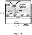
- the present invention describes the detection of fluorescence (luminescence, chemiluminescence, phosphorescence) signatures in the form of electrical signals in thin metallic films. Normally, fluorescence or luminescence emission is detected with a detector, PMT (Photomultiplier tube) or CCD (charge coupled device) camera etc. However, fluorophores in close proximity to the metal can induce currents in the metal, which can be detected using an ammeter as shown in Figure 1B .
- Fluorophore means any substance that can be excited by electromagnetic energy and induce a mirror dipole metallic surface in close proximity to the metallic surface and is intended to encompass a chemical or biochemical molecule or fragments thereof that is capable of interacting or reacting specifically with an analyte of interest in a sample to provide one or more optical signals. Additionally fluorophore includes both extrinsic and intrinsic fluorophores. Extrinsic fluorophore refer to fluorophores bound to another substance. Intrinsic fluorophores refer to substances that are fluorophores themselves. Exemplary fluorophores include but are not limited to those listed in the Molecular Probes Catalogue which is incorporated by reference herein.
- fluorophores include but are not limited to Alexa Fluor® 350, dansyl Chloride (DNS-Cl), 5-(iodoacetamida)fluoroscein (5-IAF); fluoroscein 5-isothiocyanate (FITC), tetramethylrhodamine 5-(and 6-)isothiocyanate (TRITC), 6-acryloyl-2-dimethylaminonaphthalene (acrylodan), 7-nitrobenzo-2-oxa-1,3,-diazol-4-yl chloride (NBD-Cl), ethidium bromide, Lucifer Yellow, 5-carboxyrhodamine 6G hydrochloride, Lissamine rhodamine B sulfonyl chloride, Texas RedTM.
- Alexa Fluor® 350 Dansyl Chloride (DNS-Cl), 5-(iodoacetamida)fluoroscein (5-IAF); fluoroscein 5-isothiocyanate
- naphthalamine sulfonic acids including but not limited to 1-anilinonaphthalene-8-sulfonic acid (ANS) and 6-(p-toluidinyl)naphthalen- e-2-sulfonic acid (TNS), Anthroyl fatty acid, DPH, Parinaric acid, TMA-DPH, Fluorenyl fatty acid, Fluorescein-phosphatidylethanolamine, Texas red-phosphatidylethanolamine, Pyrenyl-phophatidylcholine, Fluorenyl-phosphotidylcholine, Merocyanine 540, 1-(3-sulfonatopropyl)-4-[- .beta.-[2 [(di-n-butylamino)-6 naphthyl]vinyl]pyridinium betaine (Naphtyl Styryl), 3,3'dipropylthiadicar
- Representative intrinsic fluorophores include but are not limited to organic compounds having aromatic ring structures including but not limited to NADH, FAD, tyrosine, tryptophan, purines, pyrirmidines, lipids, fatty acids, nucleic acids, nucleotides, nucleosides, amino acids, proteins, peptides, DNA, RNA, sugars, and vitamins. Additional suitable fluorophores include enzyme-cofactors; lanthanide, green fluorescent protein, yellow fluorescent protein, red fluorescent protein, or mutants and derivates thereof.
- novel quaternary nitrogen heterocyclic boronic acid-containing compounds including:
- chemiluminescence labels or moieties which participate in light-producing reactions in the presence of a triggering agent or cofactor.
- a preferred embodiment will be discussed in terms of chemiluminescence labels and triggering agent.
- the label affixed to the detector molecule will be referred to as the "label” or "label agent”.
- label agent label agent
- triggering agent or cofactor is broadly used to describe any chemical species, other than the chemiluminescence labels which participate in a reaction and which produces a detectable response. Chemiluminescence labels and triggering agents produce a light response.
- chemiluminescence labels include but without limitation, peroxidase, bacterial luciferase, firefly luciferase, functionalized iron-porphyrin derivatives, luminal, isoluminol, acridinium esters, sulfonamide and others.
- a recent chemiluminescent label includes xanthine oxidase with hypoxanthine as substrate.
- the triggering agent contains perborate, a Fe-EDTA complex and luminol.
- Choice of the particular chemiluminescence labels depends upon several factors which include the cost of preparing labeled members, the method to be used for covalent coupling to the detector molecule, and the size of the detector molecules and/or chemiluminescence label. Correspondingly, the choice of chemiluminescence triggering agent will depend upon the particular chemiluminescence label being used.
- Chemiluminescent reactions have been intensely studied and are well documented in the literature.
- peroxidase is well suited for attachment to the detector molecule for use as a chemiluminescence.
- the triggering agent effective for inducing light emission in the first reaction would then comprise hydrogen peroxide and luminol.
- Other triggering agents which could also be used to induce a light response in the presence of peroxidase include isobutyraldehyde and oxygen.
- Procedures for labeling detector molecules, such as antibodies or antigens with peroxidase are known in the art.
- peroxidase-labeled antibodies or antigens peroxidase and antigens or antibodies are each reacted with N-succinimidyl 3-(2-pyridyldithio) proprionate (hereinafter SPDP) separately.
- SPDP-labeled peroxidase, or SPDP-labeled antigen or antibody is then reacted with dithiothreitol to produce thiol-labeled peroxidase, or thiol-labeled antigen or antibody.
- the thiol derivative is then allowed to couple with the SPDP-labeled antigen or antibody, or SPDP-labeled peroxidase.
- antibodies may be coupled covalently using glutaraldehyde to a silane derivative of borosilicate glass.
- biomolecule means any molecule occurring in nature or a derivative of such a molecule.
- the biomolecule can be in active or inactive form.
- Active form means the biomolecule is in a form that can perform a biological function.
- Active form means the biomolecule must be processed either naturally or synthetically before the biomolecule can perform a biological function.
- the biomolecule has a dipole moment when excited and thus can induce a mirror dipole in a metallic material in close proximity.
- biomolecules include nucleic acids, aromatic carbon ring structures, NADH, FAD, amino acids, carbohydrates, steroids, flavins, proteins, DNA, RNA, oligonucleotides, peptide, nucleic acids, fatty acids, myoglobin, sugar groups such as glucose etc., vitamins, cofactors, purines, pyrimidines, formycin, lipids, phytochrome, phytofluor, peptides, lipids, antibodies, bilirubin, tryptaphan and phycobiliproptein.
- the present invention may optionally include the use of microwave energy or sonic energy to increase any reaction rates in an assay detection system.
- the present invention can be used for points -of -care clinical assessment in emergency rooms.
- the present invention may optionally include the use of microwave energy or sonic energy to increase any reaction rates in an assay detection system
- the assay systems of the present invention may further comprise a light or laser source for directing an energy beam on any included fluorophore to provide excitation energy.
- the laser beam may be positioned adjacent to the system for directing the beam at the molecular components.
- the laser may be any device capable of focusing an energy beam at a particular point on the solid or liquid source material for excitation and the laser may transmit RF, infrared, microwave to UV energy.
- Any source known to one skilled in the art may be used, such as a laser that emits light, wherein light is used in its broad sense, meaning electromagnetic radiation which propagates through space and includes not only visible light, but also infrared and ultraviolet radiation.
- a single instrument placed above the surface of the assay can be used to generate the energy to excite fluorescing molecules.
- the light can be emitted from a fiber continuously or intermittently, as desired.
- 2-photon excitation may be used at approximately 375 to 900 nm using continuous or short pulse width ( ⁇ 50 ps), high repetition rate (> 1 MHz), laser diode sources.
- continuous or short pulse width ⁇ 50 ps
- high repetition rate > 1 MHz
- laser diode sources A variety of pulsed laser diode sources that will be compatible with fluorophores can be used with the present invention and are commercially available.
- the present invention can be used with tunable Ti:Sapphire laser excitation and multiphoton microscopy.
- the present invention provides for metallized islands of elliptical, spherical, triangular or rod-like forms.
- the elliptical islands have aspect ratios of 3/2, and the spherical colloids have diameters of 20-60 nm.
- the invention is not limited to any particular geometry. Using known coating techniques, the placement of metallic islands could be controlled precisely, as close as 10 to 50 nm apart.
- the metallic material may be in the form of a porous three dimensional matrix.
- the three dimensional matrix may be a nano-porous three dimensional matrix.
- the metallic material may include metal colloid particles and/or metal-silica composite particles.
- the metallic material may comprise agglomerated metal particles and/or binary linked particles or metal particles in a polymer matrix.
- the three dimensional matrix may be formed from controlled pore glasses or using matrices assembled from the aggregation of silver-silica composites themselves.
- the matrices may be metallic nanoporous matrix, through which species will flow and be both detected and counted more efficiently.
- the emission induction of a mirror dipole from the excited fluorophore to the metallic may be observed at distances according to the type of fluorophore to be detected and the type of metal. For example, induction of a current may be observed when a fluorophore distances about 5 nm to about 200 nm to metal surfaces. Preferable distances are about 5 nm to about 50 nm, and more preferably, 10 nm to about 30 nm to metal surfaces. At this scale, there are few phenomena that provide opportunities for new levels of sensing, manipulation, and control. In addition, devices at this scale may lead to dramatically enhanced performance, sensitivity, and reliability with dramatically decreased size, weight, and therefore cost.
- the island particles are prepared in clean beakers by reduction of metal ions using various reducing agents. For example, sodium hydroxide is added to a rapidly stirred silver nitrate solution forming a brown precipitate. Ammonium hydroxide is added to re-dissolve the precipitate. The solution is cooled and dried quartz slides are added to the beaker, followed by glucose. After stirring for 2 minutes, the mixture is warmed to 30°C. After 10-15 minutes, the mixture turns yellow-green and becomes cloudy. A thin film of silver particles has formed on the slides as can be seen from their brown green color. The slides are rinsed with pure water prior to use.
- sodium hydroxide is added to a rapidly stirred silver nitrate solution forming a brown precipitate.
- Ammonium hydroxide is added to re-dissolve the precipitate.
- the solution is cooled and dried quartz slides are added to the beaker, followed by glucose. After stirring for 2 minutes, the mixture is warmed to 30°C. After 10-15 minutes, the mixture turns yellow-
- Silver is primarily used because of the familiar color from the longer surface plasmon absorption of silver.
- Colloids can be prepared as suspensions by citrate reduction metals.
- Preferred metals are silver and gold. Again, gold may be because of the absorption of gold at shorter wavelengths. However, gold colloids may be used with longer wavelength red and NIR fluorophores.
- the size of the colloids and their homogeneity can be determined by the extensive publications on the optical properties of metal particles available and the effects of interface chemistry on the optical property of colloids.
- Silver island films can be formed by a chemical reduction of a silver salt on the quartz surface, which are relatively simple to fabricate. However, this approach does not provide a control of particle size, or distance of the fluorophores from the surface. Enhancements of 1000 fold have been with the realization that sample geometries have been heterogeneous and the enhancement factors spatially averaged.
- Metal particles can be bound to a surface by placing functional chemical groups such as cyanide (CN), amine (NH 2 ) or thiol (SH), on a glass or polymer substrate.
- Functional chemical groups such as cyanide (CN), amine (NH 2 ) or thiol (SH)
- CN cyanide
- NH 2 amine
- SH thiol
- Metallic colloids may also be incorporated into organic polymers, covalently or non-covalently, to form polymeric matrices, wherein the distance from diffusing species affords an increase in radiative decay rate and thus, an increase in quantum yield.
- Such polymeric matrices are ideal for sensing/flowing sensing applications of low concentration species.
- the electrode system of the present invention may include a containment vessel that includes two electrodes, anode and cathode, attached to the vessel or the electrode can be inserted into solution.
- the electrodes can be fabricated from any conductive metal and may include carbons, noble metals or alloys of Pt, Pd, Ir, Au, Ru, etc., noble metals or alloys deposited on a substrate such as Ti or Ta. Metals and metal alloys are preferred having a conductivity of greater than about 10 -4 S/cm.
- wire electrodes can be directly attached to two of the metallic particles, wherein the metallic particles and attached wires are separated sufficiently to detect optimal current flow.
- the electrodes can be fabricated from any electrically conducting polymer, electrically conducting ceramic, electrically conducting glass, or combinations thereof including metal oxides and selected from tin, lead, vanadium, titanium, ruthenium, tantalum, rhodium, osmium, iridium, iron, cobalt, nickel, copper, molybdenum, niobium, chromium, manganese, lanthanum, or lanthanum series metals or alloys or combinations thereof, and possibly containing additives like calcium to increase electrical conductivity.
- Electrolyte or polar solvents may include an ionically conductive aqueous or nonaqueous solution or material, which enhances the movement of current between electrodes.
- This embodiment of the present invention may also have vast applications in clinical medicine, environmental monitoring applications, homeland security such as rapid detection of low concentration species with a direct and digital readout, industrial processes, pharmaceutical industries such as monitoring species, and sensors for use in reduced atmospheres such as biohazard clean rooms and space light.
- fluorescence-based immunoassays In Traditional Fluorescence-based immunoassays, the extent of detected fluorophore (usually fluorescence intensity) is directly related to the analyte concentration to be determined in the assay.
- fluorescence-based immunoassays can be constructed on silvered surfaces, where the concentration of analyte (antigen) can be determined by the induced currents in the metal, as depicted by Figure 1A and Figure 2 .
- the reading is purely digital and is a direct measure of the coupled fluorescence.
- fluorescence based immunoassays in the world today detect the fluorescence from the assay directly, then covert the signal which can be displayed digitally.
- Figure 3A also demonstrates that the direction of current flow can be determined by the position of the excitation spot relative to the sampling electrode.
- the current is directly symmetrical, i.e. a positive or negative current, with regard to the position of the laser spot and the electrode.
- fluorophore coated substrates can induce currents in metal films after sun light illumination, Figure 4 .
- a Xenon arc lamp is used to simulate sun light.
- the current modulates, demonstrating that the effect is due to direct illumination of SiFs / fluorophores with light.
- Laser light also causes plasmonic current as shown in the bottom figure of Figure 4 .
- Figure 5 - top shows that dry Sifs (Silver Island Films) have little to no current in them when illuminated by an external light source, a value of 0 nA determined.
- a current of ⁇ 5 nA is produced.
- the current modulates as the Xe-arc lamp light source is modulated on-off.
- This background current is due to the water dipole interaction with the metal SiFs.
- a fluorophore fluorescent, phosphorescent or chemiluminescent species
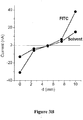
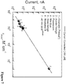
- the magnitude of the induced current is dependent on the molar extinction coefficient of the close-proximity dipole, Figure 7 , which implies that other plasmonics nanostructures will be excellent for inducing a larger magnitude current, see below, Figures 8-11 .
- Nanoparticles such as those comprised of gold, silver, copper, platinum, also work, as shown in Figures 8-11 .
- Figure 8 shows the simple assay constructed using both 20 and 40 nm gold colloids labeled to an antibody, which binds to immobilized antigen on SiFs coated surface. The plasmon absorption spectra of the antibody gold conjugate is shown in Figure 8 . When excited with a 473 nm laser line, current is induced in the SiFs, as shown in Figure 9 .
- the current is gated with the on-off gating of the laser source, demonstrating that the effect is due to light on the assay substrate which has been incubated with gold-colloid labeled antibody.
- the induced current is more significant than the current induced by fluorophores in the same assay system, Figure 10 . This is due to the fact, that a bigger dipole moment is observed with the colloid label as compared to a fluorophore label at the same excitation wavelength.
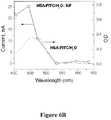
- the wavelength dependence of the current is a function of the absorption spectra of both the colloid labels as well as the Sifs (Silver Island Films) themselves, Figure 11 .
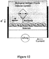
- Figures 12 and 13 show the use of an antibody that has a dipole moment and has the ability to induce mirror dipole in the metallic particles.
- many antigens only allow for a single antibody to bind to them so fluorescence is difficult to use for detection of these species.
- antibodies can be bound to surfaces for the capture of such antigens that has a dipole moment upon excitation can induce a dipole in the metallic material and thus induce a current. This will be very useful for applications where only one antibody can bind an antigen.
- a fluorophore can also be used as shown in Figure 13 .
Description
- The present invention is directed to a method that detects fluorescence, luminescence or phosphorescence signatures in the form of an electrical signal conducted in metallic structures.
- The identification and quantification of proteins and other biomolecules using bioassays are of great importance in biomedical and biochemical applications.1-3 Fluorescence is the dominant technology in most of these applications, where a biomolecule of interest is detected by fluorescence emission from its fluorophore labeled binding partner.4, 5 Fluorescence-based bioassays those carried out on planar surfaces generally lack sensitivity and require expensive optical instruments.6, 7 In addition, the biorecognition events in these assays are inherently slow (several minutes to hours).6, 7 The sensitivity of the fluorescence-based assays can be improved, without the use of high-end optical instruments, by incorporating plasmon resonant particles (PSPs) into these assays.8, 9 The improved sensitivity is made possible by the increase in fluorescence signatures and decreased lifetimes of fluorophores placed in close proximity to PSPs, described by a phenomenon called Metal-Enhanced Fluorescence (MEF).8, 10 In MEF-based bioassays, PSPs (generally silver nanoparticles) are deposited onto the planar surface and the bioassay is constructed on the PSPs.8 Since the size of most biomolecules are smaller than PSPs (20-100 nm), fluorophores are positioned within a distance where their emission is increased due to their interactions with the surface plasmons of PSPs.10
- The interactions of luminescent species with the close-proximity metallic nanoparticles have been extensively studied. These near-field interactions, are for the most part very complex, but can simply be understood phenomenologically as due to a close- proximity fluorophore inducing a mirror dipole in the metal, which in tum radiates the coupled quanta, in the form of emission,
Figure 1A . This interaction has been appropriately previously called "Metal-Enhanced Fluorescence". - For decades fluorescence-based technologies have relied on photo detectors to convert photon fluxes into digital signatures such as photomultiplier tube or charge coupled device (CCD) camera. Nearly all fluorescence based instruments encompass on or more of these types of detectors. However, such detectors are expensive and require an additional piece of equipment. Thus it would be advantageous to detect fluorescence without the need for such expensive detectors.
- Document "Surface plasmon enhanced photon drag in metal films" (Vengurlekar et al., Applied Phys. Lett. 87, 091118 (2005)) discloses a system comprising a Au thin film mounted in the Kretschmann-Raether geometry. In this system the photon drag effect is observed in the form of an electrical current induced by optical excitation.
- Document
WO 2006/138698 A2 discloses metal-enhanced fluorescence-based sensing methods. In this document, the emitted fluorescence is detected by a spectrometer. - The present invention relates to methods that detect fluorescence, luminescence or phosphorescence signatures in the form of an electrical signal conducted and emitted from metallic containing surfaces. Thus, the present invention provides for detecting fluorescence digitally and directly without the need for expensive detectors.
- According to the invention, a method is provided as defined in
claim 1. - It is described a system for generating electrical current, the system comprising:
- a substrate comprising metallic material positioned on the substrate, wherein the metallic material is shaped as particles, nanostructures, island or colloids and at least partially covered with a polar solution;
- a set of electrically conductive electrodes communicatively contacting at least two of the metallic particles positioned thereon;
- an intrinsic or extrinsic fluorophore positioned near the metallic material, wherein excitation of the fluorophore by electromagnetic energy induces a mirror dipole in the metallic material causing plasmonic current flow for storage or directing to a current reading device.
- Importantly the current is increased as the amount of binding fluorophores increases, thereby providing for an assay that provides an electrical signal proportional to the amount of binding fluorophores.
- It is also described an assay detection method comprising:
- providing a conductive metallic material on a substrate; wherein the metallic material is shaped as a non-continuous film, particles, nanostructures, island or colloids and wherein the substrate has a first end and an opposing second end;
- communicatively contacting the first and second end of the substrate and at least two of the metallic particles positioned thereon to a first and second electrode, wherein the first and second electrodes are communicatively connected to a current reading device;
- introducing at least one biomolecule for disposing near the conductive metallic material, wherein the biomolecule is capable of inducing a mirror dipole in the metallic material and such dipole is enhanced by a predetermined proximity to the metallic material;
- applying electromagnetic energy from an electromagnetic energy source to excite the biomolecule and inducing a mirror dipole in the metallic material causing plasmonic current flow; and
- measuring the plasmonic current flow by the current flow detector.
- The method and system described above may be used in multiple detecting systems, including but not limited to, immunoassays, hybridization assays, resonance energy transfer assays, polarization/anisotropy based assays, chemiluminescence based assays, luminescence based assays, enzyme-linked immunosorbent assays.
- It is also described a detection system comprising:
- a conductive metallic material positioned within a container, wherein the metallic material is shaped as a non-continuous film, particles, nanostructures, island or colloids, a conductive metallic material on a substrate;
- at least one fluorophore for disposing near the conductive metallic material, wherein the fluorophore is capable of inducing a mirror dipole in the metallic material and such dipole is enhanced by a predetermined proximity to the metallic material;
- a first and second electrode communicatively connected to at least two of the metallic particles positioned thereon, wherein the first and second electrodes are communicatively connected to a current reading device;
- an electromagnetic energy source to excite the fluorophore and to induce a mirror dipole in the metallic material causing plasmonic current flow, wherein electromagnetic energy source is positioned a distance from the first or second electrode to increase current to be detected by the current reading device.
- In the present example, the biomolecule comprises a fluorescing component that has the ability to fluoresce when contacted with radiation in the range from UV to IR.
- It is also described a method of metal-enhanced fluorescence sensing, comprising:
- applying a conductive metallic material to a surface used in a detection system, wherein the surface includes glass, quartz, or a polymeric material, wherein the surface has a first and second end, wherein the first and second end and at least some of the metallic material is communicatively connected to a first and second electrodes with a current measuring device positioned therebetween;
- introducing a polar solution containing at least one biomolecule for disposing near the conductive metallic surface, wherein the biomolecule is capable of excitation causing either a dipole moment or fluorescing;
- exciting the biomolecule with an electromagnetic source to cause the dipole moment or fluorescing and whereby such excitement induces a dipole in the metallic material causing plasmonic current flow;
- measuring the plasmonic current flow with the current reading device, such as an ammeter.
- Preferably, the electrodes are separated by a sufficient distance to provide optimal current readings, wherein the separation is from about from about 5mm to 100mm.
- It is also described a method for detecting a targeted pathogen in a sample without the use of a photodetector, the method comprising:
- providing a system comprising:
- an immobilized metallic material positioned on a surface substrate in a polar solution, wherein the substrate has a first and second end and wherein the first and second end of the substrate include electrodes or at least some metallic material are communicatively connected to a first and second electrode, wherein the immobilized metallic material has attached thereto an immobilized capture DNA sequence probe complementary to a known DNA sequence of the target pathogen; and
- a free capture DNA sequence probe complementary to a known DNA sequence of the target pathogen, wherein the free capture DNA sequence probe has attached thereto a fluorophore;
- contacting the sample with the immobilized capture DNA sequence probe, wherein any DNA sequence of the target pathogen binds to the immobilized capture DNA sequence probe;
- contacting the bound DNA sequence of the target pathogen with the free capture DNA sequence probe, wherein binding of the free capture DNA sequence probe to the DNA sequence of the target pathogen causes the fluorophore to be positioned a sufficient distance from the immobilized metallic material to induce a dipole in the metallic material;
- irradiating the system with electromagnetic energy in a range from UV to IR to excite the fluorophore positioned a predetermined distance from the metallic material; and
- measuring the plasmonic current flow with a current flow detector positioned between the electrodes, wherein the current is proportional to the amount of fluorophores.
- Preferably, the conductive metallic material takes the form of metallic particles, such as, nanostructures, islands, colloids, porous matrix or a semi-continuous metallic surface. The metallic element may include any form of metals such as silver, gold, platinum, zinc, aluminum, indium, palladium, rhodium iron, nickel and copper, and more preferably the metallic material is silver, such as a low-density silver. The substrate can include, glass, quartz and/or a polymeric material.
- Preferably, the metallic material is in the form of particles and separated a distance to provide optimal current flow and wherein resistance is higher than that of a continuous metal film. Preferably, at least a portion of each metallic particle is in contact with a polar solvent or a dipolar aprotic solvent that has a dipole moment and inducible, such as water, other polar solvents, including methanol or acetic acid, ionic salt solutions and/or acetone, ethylene acetate.
- The molecule that is capable of fluorescing and/or upon excitation by electromagnetic energy exhibits a dipole moment includes, but is not limited to fluorophores, chromophores, lumophores or biomolecules that include extrinsic luminescence activity.
- In one aspect, the present invention relates to bioassay systems comprising metallic surfaces for the enhancement of effects of chemiluminescence based reactions positioned near the metallic surfaces, wherein metallic surface plasmons are excited by a chemically induced electronically excited state of a chemiluminescent species and transference of energy from the chemiluminescence reaction induces plasmonic current flow in the metallic structures that can be measured with a current flow device.
- It is also described an assay, the method comprising:
- providing at least one vessel or container; wherein a first and second electrode are positioned within the vessel or communicatively connected thereto;
- introducing metallic nanostructures into the vessel, wherein the vessel includes a polar solution, wherein the metallic nanostructures can be free in solution or connected to a surface of the vessel and communicatively connected to the first and second electrodes;
- introducing a molecule that exhibits dipole activity upon excitation and disposing such molecule near the metallic nanostructures, wherein the metallic nanostructure is positioned a predetermined proximity to the metallic nanostructures to induce a mirror dipole in the metallic nanostructures; and
- measuring the current flow.
- It is also described a method of metal-enhanced chemiluminescence sensing, comprising:
- applying a metallic material to a surface used in a detection system, wherein the surface or metallic material is connected to a set of electrodes;
- introducing a solution containing at least one biomolecule for disposing near the metallic surface, wherein the biomolecule comprises a chemiluminescent label;
- triggering the chemiluminescent label to induce a chemically electronically excited state thereby generating metallic surface plasmons and inducing a mirror dipole in the metallic material and generating a current flow in the solution.
- It is also described a system for measuning chemiluminescence, the system comprising:
- a partially metalized surface positioned on a surface substrate, wherein the metalized surface is in contact with a polar solvent wherein the substrate or partially metalized is connected to a set of electrodes;
- a connector molecule attached to the partially metallized surface or near the partially metallized surface for binding or capture of a desired molecule in a testing sample;
- a detector molecule having an affinity for the desired molecule, wherein the detector molecule comprises a chemiluminescence label;
- a triggering component that chemically reacts with the chemiluminescence label to generate a chemically induced electronically exited state and induce a mirror dipole in the partially metallic surface and inducing a current flow in the polar solvent, wherein the current flow is measured and such flow is proportional to the amount of desired molecule in the testing sample.
- A system for conducting current, the system comprising:
- 1. metallic particles dispersed in a polar solution, wherein the metallic particles are adaptable for connecting to an intrinsic or extrinsic fluorophore molecule; and
- 2. a source of electromagnetic energy to deliver radiation in a range of UV to IR and in an amount sufficient to excite the fluorophore, wherein such excitation causes a mirror dipole in the metallic particles and induces current flow in the solution.
- Still further, it is described using the present concept of plasmonic electricity in combination with a microscope that can provide visual images and a direct digital readout of induced plasmonic current flow, wherein the system includes a substrate having metallic particle deposited thereon, wherein the substrate is a slide adapted for use in a microscope and the substrate or two of the metallic particles are adapted with electrodes and attached to a current reading device.
- Other aspects and advantages of the invention will be more fully apparent from the ensuing disclosure and appended claims.
-
-
Figure 1 shows graphical representation of the current interpretation of Metal- Enhanced Fluorescence (A), Plasmonic Current is due to coupling of excited fluorophore to the surface plasmons of silver nanoparticles (B), a electrode setup with attached ammeter for measuring current, F - Fluorophore, MEF - Metal-Enhanced Fluorescence, PC - Plasmonic Current, Ag- Silver nanoparticles. -
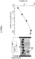
Figure 2 shows dependence of the plasmonic current (PC) in the SiF covered by rabbit IgG upon the concentration of added anti-IgG, labeled with fluorescein with graphical interpretation of the experiment. -
Figure 3A shows plasmonic current (PC) induced by the laser (473 nm) in SiF (R » 200 MOhm/cm) covered by FITC in water. The distance between electrodes is 10 mm. The excitation spot on SiF was moved from the left electrode to the right electrode. As shown inFigure 3B , the direction of observed plasmonic current flow, non-linearly depends on the distance of the excitation spot from the electrodes themselves. -
Figure 4 shows irradiation of FITC-SiFs (H2O) using a Xe-arc lamp and also a 473 nm laser. -
Figure 5 shows Top: Current induced in SiFs (dry sample); Middle: Current induced by wet SiFs (H2O); Bottom: SiFs coated with (FITC)-water solution. Irradiation of the slides was performed with a Xe-arc lamp. Manual light shut off was achieved sharply in about 5 sec intervals. SiF - Silver Island Films. -
Figures 6A andB show the dependence of the current, induced by light in SiF containing deposited human serum albumin labeled by FITC (HSA-FITC) or solvent (water), upon wavelength of excitation, (a) observed current corrected on Laser power deviations; (b) Contribution of the HSA-FITC to the current, absorption of the SiF and FITC. Excitation was done by lasers. Power of light generation was adjusted by the neutral filters (NF) to about 20-50 mW. Correction of the current at certain wavelengths was done by normalizing to the power of 46.5 mW (power of 473nm-Laser (500 mW) attenuated by N-filter (OD473 = 1.04 o.u.). [HSA-FITC]=0.65 mM in water, pH 5.5. -
Figure 7 shows the dependence of the current, generated by SiF-Dye system upon 473 nm laser irradiation, on extinction coefficient of the studied dyes. Observed current was normalized to the current induced by dyes at the Concentration of 150 mM, taking linear dependence of the current vs dye Concentration. -
Figure 8 shows the absorption spectra of 20 nm and 40 nm Gold conjugate anti-IgG (Rabbit). Insert: Graphical representation of the model immunological assay (IgG - anti-IgG) based on Plasmon Current (PC) upon light excitation. Ag - silver islands; Au - gold nanoparticle conjugated to anti-IgG. -
Figure 9 shows current induced in SiF-IgG covered with 40 nm Gold conjugate anti-IgG. lex was 473 nm and the concentration of Gold - anti-IgG was 0.1 nM. -
Figure 10 shows the dependences of the current, induced by the 473 nm laser in SiF-IgG slides, upon concentration of anti-IgG conjugates (20 nm and 40 nm Gold, or FITC). -
Figure 11 shows the dependence of the current in SiF-IgG slides, coated with 20 nm and 40 nm. Gold conjugates anti-IgG, upon the wavelength of excitation. Laser powers were normalized to ≈45 mW. -
Figure 12 shows the use of an antibody to detect a binding antigen wherein the binding antigen exhibits a dipole moment and induces dipole in the metallic particles thereby generating a current flow. -
Figure 13 shows the use of two antibodies wherein one captures the target antigen and the other provides for a fluorophore tag that upon excitation causes an induce dipole in the metallic material. - The present invention relates to methods for generating a current flow by positioning a fluorophore near a metallic particle and wherein excitation of the fluorophore causes an induced mirror dipole in the metallic particle and a flow of electrical current from one metallic particle to an adjacent metallic particle in communicative contact in a polar solvent.
- The present invention describes the detection of fluorescence (luminescence, chemiluminescence, phosphorescence) signatures in the form of electrical signals in thin metallic films. Normally, fluorescence or luminescence emission is detected with a detector, PMT (Photomultiplier tube) or CCD (charge coupled device) camera etc. However, fluorophores in close proximity to the metal can induce currents in the metal, which can be detected using an ammeter as shown in
Figure 1B . - The notion of direct detection of fluorescence is an enormous breakthrough in fluorescence spectroscopy and its applications. Potential uses for this technology include immunoassays, textiles and fabrics that provide metallic containing structures that can be used to powers hand held devices wherein the antigen concentration can now be read directly and most importantly digitally, as shown in
Figure 2 , without the need for an external detector. Another application is in solar energy conversion, where daylight excited fluorophores can generate electrical currents in thin metallic films. - "Fluorophore," as used herein, means any substance that can be excited by electromagnetic energy and induce a mirror dipole metallic surface in close proximity to the metallic surface and is intended to encompass a chemical or biochemical molecule or fragments thereof that is capable of interacting or reacting specifically with an analyte of interest in a sample to provide one or more optical signals. Additionally fluorophore includes both extrinsic and intrinsic fluorophores. Extrinsic fluorophore refer to fluorophores bound to another substance. Intrinsic fluorophores refer to substances that are fluorophores themselves. Exemplary fluorophores include but are not limited to those listed in the Molecular Probes Catalogue which is incorporated by reference herein.
- Representative fluorophores include but are not limited to Alexa Fluor® 350, Dansyl Chloride (DNS-Cl), 5-(iodoacetamida)fluoroscein (5-IAF); fluoroscein 5-isothiocyanate (FITC), tetramethylrhodamine 5-(and 6-)isothiocyanate (TRITC), 6-acryloyl-2-dimethylaminonaphthalene (acrylodan), 7-nitrobenzo-2-oxa-1,3,-diazol-4-yl chloride (NBD-Cl), ethidium bromide, Lucifer Yellow, 5-carboxyrhodamine 6G hydrochloride, Lissamine rhodamine B sulfonyl chloride, Texas Red™. sulfonyl chloride, BODIPY™., naphthalamine sulfonic acids including but not limited to 1-anilinonaphthalene-8-sulfonic acid (ANS) and 6-(p-toluidinyl)naphthalen- e-2-sulfonic acid (TNS), Anthroyl fatty acid, DPH, Parinaric acid, TMA-DPH, Fluorenyl fatty acid, Fluorescein-phosphatidylethanolamine, Texas red-phosphatidylethanolamine, Pyrenyl-phophatidylcholine, Fluorenyl-phosphotidylcholine, Merocyanine 540, 1-(3-sulfonatopropyl)-4-[- .beta.-[2 [(di-n-butylamino)-6 naphthyl]vinyl]pyridinium betaine (Naphtyl Styryl), 3,3'dipropylthiadicarbocyanine (diS-C3-(5)), 4-(p-dipentyl aminostyryl)-1-methylpyridinium (di-5-ASP), Cy-3 lodo Acetamide, Cy-5-N-Hydroxysuccinimide, Cy-7-Isothiocyanate, rhodamine 800, IR-125, Thiazole Orange, Azure B, Nile Blue, Al Phthalocyanine, Oxaxine 1, 4', 6-diamidino-2-phenylindole (DAPI), Hoechst 33342, TOTO, Acridine Orange, Ethidium Homodimer, N(ethoxycarbonylmethyl)-6-methoxyquinolinium (MQAE), Fura-2, Calcium Green, Carboxy SNARF-6, BAPTA, coumarin, phytofluors, Coronene, green fluorescent proteins and metal-ligand complexes.
- Representative intrinsic fluorophores include but are not limited to organic compounds having aromatic ring structures including but not limited to NADH, FAD, tyrosine, tryptophan, purines, pyrirmidines, lipids, fatty acids, nucleic acids, nucleotides, nucleosides, amino acids, proteins, peptides, DNA, RNA, sugars, and vitamins. Additional suitable fluorophores include enzyme-cofactors; lanthanide, green fluorescent protein, yellow fluorescent protein, red fluorescent protein, or mutants and derivates thereof.
- Also included are novel quaternary nitrogen heterocyclic boronic acid-containing compounds including:
- (A)

- (B)

- (C)

- (D)

- (E)

- (F)

- Examples of the present description are applicable to chemiluminescence labels or moieties which participate in light-producing reactions in the presence of a triggering agent or cofactor. In the present description, a preferred embodiment will be discussed in terms of chemiluminescence labels and triggering agent. The label affixed to the detector molecule will be referred to as the "label" or "label agent". For purposes herein, "triggering agent or cofactor" is broadly used to describe any chemical species, other than the chemiluminescence labels which participate in a reaction and which produces a detectable response. Chemiluminescence labels and triggering agents produce a light response.
- Examples of suitable chemiluminescence labels include but without limitation, peroxidase, bacterial luciferase, firefly luciferase, functionalized iron-porphyrin derivatives, luminal, isoluminol, acridinium esters, sulfonamide and others. A recent chemiluminescent label includes xanthine oxidase with hypoxanthine as substrate. The triggering agent contains perborate, a Fe-EDTA complex and luminol. Choice of the particular chemiluminescence labels depends upon several factors which include the cost of preparing labeled members, the method to be used for covalent coupling to the detector molecule, and the size of the detector molecules and/or chemiluminescence label. Correspondingly, the choice of chemiluminescence triggering agent will depend upon the particular chemiluminescence label being used.
- Chemiluminescent reactions have been intensely studied and are well documented in the literature. For example, peroxidase is well suited for attachment to the detector molecule for use as a chemiluminescence. The triggering agent effective for inducing light emission in the first reaction would then comprise hydrogen peroxide and luminol. Other triggering agents which could also be used to induce a light response in the presence of peroxidase include isobutyraldehyde and oxygen.
- Procedures for labeling detector molecules, such as antibodies or antigens with peroxidase are known in the art. For example, to prepare peroxidase-labeled antibodies or antigens, peroxidase and antigens or antibodies are each reacted with N-succinimidyl 3-(2-pyridyldithio) proprionate (hereinafter SPDP) separately. SPDP-labeled peroxidase, or SPDP-labeled antigen or antibody is then reacted with dithiothreitol to produce thiol-labeled peroxidase, or thiol-labeled antigen or antibody. The thiol derivative is then allowed to couple with the SPDP-labeled antigen or antibody, or SPDP-labeled peroxidase.
- Techniques for attaching antibodies or antigens to solid substrates are also well known in the art. For example, antibodies may be coupled covalently using glutaraldehyde to a silane derivative of borosilicate glass.
- The term "biomolecule" means any molecule occurring in nature or a derivative of such a molecule. The biomolecule can be in active or inactive form. "Active form" means the biomolecule is in a form that can perform a biological function. "Inactive form" means the biomolecule must be processed either naturally or synthetically before the biomolecule can perform a biological function. Preferably, the biomolecule has a dipole moment when excited and thus can induce a mirror dipole in a metallic material in close proximity. Exemplary biomolecules include nucleic acids, aromatic carbon ring structures, NADH, FAD, amino acids, carbohydrates, steroids, flavins, proteins, DNA, RNA, oligonucleotides, peptide, nucleic acids, fatty acids, myoglobin, sugar groups such as glucose etc., vitamins, cofactors, purines, pyrimidines, formycin, lipids, phytochrome, phytofluor, peptides, lipids, antibodies, bilirubin, tryptaphan and phycobiliproptein.
- There are many important assays that can directly benefit from immediate readouts and quicker kinetics. For example, myoglobin concentrations for heart attack patients, patients of toxic shock and pancreatitis. Thus, the present invention may optionally include the use of microwave energy or sonic energy to increase any reaction rates in an assay detection system. As such, the present invention can be used for points -of -care clinical assessment in emergency rooms.
- The present invention may optionally include the use of microwave energy or sonic energy to increase any reaction rates in an assay detection system
- The assay systems of the present invention may further comprise a light or laser source for directing an energy beam on any included fluorophore to provide excitation energy. The laser beam may be positioned adjacent to the system for directing the beam at the molecular components. The laser may be any device capable of focusing an energy beam at a particular point on the solid or liquid source material for excitation and the laser may transmit RF, infrared, microwave to UV energy.
- Any source, known to one skilled in the art may be used, such as a laser that emits light, wherein light is used in its broad sense, meaning electromagnetic radiation which propagates through space and includes not only visible light, but also infrared and ultraviolet radiation. Thus, a single instrument placed above the surface of the assay can be used to generate the energy to excite fluorescing molecules. The light can be emitted from a fiber continuously or intermittently, as desired.
- Further, 2-photon excitation may be used at approximately 375 to 900 nm using continuous or short pulse width (< 50 ps), high repetition rate (> 1 MHz), laser diode sources. A variety of pulsed laser diode sources that will be compatible with fluorophores can be used with the present invention and are commercially available.
- Still further, the present invention can be used with tunable Ti:Sapphire laser excitation and multiphoton microscopy.
- The present invention provides for metallized islands of elliptical, spherical, triangular or rod-like forms. In exemplary cases, the elliptical islands have aspect ratios of 3/2, and the spherical colloids have diameters of 20-60 nm. However, the invention is not limited to any particular geometry. Using known coating techniques, the placement of metallic islands could be controlled precisely, as close as 10 to 50 nm apart.
- The metallic material may be in the form of a porous three dimensional matrix. The three dimensional matrix may be a nano-porous three dimensional matrix. The metallic material may include metal colloid particles and/or metal-silica composite particles. The metallic material may comprise agglomerated metal particles and/or binary linked particles or metal particles in a polymer matrix. The three dimensional matrix may be formed from controlled pore glasses or using matrices assembled from the aggregation of silver-silica composites themselves. The matrices may be metallic nanoporous matrix, through which species will flow and be both detected and counted more efficiently.
- The emission induction of a mirror dipole from the excited fluorophore to the metallic may be observed at distances according to the type of fluorophore to be detected and the type of metal. For example, induction of a current may be observed when a fluorophore distances about 5 nm to about 200 nm to metal surfaces. Preferable distances are about 5 nm to about 50 nm, and more preferably, 10 nm to about 30 nm to metal surfaces. At this scale, there are few phenomena that provide opportunities for new levels of sensing, manipulation, and control. In addition, devices at this scale may lead to dramatically enhanced performance, sensitivity, and reliability with dramatically decreased size, weight, and therefore cost.
- Different surface enhanced fluorescence effects are expected for mirrors, sub-wavelength or semi-transparent metal surfaces, silver island films or metal colloids. More dramatic effects are typically observed for islands and colloids as compared to continuous metallic surfaces. The silver islands had the remarkable effect of increasing the intensity 5-fold while decreasing the lifetime 100-fold. Such an effect can only be explained by an increase in the radiative decay rate.
- The island particles are prepared in clean beakers by reduction of metal ions using various reducing agents. For example, sodium hydroxide is added to a rapidly stirred silver nitrate solution forming a brown precipitate. Ammonium hydroxide is added to re-dissolve the precipitate. The solution is cooled and dried quartz slides are added to the beaker, followed by glucose. After stirring for 2 minutes, the mixture is warmed to 30°C. After 10-15 minutes, the mixture turns yellow-green and becomes cloudy. A thin film of silver particles has formed on the slides as can be seen from their brown green color. The slides are rinsed with pure water prior to use.
- Alternative procedures for preparing metal particles are also available. Silver is primarily used because of the familiar color from the longer surface plasmon absorption of silver.
- Colloids can be prepared as suspensions by citrate reduction metals. Preferred metals are silver and gold. Again, gold may be because of the absorption of gold at shorter wavelengths. However, gold colloids may be used with longer wavelength red and NIR fluorophores.
- The size of the colloids and their homogeneity can be determined by the extensive publications on the optical properties of metal particles available and the effects of interface chemistry on the optical property of colloids.
- Silver island films can be formed by a chemical reduction of a silver salt on the quartz surface, which are relatively simple to fabricate. However, this approach does not provide a control of particle size, or distance of the fluorophores from the surface. Enhancements of 1000 fold have been with the realization that sample geometries have been heterogeneous and the enhancement factors spatially averaged.
- Metal particles can be bound to a surface by placing functional chemical groups such as cyanide (CN), amine (NH2) or thiol (SH), on a glass or polymer substrate. Metal colloids are known to spontaneously bind to such surfaces with high affinity.90, 91, 92
- Metallic colloids (or various other non-spherical shapes/particles) may also be incorporated into organic polymers, covalently or non-covalently, to form polymeric matrices, wherein the distance from diffusing species affords an increase in radiative decay rate and thus, an increase in quantum yield. Such polymeric matrices are ideal for sensing/flowing sensing applications of low concentration species.
- The electrode system of the present invention may include a containment vessel that includes two electrodes, anode and cathode, attached to the vessel or the electrode can be inserted into solution. Generally the electrodes can be fabricated from any conductive metal and may include carbons, noble metals or alloys of Pt, Pd, Ir, Au, Ru, etc., noble metals or alloys deposited on a substrate such as Ti or Ta. Metals and metal alloys are preferred having a conductivity of greater than about 10-4 S/cm. In the alternative, wire electrodes can be directly attached to two of the metallic particles, wherein the metallic particles and attached wires are separated sufficiently to detect optimal current flow.
- Further, the electrodes can be fabricated from any electrically conducting polymer, electrically conducting ceramic, electrically conducting glass, or combinations thereof including metal oxides and selected from tin, lead, vanadium, titanium, ruthenium, tantalum, rhodium, osmium, iridium, iron, cobalt, nickel, copper, molybdenum, niobium, chromium, manganese, lanthanum, or lanthanum series metals or alloys or combinations thereof, and possibly containing additives like calcium to increase electrical conductivity.
- Electrolyte or polar solvents may include an ionically conductive aqueous or nonaqueous solution or material, which enhances the movement of current between electrodes.
- This embodiment of the present invention may also have vast applications in clinical medicine, environmental monitoring applications, homeland security such as rapid detection of low concentration species with a direct and digital readout, industrial processes, pharmaceutical industries such as monitoring species, and sensors for use in reduced atmospheres such as biohazard clean rooms and space light.
- When a fluorophore induces a mirror dipole in the metal, near-field photo-induced currents (photo currents) are formed. These very small currents are able to migrate across silvered films. Interestingly, the greater the concentration of fluorophore present, there is a corresponding increase in induced current.
Figure 3 , shows the extent of photo -induced current on the concentration of fluorescein (a fluorescent probe) in water, placed between 2 electrodes on a silver island film. Remarkably, the current increases significantly over the 3 log10 concentrations of fluorescent probe studied. This result suggests that the more fluorophore present close to metal, then the greater the induced current flow. It is interesting to note, that in Traditional Fluorescence-based immunoassays, the extent of detected fluorophore (usually fluorescence intensity) is directly related to the analyte concentration to be determined in the assay. The results shown herein suggest, that fluorescence-based immunoassays can be constructed on silvered surfaces, where the concentration of analyte (antigen) can be determined by the induced currents in the metal, as depicted byFigure 1A andFigure 2 . Remarkably, the reading is purely digital and is a direct measure of the coupled fluorescence. In contrast, fluorescence based immunoassays in the world today, detect the fluorescence from the assay directly, then covert the signal which can be displayed digitally. Subsequently, the present approach is a significant breakthrough in how fluorescence is measured and quantified.Figure 3A also demonstrates that the direction of current flow can be determined by the position of the excitation spot relative to the sampling electrode. The current is directly symmetrical, i.e. a positive or negative current, with regard to the position of the laser spot and the electrode. - While direct measurement of fluorescence-based signatures is a big field (business) in itself, one very promising application of the technology is likely to be in solar energy conversion. It is also envisioned that fluorophore coated substrates can induce currents in metal films after sun light illumination,
Figure 4 . In this figure, a Xenon arc lamp is used to simulate sun light. As can be seen inFigure 4 - top, insert, as the sun light is gated on and off, the current modulates, demonstrating that the effect is due to direct illumination of SiFs / fluorophores with light. Laser light also causes plasmonic current as shown in the bottom figure ofFigure 4 . -
Figure 5 - top shows that dry Sifs (Silver Island Films) have little to no current in them when illuminated by an external light source, a value of 0 nA determined. However, when an aqueous solution is placed on top of the SiFs a current of < 5 nA is produced. Interestingly, the current modulates as the Xe-arc lamp light source is modulated on-off. This background current is due to the water dipole interaction with the metal SiFs. However, when a fluorophore (fluorescent, phosphorescent or chemiluminescent species) is added to the water solution on SiFs, a significant current is further observed, increasing to as much as 30 nA. This current is due to interaction of the fluorophore dipole with the metal, as graphically indicated inFigure 1B . As can be seen from this figure, the presence of fluorophores close to Sifs (and indeed other metals) causes a current, which is directly proportional to the concentration of fluorophore, making it an excellent technology for the direct detection of Fluorescence. In addition and remarkably, the current generation in the metal is wavelength dependent and appears to follow both the absorption spectra of the Sifs and the emission spectra of the metal, as shown inFigure 6A and B . In addition, the magnitude of the induced current is dependent on the molar extinction coefficient of the close-proximity dipole,Figure 7 , which implies that other plasmonics nanostructures will be excellent for inducing a larger magnitude current, see below,Figures 8-11 . - In addition to Fluorescent species, using non-fluorescent species have been considered as labels to induce current in metals. Nanoparticles such as those comprised of gold, silver, copper, platinum, also work, as shown in
Figures 8-11 .Figure 8 shows the simple assay constructed using both 20 and 40 nm gold colloids labeled to an antibody, which binds to immobilized antigen on SiFs coated surface. The plasmon absorption spectra of the antibody gold conjugate is shown inFigure 8 . When excited with a 473 nm laser line, current is induced in the SiFs, as shown inFigure 9 . The current is gated with the on-off gating of the laser source, demonstrating that the effect is due to light on the assay substrate which has been incubated with gold-colloid labeled antibody. Remarkably, the induced current is more significant than the current induced by fluorophores in the same assay system,Figure 10 . This is due to the fact, that a bigger dipole moment is observed with the colloid label as compared to a fluorophore label at the same excitation wavelength. Interestingly, and similar to fluorophores, the wavelength dependence of the current is a function of the absorption spectra of both the colloid labels as well as the Sifs (Silver Island Films) themselves,Figure 11 . -
Figures 12 and13 show the use of an antibody that has a dipole moment and has the ability to induce mirror dipole in the metallic particles. Notably many antigens only allow for a single antibody to bind to them so fluorescence is difficult to use for detection of these species. However, antibodies can be bound to surfaces for the capture of such antigens that has a dipole moment upon excitation can induce a dipole in the metallic material and thus induce a current. This will be very useful for applications where only one antibody can bind an antigen. A fluorophore can also be used as shown inFigure 13 . - Applications of Plasmonics electricity Technology:
- The present description provides for multiple uses of plasmonic electricity including:
- As a direct measure of Fluorescence, phosphorescence or chemiluminescence signatures.
- To provide digital read out of the above, without the need for additional analogue to digital conversion processes.
- In immunoassays, as a direct measurement of surface analytes by measuring induced current and not fluorescence or another luminescence signature.
- As a new class of detectors, directly converting fluorescence to electricity.
- In solar powering devices, with or without fluorophores or other nanoparticle labels.
- To enable immunoassays to be self powering away from a wall socket.
- In multiplexed and high throughput screening applications.
- As devices for converting light into electricity for electronic circuits.
- In DNA assays, as a direct measure of a DNA hybridization event.
- In RNA assays, to directly measure current from RNA assays, after hybridization.
- In chemiluminescence assays, using Horse Radish Peroxidase substrates.
- As a technology to measure distance of a fluorescence (or other dipole) from a metallic substrate.
- In light emitting diode constructs.
- As a technology for eliminating fluorescence detection optics in fluorescence based immunoassays, one simply measures the induced current and does not bother to measure the fluorescence using a different detector, optics and filters.
- Conductive materials such as textiles used for charging or powering hand held devices, such as radios, ipods and communication devices.
- Conductive textiles attached to a self cooling device or to provide for color alteration of the textile.
- (1) Collings, F. B.; Vaidya, V. S. Toxicology 2008, 245, 167-174.
- (2) Lalvani, A.; Meroni, P. L.; Millington, K. A.; Modolo, M. L.; Plebani, M.; Tincani, A.; Villalta, D.; Doria, A.; Ghirardello, A. Clin Exp Rheumatol 2008, 26, S62-66.
- (3) Taipa, M. A. Comb Chem High Throughput Screen 2008, 11, 325-335.
- (4) Enander, K.; Choulier, L.; Olsson, A. L.; Yushchenko, D. A.; Kanmert, D.; Klymchenko, A. S.; Demchenko, A. P.; Mely, Y.; Altschuh, D. Bioconjug Chem 2008 .
- (5) Schultz, E.; Galland, R.; Du Bouetiez, D.; Flahaut, T.; Planat-Chretien, A.; Lesbre, F.; Hoang, A.; Volland, H.; Perraut, F. Biosens Bioelectron 2008, 23, 987-994.
- (6) Matveeva, E.; Gryczynski, Z.; Gryczynski, I.; Malicka, J.; Lakowicz, J. R. Analytical Chemistry 2004, 76, 6287-6292.
- (7) Matveeva, E.; Malicka, J.; Gryczynski, I.; Gryczynski, Z.; Lakowicz, J. R. Biochem Biophys Res Commun 2004, 313, 721-726.
- (8) Asian, K.; Gryczynski, I.; Malicka, J.; Matveeva, E.; Lakowicz, J. R.; Geddes, C. D. Current Opinion in Biotechnology 2005, 16, 55-62.
- (9) Asian, K.; Lakowicz, J. R.; Szmacinski, H.; Geddes, C. D. Journal of .
- (10) Geddes, C. D.; Lakowicz, J. R. Journal of Fluorescence 2002, 12, 121-129.
- (11) Asian, K.; Geddes, C. D. Analytical Chemistry 2005, 77, 8057-8067.
- (12) Asian, K.; Zhang, Y.; Hibbs, S.; Baillie, L.; Previte, M. J.; Geddes, C. D. Analyst 2007, 132, 1130-1138.
- (13) Asian, K.; Holley, P.; Geddes, C. D. Journal of Immunological Methods 2006, 312, 137-147.
- (14) Thornycroft, L. H.; Barnaby, S. W. Min. Proc. Inst. Chem. Eng, 1895, 122 51-69.
- (15) Suslick, K. S. Science 1990, 247, 1439-1445.
- (16) Gould, R. K.; Coakley, W. T.; Grundy, M. A. .
- (17) Suslick, K. S.; Flannigan, D. J. Annu Rev Phys Chem 2008, 59, 659-683.
- (18) Neppiras, E. A. Phys. Rep. 1980, 61, 159-251.
- (19) Asian, K.; Leonenko, Z.; Lakowicz, J. R.; Geddes, C. D. Journal of .
- (20) Lofas, S.; Malmqvist, M.; Ronnberg, I.; Stenberg, E.; Liedberg, B.; Lundstrom, I. Sensors and Actuators B-.
Claims (8)
- An assay method to determine a concentration of an analyte in a sample, said method comprising:providing a conductive metallic material on a substrate, wherein the metallic material is shaped as metallic particles, nanostructures, islands or colloids, wherein the metallic particles, nanostructures, islands or colloids are separated from about 10 to 50 nm apart, wherein at least a portion of the metallic material is in contact with a polar solvent and wherein the substrate has a first end and an opposing second end;connecting the first and second end of the substrate and at least some of the metallic particles, nanostructures, islands or colloids positioned thereon to a first and second electrode, wherein the first and second electrodes are connected to a current reading device;introducing at least one intrinsic or extrinsic fluorophore for disposing near the metallic material, wherein the intrinsic or extrinsic fluorophore is capable of interacting or reacting with the analyte to provide one or more optical signals, and wherein excitation of the intrinsic or extrinsic fluorophore by electromagnetic energy induces a mirror dipole in the metallic material and such mirror dipole in the metallic material is enhanced by a predetermined proximity to the intrinsic or extrinsic fluorophore;applying electromagnetic energy from an electromagnetic energy source to excite the intrinsic or extrinsic fluorophore and inducing a mirror dipole in the metallic material causing electrical current flow; andmeasuring the electrical current flow by a current flow detector,wherein the concentration of analyte in the sample is determined from the induced electrical current in the metallic material.
- The assay method of claim 1, wherein the metallic material is selected from the group consisting of silver, gold, platinum, zinc, aluminum and copper.
- The assay method of claim 1, wherein the substrate includes glass, quartz, or a polymeric material.
- The assay method of claim 1, wherein the intrinsic or extrinsic fluorophore has the ability to fluoresce when contacted with radiation in the range from UV to IR.
- The assay method of claim 1, wherein the assay method is used for hybridization assays, resonance energy transfer assays, polarization/anisotropy based assays, luminescence based assays, and enzyme-linked immunosorbent assays.
- The assay method of claim 1, wherein the detected electrical current is proportional to the concentration of fluorophore.
- The assay method of claim 1, wherein the metallic material comprises silver.
- The assay method of claim 1, wherein the electromagnetic energy source is positioned a distance from the first or second electrode to increase current to be detected by the current reading device.
Applications Claiming Priority (2)
| Application Number | Priority Date | Filing Date | Title |
|---|---|---|---|
| US9778208P | 2008-09-17 | 2008-09-17 | |
| PCT/US2009/057282 WO2010033677A2 (en) | 2008-09-17 | 2009-09-17 | Plasmonic electricity |
Publications (3)
| Publication Number | Publication Date |
|---|---|
| EP2344866A2 EP2344866A2 (en) | 2011-07-20 |
| EP2344866A4 EP2344866A4 (en) | 2014-04-02 |
| EP2344866B1 true EP2344866B1 (en) | 2019-09-04 |
Family
ID=42040128
Family Applications (1)
| Application Number | Title | Priority Date | Filing Date |
|---|---|---|---|
| EP09815179.8A Not-in-force EP2344866B1 (en) | 2008-09-17 | 2009-09-17 | Plasmonic electricity |
Country Status (5)
| Country | Link |
|---|---|
| US (1) | US8618505B2 (en) |
| EP (1) | EP2344866B1 (en) |
| CN (1) | CN102216757B (en) |
| CA (1) | CA2739309C (en) |
| WO (1) | WO2010033677A2 (en) |
Families Citing this family (15)
| Publication number | Priority date | Publication date | Assignee | Title |
|---|---|---|---|---|
| US9500590B2 (en) | 2006-02-13 | 2016-11-22 | University Of Maryland, Baltimore County | Assays for pathogen detection using microwaves for lysing and accelerating metal-enhanced fluorescence |
| WO2011143288A2 (en) | 2010-05-11 | 2011-11-17 | University Of Maryland, Baltimore County | Tuning of metal enhanced emissions of long-lived luminescent compounds |
| WO2010096414A2 (en) | 2009-02-17 | 2010-08-26 | University Of Maryland Biotechnology Institute | Metal-enhanced bioluminescence: an approach for monitoring biological bioluminescent processes |
| EP2399117A4 (en) | 2009-02-23 | 2012-08-08 | Univ Maryland | Directional surface plasmon coupled fluorescence and chemiluminescence from thin films of nickel, iron or palladium and uses thereof |
| EP2504687B1 (en) | 2009-11-25 | 2017-04-05 | University of Maryland, Baltimore County | System for detecting metal enhanced fluorescence from metallic nanoburger structures |
| US9810637B2 (en) | 2009-12-14 | 2017-11-07 | University Of Maryland, Baltimore County | Plasmonic electricity |
| EP2513630B1 (en) | 2009-12-17 | 2016-05-25 | Chris Geddes | A detection system using mixed-metal substrates for metal-enhanced fluorescence |
| EP2686683A4 (en) | 2011-03-18 | 2014-10-01 | Chris Geddes | Metal-enhanced photoluminescence from carbon nanodots |
| US8735175B2 (en) | 2011-03-18 | 2014-05-27 | Chris D. Geddes | Multicolor microwave-accelerated metal-enhanced fluorescence (M-MAMEF) |
| US9244012B2 (en) | 2011-09-26 | 2016-01-26 | University Of Maryland, Baltimore County | Enhanced luminescence from nanopolished surfaces and plate wells |
| US9816990B2 (en) | 2013-02-28 | 2017-11-14 | University Of Maryland, Baltimore County | Ultra-fast pathogen toxin detection assay based on microwave-accelerated metal-enhanced fluorescence |
| EP3718625A1 (en) * | 2013-05-21 | 2020-10-07 | Nederlandse Organisatie voor toegepast- natuurwetenschappelijk Onderzoek TNO | Chemical conversion process |
| US10379050B2 (en) | 2015-01-13 | 2019-08-13 | University Of Maryland, Baltimore County | Spectral shifts and modifications in metal-enhanced fluorescence, phosphorescence and alpha-fluorescence |
| US10294451B2 (en) | 2015-04-22 | 2019-05-21 | University Of Maryland, Baltimore County | Flow and static lysing systems and methods for ultra-rapid isolation and fragmentation of biological materials by microwave irradiation |
| WO2017015531A1 (en) | 2015-07-22 | 2017-01-26 | University Of Maryland, Baltimore County | Hydrophilic coatings of plasmonic metals to enable low volume metal-enhanced fluorescence |
Citations (1)
| Publication number | Priority date | Publication date | Assignee | Title |
|---|---|---|---|---|
| WO2006138698A2 (en) * | 2005-06-17 | 2006-12-28 | University Of Maryland Biotechnology Institute | Metal-enhanced fluorescence-based sensing methods |
Family Cites Families (32)
| Publication number | Priority date | Publication date | Assignee | Title |
|---|---|---|---|---|
| US5017009A (en) | 1986-06-26 | 1991-05-21 | Ortho Diagnostic Systems, Inc. | Scattered total internal reflectance immunoassay system |
| GB8807488D0 (en) | 1988-03-29 | 1988-05-05 | Ares Serono Res & Dev Ltd | Method of assay |
| CA2076709A1 (en) | 1992-08-24 | 1994-02-25 | Ulrich J. Krull | Amplified fluorescence emission for chemical transduction |
| AT403961B (en) | 1995-03-17 | 1998-07-27 | Avl Verbrennungskraft Messtech | OPTOCHEMICAL MEASURING SYSTEM WITH A FLUORESCENCE SENSOR |
| US5841143A (en) * | 1997-07-11 | 1998-11-24 | The United States Of America As Represented By Administrator Of The National Aeronautics And Space Administration | Integrated fluorescene |
| WO2002029076A1 (en) | 2000-10-03 | 2002-04-11 | Mirari Biosciences, Inc. | Methods and compositions for directed microwave chemistry |
| US7348182B2 (en) | 2000-10-03 | 2008-03-25 | Mirari Biosciences, Inc. | Directed microwave chemistry |
| AU2003221788A1 (en) | 2002-04-30 | 2003-11-17 | University Of Maryland, Baltimore | Fluorescence sensing |
| US7095502B2 (en) | 2002-08-06 | 2006-08-22 | Joseph Lakowicz | Optical structures for metal-enhanced sensing |
| AU2003268537A1 (en) | 2002-09-10 | 2004-04-30 | University Of Maryland, Baltimore | Use of metallic particles to improve fluorescence imaging |
| ATE479775T1 (en) | 2002-11-26 | 2010-09-15 | Univ Maryland Biotechnology | HIGHLY SENSITIVE ASSAY FOR PATHOGENE DETECTION USING METAL ENHANCED FLUORESCENCE |
| US20050053974A1 (en) | 2003-05-20 | 2005-03-10 | University Of Maryland | Apparatus and methods for surface plasmon-coupled directional emission |
| EP1644330B1 (en) | 2003-06-27 | 2011-08-17 | The University Of Maryland | Quaternary nitrogen heterocyclic compounds for detecting aqueous monosaccharides in physiological fluids |
| EP1671118B1 (en) | 2003-09-17 | 2011-11-02 | University of Maryland, Baltimore County | Cyanide sensing compounds and uses thereof |
| FR2860872A1 (en) * | 2003-10-09 | 2005-04-15 | Commissariat Energie Atomique | MICRO-SENSORS AND NANO-SENSORS OF CHEMICAL AND BIOLOGICAL SPECIES WITH SURFACE PLASMONS |
| US7253452B2 (en) | 2004-03-08 | 2007-08-07 | Massachusetts Institute Of Technology | Blue light emitting semiconductor nanocrystal materials |
| WO2005114748A2 (en) * | 2004-04-13 | 2005-12-01 | Solaris Nanosciences, Inc. | Plasmon enhanced sensitized photovoltaic cells |
| CA2628056C (en) | 2004-11-05 | 2013-05-28 | University Of Maryland Biotechnology Institute | Metal-enhanced fluorescence from plastic substrates |
| CA2629447C (en) | 2004-11-19 | 2012-09-25 | University Of Maryland Biotechnology Institute | Microwave accelerated assays |
| JP2006177725A (en) * | 2004-12-21 | 2006-07-06 | Sony Corp | Detection part of interaction between substances, bioassay substrate using it, bioassay device and bioassay method |
| WO2007053201A2 (en) | 2005-06-15 | 2007-05-10 | University Of Maryland Biotechnology Institute | Bioassays using plasmonic scattering from noble metal nanostructures |
| EP1957987B1 (en) | 2005-08-02 | 2011-09-21 | University of Maryland, Baltimore County | Nanostructures for polarized imaging and receptor/ligand quantization: breaking the diffraction limit for imaging |
| US7648834B2 (en) | 2006-01-17 | 2010-01-19 | Moore Wayne E | Plasmon fluorescence augmentation for chemical and biological testing apparatus |
| US8008067B2 (en) | 2006-02-13 | 2011-08-30 | University Of Maryland, Baltimore County | Microwave trigger metal-enhanced chemiluminescence (MT MEC) and spatial and temporal control of same |
| US8980179B2 (en) | 2006-05-17 | 2015-03-17 | University Of Maryland, Baltimore County | Angular-dependent metal-enhanced fluorescence |
| US7768084B2 (en) * | 2006-05-31 | 2010-08-03 | Aptina Imaging Corporation, Inc. | Shallow semiconductor sensor with fluorescent molecule layer that eliminates optical and electronic crosstalk |
| US9339485B2 (en) | 2007-03-02 | 2016-05-17 | University Of Maryland, Baltimore County | Plasmonic engineering of singlet oxygen and/or superoxide generation |
| CN101743467A (en) | 2007-06-04 | 2010-06-16 | 马里兰大学生物技术研究所 | Fluorescence microscope in a microwave cavity |
| US9023372B2 (en) | 2007-07-18 | 2015-05-05 | University Of Maryland | Metal-enhanced fluorescence nanoparticles |
| WO2009148634A2 (en) | 2008-01-30 | 2009-12-10 | University Of Maryland Biotechnology Institute | Conversion of just-continuous metallic films to large particulate substrates for metal-enhanced fluorescence |
| US8679855B2 (en) | 2008-03-03 | 2014-03-25 | University Of Maryland, Baltimore County | Voltage-gated metal-enhanced fluorescence, chemiluminescence or bioluminescence methods and systems |
| US8906701B2 (en) | 2008-09-11 | 2014-12-09 | University Of Maryland, Baltimore County | Sonication-assisted metal-enhanced fluorescence (SAMEF)-based bioassays |
-
2009
- 2009-09-17 CA CA2739309A patent/CA2739309C/en not_active Expired - Fee Related
- 2009-09-17 US US13/119,483 patent/US8618505B2/en active Active
- 2009-09-17 EP EP09815179.8A patent/EP2344866B1/en not_active Not-in-force
- 2009-09-17 WO PCT/US2009/057282 patent/WO2010033677A2/en active Application Filing
- 2009-09-17 CN CN200980145288.9A patent/CN102216757B/en not_active Expired - Fee Related
Patent Citations (1)
| Publication number | Priority date | Publication date | Assignee | Title |
|---|---|---|---|---|
| WO2006138698A2 (en) * | 2005-06-17 | 2006-12-28 | University Of Maryland Biotechnology Institute | Metal-enhanced fluorescence-based sensing methods |
Non-Patent Citations (2)
| Title |
|---|
| ANATOLIY I DRAGAN ET AL: "Voltage-Gated Metal-Enhanced Fluorescence II: Effects of Fluorophore Concentration on the Magnitude of the Gated-Current", JOURNAL OF FLUORESCENCE, KLUWER ACADEMIC PUBLISHERS-PLENUM PUBLISHERS, NE, vol. 19, no. 2, 14 January 2009 (2009-01-14), pages 369 - 374, XP019681045, ISSN: 1573-4994 * |
| DRAGAN A ET AL: "Plasmonic Electricity: A Digital form of Metal-Enhanced Fluorescence", BIOPHYSICAL JOURNAL, ELSEVIER, AMSTERDAM, NL, vol. 96, no. 3, 1 February 2009 (2009-02-01), pages 45a - 46a, XP025918700, ISSN: 0006-3495, [retrieved on 20090201], DOI: 10.1016/J.BPJ.2008.12.132 * |
Also Published As
| Publication number | Publication date |
|---|---|
| EP2344866A2 (en) | 2011-07-20 |
| WO2010033677A2 (en) | 2010-03-25 |
| CN102216757B (en) | 2014-02-12 |
| EP2344866A4 (en) | 2014-04-02 |
| US20120091349A1 (en) | 2012-04-19 |
| CA2739309A1 (en) | 2010-03-25 |
| CA2739309C (en) | 2014-08-26 |
| US8618505B2 (en) | 2013-12-31 |
| WO2010033677A3 (en) | 2010-06-10 |
| CN102216757A (en) | 2011-10-12 |
Similar Documents
| Publication | Publication Date | Title |
|---|---|---|
| EP2344866B1 (en) | Plasmonic electricity | |
| US8980179B2 (en) | Angular-dependent metal-enhanced fluorescence | |
| US9310303B2 (en) | Voltage gated metal-enhanced fluorescence, chemiluminescence or bioluminescence methods and systems | |
| US10024794B2 (en) | Directional surface plasmon coupled fluorescence and chemiluminescence from thin films of nickel, iron or palladium and uses thereof | |
| US8906701B2 (en) | Sonication-assisted metal-enhanced fluorescence (SAMEF)-based bioassays | |
| US8008067B2 (en) | Microwave trigger metal-enhanced chemiluminescence (MT MEC) and spatial and temporal control of same | |
| US8886464B2 (en) | Microwave-accelerated metal-enhanced detection method | |
| WO2011066347A2 (en) | Metal enhanced fluorescence from metallic nanoburger structures | |
| US9810637B2 (en) | Plasmonic electricity | |
| US11921113B2 (en) | Spectral shifts and modifications in metal-enhanced fluorescence, phosphorescence and alpha-fluorescence | |
| EP2024488B1 (en) | Metal-enhanced chemiluminescence (mec) |
Legal Events
| Date | Code | Title | Description |
|---|---|---|---|
| PUAI | Public reference made under article 153(3) epc to a published international application that has entered the european phase |
Free format text: ORIGINAL CODE: 0009012 |
|
| 17P | Request for examination filed |
Effective date: 20110418 |
|
| AK | Designated contracting states |
Kind code of ref document: A2 Designated state(s): AT BE BG CH CY CZ DE DK EE ES FI FR GB GR HR HU IE IS IT LI LT LU LV MC MK MT NL NO PL PT RO SE SI SK SM TR |
|
| AX | Request for extension of the european patent |
Extension state: AL BA RS |
|
| DAX | Request for extension of the european patent (deleted) | ||
| A4 | Supplementary search report drawn up and despatched |
Effective date: 20140303 |
|
| RIC1 | Information provided on ipc code assigned before grant |
Ipc: G01N 21/66 20060101AFI20140225BHEP Ipc: G01N 21/64 20060101ALI20140225BHEP Ipc: G01N 21/55 20140101ALI20140225BHEP Ipc: G01N 33/483 20060101ALI20140225BHEP |
|
| STAA | Information on the status of an ep patent application or granted ep patent |
Free format text: STATUS: EXAMINATION IS IN PROGRESS |
|
| 17Q | First examination report despatched |
Effective date: 20180718 |
|
| RIC1 | Information provided on ipc code assigned before grant |
Ipc: G01N 33/483 20060101ALI20181220BHEP Ipc: G01N 21/66 20060101AFI20181220BHEP Ipc: G01N 21/76 20060101ALN20181220BHEP Ipc: G01N 21/55 20140101ALI20181220BHEP Ipc: G01N 21/64 20060101ALI20181220BHEP |
|
| GRAP | Despatch of communication of intention to grant a patent |
Free format text: ORIGINAL CODE: EPIDOSNIGR1 |
|
| STAA | Information on the status of an ep patent application or granted ep patent |
Free format text: STATUS: GRANT OF PATENT IS INTENDED |
|
| RIC1 | Information provided on ipc code assigned before grant |
Ipc: G01N 33/483 20060101ALI20190109BHEP Ipc: G01N 21/64 20060101ALI20190109BHEP Ipc: G01N 21/66 20060101AFI20190109BHEP Ipc: G01N 21/55 20140101ALI20190109BHEP Ipc: G01N 21/76 20060101ALN20190109BHEP |
|
| INTG | Intention to grant announced |
Effective date: 20190201 |
|
| GRAS | Grant fee paid |
Free format text: ORIGINAL CODE: EPIDOSNIGR3 |
|
| GRAJ | Information related to disapproval of communication of intention to grant by the applicant or resumption of examination proceedings by the epo deleted |
Free format text: ORIGINAL CODE: EPIDOSDIGR1 |
|
| GRAL | Information related to payment of fee for publishing/printing deleted |
Free format text: ORIGINAL CODE: EPIDOSDIGR3 |
|
| STAA | Information on the status of an ep patent application or granted ep patent |
Free format text: STATUS: EXAMINATION IS IN PROGRESS |
|
| INTC | Intention to grant announced (deleted) | ||
| GRAR | Information related to intention to grant a patent recorded |
Free format text: ORIGINAL CODE: EPIDOSNIGR71 |
|
| STAA | Information on the status of an ep patent application or granted ep patent |
Free format text: STATUS: GRANT OF PATENT IS INTENDED |
|
| RIC1 | Information provided on ipc code assigned before grant |
Ipc: G01N 33/483 20060101ALI20190621BHEP Ipc: G01N 21/66 20060101AFI20190621BHEP Ipc: G01N 21/76 20060101ALN20190621BHEP Ipc: G01N 21/55 20140101ALI20190621BHEP Ipc: G01N 21/64 20060101ALI20190621BHEP |
|
| GRAA | (expected) grant |
Free format text: ORIGINAL CODE: 0009210 |
|
| STAA | Information on the status of an ep patent application or granted ep patent |
Free format text: STATUS: THE PATENT HAS BEEN GRANTED |
|
| INTG | Intention to grant announced |
Effective date: 20190725 |
|
| AK | Designated contracting states |
Kind code of ref document: B1 Designated state(s): AT BE BG CH CY CZ DE DK EE ES FI FR GB GR HR HU IE IS IT LI LT LU LV MC MK MT NL NO PL PT RO SE SI SK SM TR |
|
| REG | Reference to a national code |
Ref country code: GB Ref legal event code: FG4D |
|
| REG | Reference to a national code |
Ref country code: CH Ref legal event code: EP |
|
| REG | Reference to a national code |
Ref country code: AT Ref legal event code: REF Ref document number: 1176066 Country of ref document: AT Kind code of ref document: T Effective date: 20190915 |
|
| REG | Reference to a national code |
Ref country code: DE Ref legal event code: R096 Ref document number: 602009059743 Country of ref document: DE |
|
| REG | Reference to a national code |
Ref country code: IE Ref legal event code: FG4D |
|
| REG | Reference to a national code |
Ref country code: NL Ref legal event code: MP Effective date: 20190904 |
|
| REG | Reference to a national code |
Ref country code: LT Ref legal event code: MG4D |
|
| PG25 | Lapsed in a contracting state [announced via postgrant information from national office to epo] |
Ref country code: FI Free format text: LAPSE BECAUSE OF FAILURE TO SUBMIT A TRANSLATION OF THE DESCRIPTION OR TO PAY THE FEE WITHIN THE PRESCRIBED TIME-LIMIT Effective date: 20190904 Ref country code: SE Free format text: LAPSE BECAUSE OF FAILURE TO SUBMIT A TRANSLATION OF THE DESCRIPTION OR TO PAY THE FEE WITHIN THE PRESCRIBED TIME-LIMIT Effective date: 20190904 Ref country code: BG Free format text: LAPSE BECAUSE OF FAILURE TO SUBMIT A TRANSLATION OF THE DESCRIPTION OR TO PAY THE FEE WITHIN THE PRESCRIBED TIME-LIMIT Effective date: 20191204 Ref country code: LT Free format text: LAPSE BECAUSE OF FAILURE TO SUBMIT A TRANSLATION OF THE DESCRIPTION OR TO PAY THE FEE WITHIN THE PRESCRIBED TIME-LIMIT Effective date: 20190904 Ref country code: NO Free format text: LAPSE BECAUSE OF FAILURE TO SUBMIT A TRANSLATION OF THE DESCRIPTION OR TO PAY THE FEE WITHIN THE PRESCRIBED TIME-LIMIT Effective date: 20191204 Ref country code: HR Free format text: LAPSE BECAUSE OF FAILURE TO SUBMIT A TRANSLATION OF THE DESCRIPTION OR TO PAY THE FEE WITHIN THE PRESCRIBED TIME-LIMIT Effective date: 20190904 |
|
| PG25 | Lapsed in a contracting state [announced via postgrant information from national office to epo] |
Ref country code: LV Free format text: LAPSE BECAUSE OF FAILURE TO SUBMIT A TRANSLATION OF THE DESCRIPTION OR TO PAY THE FEE WITHIN THE PRESCRIBED TIME-LIMIT Effective date: 20190904 Ref country code: GR Free format text: LAPSE BECAUSE OF FAILURE TO SUBMIT A TRANSLATION OF THE DESCRIPTION OR TO PAY THE FEE WITHIN THE PRESCRIBED TIME-LIMIT Effective date: 20191205 Ref country code: ES Free format text: LAPSE BECAUSE OF FAILURE TO SUBMIT A TRANSLATION OF THE DESCRIPTION OR TO PAY THE FEE WITHIN THE PRESCRIBED TIME-LIMIT Effective date: 20190904 |
|
| REG | Reference to a national code |
Ref country code: AT Ref legal event code: MK05 Ref document number: 1176066 Country of ref document: AT Kind code of ref document: T Effective date: 20190904 |
|
| REG | Reference to a national code |
Ref country code: DE Ref legal event code: R081 Ref document number: 602009059743 Country of ref document: DE Owner name: GEDDES, CHRIS, BEL AIR, US Free format text: FORMER OWNER: UNIVERSITY OF MARYLAND, BALTIMORE COUNTY, BALTIMORE, MD., US |
|
| RAP2 | Party data changed (patent owner data changed or rights of a patent transferred) |
Owner name: GEDDES, CHRIS |
|
| REG | Reference to a national code |
Ref country code: GB Ref legal event code: 732E Free format text: REGISTERED BETWEEN 20200312 AND 20200318 |
|
| PG25 | Lapsed in a contracting state [announced via postgrant information from national office to epo] |
Ref country code: IT Free format text: LAPSE BECAUSE OF FAILURE TO SUBMIT A TRANSLATION OF THE DESCRIPTION OR TO PAY THE FEE WITHIN THE PRESCRIBED TIME-LIMIT Effective date: 20190904 Ref country code: EE Free format text: LAPSE BECAUSE OF FAILURE TO SUBMIT A TRANSLATION OF THE DESCRIPTION OR TO PAY THE FEE WITHIN THE PRESCRIBED TIME-LIMIT Effective date: 20190904 Ref country code: AT Free format text: LAPSE BECAUSE OF FAILURE TO SUBMIT A TRANSLATION OF THE DESCRIPTION OR TO PAY THE FEE WITHIN THE PRESCRIBED TIME-LIMIT Effective date: 20190904 Ref country code: NL Free format text: LAPSE BECAUSE OF FAILURE TO SUBMIT A TRANSLATION OF THE DESCRIPTION OR TO PAY THE FEE WITHIN THE PRESCRIBED TIME-LIMIT Effective date: 20190904 Ref country code: PL Free format text: LAPSE BECAUSE OF FAILURE TO SUBMIT A TRANSLATION OF THE DESCRIPTION OR TO PAY THE FEE WITHIN THE PRESCRIBED TIME-LIMIT Effective date: 20190904 Ref country code: RO Free format text: LAPSE BECAUSE OF FAILURE TO SUBMIT A TRANSLATION OF THE DESCRIPTION OR TO PAY THE FEE WITHIN THE PRESCRIBED TIME-LIMIT Effective date: 20190904 Ref country code: PT Free format text: LAPSE BECAUSE OF FAILURE TO SUBMIT A TRANSLATION OF THE DESCRIPTION OR TO PAY THE FEE WITHIN THE PRESCRIBED TIME-LIMIT Effective date: 20200106 |
|
| PG25 | Lapsed in a contracting state [announced via postgrant information from national office to epo] |
Ref country code: SK Free format text: LAPSE BECAUSE OF FAILURE TO SUBMIT A TRANSLATION OF THE DESCRIPTION OR TO PAY THE FEE WITHIN THE PRESCRIBED TIME-LIMIT Effective date: 20190904 Ref country code: CZ Free format text: LAPSE BECAUSE OF FAILURE TO SUBMIT A TRANSLATION OF THE DESCRIPTION OR TO PAY THE FEE WITHIN THE PRESCRIBED TIME-LIMIT Effective date: 20190904 Ref country code: SM Free format text: LAPSE BECAUSE OF FAILURE TO SUBMIT A TRANSLATION OF THE DESCRIPTION OR TO PAY THE FEE WITHIN THE PRESCRIBED TIME-LIMIT Effective date: 20190904 Ref country code: IS Free format text: LAPSE BECAUSE OF FAILURE TO SUBMIT A TRANSLATION OF THE DESCRIPTION OR TO PAY THE FEE WITHIN THE PRESCRIBED TIME-LIMIT Effective date: 20200224 |
|
| REG | Reference to a national code |
Ref country code: CH Ref legal event code: PL |
|
| REG | Reference to a national code |
Ref country code: DE Ref legal event code: R097 Ref document number: 602009059743 Country of ref document: DE |
|
| PLBE | No opposition filed within time limit |
Free format text: ORIGINAL CODE: 0009261 |
|
| STAA | Information on the status of an ep patent application or granted ep patent |
Free format text: STATUS: NO OPPOSITION FILED WITHIN TIME LIMIT |
|
| PG2D | Information on lapse in contracting state deleted |
Ref country code: IS |
|
| PG25 | Lapsed in a contracting state [announced via postgrant information from national office to epo] |
Ref country code: DK Free format text: LAPSE BECAUSE OF FAILURE TO SUBMIT A TRANSLATION OF THE DESCRIPTION OR TO PAY THE FEE WITHIN THE PRESCRIBED TIME-LIMIT Effective date: 20190904 Ref country code: CH Free format text: LAPSE BECAUSE OF NON-PAYMENT OF DUE FEES Effective date: 20190930 Ref country code: LU Free format text: LAPSE BECAUSE OF NON-PAYMENT OF DUE FEES Effective date: 20190917 Ref country code: LI Free format text: LAPSE BECAUSE OF NON-PAYMENT OF DUE FEES Effective date: 20190930 Ref country code: IE Free format text: LAPSE BECAUSE OF NON-PAYMENT OF DUE FEES Effective date: 20190917 Ref country code: IS Free format text: LAPSE BECAUSE OF FAILURE TO SUBMIT A TRANSLATION OF THE DESCRIPTION OR TO PAY THE FEE WITHIN THE PRESCRIBED TIME-LIMIT Effective date: 20200105 |
|
| REG | Reference to a national code |
Ref country code: BE Ref legal event code: MM Effective date: 20190930 |
|
| 26N | No opposition filed |
Effective date: 20200605 |
|
| PG25 | Lapsed in a contracting state [announced via postgrant information from national office to epo] |
Ref country code: MC Free format text: LAPSE BECAUSE OF FAILURE TO SUBMIT A TRANSLATION OF THE DESCRIPTION OR TO PAY THE FEE WITHIN THE PRESCRIBED TIME-LIMIT Effective date: 20190904 Ref country code: BE Free format text: LAPSE BECAUSE OF NON-PAYMENT OF DUE FEES Effective date: 20190930 Ref country code: SI Free format text: LAPSE BECAUSE OF FAILURE TO SUBMIT A TRANSLATION OF THE DESCRIPTION OR TO PAY THE FEE WITHIN THE PRESCRIBED TIME-LIMIT Effective date: 20190904 |
|
| PGFP | Annual fee paid to national office [announced via postgrant information from national office to epo] |
Ref country code: FR Payment date: 20200925 Year of fee payment: 12 Ref country code: GB Payment date: 20200928 Year of fee payment: 12 Ref country code: DE Payment date: 20200929 Year of fee payment: 12 |
|
| PG25 | Lapsed in a contracting state [announced via postgrant information from national office to epo] |
Ref country code: CY Free format text: LAPSE BECAUSE OF FAILURE TO SUBMIT A TRANSLATION OF THE DESCRIPTION OR TO PAY THE FEE WITHIN THE PRESCRIBED TIME-LIMIT Effective date: 20190904 |
|
| PG25 | Lapsed in a contracting state [announced via postgrant information from national office to epo] |
Ref country code: MT Free format text: LAPSE BECAUSE OF FAILURE TO SUBMIT A TRANSLATION OF THE DESCRIPTION OR TO PAY THE FEE WITHIN THE PRESCRIBED TIME-LIMIT Effective date: 20190904 Ref country code: HU Free format text: LAPSE BECAUSE OF FAILURE TO SUBMIT A TRANSLATION OF THE DESCRIPTION OR TO PAY THE FEE WITHIN THE PRESCRIBED TIME-LIMIT; INVALID AB INITIO Effective date: 20090917 |
|
| REG | Reference to a national code |
Ref country code: DE Ref legal event code: R119 Ref document number: 602009059743 Country of ref document: DE |
|
| GBPC | Gb: european patent ceased through non-payment of renewal fee |
Effective date: 20210917 |
|
| PG25 | Lapsed in a contracting state [announced via postgrant information from national office to epo] |
Ref country code: TR Free format text: LAPSE BECAUSE OF FAILURE TO SUBMIT A TRANSLATION OF THE DESCRIPTION OR TO PAY THE FEE WITHIN THE PRESCRIBED TIME-LIMIT Effective date: 20190904 |
|
| PG25 | Lapsed in a contracting state [announced via postgrant information from national office to epo] |
Ref country code: MK Free format text: LAPSE BECAUSE OF FAILURE TO SUBMIT A TRANSLATION OF THE DESCRIPTION OR TO PAY THE FEE WITHIN THE PRESCRIBED TIME-LIMIT Effective date: 20190904 |
|
| PG25 | Lapsed in a contracting state [announced via postgrant information from national office to epo] |
Ref country code: GB Free format text: LAPSE BECAUSE OF NON-PAYMENT OF DUE FEES Effective date: 20210917 Ref country code: FR Free format text: LAPSE BECAUSE OF NON-PAYMENT OF DUE FEES Effective date: 20210930 Ref country code: DE Free format text: LAPSE BECAUSE OF NON-PAYMENT OF DUE FEES Effective date: 20220401 |