EP2344782B1 - Hub reduction gear for wheeled vehicle and driveline for such a vehicle and multi-shaft wheeled vehicle with such a driveline - Google Patents
Hub reduction gear for wheeled vehicle and driveline for such a vehicle and multi-shaft wheeled vehicle with such a driveline Download PDFInfo
- Publication number
- EP2344782B1 EP2344782B1 EP09820833.3A EP09820833A EP2344782B1 EP 2344782 B1 EP2344782 B1 EP 2344782B1 EP 09820833 A EP09820833 A EP 09820833A EP 2344782 B1 EP2344782 B1 EP 2344782B1
- Authority
- EP
- European Patent Office
- Prior art keywords
- vehicle
- gear
- engagable
- wheel
- clutches
- Prior art date
- Legal status (The legal status is an assumption and is not a legal conclusion. Google has not performed a legal analysis and makes no representation as to the accuracy of the status listed.)
- Not-in-force
Links
- 230000005540 biological transmission Effects 0.000 claims description 7
- 210000000078 claw Anatomy 0.000 claims description 3
- 238000002485 combustion reaction Methods 0.000 description 1
- 238000010276 construction Methods 0.000 description 1
Images

Classifications
-
- B—PERFORMING OPERATIONS; TRANSPORTING
- B60—VEHICLES IN GENERAL
- B60K—ARRANGEMENT OR MOUNTING OF PROPULSION UNITS OR OF TRANSMISSIONS IN VEHICLES; ARRANGEMENT OR MOUNTING OF PLURAL DIVERSE PRIME-MOVERS IN VEHICLES; AUXILIARY DRIVES FOR VEHICLES; INSTRUMENTATION OR DASHBOARDS FOR VEHICLES; ARRANGEMENTS IN CONNECTION WITH COOLING, AIR INTAKE, GAS EXHAUST OR FUEL SUPPLY OF PROPULSION UNITS IN VEHICLES
- B60K17/00—Arrangement or mounting of transmissions in vehicles
- B60K17/04—Arrangement or mounting of transmissions in vehicles characterised by arrangement, location or kind of gearing
- B60K17/043—Transmission unit disposed in on near the vehicle wheel, or between the differential gear unit and the wheel
- B60K17/046—Transmission unit disposed in on near the vehicle wheel, or between the differential gear unit and the wheel with planetary gearing having orbital motion
-
- B—PERFORMING OPERATIONS; TRANSPORTING
- B60—VEHICLES IN GENERAL
- B60K—ARRANGEMENT OR MOUNTING OF PROPULSION UNITS OR OF TRANSMISSIONS IN VEHICLES; ARRANGEMENT OR MOUNTING OF PLURAL DIVERSE PRIME-MOVERS IN VEHICLES; AUXILIARY DRIVES FOR VEHICLES; INSTRUMENTATION OR DASHBOARDS FOR VEHICLES; ARRANGEMENTS IN CONNECTION WITH COOLING, AIR INTAKE, GAS EXHAUST OR FUEL SUPPLY OF PROPULSION UNITS IN VEHICLES
- B60K17/00—Arrangement or mounting of transmissions in vehicles
- B60K17/02—Arrangement or mounting of transmissions in vehicles characterised by arrangement, location, or kind of clutch
-
- B—PERFORMING OPERATIONS; TRANSPORTING
- B60—VEHICLES IN GENERAL
- B60K—ARRANGEMENT OR MOUNTING OF PROPULSION UNITS OR OF TRANSMISSIONS IN VEHICLES; ARRANGEMENT OR MOUNTING OF PLURAL DIVERSE PRIME-MOVERS IN VEHICLES; AUXILIARY DRIVES FOR VEHICLES; INSTRUMENTATION OR DASHBOARDS FOR VEHICLES; ARRANGEMENTS IN CONNECTION WITH COOLING, AIR INTAKE, GAS EXHAUST OR FUEL SUPPLY OF PROPULSION UNITS IN VEHICLES
- B60K17/00—Arrangement or mounting of transmissions in vehicles
- B60K17/36—Arrangement or mounting of transmissions in vehicles for driving tandem wheels
-
- F—MECHANICAL ENGINEERING; LIGHTING; HEATING; WEAPONS; BLASTING
- F16—ENGINEERING ELEMENTS AND UNITS; GENERAL MEASURES FOR PRODUCING AND MAINTAINING EFFECTIVE FUNCTIONING OF MACHINES OR INSTALLATIONS; THERMAL INSULATION IN GENERAL
- F16H—GEARING
- F16H3/00—Toothed gearings for conveying rotary motion with variable gear ratio or for reversing rotary motion
- F16H3/44—Toothed gearings for conveying rotary motion with variable gear ratio or for reversing rotary motion using gears having orbital motion
- F16H3/46—Gearings having only two central gears, connected by orbital gears
- F16H3/60—Gearings for reversal only
-
- B—PERFORMING OPERATIONS; TRANSPORTING
- B60—VEHICLES IN GENERAL
- B60Y—INDEXING SCHEME RELATING TO ASPECTS CROSS-CUTTING VEHICLE TECHNOLOGY
- B60Y2200/00—Type of vehicle
- B60Y2200/20—Off-Road Vehicles
- B60Y2200/24—Military vehicles
-
- F—MECHANICAL ENGINEERING; LIGHTING; HEATING; WEAPONS; BLASTING
- F16—ENGINEERING ELEMENTS AND UNITS; GENERAL MEASURES FOR PRODUCING AND MAINTAINING EFFECTIVE FUNCTIONING OF MACHINES OR INSTALLATIONS; THERMAL INSULATION IN GENERAL
- F16H—GEARING
- F16H3/00—Toothed gearings for conveying rotary motion with variable gear ratio or for reversing rotary motion
- F16H3/44—Toothed gearings for conveying rotary motion with variable gear ratio or for reversing rotary motion using gears having orbital motion
- F16H3/46—Gearings having only two central gears, connected by orbital gears
- F16H3/48—Gearings having only two central gears, connected by orbital gears with single orbital gears or pairs of rigidly-connected orbital gears
- F16H3/52—Gearings having only two central gears, connected by orbital gears with single orbital gears or pairs of rigidly-connected orbital gears comprising orbital spur gears
- F16H3/54—Gearings having only two central gears, connected by orbital gears with single orbital gears or pairs of rigidly-connected orbital gears comprising orbital spur gears one of the central gears being internally toothed and the other externally toothed
Definitions
- the present invention relates to a hub reduction gear for a driving wheel of heavy wheeled vehicles, such as military combat vehicles, which gear comprises a planetary gear unit having a sun gear connectable to a drive shaft, a carrier for planet gears, which are in mesh with the sun gear, and a ring gear surrounding the planet gears, said ring gear being in mesh with the planet gears.
- WO 03/022615 discloses a hub reduction gear for a driving wheel of a wheeled vehicle according to the preamble of claim 1 comprising wheel transmission intended to drive a pair of right and left wheels of a vehicle independently.
- the wheel transmission is provided with a planetary gear assembly comprising two sets of planet gears arranged on a common carrier.
- a forward sun gear is in mesh with the first set of planet gears and a reverse sun gear is in mesh with the second set of planet gears.
- a ring wheel is fixed to a housing of the wheel transmission.
- a wheel of the vehicle i s connected to the carrier.
- WO 2007/091963 describes a differential gear being constructed to, apart from the two conventional drive modes "open differential”, i.e. that the output drive shafts from the differential rotate in the same direction with the possibility to rotate with the same rotational speed, and "locked differential", i.e. when the drive shafts rotate forcibly with the same rotational speed and in the same direction, also be able to provide the additional drive mode "rotation of drive shafts in opposite directions”.
- This differential gear facilitates to also provide mutually opposite rotational directions of the drive shafts on the left and right side of the vehicle without any separate directional reversing extra gear and thereby a centre turn of the same.
- Such hub reduction gears normally comprises a planetary gear unit having a sun gear connectable to each drive shaft, a carrier for planet gears, which meshes with the sun gear, and a ring gear surrounding the planet gears which meshes with the planet gears.
- the carrier of the planet gears is permanently fixedly engaged to a part connectable to the wheel rim, while the ring gear is firmly fixed relative to the vehicle body.
- the hub reduction gear stated by way of introduction is distinguished by the features recited in the independent claim 1.
- the carrier of the planet gears and the ring gear are configured to be alternately connected to the driving wheels of the vehicle and is alternately connectable to a body-fixed part of the vehicle.
- a pivot or centre turn i.e.
- the driving wheels on one side of the vehicle rotate in opposite direction to the driving wheels on the other side of the vehicle, may easily be provided when the driving wheels on at least one side of the vehicle are equipped with such hub reduction gears, such that a turn of the vehicle may be done about the substantially central, vertical centre axis of the vehicle.
- the carrier of the planet gears is fixedly connectable to the driving wheel of the vehicle by means of a first engagable and disengagable clutch and engagably and disengagably connected to the body-fixed part of the vehicle by means of a second engagable and disengagable clutch, while the ring gear is fixedly connectable to the driving wheel of the vehicle by means of a third engagable and disengagable clutch and engagably and disengagably connected to the body-fixed part of the vehicle by means of a fourth engagable and disengagable clutch, wherein the first and fourth clutches are arranged to be engaged when the second and third clutches are disengaged and vice versa.
- All clutches are suitable constituted by claw clutches, which may be electrically, pneumatically or hydraulically controllable between their engaged and disengaged positions.
- the invention relates to a drive line for a multi shaft, wheel supported vehicle with drive on the wheels on several shafts, the drive line comprising at least one driving motor, a transmission connected to the driving motor, an output shaft from the transmission, wherein a differential with an output left and right drive shaft is co-ordinated with each wheel shaft and the differentials being mutually connected by means of cardan shaft sections, and a hub reduction gear in each driving vehicle wheel with a planetary gear unit integrated therein, each planetary gear unit comprising a sun gear connected to each drive shaft, a carrier for planet gear, which mesh with the sun gear, and a ring gear surrounding the planet gears, which meshes with the planet gears, wherein the carrier of the planet gears and the ring gear on at least one side of the vehicle is configured to be alternately connected to the driving wheel of the vehicle and being alternately connectable to a body-fixed part of the vehicle.
- hub reduction gears according to the invention
- the hub reduction gears are suitably formed at the driveline such that the carrier of the planet gears is fixedly connectable to the driving wheel of the vehicle by means of a first engagable and disengagable clutch and engagably and disengagably connected to the body-fixed part of the vehicle by means of a second engagable and disengagable clutch, while the ring gear is fixedly connectable to the driving wheel of the vehicle by means of a third engagable and disengagable clutch and engagably and disengagably connected to the body-fixed part of the vehicle by means of a fourth engagable and disengagable clutch, wherein the first and fourth clutches are arranged to be engaged when the second and third clutches are disengaged and vice versa.
- the driveline may, if so desired, by configured such that the driving wheels on both sides of the vehicle are provided with hub reduction gears according to the invention.
- the invention also comprises a multi shaft, wheel supported vehicle with drive on the wheels on several shafts, the vehicle comprising a driveline according to any of claims 5-8.
- the vehicle has at least three shafts, wherein at least the wheels on the front and back shafts are steerable.
- the hub reduction gear 10 comprises in a known way a planetary gear with a central sun gear 12 connected thereto and with a thereto belonging drive shaft (not shown), a carrier 14 for a plurality of planet gears 16 being in mesh with the sun gear 12, and ring gear 18, surrounding the planet gears 16 and being in mesh internally with these.
- the planet gear carrier 14 is fixedly connectable to the driving wheel 20 of the vehicle by means of a first engagable and disengagable clutch 22 and engagably and disengagably connected to the body-fixed part 24 of the vehicle by means of a second engagable and disengagable clutch 26.
- the ring gear 18 is likewise fixedly connectable to the driving wheel 20 of the vehicle by means of a third engagable and disengagable clutch 28 and engagably and disengagably connected to the body-fixed part 24 of the vehicle by means of a fourth engagable and disengagable clutch.
- the clutches 22, 26, 28 and 30 may be claw clutches being electrically, pneumatically or hydraulically controllable between their engaged and disengaged positions.
- the hub reduction gear 10 is shown in a normal drive mode for driving of the vehicle forward (or backward), wherein the planet gear carrier 14 is fixedly connected to the driving wheel 20 via an engaged first clutch 22 and disengaged to the body-fixed part 24 via the second clutch 26, at the same time as the third clutch 28 is disengaged and the fourth clutch 30 is engaged, such that the ring gear 18 is held locked to the body-fixed part 24 and disengaged to the driving wheel 20.
- the driving wheels 20 on one side of the vehicle need to be brought to rotate in the opposite direction to the driving wheels 20 on the other side of the vehicle.
- This may be achieved, as shown in fig. 3 , by reversing the engaging positions of the clutches 22, 26, 28 and 30 in the hub reduction gears 10 on one side of the vehicle in relation to the ones shown in fig. 2 .
- the clutches 22, 30 are kept disengaged, while the clutches 26, 28 are kept engaged, wherein the planet gear carrier 14 is locked to the body-fixed part 24 and the ring gear 18 is fixedly connected to the ring gear 20.
- a driveline 32 for a heavy, four shaft wheeled vehicle is schematically shown.
- the driveline 32 includes in this case two driving motors 34 of arbitrary type, e.g. combustion engines of diesel type, conventional differentials 36 with output shafts 38a, 38b, being connected to respective sun gears 12 ( fig. 1-3 ) of hub reduction gears 10 on left and right side of the vehicle and being mutually connected via cardan shaft sections 40.
- driving motors 34 of arbitrary type, e.g. combustion engines of diesel type
- conventional differentials 36 with output shafts 38a, 38b being connected to respective sun gears 12 ( fig. 1-3 ) of hub reduction gears 10 on left and right side of the vehicle and being mutually connected via cardan shaft sections 40.
- sun gears 12 fig. 1-3
- the hub reduction gears 10 on one side of the vehicle needs to be designed in accordance with the invention, i.e. with engagable and disengagable clutches 22, 26, 28, 30, while the hub reduction gears on the
- the driving wheels 20 on at least the front and rear shafts of the vehicle are controllable in order to improve the manoeuvrability of the vehicle on road and in terrain.
- the driving wheels on the front shafts are controllable as well as the ones on the rear shaft.
Landscapes
- Engineering & Computer Science (AREA)
- Mechanical Engineering (AREA)
- Chemical & Material Sciences (AREA)
- Combustion & Propulsion (AREA)
- Transportation (AREA)
- General Engineering & Computer Science (AREA)
- Arrangement And Driving Of Transmission Devices (AREA)
- Retarders (AREA)
- Arrangement Of Transmissions (AREA)
Description
- The present invention relates to a hub reduction gear for a driving wheel of heavy wheeled vehicles, such as military combat vehicles, which gear comprises a planetary gear unit having a sun gear connectable to a drive shaft, a carrier for planet gears, which are in mesh with the sun gear, and a ring gear surrounding the planet gears, said ring gear being in mesh with the planet gears.
- In order to facilitate a very narrow turn, a so called centre or pivot turn, of multiple shaft, wheel supported motor vehicles with drive on several shafts, i.e. bring the vehicle to turn on spot about its mainly vertical centre axis, it has earlier been suggested to use separate drivelines for the left and right driving wheel of the vehicle, such that the left and right driving wheels may be brought to rotate in mutually opposite rotational directions during turn. This system is constructively circumstantial, heavy and expensive and requires a large space in the vehicle.
- Another known suggestion for providing mutually opposite rotational directions of the left and right drive shafts of multi shaft, wheel supported motor vehicles and thereby with a centre turn of the vehicle utilizes for each shaft pair a separate controllable, rotational reversing gear between a respective differential and drive shaft on the side of the vehicle. This makes the construction relatively space requiring in the transversal direction of the vehicle.
-
WO 03/022615 -
WO 2007/091963 describes a differential gear being constructed to, apart from the two conventional drive modes "open differential", i.e. that the output drive shafts from the differential rotate in the same direction with the possibility to rotate with the same rotational speed, and "locked differential", i.e. when the drive shafts rotate forcibly with the same rotational speed and in the same direction, also be able to provide the additional drive mode "rotation of drive shafts in opposite directions". This differential gear facilitates to also provide mutually opposite rotational directions of the drive shafts on the left and right side of the vehicle without any separate directional reversing extra gear and thereby a centre turn of the same. - It is further known to build in a hub reduction gear in respective driving wheel of wheel supported, multi shaft motor vehicle in order to provide a desired gear reduction of the rotational speed of the drive shaft to the driving wheels. Such hub reduction gears normally comprises a planetary gear unit having a sun gear connectable to each drive shaft, a carrier for planet gears, which meshes with the sun gear, and a ring gear surrounding the planet gears which meshes with the planet gears. Normally the carrier of the planet gears is permanently fixedly engaged to a part connectable to the wheel rim, while the ring gear is firmly fixed relative to the vehicle body.
- It is an objective of the present invention to further develop a hub reduction gear of the above mentioned kind in such a way that the rotational direction of the driving wheel connected to the hub reduction gear may be reversed in a simple way without the need of any additional gear. For this purpose the hub reduction gear stated by way of introduction is distinguished by the features recited in the independent claim 1. In its widest scope the carrier of the planet gears and the ring gear are configured to be alternately connected to the driving wheels of the vehicle and is alternately connectable to a body-fixed part of the vehicle. Hereby a pivot or centre turn, i.e. the driving wheels on one side of the vehicle rotate in opposite direction to the driving wheels on the other side of the vehicle, may easily be provided when the driving wheels on at least one side of the vehicle are equipped with such hub reduction gears, such that a turn of the vehicle may be done about the substantially central, vertical centre axis of the vehicle.
- In a specially preferred embodiment of the hub reduction gear according to the invention the carrier of the planet gears is fixedly connectable to the driving wheel of the vehicle by means of a first engagable and disengagable clutch and engagably and disengagably connected to the body-fixed part of the vehicle by means of a second engagable and disengagable clutch, while the ring gear is fixedly connectable to the driving wheel of the vehicle by means of a third engagable and disengagable clutch and engagably and disengagably connected to the body-fixed part of the vehicle by means of a fourth engagable and disengagable clutch, wherein the first and fourth clutches are arranged to be engaged when the second and third clutches are disengaged and vice versa.
- All clutches are suitable constituted by claw clutches, which may be electrically, pneumatically or hydraulically controllable between their engaged and disengaged positions.
- According to independent claim 5 the invention relates to a drive line for a multi shaft, wheel supported vehicle with drive on the wheels on several shafts, the drive line comprising at least one driving motor, a transmission connected to the driving motor, an output shaft from the transmission, wherein a differential with an output left and right drive shaft is co-ordinated with each wheel shaft and the differentials being mutually connected by means of cardan shaft sections, and a hub reduction gear in each driving vehicle wheel with a planetary gear unit integrated therein, each planetary gear unit comprising a sun gear connected to each drive shaft, a carrier for planet gear, which mesh with the sun gear, and a ring gear surrounding the planet gears, which meshes with the planet gears, wherein the carrier of the planet gears and the ring gear on at least one side of the vehicle is configured to be alternately connected to the driving wheel of the vehicle and being alternately connectable to a body-fixed part of the vehicle. In order to provide a pivot turn with the solution according to the invention it is thus sufficient to have hub reduction gears according to the invention on only one side of the vehicle. The rotational direction of the pivot turn may be chosen by controlling the output drive of the gear box forward or backward.
- The hub reduction gears are suitably formed at the driveline such that the carrier of the planet gears is fixedly connectable to the driving wheel of the vehicle by means of a first engagable and disengagable clutch and engagably and disengagably connected to the body-fixed part of the vehicle by means of a second engagable and disengagable clutch, while the ring gear is fixedly connectable to the driving wheel of the vehicle by means of a third engagable and disengagable clutch and engagably and disengagably connected to the body-fixed part of the vehicle by means of a fourth engagable and disengagable clutch, wherein the first and fourth clutches are arranged to be engaged when the second and third clutches are disengaged and vice versa.
- Naturally the driveline may, if so desired, by configured such that the driving wheels on both sides of the vehicle are provided with hub reduction gears according to the invention.
- It is advantageous in order to optimize the turning movement of the vehicle and passability during normal drive for the driving wheels on at least the front and back wheel shafts to be steerable.
- The invention also comprises a multi shaft, wheel supported vehicle with drive on the wheels on several shafts, the vehicle comprising a driveline according to any of claims 5-8. The vehicle has at least three shafts, wherein at least the wheels on the front and back shafts are steerable.
- Further details and advantages with the invention will be apparent with reference to appended drawings.
-
-
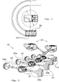
Fig. 1 is a schematic explanatory sketch of a hub reduction gear according to the invention; -
Fig. 2 shows a normal drive mode of the hub reduction gear infig. 1 ; -
Fig. 3 shows a drive mode of the hub reduction gear during pivot turn of the vehicle; -
Fig. 4 shows a schematic plan view of a four wheeled vehicle, performing a pivot turn as well as a curve turn; and -
Fig. 5 shows an example of a drive line for a four wheeled vehicle according to the invention. - In
fig. 1-3 is a schematically showed hub reduction gear for multi shaft, wheel supported vehicles generally denoted with 10. Thehub reduction gear 10 comprises in a known way a planetary gear with acentral sun gear 12 connected thereto and with a thereto belonging drive shaft (not shown), acarrier 14 for a plurality ofplanet gears 16 being in mesh with thesun gear 12, andring gear 18, surrounding theplanet gears 16 and being in mesh internally with these. According to the invention theplanet gear carrier 14 is fixedly connectable to thedriving wheel 20 of the vehicle by means of a first engagable anddisengagable clutch 22 and engagably and disengagably connected to the body-fixedpart 24 of the vehicle by means of a second engagable anddisengagable clutch 26. Further thering gear 18 is likewise fixedly connectable to thedriving wheel 20 of the vehicle by means of a third engagable anddisengagable clutch 28 and engagably and disengagably connected to the body-fixedpart 24 of the vehicle by means of a fourth engagable and disengagable clutch. Theclutches - In
fig. 2 thehub reduction gear 10 is shown in a normal drive mode for driving of the vehicle forward (or backward), wherein theplanet gear carrier 14 is fixedly connected to thedriving wheel 20 via an engagedfirst clutch 22 and disengaged to the body-fixedpart 24 via thesecond clutch 26, at the same time as thethird clutch 28 is disengaged and thefourth clutch 30 is engaged, such that thering gear 18 is held locked to the body-fixedpart 24 and disengaged to thedriving wheel 20. - In order to facilitate a pivot turn of a wheeled vehicle, i.e. a turning of the vehicle about its substantially vertical centre axis, such as schematically shown in the middle of
fig. 4 , thedriving wheels 20 on one side of the vehicle need to be brought to rotate in the opposite direction to thedriving wheels 20 on the other side of the vehicle. This may be achieved, as shown infig. 3 , by reversing the engaging positions of theclutches hub reduction gears 10 on one side of the vehicle in relation to the ones shown infig. 2 . Thus, theclutches clutches planet gear carrier 14 is locked to the body-fixedpart 24 and thering gear 18 is fixedly connected to thering gear 20. - In
fig. 5 adriveline 32 for a heavy, four shaft wheeled vehicle is schematically shown. Thedriveline 32 includes in this case twodriving motors 34 of arbitrary type, e.g. combustion engines of diesel type,conventional differentials 36 withoutput shafts fig. 1-3 ) ofhub reduction gears 10 on left and right side of the vehicle and being mutually connected viacardan shaft sections 40. In order to be able to perform a pivot turn of the vehicle, only thehub reduction gears 10 on one side of the vehicle needs to be designed in accordance with the invention, i.e. with engagable anddisengagable clutches - It is suitable that the driving
wheels 20 on at least the front and rear shafts of the vehicle are controllable in order to improve the manoeuvrability of the vehicle on road and in terrain. In the example infig. 3 and4 the driving wheels on the front shafts are controllable as well as the ones on the rear shaft.
Claims (10)
- Hub reduction gear for a driving wheel (20) of a wheeled vehicle, comprising a planetary gear unit, which has a sun gear (12) connectable to a drive shaft (38a, 38b), a carrier (14) for planet gears (16), which are in mesh with the sun gear (12), and a ring gear (18) surrounding the planet gears (16), being in mesh with the planet gears (16), characterised in that the planet gear carrier (16) and the ring gear (18) are configured to be alternately connected to the driving wheels (20) of the vehicle and being alternately connectable to a body-fixed part (24).
- Hub reduction gear according to claim 1, characterised in that the planet gear carrier (14) is fixedly connectable to the driving wheel (20) of the vehicle by means of a first engagable and disengagable clutch (22) and engagably and disengagably connected to the body-fixed part (24) of the vehicle by means of a second engagable and disengagable clutch (26), while the ring gear (18) is fixedly connectable to the driving wheel (20) of the vehicle by means of a third engagable and disengagable clutch (28) and engagably and disengagably connected to the body-fixed part (24) of the vehicle by means of a fourth engagable and disengagable clutch (30), wherein the first and fourth clutches (22, 30) are arranged to be engaged when the second and third clutches (26, 28) are disengaged and vice versa.
- Hub reduction gear according to claim 1 or 2, characterised by all clutches (22, 26, 28, 30) being constituted by claw clutches.
- Hub reduction gear according to claim 2 or 3, characterised by all clutches (22, 26, 28, 30) being electrically, pneumatically or hydraulically controllable between their engaged and disengaged positions.
- Driveline (32) for a multi shaft wheel supported vehicle with drive on the wheel (20) on several shafts (38a, 38b), comprising at least one driving motor (34), a transmission connected to the driving motor, an output shaft from the transmission, wherein each wheel shaft is co-ordinated to a differential with output left and right drive shaft (38a, 38b) and the differentials (36) being mutually connected by means of cardan shaft section (40), characterised in that each driving vehicle wheel (20) in the driveline (32) comprises a hub reduction gear (10) according to any of the claims 1 - 4, and in that the planet gear carrier (14) and the ring gear (18) of the planetary gear units on at least one side of the vehicle are configured to be alternately connected to the driving wheels (20) of the vehicle and being alternately connectable to a body-fixed part (24).
- Driveline according to claim 5, characterised in that the planet gear carrier (14) is fixedly connectable to the driving wheel (20) of the vehicle by means of a first engagable and disengagable clutch (22) and engagably and disengagably connected to the body-fixed part (24) of the vehicle by means of a second engagable and disengagable clutch (26), while the ring gear (18) is fixedly connectable to the driving wheel (20) of the vehicle by means of a third engagable and disengagable clutch (28) and engagably and disengagably connected to the body-fixed part (24) of the vehicle by means of a fourth engagable and disengagable clutch (30), wherein the first and fourth clutches (22, 30) are arranged to be engaged when the second and third clutches (26, 28) are disengaged and vice versa.
- Driveline according to claim 5 or 6, characterised in that the planet gear carrier (14) and the ring gear (18) of the planetary gear units on both sides of the vehicle are configured to be alternately connected to the driving wheels (20) of the vehicle and being alternately connectable to a body-fixed part (24).
- Driveline according to any of claims 5-7, characterised in that the driving wheels (20) on at least the front and rear shafts are steerable.
- Multi shaft, wheel supported vehicle with drive on the wheels (20) on several shafts, comprising a drive line (32) according to any of claims 5-8.
- Multi shaft, wheel supported vehicle according to claim 9, comprising at least three shafts, wherein at least the wheels (20) on the front and rear shafts are steerable.
Applications Claiming Priority (2)
| Application Number | Priority Date | Filing Date | Title |
|---|---|---|---|
| SE0802192A SE533000C2 (en) | 2008-10-14 | 2008-10-14 | Hub reduction gear for wheeled vehicles and driveline for such vehicle as well as multi-axle wheeled vehicle equipped with such driveline |
| PCT/SE2009/051044 WO2010044722A1 (en) | 2008-10-14 | 2009-09-21 | Hub reduction gear for wheeled vehicle and driveline for such a vehicle and multi-shaft wheeled vehicle with such a driveline |
Publications (3)
| Publication Number | Publication Date |
|---|---|
| EP2344782A1 EP2344782A1 (en) | 2011-07-20 |
| EP2344782A4 EP2344782A4 (en) | 2016-06-15 |
| EP2344782B1 true EP2344782B1 (en) | 2018-11-07 |
Family
ID=42106710
Family Applications (1)
| Application Number | Title | Priority Date | Filing Date |
|---|---|---|---|
| EP09820833.3A Not-in-force EP2344782B1 (en) | 2008-10-14 | 2009-09-21 | Hub reduction gear for wheeled vehicle and driveline for such a vehicle and multi-shaft wheeled vehicle with such a driveline |
Country Status (10)
| Country | Link |
|---|---|
| US (1) | US8950532B2 (en) |
| EP (1) | EP2344782B1 (en) |
| CN (1) | CN102187122B (en) |
| BR (1) | BRPI0920256A2 (en) |
| CA (1) | CA2740144A1 (en) |
| ES (1) | ES2708557T3 (en) |
| SE (1) | SE533000C2 (en) |
| TR (1) | TR201820890T4 (en) |
| WO (1) | WO2010044722A1 (en) |
| ZA (1) | ZA201102739B (en) |
Families Citing this family (6)
| Publication number | Priority date | Publication date | Assignee | Title |
|---|---|---|---|---|
| CN102562955B (en) * | 2010-12-17 | 2016-02-17 | 方盛车桥(柳州)有限公司 | Novel wheel hub reduction mechanism with bevel gears |
| CN204998341U (en) * | 2015-10-13 | 2016-01-27 | 徐继钊 | Wheel edge drive arrangement |
| WO2017114423A1 (en) * | 2015-12-31 | 2017-07-06 | Byd Company Limited | Electric drive axle assembly and vehicle having the electric drive axle assembly |
| EP3847046B1 (en) * | 2018-09-06 | 2022-10-12 | Volvo Construction Equipment AB | Wheel hub arrangement for a driving wheel of a vehicle |
| DE102019207924A1 (en) * | 2019-05-29 | 2020-12-03 | Robert Bosch Gmbh | Gear, especially for a single wheel drive unit |
| CN112440733A (en) * | 2019-08-27 | 2021-03-05 | 比亚迪股份有限公司 | Hub reduction gear, hub power assembly and vehicle |
Family Cites Families (26)
| Publication number | Priority date | Publication date | Assignee | Title |
|---|---|---|---|---|
| US2618175A (en) * | 1946-04-08 | 1952-11-18 | James B Bruce | Automatic fluid brake governed speed regulating transmission |
| US3217565A (en) * | 1964-03-09 | 1965-11-16 | Otto E Dietrich | Reversible tool driving attachment |
| DE1680218A1 (en) * | 1967-06-05 | 1972-06-08 | Ruf Walter Dipl Ing | Swing arm for a motor vehicle, in particular an armored vehicle |
| US4350190A (en) * | 1978-08-17 | 1982-09-21 | Owens-Illinois, Inc. | Self propelled, off road vehicle |
| JPS57104410A (en) | 1980-12-22 | 1982-06-29 | Toyo Umpanki Co Ltd | Driving shaft device |
| JP2671463B2 (en) * | 1988-12-07 | 1997-10-29 | トヨタ自動車株式会社 | Gearbox for automatic transmission |
| WO1992001173A1 (en) * | 1990-07-03 | 1992-01-23 | Zahnradfabrik Friedrichshafen Ag | Range change gearbox for vehicles |
| DE19709588C1 (en) | 1997-03-08 | 1998-10-01 | Zahnradfabrik Friedrichshafen | Drive system for vehicle with independently=driven wheels |
| USRE39179E1 (en) * | 1998-11-03 | 2006-07-11 | Renk Aktiengesellschaft | Electromechanical drive for track-laying vehicles |
| US6354977B1 (en) * | 1999-03-09 | 2002-03-12 | New Venture Gear, Inc. | Transfer case with hydraulic range shift and adaptive clutch control |
| KR100425277B1 (en) * | 2000-08-12 | 2004-03-30 | 한승우 | Wheel transmission |
| WO2002030698A1 (en) | 2000-10-10 | 2002-04-18 | Terex Corporation | Two speed gear box |
| DE10123194A1 (en) * | 2001-05-12 | 2002-11-21 | Voith Turbo Kg | Automatic transmission for lorry or bus is suitable for transverse or fore-and aft engine and transmission installation and has electronic control system |
| EP1258658A3 (en) * | 2001-05-14 | 2009-07-15 | Nissan Motor Company, Limited | Auxiliary Transmission |
| KR100435278B1 (en) | 2001-09-11 | 2004-06-11 | 한승우 | Wheel transmission |
| US6811514B2 (en) | 2002-01-23 | 2004-11-02 | Axletech International Ip Holdings, Llc | Electronic drive unit assembly for heavy duty vehicles |
| US7101307B2 (en) * | 2003-07-14 | 2006-09-05 | Luke W. Clauson | Methods and devices for altering the transmission ratio of a drive system |
| US20050205329A1 (en) * | 2004-02-25 | 2005-09-22 | Shimon Fanger-Vexler | Vehicle and vehicle drive-through suspension arm |
| US7267627B2 (en) * | 2004-05-24 | 2007-09-11 | Magna Powertrain Usa, Inc. | Torque vectoring axle assembly |
| US7410017B2 (en) * | 2004-11-30 | 2008-08-12 | The Timken Company | Electric drive axle |
| EP1944526B1 (en) * | 2005-10-26 | 2012-08-15 | Aisin Aw Co., Ltd. | Hybrid drive device |
| SE529605C2 (en) * | 2006-02-10 | 2007-10-02 | Bae Systems Haegglunds Ab | Differential gear for a multi-axle, wheel-borne motor vehicle, as well as drive transmission containing several such differential gears |
| CN101448665B (en) * | 2006-03-15 | 2012-12-26 | Tm4股份有限公司 | Hybrid transmission for hybrid vehicles |
| JP5204098B2 (en) * | 2006-04-30 | 2013-06-05 | トマクテック・アクティーゼルスカブ | transmission |
| US7845445B2 (en) * | 2007-03-29 | 2010-12-07 | Arvinmeritor Technology, Llc | Electric powertrain system with planetary drive |
| US8137233B2 (en) * | 2008-01-24 | 2012-03-20 | GM Global Technology Operations LLC | Wrap-around driveline with multi-speed transmission |
-
2008
- 2008-10-14 SE SE0802192A patent/SE533000C2/en not_active IP Right Cessation
-
2009
- 2009-09-21 BR BRPI0920256A patent/BRPI0920256A2/en not_active Application Discontinuation
- 2009-09-21 WO PCT/SE2009/051044 patent/WO2010044722A1/en not_active Ceased
- 2009-09-21 EP EP09820833.3A patent/EP2344782B1/en not_active Not-in-force
- 2009-09-21 ES ES09820833T patent/ES2708557T3/en active Active
- 2009-09-21 TR TR2018/20890T patent/TR201820890T4/en unknown
- 2009-09-21 CN CN200980140644.8A patent/CN102187122B/en not_active Expired - Fee Related
- 2009-09-21 US US13/124,086 patent/US8950532B2/en not_active Expired - Fee Related
- 2009-09-21 CA CA2740144A patent/CA2740144A1/en not_active Abandoned
-
2011
- 2011-04-12 ZA ZA2011/02739A patent/ZA201102739B/en unknown
Non-Patent Citations (1)
| Title |
|---|
| None * |
Also Published As
| Publication number | Publication date |
|---|---|
| WO2010044722A1 (en) | 2010-04-22 |
| EP2344782A1 (en) | 2011-07-20 |
| CA2740144A1 (en) | 2010-04-22 |
| BRPI0920256A2 (en) | 2016-01-05 |
| CN102187122A (en) | 2011-09-14 |
| ZA201102739B (en) | 2011-12-28 |
| SE0802192A1 (en) | 2010-04-15 |
| TR201820890T4 (en) | 2019-02-21 |
| US8950532B2 (en) | 2015-02-10 |
| US20110201472A1 (en) | 2011-08-18 |
| ES2708557T3 (en) | 2019-04-10 |
| EP2344782A4 (en) | 2016-06-15 |
| CN102187122B (en) | 2015-04-22 |
| SE533000C2 (en) | 2010-06-08 |
Similar Documents
| Publication | Publication Date | Title |
|---|---|---|
| US9199527B2 (en) | Drive train of a purely electrically all-wheel drivable motor vehicle | |
| US6056660A (en) | Differential gear | |
| US8678968B2 (en) | Drive unit, particularly rear drive unit, for an all-wheel drive of a motor vehicle | |
| US8950532B2 (en) | Hub reduction gear and driveline for a wheeled vehicle and multi-shaft wheeled vehicle | |
| JPS6361210B2 (en) | ||
| JPH0637141B2 (en) | Two-wheel / four-wheel drive switching device | |
| US4357840A (en) | Multi-speed planetary differential | |
| US6554729B2 (en) | Steer-drive for boats and planes | |
| US6478706B1 (en) | Planetary steering differential | |
| US20200317046A1 (en) | A differential | |
| EP1981732B1 (en) | A differential gear for a multi-shaft wheeled motor vehicle, and a drive train comprising several such differential gears | |
| AU2002225934A1 (en) | Steer-drive for vehicles | |
| WO1995024325A1 (en) | Travelling drive device for work vehicle | |
| US20250020197A1 (en) | Electric axle drive for an axle of a motor vehicle, in particular of an automobile, and a motor vehicle, in particular an automobile | |
| JP4116146B2 (en) | Differential device | |
| EP4082814B1 (en) | Power transmission device and automobile including the same | |
| EP4238802B1 (en) | Improved torque distributor system among axles of a heavy vehicle | |
| CN112313429A (en) | Transmission device for a motor vehicle, in particular a motor vehicle | |
| JP4142768B2 (en) | Differential device | |
| CN219172184U (en) | Driving axle and vehicle with same | |
| JP2006029438A (en) | Vehicle drive apparatus and automobile equipped with the same | |
| JP4626747B2 (en) | Torque distribution control device | |
| AU538375B2 (en) | Planetary steering differential | |
| JPH02286941A (en) | Differential device | |
| CN120677324A (en) | Electric drive train for a motor vehicle, in particular a motor vehicle, and motor vehicle |
Legal Events
| Date | Code | Title | Description |
|---|---|---|---|
| PUAI | Public reference made under article 153(3) epc to a published international application that has entered the european phase |
Free format text: ORIGINAL CODE: 0009012 |
|
| 17P | Request for examination filed |
Effective date: 20110509 |
|
| AK | Designated contracting states |
Kind code of ref document: A1 Designated state(s): AT BE BG CH CY CZ DE DK EE ES FI FR GB GR HR HU IE IS IT LI LT LU LV MC MK MT NL NO PL PT RO SE SI SK SM TR |
|
| AX | Request for extension of the european patent |
Extension state: AL BA RS |
|
| DAX | Request for extension of the european patent (deleted) | ||
| RA4 | Supplementary search report drawn up and despatched (corrected) |
Effective date: 20160519 |
|
| RIC1 | Information provided on ipc code assigned before grant |
Ipc: B60K 17/36 20060101ALI20160512BHEP Ipc: B60K 17/02 20060101ALI20160512BHEP Ipc: B60K 17/04 20060101ALI20160512BHEP Ipc: F16H 3/60 20060101AFI20160512BHEP |
|
| GRAP | Despatch of communication of intention to grant a patent |
Free format text: ORIGINAL CODE: EPIDOSNIGR1 |
|
| STAA | Information on the status of an ep patent application or granted ep patent |
Free format text: STATUS: GRANT OF PATENT IS INTENDED |
|
| INTG | Intention to grant announced |
Effective date: 20180606 |
|
| GRAS | Grant fee paid |
Free format text: ORIGINAL CODE: EPIDOSNIGR3 |
|
| GRAA | (expected) grant |
Free format text: ORIGINAL CODE: 0009210 |
|
| STAA | Information on the status of an ep patent application or granted ep patent |
Free format text: STATUS: THE PATENT HAS BEEN GRANTED |
|
| AK | Designated contracting states |
Kind code of ref document: B1 Designated state(s): AT BE BG CH CY CZ DE DK EE ES FI FR GB GR HR HU IE IS IT LI LT LU LV MC MK MT NL NO PL PT RO SE SI SK SM TR |
|
| REG | Reference to a national code |
Ref country code: GB Ref legal event code: FG4D |
|
| REG | Reference to a national code |
Ref country code: CH Ref legal event code: EP Ref country code: AT Ref legal event code: REF Ref document number: 1062422 Country of ref document: AT Kind code of ref document: T Effective date: 20181115 |
|
| REG | Reference to a national code |
Ref country code: IE Ref legal event code: FG4D |
|
| REG | Reference to a national code |
Ref country code: DE Ref legal event code: R096 Ref document number: 602009055547 Country of ref document: DE |
|
| REG | Reference to a national code |
Ref country code: CH Ref legal event code: NV Representative=s name: ISLER AND PEDRAZZINI AG, CH |
|
| REG | Reference to a national code |
Ref country code: NL Ref legal event code: FP |
|
| REG | Reference to a national code |
Ref country code: LT Ref legal event code: MG4D |
|
| REG | Reference to a national code |
Ref country code: ES Ref legal event code: FG2A Ref document number: 2708557 Country of ref document: ES Kind code of ref document: T3 Effective date: 20190410 |
|
| PG25 | Lapsed in a contracting state [announced via postgrant information from national office to epo] |
Ref country code: LV Free format text: LAPSE BECAUSE OF FAILURE TO SUBMIT A TRANSLATION OF THE DESCRIPTION OR TO PAY THE FEE WITHIN THE PRESCRIBED TIME-LIMIT Effective date: 20181107 Ref country code: LT Free format text: LAPSE BECAUSE OF FAILURE TO SUBMIT A TRANSLATION OF THE DESCRIPTION OR TO PAY THE FEE WITHIN THE PRESCRIBED TIME-LIMIT Effective date: 20181107 Ref country code: IS Free format text: LAPSE BECAUSE OF FAILURE TO SUBMIT A TRANSLATION OF THE DESCRIPTION OR TO PAY THE FEE WITHIN THE PRESCRIBED TIME-LIMIT Effective date: 20190307 Ref country code: NO Free format text: LAPSE BECAUSE OF FAILURE TO SUBMIT A TRANSLATION OF THE DESCRIPTION OR TO PAY THE FEE WITHIN THE PRESCRIBED TIME-LIMIT Effective date: 20190207 Ref country code: HR Free format text: LAPSE BECAUSE OF FAILURE TO SUBMIT A TRANSLATION OF THE DESCRIPTION OR TO PAY THE FEE WITHIN THE PRESCRIBED TIME-LIMIT Effective date: 20181107 Ref country code: BG Free format text: LAPSE BECAUSE OF FAILURE TO SUBMIT A TRANSLATION OF THE DESCRIPTION OR TO PAY THE FEE WITHIN THE PRESCRIBED TIME-LIMIT Effective date: 20190207 |
|
| PG25 | Lapsed in a contracting state [announced via postgrant information from national office to epo] |
Ref country code: SE Free format text: LAPSE BECAUSE OF FAILURE TO SUBMIT A TRANSLATION OF THE DESCRIPTION OR TO PAY THE FEE WITHIN THE PRESCRIBED TIME-LIMIT Effective date: 20181107 Ref country code: PT Free format text: LAPSE BECAUSE OF FAILURE TO SUBMIT A TRANSLATION OF THE DESCRIPTION OR TO PAY THE FEE WITHIN THE PRESCRIBED TIME-LIMIT Effective date: 20190307 Ref country code: GR Free format text: LAPSE BECAUSE OF FAILURE TO SUBMIT A TRANSLATION OF THE DESCRIPTION OR TO PAY THE FEE WITHIN THE PRESCRIBED TIME-LIMIT Effective date: 20190208 |
|
| PG25 | Lapsed in a contracting state [announced via postgrant information from national office to epo] |
Ref country code: CZ Free format text: LAPSE BECAUSE OF FAILURE TO SUBMIT A TRANSLATION OF THE DESCRIPTION OR TO PAY THE FEE WITHIN THE PRESCRIBED TIME-LIMIT Effective date: 20181107 Ref country code: PL Free format text: LAPSE BECAUSE OF FAILURE TO SUBMIT A TRANSLATION OF THE DESCRIPTION OR TO PAY THE FEE WITHIN THE PRESCRIBED TIME-LIMIT Effective date: 20181107 Ref country code: DK Free format text: LAPSE BECAUSE OF FAILURE TO SUBMIT A TRANSLATION OF THE DESCRIPTION OR TO PAY THE FEE WITHIN THE PRESCRIBED TIME-LIMIT Effective date: 20181107 |
|
| REG | Reference to a national code |
Ref country code: DE Ref legal event code: R097 Ref document number: 602009055547 Country of ref document: DE |
|
| PG25 | Lapsed in a contracting state [announced via postgrant information from national office to epo] |
Ref country code: SK Free format text: LAPSE BECAUSE OF FAILURE TO SUBMIT A TRANSLATION OF THE DESCRIPTION OR TO PAY THE FEE WITHIN THE PRESCRIBED TIME-LIMIT Effective date: 20181107 Ref country code: RO Free format text: LAPSE BECAUSE OF FAILURE TO SUBMIT A TRANSLATION OF THE DESCRIPTION OR TO PAY THE FEE WITHIN THE PRESCRIBED TIME-LIMIT Effective date: 20181107 Ref country code: EE Free format text: LAPSE BECAUSE OF FAILURE TO SUBMIT A TRANSLATION OF THE DESCRIPTION OR TO PAY THE FEE WITHIN THE PRESCRIBED TIME-LIMIT Effective date: 20181107 Ref country code: SM Free format text: LAPSE BECAUSE OF FAILURE TO SUBMIT A TRANSLATION OF THE DESCRIPTION OR TO PAY THE FEE WITHIN THE PRESCRIBED TIME-LIMIT Effective date: 20181107 |
|
| PLBE | No opposition filed within time limit |
Free format text: ORIGINAL CODE: 0009261 |
|
| STAA | Information on the status of an ep patent application or granted ep patent |
Free format text: STATUS: NO OPPOSITION FILED WITHIN TIME LIMIT |
|
| 26N | No opposition filed |
Effective date: 20190808 |
|
| PG25 | Lapsed in a contracting state [announced via postgrant information from national office to epo] |
Ref country code: SI Free format text: LAPSE BECAUSE OF FAILURE TO SUBMIT A TRANSLATION OF THE DESCRIPTION OR TO PAY THE FEE WITHIN THE PRESCRIBED TIME-LIMIT Effective date: 20181107 |
|
| PGFP | Annual fee paid to national office [announced via postgrant information from national office to epo] |
Ref country code: FI Payment date: 20190920 Year of fee payment: 11 Ref country code: FR Payment date: 20190925 Year of fee payment: 11 Ref country code: NL Payment date: 20190926 Year of fee payment: 11 Ref country code: IT Payment date: 20190923 Year of fee payment: 11 Ref country code: TR Payment date: 20190919 Year of fee payment: 11 |
|
| PGFP | Annual fee paid to national office [announced via postgrant information from national office to epo] |
Ref country code: AT Payment date: 20190920 Year of fee payment: 11 Ref country code: GB Payment date: 20190930 Year of fee payment: 11 |
|
| PGFP | Annual fee paid to national office [announced via postgrant information from national office to epo] |
Ref country code: CH Payment date: 20190925 Year of fee payment: 11 Ref country code: DE Payment date: 20190930 Year of fee payment: 11 |
|
| PGFP | Annual fee paid to national office [announced via postgrant information from national office to epo] |
Ref country code: ES Payment date: 20191021 Year of fee payment: 11 |
|
| PG25 | Lapsed in a contracting state [announced via postgrant information from national office to epo] |
Ref country code: MC Free format text: LAPSE BECAUSE OF FAILURE TO SUBMIT A TRANSLATION OF THE DESCRIPTION OR TO PAY THE FEE WITHIN THE PRESCRIBED TIME-LIMIT Effective date: 20181107 |
|
| PG25 | Lapsed in a contracting state [announced via postgrant information from national office to epo] |
Ref country code: LU Free format text: LAPSE BECAUSE OF NON-PAYMENT OF DUE FEES Effective date: 20190921 Ref country code: IE Free format text: LAPSE BECAUSE OF NON-PAYMENT OF DUE FEES Effective date: 20190921 |
|
| REG | Reference to a national code |
Ref country code: BE Ref legal event code: MM Effective date: 20190930 |
|
| PG25 | Lapsed in a contracting state [announced via postgrant information from national office to epo] |
Ref country code: BE Free format text: LAPSE BECAUSE OF NON-PAYMENT OF DUE FEES Effective date: 20190930 |
|
| REG | Reference to a national code |
Ref country code: AT Ref legal event code: UEP Ref document number: 1062422 Country of ref document: AT Kind code of ref document: T Effective date: 20181107 |
|
| REG | Reference to a national code |
Ref country code: DE Ref legal event code: R119 Ref document number: 602009055547 Country of ref document: DE |
|
| REG | Reference to a national code |
Ref country code: FI Ref legal event code: MAE |
|
| PG25 | Lapsed in a contracting state [announced via postgrant information from national office to epo] |
Ref country code: FI Free format text: LAPSE BECAUSE OF NON-PAYMENT OF DUE FEES Effective date: 20200921 |
|
| REG | Reference to a national code |
Ref country code: CH Ref legal event code: PL |
|
| REG | Reference to a national code |
Ref country code: NL Ref legal event code: MM Effective date: 20201001 |
|
| REG | Reference to a national code |
Ref country code: AT Ref legal event code: MM01 Ref document number: 1062422 Country of ref document: AT Kind code of ref document: T Effective date: 20200921 |
|
| GBPC | Gb: european patent ceased through non-payment of renewal fee |
Effective date: 20200921 |
|
| PG25 | Lapsed in a contracting state [announced via postgrant information from national office to epo] |
Ref country code: CY Free format text: LAPSE BECAUSE OF FAILURE TO SUBMIT A TRANSLATION OF THE DESCRIPTION OR TO PAY THE FEE WITHIN THE PRESCRIBED TIME-LIMIT Effective date: 20181107 |
|
| PG25 | Lapsed in a contracting state [announced via postgrant information from national office to epo] |
Ref country code: NL Free format text: LAPSE BECAUSE OF NON-PAYMENT OF DUE FEES Effective date: 20201001 |
|
| PG25 | Lapsed in a contracting state [announced via postgrant information from national office to epo] |
Ref country code: FR Free format text: LAPSE BECAUSE OF NON-PAYMENT OF DUE FEES Effective date: 20200930 Ref country code: DE Free format text: LAPSE BECAUSE OF NON-PAYMENT OF DUE FEES Effective date: 20210401 Ref country code: MT Free format text: LAPSE BECAUSE OF FAILURE TO SUBMIT A TRANSLATION OF THE DESCRIPTION OR TO PAY THE FEE WITHIN THE PRESCRIBED TIME-LIMIT Effective date: 20181107 Ref country code: HU Free format text: LAPSE BECAUSE OF FAILURE TO SUBMIT A TRANSLATION OF THE DESCRIPTION OR TO PAY THE FEE WITHIN THE PRESCRIBED TIME-LIMIT; INVALID AB INITIO Effective date: 20090921 |
|
| PG25 | Lapsed in a contracting state [announced via postgrant information from national office to epo] |
Ref country code: AT Free format text: LAPSE BECAUSE OF NON-PAYMENT OF DUE FEES Effective date: 20200921 Ref country code: CH Free format text: LAPSE BECAUSE OF NON-PAYMENT OF DUE FEES Effective date: 20200930 Ref country code: LI Free format text: LAPSE BECAUSE OF NON-PAYMENT OF DUE FEES Effective date: 20200930 Ref country code: GB Free format text: LAPSE BECAUSE OF NON-PAYMENT OF DUE FEES Effective date: 20200921 |
|
| PG25 | Lapsed in a contracting state [announced via postgrant information from national office to epo] |
Ref country code: IT Free format text: LAPSE BECAUSE OF NON-PAYMENT OF DUE FEES Effective date: 20200921 |
|
| REG | Reference to a national code |
Ref country code: ES Ref legal event code: FD2A Effective date: 20220118 |
|
| PG25 | Lapsed in a contracting state [announced via postgrant information from national office to epo] |
Ref country code: ES Free format text: LAPSE BECAUSE OF NON-PAYMENT OF DUE FEES Effective date: 20200922 |
|
| PG25 | Lapsed in a contracting state [announced via postgrant information from national office to epo] |
Ref country code: TR Free format text: LAPSE BECAUSE OF NON-PAYMENT OF DUE FEES Effective date: 20200921 Ref country code: MK Free format text: LAPSE BECAUSE OF FAILURE TO SUBMIT A TRANSLATION OF THE DESCRIPTION OR TO PAY THE FEE WITHIN THE PRESCRIBED TIME-LIMIT Effective date: 20181107 |