EP2343769A1 - Apparatus for heating and cooling a battery and sub-assembly of vehicle drive batteries - Google Patents
Apparatus for heating and cooling a battery and sub-assembly of vehicle drive batteries Download PDFInfo
- Publication number
- EP2343769A1 EP2343769A1 EP20100195759 EP10195759A EP2343769A1 EP 2343769 A1 EP2343769 A1 EP 2343769A1 EP 20100195759 EP20100195759 EP 20100195759 EP 10195759 A EP10195759 A EP 10195759A EP 2343769 A1 EP2343769 A1 EP 2343769A1
- Authority
- EP
- European Patent Office
- Prior art keywords
- heat
- battery
- heating element
- transfer component
- electrical heating
- Prior art date
- Legal status (The legal status is an assumption and is not a legal conclusion. Google has not performed a legal analysis and makes no representation as to the accuracy of the status listed.)
- Granted
Links
Images


Classifications
-
- H—ELECTRICITY
- H01—ELECTRIC ELEMENTS
- H01M—PROCESSES OR MEANS, e.g. BATTERIES, FOR THE DIRECT CONVERSION OF CHEMICAL ENERGY INTO ELECTRICAL ENERGY
- H01M10/00—Secondary cells; Manufacture thereof
- H01M10/60—Heating or cooling; Temperature control
- H01M10/61—Types of temperature control
- H01M10/613—Cooling or keeping cold
-
- F—MECHANICAL ENGINEERING; LIGHTING; HEATING; WEAPONS; BLASTING
- F28—HEAT EXCHANGE IN GENERAL
- F28F—DETAILS OF HEAT-EXCHANGE AND HEAT-TRANSFER APPARATUS, OF GENERAL APPLICATION
- F28F1/00—Tubular elements; Assemblies of tubular elements
- F28F1/10—Tubular elements and assemblies thereof with means for increasing heat-transfer area, e.g. with fins, with projections, with recesses
- F28F1/12—Tubular elements and assemblies thereof with means for increasing heat-transfer area, e.g. with fins, with projections, with recesses the means being only outside the tubular element
- F28F1/14—Tubular elements and assemblies thereof with means for increasing heat-transfer area, e.g. with fins, with projections, with recesses the means being only outside the tubular element and extending longitudinally
- F28F1/20—Tubular elements and assemblies thereof with means for increasing heat-transfer area, e.g. with fins, with projections, with recesses the means being only outside the tubular element and extending longitudinally the means being attachable to the element
-
- F—MECHANICAL ENGINEERING; LIGHTING; HEATING; WEAPONS; BLASTING
- F28—HEAT EXCHANGE IN GENERAL
- F28F—DETAILS OF HEAT-EXCHANGE AND HEAT-TRANSFER APPARATUS, OF GENERAL APPLICATION
- F28F1/00—Tubular elements; Assemblies of tubular elements
- F28F1/10—Tubular elements and assemblies thereof with means for increasing heat-transfer area, e.g. with fins, with projections, with recesses
- F28F1/12—Tubular elements and assemblies thereof with means for increasing heat-transfer area, e.g. with fins, with projections, with recesses the means being only outside the tubular element
- F28F1/14—Tubular elements and assemblies thereof with means for increasing heat-transfer area, e.g. with fins, with projections, with recesses the means being only outside the tubular element and extending longitudinally
- F28F1/22—Tubular elements and assemblies thereof with means for increasing heat-transfer area, e.g. with fins, with projections, with recesses the means being only outside the tubular element and extending longitudinally the means having portions engaging further tubular elements
-
- H—ELECTRICITY
- H01—ELECTRIC ELEMENTS
- H01M—PROCESSES OR MEANS, e.g. BATTERIES, FOR THE DIRECT CONVERSION OF CHEMICAL ENERGY INTO ELECTRICAL ENERGY
- H01M10/00—Secondary cells; Manufacture thereof
- H01M10/60—Heating or cooling; Temperature control
- H01M10/61—Types of temperature control
- H01M10/615—Heating or keeping warm
-
- H—ELECTRICITY
- H01—ELECTRIC ELEMENTS
- H01M—PROCESSES OR MEANS, e.g. BATTERIES, FOR THE DIRECT CONVERSION OF CHEMICAL ENERGY INTO ELECTRICAL ENERGY
- H01M10/00—Secondary cells; Manufacture thereof
- H01M10/60—Heating or cooling; Temperature control
- H01M10/62—Heating or cooling; Temperature control specially adapted for specific applications
- H01M10/625—Vehicles
-
- H—ELECTRICITY
- H01—ELECTRIC ELEMENTS
- H01M—PROCESSES OR MEANS, e.g. BATTERIES, FOR THE DIRECT CONVERSION OF CHEMICAL ENERGY INTO ELECTRICAL ENERGY
- H01M10/00—Secondary cells; Manufacture thereof
- H01M10/60—Heating or cooling; Temperature control
- H01M10/64—Heating or cooling; Temperature control characterised by the shape of the cells
- H01M10/647—Prismatic or flat cells, e.g. pouch cells
-
- H—ELECTRICITY
- H01—ELECTRIC ELEMENTS
- H01M—PROCESSES OR MEANS, e.g. BATTERIES, FOR THE DIRECT CONVERSION OF CHEMICAL ENERGY INTO ELECTRICAL ENERGY
- H01M10/00—Secondary cells; Manufacture thereof
- H01M10/60—Heating or cooling; Temperature control
- H01M10/65—Means for temperature control structurally associated with the cells
- H01M10/655—Solid structures for heat exchange or heat conduction
- H01M10/6554—Rods or plates
-
- H—ELECTRICITY
- H01—ELECTRIC ELEMENTS
- H01M—PROCESSES OR MEANS, e.g. BATTERIES, FOR THE DIRECT CONVERSION OF CHEMICAL ENERGY INTO ELECTRICAL ENERGY
- H01M10/00—Secondary cells; Manufacture thereof
- H01M10/60—Heating or cooling; Temperature control
- H01M10/65—Means for temperature control structurally associated with the cells
- H01M10/655—Solid structures for heat exchange or heat conduction
- H01M10/6556—Solid parts with flow channel passages or pipes for heat exchange
-
- H—ELECTRICITY
- H01—ELECTRIC ELEMENTS
- H01M—PROCESSES OR MEANS, e.g. BATTERIES, FOR THE DIRECT CONVERSION OF CHEMICAL ENERGY INTO ELECTRICAL ENERGY
- H01M10/00—Secondary cells; Manufacture thereof
- H01M10/60—Heating or cooling; Temperature control
- H01M10/65—Means for temperature control structurally associated with the cells
- H01M10/656—Means for temperature control structurally associated with the cells characterised by the type of heat-exchange fluid
- H01M10/6567—Liquids
-
- H—ELECTRICITY
- H01—ELECTRIC ELEMENTS
- H01M—PROCESSES OR MEANS, e.g. BATTERIES, FOR THE DIRECT CONVERSION OF CHEMICAL ENERGY INTO ELECTRICAL ENERGY
- H01M10/00—Secondary cells; Manufacture thereof
- H01M10/60—Heating or cooling; Temperature control
- H01M10/65—Means for temperature control structurally associated with the cells
- H01M10/657—Means for temperature control structurally associated with the cells by electric or electromagnetic means
- H01M10/6571—Resistive heaters
-
- Y—GENERAL TAGGING OF NEW TECHNOLOGICAL DEVELOPMENTS; GENERAL TAGGING OF CROSS-SECTIONAL TECHNOLOGIES SPANNING OVER SEVERAL SECTIONS OF THE IPC; TECHNICAL SUBJECTS COVERED BY FORMER USPC CROSS-REFERENCE ART COLLECTIONS [XRACs] AND DIGESTS
- Y02—TECHNOLOGIES OR APPLICATIONS FOR MITIGATION OR ADAPTATION AGAINST CLIMATE CHANGE
- Y02E—REDUCTION OF GREENHOUSE GAS [GHG] EMISSIONS, RELATED TO ENERGY GENERATION, TRANSMISSION OR DISTRIBUTION
- Y02E60/00—Enabling technologies; Technologies with a potential or indirect contribution to GHG emissions mitigation
- Y02E60/10—Energy storage using batteries
Definitions
- the invention relates to an apparatus for heating and cooling a battery, preferably a vehicle drive battery with a plurality of battery cells, as well as with a sub-assembly of vehicle drive batteries with a vehicle drive battery and an apparatus for heating and cooling the battery.
- Vehicle drive batteries for purely electric, fuel-cell or hybrid vehicles are at the centre of the development of alternatively driven vehicles.
- the service life of the battery depends to a considerable degree upon the temperature stressing of the battery cells during the charging and discharging procedure. This applies in particular to lithium-ion batteries and NiMH batteries.
- In order to retain the capacity of the battery it is necessary to prevent the battery cells from being heated or heating themselves above their maximum temperature of from 45°C to 60°C.
- cooling apparatus for vehicle drive batteries are known in which the vehicle drive battery is cooled by way of a coolant circuit.
- a vehicle drive battery in the vehicle is subjected to a wide range of ambient temperatures, for example caused by the seasons, in the case of cold ambient temperatures in particular during winter the battery may be operated at cold temperatures.
- the voltage and capacity of the battery are significantly reduced as compared with higher temperatures.
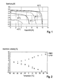
- the maximum permissible charging and discharging capacity at different temperatures for lithium-ion batteries and NiMH batteries is indicated in figure 2 .
- the maximum permissible capacity becomes smaller as temperatures drop, in which case for example a charging procedure or an acceleration procedure of the vehicle is not possible at temperatures below 0°C under normal driving conditions.
- the object of the invention is to provide an apparatus for heating and cooling a battery, which is designed in a compact manner and with low weight, as well as a sub-assembly of vehicle drive batteries which is characterized by a long service capacity on account of its good battery cooling and heating.
- an apparatus for heating and cooling a battery, at least one vehicle drive battery with a plurality of battery cells.
- the apparatus has a coolant circuit which comprises at least one coolant line, at least one electrical heating element and at least one common heat-transfer component for the heat transfer between the battery and the coolant line and the electrical heating element.
- the apparatus can heat or cool the battery by way of the at least one common heat-transfer component, depending upon whether the electrical heating element or the coolant circuit is active. Since the coolant circuit and the electrical heating element can be operated independently of each other, a rapid and precise setting of the cooling capacity or heating capacity is possible and, in particular, a rapid change between the heating function and the cooling function of the apparatus.
- the heat-transfer component is provided for the heat transfer both in the cooling function and in the heating function of the apparatus, the heat-transfer component can be coupled to the battery in an optimally thermally conductive manner.
- the apparatus thus permits a good performance both when cooling and when heating the battery, whilst the apparatus itself can be made compact and with a small structural space and a low weight.
- the coolant line and/or the heating element pre-stressed against it.
- the pre-stressing can be carried out by a resilient pressing force of the coolant line or the heating element or the heat-transfer component. As the coolant line and/or the heating element rest pre-stressed against the heat-transfer component, thermally insulating air gaps between the coolant line and the heat-transfer component and between the heating element and the heat-transfer component are prevented.
- the at least one common heat-transfer component can be connected to the at least one electrical heating element and/or at least one coolant line in a positively or non-positively locking manner.
- a thermally conductive paste can be provided between the heat-transfer component and the electrical heating element.
- a plurality of heat-transfer components in particular those which are associated with a common coolant line, have a common electrical heating element.
- the number of the heating elements required can be reduced in the case of an apparatus with a plurality of heat-transfer components, as a result of which in particular the electrical connection of the heating elements is simplified. If a plurality of heat-transfer components are associated in each case with one common coolant line and one common electrical heating element, then the control of the heating and cooling apparatus is simplified.
- the electrical heating element is embedded in a tubular jacket, preferably of stainless steel.
- An electrical heating element of this type has a high mechanical loading capacity.
- the apparatus is constructed in the form of a cooling base which is designed in such a way that it rests flat against a flat side of the battery and which has a holding means for the at least one coolant line and the at least one electrical heating element.
- a design of the apparatus in the form of a cooling base permits a highly compact design of the apparatus and is suitable, in particular, for novel battery cells in which a cooling is possible by way of only one flat side, for example the lower end wall.
- the cooling base prefferably be made resilient towards the flat side of the battery. In this way the formation of thermally insulating air gaps between the cooling base and the flat side of the battery is prevented.
- the heat-transfer component can be designed in the form of an extruded section or profile.
- the production by extrusion permits a simple production of the heat-transfer component and a polygonal geometry of the profile.
- the heat-transfer component can have two thermal conduction ribs on the side facing away from the battery, which are in thermally conductive contact with the electrical heating element, the distance between the thermal conduction ribs being selected in such a way that a pressing contact is preferably formed between the thermal conduction ribs and the electrical heating element.
- Thermal conduction ribs of this type permit a good thermally conductive contact between the heat-transfer component and the heating element.
- the pressing contact between the thermal conduction ribs and the heating element ensure a lasting thermally conductive contact.
- the thermal conduction ribs prefferably be shaped round at least in part in order to permit a fastening of the heating element with positive locking.
- the connection with positive locking improves the fastening of the heating elements on the heat-transfer component, and the thermally conductive contact region between the heating element and the thermal conduction ribs is increased.
- the electrical heating element extends for example in a U shape, in which case in particular the two arms of the U-shaped heating element are associated with different heat-transfer components in each case.
- the heat-transfer component it is possible for the heat-transfer component to engage around the electrical heating element locally. In this way the thermally conductive contact area between the heat-transfer component and the electrical heating element is increased.
- the heat-transfer component is a contact plate.
- the cooling base and/or the contact plate should be a pre-fabricated, self-supporting unit.
- the heat-transfer component is designed in the form of a resilient part and, in the state not fastened to the battery, convex towards the outside on the outer side thereof facing the battery. If a heat-transfer component of this type is pressed with a specified force against a flat side of the battery, then the outer side of the heat-transfer component facing the battery is pre-stressed in a resilient manner flat against the flat side of the battery, as a result of which thermally insulating air gaps between the heat-transfer component and the battery are prevented.
- the invention also relates, as already indicated in the introduction, to a sub-assembly of vehicle drive batteries, with a vehicle drive battery which comprises a plurality of cylindrical battery cells arranged adjacent to one another and with an external face, an upper end wall and a lower end wall, the battery having a flat side, and an apparatus according to the invention for heating and cooling the vehicle drive battery.
- the apparatus rests with the at least one heat-transfer component against the flat side of the battery.
- a plurality of battery cells can be combined to form a pre-fabricated unit in the form of a group of battery cells.
- the battery as a whole can optionally be formed from a plurality of battery cell groups.
- one heat-transfer component it is preferable for only one heat-transfer component to extend directly on the underside of one battery cell or one battery cell group in each case, one battery cell group being a pre-fabricated unit formed from a plurality of battery cells, in which case a coolant supply, a coolant return and an electrical heating element extend along below each battery cell group, so that all the battery cells of a battery cell group are cooled to substantially the same temperature.
- the apparatus should, in particular, be positioned on the side of the battery facing away from the electrical terminals of the battery. If the upper end wall is the side on which the two poles of the battery are present, the lower end wall should then be the cooled side of the battery.
- the heat-transfer component can be fastened to a housing of the battery and can be pressed by the fastening against a flat side of the battery.
- the heat-transfer component presses resiliently against the flat side of the battery, a base plate of the battery or directly against the battery cells.
- a base plate may be necessary on mechanical grounds just when a sub-assembly is formed, so that the base plate is situated between the batteries and the heat-transfer component or components.
- the base plate should of course consist of highly thermally conductive material.
- the apparatus has provided under it a pressing plate which is preferably fastened to the battery and by which the apparatus is compressed and resiliently deformed between the battery and the pressing plate by way of a sort of sandwich design as it were.
- Vehicle drive batteries are used as energy stores for driving electric motors, for example in electric or hybrid vehicles.
- a vehicle drive battery comprises a plurality of battery cells which are coupled to one another electrically.
- a plurality of battery cells can be arranged in a group of battery cells, in which case a plurality of groups of battery cells together form the vehicle drive battery.
- the battery cells 12 are made cuboid and have an external face as well as an upper and lower end wall.
- the battery cells 12 are connected to one another electrically on the top side of the battery cell group 10 and have a common electrical terminal 16.
- the underside of the battery cell group 10 is a flat side 18 which is made thermally conductive and by way of which a cooling or heating of all the battery cells 12 of the battery cell group 10 by the lower end walls of the cells is possible.
- battery cell groups 10 or individual battery cells 12 may be provided, for example those in which flat sides of the battery cells 12, i.e. for example the lower end walls thereof, are themselves made thermally conductive for the individual cooling of the battery cell 12.
- An apparatus 20 for heating and cooling the battery cell group 10 of the vehicle drive battery is shown in a diagrammatic sectional view in figure 4 .
- the apparatus 20 is designed in the form of a cooling base 22 which can rest flat against the flat side 18 of the battery cell group 10.
- the cooling base 22 comprises a heat-transfer component 24 which is designed in the form of a contact plate and which has an extruded profile of constant cross-section formed along an axis A extending parallel to the flat side 18 of the battery cell group 10.
- the heat-transfer component 24 consists of a material with a high degree of thermal conductivity, for example aluminium or copper, aluminium being preferred on account of its low weight.
- the heat-transfer component 24 comprises a contact top side 26 with which the heat-transfer component 24 rests against the flat side 18 of the battery.
- thermal conduction ribs 30 are provided which form holding means for coolant lines 32 and an electrical heating element 34.
- the thermal conduction ribs 30 are designed in such a way that a good heat transfer between the coolant line 32 and the heat-transfer component 24 and between the electrical heating element 34 and the heat-transfer component 24 is possible.
- the heat-transfer component 24 has an edge profile 36 on the left-hand and right-hand edge of the heat-transfer component 24.
- the two edge profiles 36 reinforce the mechanical structure of the heat-transfer component 24 on the one hand and are made complementary to each other in each case on the other hand, so that similar adjacent heat-transfer components 24 engage in one another with their edge profiles 36 in a positively locking manner.
- Parts of a second heat-transfer component 24 of this type are shown on the right-hand edge of figure 4 .
- the two contact top sides 26 are joined to form a large common contact surface in an aligned manner.
- a large common contact surface is provided, whereas the individual heat-transfer components 24 are relatively small and can thus be produced more simply by extrusion than correspondingly larger heat-transfer components.
- a plurality of small heat-transfer components 24 can adapt more easily to the flat side 18 which is never completely plane.
- a thermal conduction between adjacent heat-transfer components 24 is possible by way of the mutually adjacent edge profiles 36 of the heat-transfer components 24, as a result of which an average temperature and an average cooling or cooling capacity is produced between adjacent heat-transfer components 24.
- thermally conductive paste In order to improve the heat transfer between the coolant lines 32, the electrical heating element 34 and the respective thermal conduction ribs 30, or between adjacent heat-transfer components 24 which abut against one another by way of their edge profiles 36 in a positively locking manner, it is possible for a thermally conductive paste to be provided between the corresponding components.
- the heat-transfer components 24 are connected to the flat side 18 of the battery cell group 10 by way of fastening apparatus 38.
- the fastening apparatus 38 are bolt fastenings with which the heat-transfer components 24 are fastened directly to the flat side 18 of the battery cell group 10.
- a thermal insulation component 40 which is connected to the heat-transfer component 24 in a positively locking manner, is provided on the side of the heat-transfer components 24 opposite the battery cell group 10. To this end the thermal insulation component 40 engages in the edge profiles 36 of the heat-transfer component 24. Recesses are provided in the thermal insulation component 40 for the reinforcement ribs 28, coolant lines 32, the electrical heating element 34 and the thermal conduction ribs 30, as well as the bolts of the fastening apparatus 38. The thermal insulation component 40 can also be fastened in a different manner to the heat-transfer component 24, for example by way of the fastening apparatus 38.
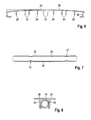
- Figure 5 shows a sub-assembly 100 of vehicle drive batteries which is formed from a battery cell group 10 with a flat side 18 and an apparatus 20 for heating and cooling the vehicle drive battery.
- the apparatus 20 comprises two heat-transfer components 24 which engage in each other in a positively locking manner and which are designed in a manner similar to the heat-transfer component 24 shown in figure 4 .
- FIG. 6 shows the heat-transfer component 24 without further components of the apparatus 20.
- the heat-transfer component 24 is made resilient and in the state not fastened to the flat side 18 of the battery cell group 10 it extends in a convex manner with respect to the flat side 18 of the battery, in which case it preferably has a constant thickness.
- the contact top side 26 extends in a curved manner, the middle region of the heat-transfer component 24 being in particular up to 5 mm higher than the lateral edge of the contact top side 26.
- the heat-transfer component 24 shaped in this way (as shown in figure 5 ) is bolted onto the flat side 18 of the battery cell group 10 by way of the fastening apparatus 38, then the heat-transfer component 24 will rest substantially flat against the flat side 18 of the battery cell group 10 and will be resiliently pre-stressed. In this way, air gaps between the heat-transfer component 24 and the flat side 18 of the battery cell group 10 are prevented.
- the coolant lines 32 are designed in the form of separate tubes, the thermal conduction ribs 30 forming a holding means for the coolant lines 32.
- Figure 5 shows an electrical heating element 34 which is surrounded on both sides by the thermal conduction ribs 30 of the heat-transfer component 24.
- the distance between the thermal conduction ribs 30 is selected in such a way that a pressing contact is formed between the thermal conduction ribs 30 and the electrical heating element 34.
- the electrical heating element 34 is connected to the heat-transfer component 24 by way of the pressing contact in a non-positively locking manner, whilst at the same time a heat transfer is made possible by way of the pressing contact.
- two fastening points 42 are provided, at which the thermal conduction ribs 30 are shaped round in the direction of the electrical heating element 34 in order to permit a connection with positive locking between the electrical heating element 34 and the heat-transfer component 24 at these fastening points 42.
- Figure 6 is a sectional view of a fastening point 42 at which the thermal conduction ribs 30 are curved on both sides in the direction of the electrical heating element 34. It is also possible for only one of the thermal conduction ribs 30 to be curved in the direction of the electrical heating element 34 or for the thermal conduction ribs 30 to be curved along their entire length in the direction of the electrical heating element 34.
- the coolant lines 32 are fastened to the thermal conduction ribs 30 associated with them, in a manner similar to the electrical heating element 34.
- the heating element 34 can be designed in different ways.
- the electrical heating element 34 is a heating coil which is wound cylindrically and which is embedded in a thermally conductive and electrically insulating manner in a tubular jacket of stainless steel.
- the heating element 34 thus has a high degree of mechanical stability.
- Figure 9 shows a second embodiment of the apparatus 20 for heating and cooling, in which case four heat-transfer components 24 are provided.
- Figure 10 shows the same apparatus 20 in an exploded view.
- the fastening rails 44 form the fastening apparatus 38 for fastening the heat-transfer components 24 to the flat side 18 of the battery cell group 10.
- the fastening rails 44 in each case comprise extensions 46 by which they are connected to the edge profile 36 of the heat-transfer component 24 in a positively locking manner (cf. figure 11 ).
- one U-shaped electrical heating element 34 is provided for two adjacent heat-transfer components 24 in each case.
- One arm of the U-shaped heating element 34 is associated in each case with one heat-transfer component 24, the two heat-transfer components 24 which are associated with a U-shaped heating element 34 being situated adjacent to each other.
- the two arms of the U-shaped heating element 34 can be connected to each other in a rigid or flexible manner, for example by way of a cable.
- a coolant duct system 48 is provided which has four coolant lines 32 which are connected in parallel and which are connected to one another by way of a coolant distributor 50 and a common collecting line 52.
- the coolant circuit is closed by way of a refrigerating machine (not shown).
- a thermal insulation component 40 is provided for each heat-transfer component 24.
- FIG 11 is a detailed view of a sub-assembly 100 of vehicle drive batteries with the apparatus 20 for heating and cooling the battery as shown in figure 9 .
- the apparatus 20 is clamped between a pressing plate 102 of the sub-assembly 100 of vehicle drive batteries and the flat side 18 of the battery cell group 10, the fastening rails 44 defining a fixed distance between the flat side 18 and the pressing plate 102.
- the pressing plate 102 presses the fastening rails 44 in the direction of the flat side 18 of the battery cell group 10, the fastening rails 44 in turn pressing the heat-transfer components 24 against the flat side 18 of the battery cell group 10 until the latter rests flat and pre-stressed against the flat side 18.
- Corresponding bolts are not shown.
- the distance between the flat side 18 of the battery and the pressing plate 102 is set to be such that a thermal insulation component 40 can be arranged between the pressing plate 102 and the heat-transfer component 24 as well as the coolant line 32 and the electrical heating element 34.
- Figure 12 is a diagrammatic view of the apparatus 20 as shown in figure 9 with an electrical terminal.
- the two U-shaped heating elements 34 are connected in series with each other, so that only one electrical terminal with the symbolized +/- poles is necessary for the apparatus 20 as a whole.
- An electrical control element 54 is provided which regulates the current supply of the electrical heating elements 34.
- the electrical heating elements 34 can be attached in such a way that a separate control of an individual heating element 34 is possible.
- FIG 13 shows a further embodiment of the apparatus 20 for heating and cooling the battery cell group 10.
- the apparatus 20 comprises a cooling base 22 with a support component 56 which is designed in the form of a ribbed hollow body in which a U-shaped holding means 58 for a coolant line 32 is moulded out.
- the cavities formed by the support component 56 form a thermal insulation, one thermal insulation component 40 being provided in each case in a plurality of cavities in the support component 56.
- a heat-transfer component 24 in the form of a contact plate rests on the top side of the coolant line 32.
- the heat-transfer component 24 is a shaped metal sheet of a highly thermally conductive material.
- the abutment face of the heat-transfer component 24 forms a first heat-transfer zone for the heat transfer between the heat-transfer component 24 and the coolant line 32.
- the shaping of the heat-transfer component 24 is adapted to the external periphery of the coolant line 32 in order to maximize the area of the first heat-transfer zone.
- a thermally conductive paste which improves the heat transfer between the two components is optionally provided between the coolant line 32 and the heat-transfer component 24.
- the heat-transfer component 24 extends from the first heat-transfer zone in the middle in an angled manner on both sides towards the outside, as a result of which a slight V shape is formed.
- the heat-transfer component 24 Adjacent to the first heat-transfer zone the heat-transfer component 24 has a contact top side 26 which is arranged on both sides of the heat-transfer zone.
- the heat-transfer component 24 At the ends of the heat-transfer component 24 at a distance from the coolant line 32 the heat-transfer component 24 is bent over in the direction of the support component 56 and forms two tongues 60 angled at the rear.
- the tongues 60 project into slots in the support component 56 which form mountings for the tongues 60, which constitute a guide during a vertical movement of the heat-transfer component 24.
- the heat-transfer component 24 is made resilient.
- the apparatus 20 is attached to the battery cell group 10 in such a way that all the heat-transfer components 24 are resiliently pre-stressed against the flat side 18 of the battery cell group 10. In this case the heat-transfer components 24 rest with the contact top side 26 substantially flat and with the entire area thereof on the flat side 18 of the battery cell group 10 with as large a contact face as possible.
- the cooling base 22 can be fastened directly to the battery cell group 10, for example by way of bolt connections which press the support component 56 against the flat side 18 of the battery cell group 10 and thus stress the heat-transfer component 24 against the flat side 18 of the battery cell group 10.
- the heat-transfer component 24 is pressed against the flat side 18 of the battery cell group 10 on the one hand and against the coolant line 32 on the other hand, thus ensuring a good heat transfer, since thermally insulating air gaps between the heat-transfer component 24 and the coolant line 32 and between the heat-transfer component 24 and the flat side 18 of the battery cell group 10 are prevented.
- the cooling base 22 can be arranged between the flat side 18 of the battery cell group 10 and a pressing plate in a manner similar to the embodiment shown in figure 11 , in which the battery cell group 10 is fastened to the pressing plate and the pressing plate stresses the cooling base 22 against the flat side 18 of the battery cell group 10.
- the pressing plate can be part of an external housing of the vehicle drive battery.
- the support component 56 shown in figure 13 has two coolant lines 32 with two heat-transfer components 24 which are arranged parallel to each other.
- An electrical heating element 34 which is in thermally conductive contact with the two heat-transfer components 24, is arranged between the two heat-transfer components 24.
- Figure 14 is a detailed view of the electrical heating element 34 and the two adjacent heat-transfer components 24 in the common support component 56.
- the distance between the vertically extending tongues 60 of the two heat-transfer components 24 is selected in such a way that the heating element 34 is pressed in between the two heat-transfer components 24.
- the tongues 60 have contact portions 62 in which the tongues 60 are shaped round and rest against the heating element 34, as a result of which the heat transfer between the heating element 34 and the heat-transfer component 24 is improved.
- the contact portions 62 of the tongues 60 can also be formed in such a way that the heating element 34 is pressed directly against the flat side 18 of the battery cell group 10.
- Figure 15 is a plan view of a cooling base 22 in which two pairs of heat-transfer components 24 with a common heating element 34 are provided in each case. Two adjacent coolant lines 32 in each case form a pair with a coolant supply line and a coolant return line.
- a battery cell group 10 is arranged in such a way that the flat side 18 thereof is connected to at least two heat-transfer components 24, which are associated with a coolant supply line and a coolant return line, as a result of which the cooling performance of the coolant supply line and the coolant return line is evened out.
- a plurality of support components 56 are provided along the coolant lines 32 and the heating element 34, it being preferable for a support component 56 to be associated precisely with a battery cell group 10.
- Figure 16 shows a fourth embodiment of the apparatus 20 which is designed in a manner substantially similar to the third embodiment and differs essentially only in the design of the support component 56.
- the support component 56 extends along the entire length of the coolant lines 32 and the heating element 34, in which case various heat-transfer components 24 are provided locally along the coolant lines 32.
- the four heat-transfer components 24 in the foreground are shown transparent for the sake of better visualization of the course of the coolant lines 32.
- the cavities of the support component 56 are arranged substantially on the side of the support component 56 facing away from the heat-transfer component 24, as a result of which the thermal insulation components 40 are provided on the side of the apparatus 20 opposite the battery cell group 10.
- the support components 56 can be produced from plastics material, for example by injection moulding or extrusion.
- the thermal insulation components 40 can be produced integrally in one piece with the support component 56 or in the form of separate components.
Abstract
Description
- The invention relates to an apparatus for heating and cooling a battery, preferably a vehicle drive battery with a plurality of battery cells, as well as with a sub-assembly of vehicle drive batteries with a vehicle drive battery and an apparatus for heating and cooling the battery.
- Vehicle drive batteries for purely electric, fuel-cell or hybrid vehicles are at the centre of the development of alternatively driven vehicles. The service life of the battery depends to a considerable degree upon the temperature stressing of the battery cells during the charging and discharging procedure. This applies in particular to lithium-ion batteries and NiMH batteries. In order to retain the capacity of the battery, it is necessary to prevent the battery cells from being heated or heating themselves above their maximum temperature of from 45°C to 60°C. For this purpose, cooling apparatus for vehicle drive batteries are known in which the vehicle drive battery is cooled by way of a coolant circuit.
- Since a vehicle drive battery in the vehicle is subjected to a wide range of ambient temperatures, for example caused by the seasons, in the case of cold ambient temperatures in particular during winter the battery may be operated at cold temperatures. As shown by the diagram in
figure 1 , the voltage and capacity of the battery are significantly reduced as compared with higher temperatures. The maximum permissible charging and discharging capacity at different temperatures for lithium-ion batteries and NiMH batteries is indicated infigure 2 . The maximum permissible capacity becomes smaller as temperatures drop, in which case for example a charging procedure or an acceleration procedure of the vehicle is not possible at temperatures below 0°C under normal driving conditions. - The object of the invention is to provide an apparatus for heating and cooling a battery, which is designed in a compact manner and with low weight, as well as a sub-assembly of vehicle drive batteries which is characterized by a long service capacity on account of its good battery cooling and heating.
- This is achieved by an apparatus according to the invention for heating and cooling a battery, at least one vehicle drive battery with a plurality of battery cells. The apparatus has a coolant circuit which comprises at least one coolant line, at least one electrical heating element and at least one common heat-transfer component for the heat transfer between the battery and the coolant line and the electrical heating element. In this way the apparatus can heat or cool the battery by way of the at least one common heat-transfer component, depending upon whether the electrical heating element or the coolant circuit is active. Since the coolant circuit and the electrical heating element can be operated independently of each other, a rapid and precise setting of the cooling capacity or heating capacity is possible and, in particular, a rapid change between the heating function and the cooling function of the apparatus. Since the heat-transfer component is provided for the heat transfer both in the cooling function and in the heating function of the apparatus, the heat-transfer component can be coupled to the battery in an optimally thermally conductive manner. The apparatus thus permits a good performance both when cooling and when heating the battery, whilst the apparatus itself can be made compact and with a small structural space and a low weight.
- It is preferable for the coolant line and/or the heating element to contact the heat-transfer component directly and preferably to rest pre-stressed against it. This ensures a satisfactory heat transfer between the coolant line and/or the heating element and the heat-transfer component. The pre-stressing can be carried out by a resilient pressing force of the coolant line or the heating element or the heat-transfer component. As the coolant line and/or the heating element rest pre-stressed against the heat-transfer component, thermally insulating air gaps between the coolant line and the heat-transfer component and between the heating element and the heat-transfer component are prevented.
- The at least one common heat-transfer component can be connected to the at least one electrical heating element and/or at least one coolant line in a positively or non-positively locking manner.
- In order to improve the heat transfer between the heat-transfer component and the electrical heating element and/or the coolant line, a thermally conductive paste can be provided between the heat-transfer component and the electrical heating element.
- In accordance with a preferred embodiment a plurality of heat-transfer components, in particular those which are associated with a common coolant line, have a common electrical heating element. In this way the number of the heating elements required can be reduced in the case of an apparatus with a plurality of heat-transfer components, as a result of which in particular the electrical connection of the heating elements is simplified. If a plurality of heat-transfer components are associated in each case with one common coolant line and one common electrical heating element, then the control of the heating and cooling apparatus is simplified.
- In particular, the electrical heating element is embedded in a tubular jacket, preferably of stainless steel. An electrical heating element of this type has a high mechanical loading capacity.
- In accordance with a preferred embodiment the apparatus is constructed in the form of a cooling base which is designed in such a way that it rests flat against a flat side of the battery and which has a holding means for the at least one coolant line and the at least one electrical heating element. A design of the apparatus in the form of a cooling base permits a highly compact design of the apparatus and is suitable, in particular, for novel battery cells in which a cooling is possible by way of only one flat side, for example the lower end wall.
- It is preferable for the cooling base to be made resilient towards the flat side of the battery. In this way the formation of thermally insulating air gaps between the cooling base and the flat side of the battery is prevented.
- The heat-transfer component can be designed in the form of an extruded section or profile. The production by extrusion permits a simple production of the heat-transfer component and a polygonal geometry of the profile.
- The heat-transfer component can have two thermal conduction ribs on the side facing away from the battery, which are in thermally conductive contact with the electrical heating element, the distance between the thermal conduction ribs being selected in such a way that a pressing contact is preferably formed between the thermal conduction ribs and the electrical heating element. Thermal conduction ribs of this type permit a good thermally conductive contact between the heat-transfer component and the heating element. The pressing contact between the thermal conduction ribs and the heating element ensure a lasting thermally conductive contact.
- It is preferable for the thermal conduction ribs to be shaped round at least in part in order to permit a fastening of the heating element with positive locking. The connection with positive locking improves the fastening of the heating elements on the heat-transfer component, and the thermally conductive contact region between the heating element and the thermal conduction ribs is increased.
- The electrical heating element extends for example in a U shape, in which case in particular the two arms of the U-shaped heating element are associated with different heat-transfer components in each case.
- It is possible for the heat-transfer component to engage around the electrical heating element locally. In this way the thermally conductive contact area between the heat-transfer component and the electrical heating element is increased.
- In accordance with a preferred embodiment the heat-transfer component is a contact plate.
- The cooling base and/or the contact plate should be a pre-fabricated, self-supporting unit.
- In accordance with a preferred embodiment the heat-transfer component is designed in the form of a resilient part and, in the state not fastened to the battery, convex towards the outside on the outer side thereof facing the battery. If a heat-transfer component of this type is pressed with a specified force against a flat side of the battery, then the outer side of the heat-transfer component facing the battery is pre-stressed in a resilient manner flat against the flat side of the battery, as a result of which thermally insulating air gaps between the heat-transfer component and the battery are prevented.
- The invention also relates, as already indicated in the introduction, to a sub-assembly of vehicle drive batteries, with a vehicle drive battery which comprises a plurality of cylindrical battery cells arranged adjacent to one another and with an external face, an upper end wall and a lower end wall, the battery having a flat side, and an apparatus according to the invention for heating and cooling the vehicle drive battery. The apparatus rests with the at least one heat-transfer component against the flat side of the battery.
- A plurality of battery cells can be combined to form a pre-fabricated unit in the form of a group of battery cells. The battery as a whole can optionally be formed from a plurality of battery cell groups.
- It is preferable for only one heat-transfer component to extend directly on the underside of one battery cell or one battery cell group in each case, one battery cell group being a pre-fabricated unit formed from a plurality of battery cells, in which case a coolant supply, a coolant return and an electrical heating element extend along below each battery cell group, so that all the battery cells of a battery cell group are cooled to substantially the same temperature.
- It is not necessary to be dependent upon a plurality of contact plates per group of battery cells for cooling, but rather upon only one contact plate. Alternatively, a plurality of contact plates can be provided whilst forming a common contact surface for at least one group of battery cells.
- The apparatus should, in particular, be positioned on the side of the battery facing away from the electrical terminals of the battery. If the upper end wall is the side on which the two poles of the battery are present, the lower end wall should then be the cooled side of the battery.
- There are a multiplicity of different possibilities for achieving a uniform pressing force. For example the heat-transfer component can be fastened to a housing of the battery and can be pressed by the fastening against a flat side of the battery. In this case the heat-transfer component presses resiliently against the flat side of the battery, a base plate of the battery or directly against the battery cells.
- In certain cases a base plate may be necessary on mechanical grounds just when a sub-assembly is formed, so that the base plate is situated between the batteries and the heat-transfer component or components. The base plate should of course consist of highly thermally conductive material.
- Another embodiment provides that the apparatus has provided under it a pressing plate which is preferably fastened to the battery and by which the apparatus is compressed and resiliently deformed between the battery and the pressing plate by way of a sort of sandwich design as it were.
- It should be emphasized that the above individual features can naturally be combined with one another as desired.
- In the figures
-
Figure 1 shows voltage and charging curves of a vehicle drive battery at different temperatures; -
Figure 2 shows the maximum permissible charging and discharging capacity of a battery at different temperatures; -
Figure 3 shows a group of battery cells of a sub-assembly of vehicle drive batteries according to the invention; -
Figure 4 is a diagrammatic sectional view of a heat-transfer component of an apparatus for heating and cooling a battery in accordance with a first embodiment of the invention; -
Figure 5 is a diagrammatic sectional view of a sub-assembly of vehicle drive batteries according to the invention with two heat-transfer components as shown infigure 4 ; -
Figure 6 shows a heat-transfer component of the apparatus as shown infigure 4 ; -
Figure 7 is a detailed view of a heating element of the apparatus as shown infigure 4 ; -
Figure 8 is a more detailed sectional view of the heating element on the heat-transfer component as shown infigure 7 ; -
Figure 9 is a perspective view of a sub-assembly of vehicle drive batteries with an apparatus for heating and cooling the battery in accordance with a second embodiment of the invention; -
Figure 10 is a perspective view of an apparatus for heating and cooling a battery in accordance with a second embodiment of the invention; -
Figure 11 is a perspective view of the apparatus as shown infigure 10 ; -
Figure 12 is a diagrammatic sectional view of a sub-assembly of vehicle drive batteries according to the invention with an apparatus for heating and cooling the battery in accordance with a third embodiment of the invention; -
Figure 13 is a diagrammatic sectional view of a fourth embodiment of the sub-assembly of vehicle drive batteries according to the invention and the apparatus; -
Figure 14 is a detailed view of the electrical heating element of the apparatus as shown infigure 13 ; -
Figure 15 is a plan view of a cooling base of an apparatus as shown infigure 13 ; -
Figure 16 is a perspective view of an apparatus for heating and cooling a battery in accordance with a fifth embodiment of the invention. - Vehicle drive batteries are used as energy stores for driving electric motors, for example in electric or hybrid vehicles.
- A vehicle drive battery comprises a plurality of battery cells which are coupled to one another electrically. For simple handling of the vehicle drive battery a plurality of battery cells can be arranged in a group of battery cells, in which case a plurality of groups of battery cells together form the vehicle drive battery.
- A
battery cell group 10, in which sixbattery cells 12 are arranged in acommon housing 14, is shown infigure 3 . - The
battery cells 12 are made cuboid and have an external face as well as an upper and lower end wall. - In addition, the
battery cells 12 are connected to one another electrically on the top side of thebattery cell group 10 and have a commonelectrical terminal 16. The underside of thebattery cell group 10 is aflat side 18 which is made thermally conductive and by way of which a cooling or heating of all thebattery cells 12 of thebattery cell group 10 by the lower end walls of the cells is possible. - Alternatively, it is also possible for other
battery cell groups 10 orindividual battery cells 12 to be provided, for example those in which flat sides of thebattery cells 12, i.e. for example the lower end walls thereof, are themselves made thermally conductive for the individual cooling of thebattery cell 12. - An
apparatus 20 for heating and cooling thebattery cell group 10 of the vehicle drive battery is shown in a diagrammatic sectional view infigure 4 . - The
apparatus 20 is designed in the form of acooling base 22 which can rest flat against theflat side 18 of thebattery cell group 10. The coolingbase 22 comprises a heat-transfer component 24 which is designed in the form of a contact plate and which has an extruded profile of constant cross-section formed along an axis A extending parallel to theflat side 18 of thebattery cell group 10. - The heat-
transfer component 24 consists of a material with a high degree of thermal conductivity, for example aluminium or copper, aluminium being preferred on account of its low weight. - The heat-
transfer component 24 comprises acontact top side 26 with which the heat-transfer component 24 rests against theflat side 18 of the battery. A plurality ofreinforcement ribs 28, which extend axially and which reinforce the heat-transfer component 24 in particular against bending with respect to the axial direction, are provided on the underside of the heat-transfer component 24 which is situated opposite thecontact top side 26. - Furthermore, three pairs of
thermal conduction ribs 30 are provided which form holding means forcoolant lines 32 and anelectrical heating element 34. In this case thethermal conduction ribs 30 are designed in such a way that a good heat transfer between thecoolant line 32 and the heat-transfer component 24 and between theelectrical heating element 34 and the heat-transfer component 24 is possible. - The heat-
transfer component 24 has anedge profile 36 on the left-hand and right-hand edge of the heat-transfer component 24. The twoedge profiles 36 reinforce the mechanical structure of the heat-transfer component 24 on the one hand and are made complementary to each other in each case on the other hand, so that similar adjacent heat-transfer components 24 engage in one another with theiredge profiles 36 in a positively locking manner. - Parts of a second heat-
transfer component 24 of this type are shown on the right-hand edge offigure 4 . - On account of the engagement of the adjacent heat-
transfer components 24 in one another in a positively locking manner, the two contact top sides 26 are joined to form a large common contact surface in an aligned manner. In this way a large common contact surface is provided, whereas the individual heat-transfer components 24 are relatively small and can thus be produced more simply by extrusion than correspondingly larger heat-transfer components. Furthermore, a plurality of small heat-transfer components 24 can adapt more easily to theflat side 18 which is never completely plane. - A thermal conduction between adjacent heat-
transfer components 24 is possible by way of the mutually adjacent edge profiles 36 of the heat-transfer components 24, as a result of which an average temperature and an average cooling or cooling capacity is produced between adjacent heat-transfer components 24. - In order to improve the heat transfer between the
coolant lines 32, theelectrical heating element 34 and the respectivethermal conduction ribs 30, or between adjacent heat-transfer components 24 which abut against one another by way of theiredge profiles 36 in a positively locking manner, it is possible for a thermally conductive paste to be provided between the corresponding components. - The heat-
transfer components 24 are connected to theflat side 18 of thebattery cell group 10 by way offastening apparatus 38. In the embodiment shown infigure 4 , thefastening apparatus 38 are bolt fastenings with which the heat-transfer components 24 are fastened directly to theflat side 18 of thebattery cell group 10. - A
thermal insulation component 40, which is connected to the heat-transfer component 24 in a positively locking manner, is provided on the side of the heat-transfer components 24 opposite thebattery cell group 10. To this end thethermal insulation component 40 engages in the edge profiles 36 of the heat-transfer component 24. Recesses are provided in thethermal insulation component 40 for thereinforcement ribs 28,coolant lines 32, theelectrical heating element 34 and thethermal conduction ribs 30, as well as the bolts of thefastening apparatus 38. Thethermal insulation component 40 can also be fastened in a different manner to the heat-transfer component 24, for example by way of thefastening apparatus 38. -
Figure 5 shows asub-assembly 100 of vehicle drive batteries which is formed from abattery cell group 10 with aflat side 18 and anapparatus 20 for heating and cooling the vehicle drive battery. Theapparatus 20 comprises two heat-transfer components 24 which engage in each other in a positively locking manner and which are designed in a manner similar to the heat-transfer component 24 shown infigure 4 . -
Figure 6 shows the heat-transfer component 24 without further components of theapparatus 20. - The heat-
transfer component 24 is made resilient and in the state not fastened to theflat side 18 of thebattery cell group 10 it extends in a convex manner with respect to theflat side 18 of the battery, in which case it preferably has a constant thickness. Thecontact top side 26 extends in a curved manner, the middle region of the heat-transfer component 24 being in particular up to 5 mm higher than the lateral edge of thecontact top side 26. - If the heat-
transfer component 24 shaped in this way (as shown infigure 5 ) is bolted onto theflat side 18 of thebattery cell group 10 by way of thefastening apparatus 38, then the heat-transfer component 24 will rest substantially flat against theflat side 18 of thebattery cell group 10 and will be resiliently pre-stressed. In this way, air gaps between the heat-transfer component 24 and theflat side 18 of thebattery cell group 10 are prevented. - In accordance with the embodiment shown in
figure 4 , thecoolant lines 32 are designed in the form of separate tubes, thethermal conduction ribs 30 forming a holding means for the coolant lines 32. -
Figure 5 shows anelectrical heating element 34 which is surrounded on both sides by thethermal conduction ribs 30 of the heat-transfer component 24. The distance between thethermal conduction ribs 30 is selected in such a way that a pressing contact is formed between thethermal conduction ribs 30 and theelectrical heating element 34. Theelectrical heating element 34 is connected to the heat-transfer component 24 by way of the pressing contact in a non-positively locking manner, whilst at the same time a heat transfer is made possible by way of the pressing contact. - In the embodiment shown in
figure 7 twofastening points 42 are provided, at which thethermal conduction ribs 30 are shaped round in the direction of theelectrical heating element 34 in order to permit a connection with positive locking between theelectrical heating element 34 and the heat-transfer component 24 at these fastening points 42. -
Figure 6 is a sectional view of afastening point 42 at which thethermal conduction ribs 30 are curved on both sides in the direction of theelectrical heating element 34. It is also possible for only one of thethermal conduction ribs 30 to be curved in the direction of theelectrical heating element 34 or for thethermal conduction ribs 30 to be curved along their entire length in the direction of theelectrical heating element 34. - The coolant lines 32 are fastened to the
thermal conduction ribs 30 associated with them, in a manner similar to theelectrical heating element 34. - The
heating element 34 can be designed in different ways. In the embodiment shown, theelectrical heating element 34 is a heating coil which is wound cylindrically and which is embedded in a thermally conductive and electrically insulating manner in a tubular jacket of stainless steel. Theheating element 34 thus has a high degree of mechanical stability. -
Figure 9 shows a second embodiment of theapparatus 20 for heating and cooling, in which case four heat-transfer components 24 are provided.Figure 10 shows thesame apparatus 20 in an exploded view. - Four heat-
transfer components 24 are provided, which are connected by way of theiredge profiles 36 to six fastening rails 44. The fastening rails 44 form thefastening apparatus 38 for fastening the heat-transfer components 24 to theflat side 18 of thebattery cell group 10. The fastening rails 44 in each case compriseextensions 46 by which they are connected to theedge profile 36 of the heat-transfer component 24 in a positively locking manner (cf.figure 11 ). - As is clearly evident from the exploded view shown in
figure 10 , one U-shapedelectrical heating element 34 is provided for two adjacent heat-transfer components 24 in each case. One arm of theU-shaped heating element 34 is associated in each case with one heat-transfer component 24, the two heat-transfer components 24 which are associated with aU-shaped heating element 34 being situated adjacent to each other. The two arms of theU-shaped heating element 34 can be connected to each other in a rigid or flexible manner, for example by way of a cable. - A
coolant duct system 48 is provided which has fourcoolant lines 32 which are connected in parallel and which are connected to one another by way of acoolant distributor 50 and acommon collecting line 52. The coolant circuit is closed by way of a refrigerating machine (not shown). - A
thermal insulation component 40 is provided for each heat-transfer component 24. -
Figure 11 is a detailed view of asub-assembly 100 of vehicle drive batteries with theapparatus 20 for heating and cooling the battery as shown infigure 9 . Theapparatus 20 is clamped between apressing plate 102 of thesub-assembly 100 of vehicle drive batteries and theflat side 18 of thebattery cell group 10, the fastening rails 44 defining a fixed distance between theflat side 18 and thepressing plate 102. Thepressing plate 102 presses the fastening rails 44 in the direction of theflat side 18 of thebattery cell group 10, the fastening rails 44 in turn pressing the heat-transfer components 24 against theflat side 18 of thebattery cell group 10 until the latter rests flat and pre-stressed against theflat side 18. Corresponding bolts are not shown. - The distance between the
flat side 18 of the battery and thepressing plate 102 is set to be such that athermal insulation component 40 can be arranged between thepressing plate 102 and the heat-transfer component 24 as well as thecoolant line 32 and theelectrical heating element 34. -
Figure 12 is a diagrammatic view of theapparatus 20 as shown infigure 9 with an electrical terminal. The twoU-shaped heating elements 34 are connected in series with each other, so that only one electrical terminal with the symbolized +/- poles is necessary for theapparatus 20 as a whole. Anelectrical control element 54 is provided which regulates the current supply of theelectrical heating elements 34. - Alternatively, the
electrical heating elements 34 can be attached in such a way that a separate control of anindividual heating element 34 is possible. -
Figure 13 shows a further embodiment of theapparatus 20 for heating and cooling thebattery cell group 10. Theapparatus 20 comprises acooling base 22 with asupport component 56 which is designed in the form of a ribbed hollow body in which a U-shaped holding means 58 for acoolant line 32 is moulded out. The cavities formed by thesupport component 56 form a thermal insulation, onethermal insulation component 40 being provided in each case in a plurality of cavities in thesupport component 56. - A heat-
transfer component 24 in the form of a contact plate rests on the top side of thecoolant line 32. The heat-transfer component 24 is a shaped metal sheet of a highly thermally conductive material. - The abutment face of the heat-
transfer component 24 forms a first heat-transfer zone for the heat transfer between the heat-transfer component 24 and thecoolant line 32. The shaping of the heat-transfer component 24 is adapted to the external periphery of thecoolant line 32 in order to maximize the area of the first heat-transfer zone. - A thermally conductive paste which improves the heat transfer between the two components is optionally provided between the
coolant line 32 and the heat-transfer component 24. - The heat-
transfer component 24 extends from the first heat-transfer zone in the middle in an angled manner on both sides towards the outside, as a result of which a slight V shape is formed. - Adjacent to the first heat-transfer zone the heat-
transfer component 24 has acontact top side 26 which is arranged on both sides of the heat-transfer zone. - At the ends of the heat-
transfer component 24 at a distance from thecoolant line 32 the heat-transfer component 24 is bent over in the direction of thesupport component 56 and forms twotongues 60 angled at the rear. Thetongues 60 project into slots in thesupport component 56 which form mountings for thetongues 60, which constitute a guide during a vertical movement of the heat-transfer component 24. - The heat-
transfer component 24 is made resilient. Theapparatus 20 is attached to thebattery cell group 10 in such a way that all the heat-transfer components 24 are resiliently pre-stressed against theflat side 18 of thebattery cell group 10. In this case the heat-transfer components 24 rest with thecontact top side 26 substantially flat and with the entire area thereof on theflat side 18 of thebattery cell group 10 with as large a contact face as possible. - The cooling
base 22 can be fastened directly to thebattery cell group 10, for example by way of bolt connections which press thesupport component 56 against theflat side 18 of thebattery cell group 10 and thus stress the heat-transfer component 24 against theflat side 18 of thebattery cell group 10. - On account of the pre-stressing of the heat-
transfer component 24, the heat-transfer component 24 is pressed against theflat side 18 of thebattery cell group 10 on the one hand and against thecoolant line 32 on the other hand, thus ensuring a good heat transfer, since thermally insulating air gaps between the heat-transfer component 24 and thecoolant line 32 and between the heat-transfer component 24 and theflat side 18 of thebattery cell group 10 are prevented. - Alternatively, the cooling
base 22 can be arranged between theflat side 18 of thebattery cell group 10 and a pressing plate in a manner similar to the embodiment shown infigure 11 , in which thebattery cell group 10 is fastened to the pressing plate and the pressing plate stresses thecooling base 22 against theflat side 18 of thebattery cell group 10. The pressing plate can be part of an external housing of the vehicle drive battery. - The
support component 56 shown infigure 13 has twocoolant lines 32 with two heat-transfer components 24 which are arranged parallel to each other. Anelectrical heating element 34, which is in thermally conductive contact with the two heat-transfer components 24, is arranged between the two heat-transfer components 24. -
Figure 14 is a detailed view of theelectrical heating element 34 and the two adjacent heat-transfer components 24 in thecommon support component 56. - The distance between the vertically extending
tongues 60 of the two heat-transfer components 24 is selected in such a way that theheating element 34 is pressed in between the two heat-transfer components 24. Thetongues 60 havecontact portions 62 in which thetongues 60 are shaped round and rest against theheating element 34, as a result of which the heat transfer between theheating element 34 and the heat-transfer component 24 is improved. Thecontact portions 62 of thetongues 60 can also be formed in such a way that theheating element 34 is pressed directly against theflat side 18 of thebattery cell group 10. -
Figure 15 is a plan view of acooling base 22 in which two pairs of heat-transfer components 24 with acommon heating element 34 are provided in each case. Twoadjacent coolant lines 32 in each case form a pair with a coolant supply line and a coolant return line. - In this case a
battery cell group 10 is arranged in such a way that theflat side 18 thereof is connected to at least two heat-transfer components 24, which are associated with a coolant supply line and a coolant return line, as a result of which the cooling performance of the coolant supply line and the coolant return line is evened out. - In
figure 15 a plurality ofsupport components 56 are provided along thecoolant lines 32 and theheating element 34, it being preferable for asupport component 56 to be associated precisely with abattery cell group 10. -
Figure 16 shows a fourth embodiment of theapparatus 20 which is designed in a manner substantially similar to the third embodiment and differs essentially only in the design of thesupport component 56. Thesupport component 56 extends along the entire length of thecoolant lines 32 and theheating element 34, in which case various heat-transfer components 24 are provided locally along the coolant lines 32. The four heat-transfer components 24 in the foreground are shown transparent for the sake of better visualization of the course of the coolant lines 32. - In contrast to the third embodiment the cavities of the
support component 56 are arranged substantially on the side of thesupport component 56 facing away from the heat-transfer component 24, as a result of which thethermal insulation components 40 are provided on the side of theapparatus 20 opposite thebattery cell group 10. - The
support components 56 can be produced from plastics material, for example by injection moulding or extrusion. - The
thermal insulation components 40 can be produced integrally in one piece with thesupport component 56 or in the form of separate components.
Claims (19)
- An apparatus (20) for heating and cooling a battery, wherein the apparatus comprises at least one vehicle drive battery with a plurality of battery cells (12), a coolant circuit which comprises at least one coolant line (32), at least one electrical heating element (34) and at least one common heat-transfer component (24) for the heat transfer between the battery and the coolant line (32) and the electrical heating element (34).
- An apparatus (20) according to claim 1, characterized in that the coolant line (32) and/or the heating element (34) contacts or contact the heat-transfer component (24) directly and preferably rests or rest pre-stressed against it.
- An apparatus (20) according to claim 1 or 2, characterized in that the at least one common heat-transfer component (24) is connected to the at least one electrical heating element (24) and/or at least one coolant line (32) in a positively and/or non-positively locking manner.
- An apparatus (20) according to claim 2 or 3, characterized in that a thermally conductive paste is provided between the heat-transfer component (24) and the electrical heating element (34) and/or the coolant line (32).
- An apparatus (20) according to any one of the preceding claims, characterized in that a plurality of heat-transfer components (24), in particular heat-transfer components (24) which are associated with a common coolant line (32), have a common electrical heating element (34).
- An apparatus (20) according to any one of the preceding claims, characterized in that the electrical heating element (34) is embedded in a tubular jacket, preferably of stainless steel.
- An apparatus (20) according to any one of the preceding claims, characterized in that the apparatus (20) is constructed in the form of a cooling base (22) which is designed in such a way that it rests flat against a flat side (18) of the battery and which has a holding means for the at least one coolant line (32) and the at least one electrical heating element (34).
- An apparatus (20) according to claim 7, characterized in that the cooling base (22) is made resilient towards the flat side (18) of the battery.
- An apparatus (20) according to claim 7 or 8, characterized in that the heat-transfer component (24) is designed in the form of an extruded section or profile.
- An apparatus (20) according to any one of the preceding claims, characterized in that the heat-transfer component (24) has two thermal conduction ribs (30) on the side facing away from the battery, which are in thermally conductive contact with the electrical heating element (34), wherein the distance between the thermal conduction ribs (30) is selected in such a way that a pressing contact is preferably formed between the thermal conduction ribs (30) and the electrical heating element (34).
- An apparatus (20) according to claim 10, characterized in that the thermal conduction ribs (30) are shaped round at least in part in order to permit a fastening of the electrical heating element (34) on the heat-transfer component (24) with positive locking.
- An apparatus (20) according to any one of the preceding claims, characterized in that the electrical heating element (34) extends in a U shape, wherein in particular the two arms of the U-shaped heating element (34) are associated with different heat-transfer components (24) in each case.
- An apparatus (20) according to any one of the preceding claims, characterized in that the heat-transfer component (24) engages around the electrical heating element (34) locally.
- An apparatus (20) according to any one of the preceding claims, characterized in that the heat-transfer component (24) is a contact plate.
- An apparatus (20) according to any one of the preceding claims, characterized in that the heat-transfer component (24) is designed in the form of a resilient part and, in the state not fastened to the battery, convex towards the outside on the outer side thereof facing the battery.
- A sub-assembly (100) of vehicle drive batteries, with a vehicle drive battery which comprises a plurality of battery cells (12) arranged adjacent to one another and with an external face, an upper end wall and a lower end wall, wherein the battery has a flat side (18), and an apparatus (20) according to any one of the preceding claims, wherein the apparatus (20) rests with the at least one heat-transfer component (24) against the flat side (18) of the battery.
- An sub-assembly (100) of vehicle drive batteries according to claim 16, characterized in that a heat-transfer component (24), in particular precisely one heat-transfer component (24), extends directly on the underside of one battery cell (12) or one battery cell group (10) in each case, wherein one battery cell group (10) is a pre-fabricated unit formed from a plurality of battery cells (12), and a coolant supply, a coolant return and an electrical heating element (34) extend along below each battery cell group (10).
- An sub-assembly (100) of vehicle drive batteries according to claim 16 or 17, characterized in that the heat-transfer component (24) is fastened to a housing of the battery and is pressed by the fastening apparatus (38) against the flat side (18) of the battery, wherein the heat-transfer component (24) preferably presses resiliently against the flat side (18) of the battery, a base plate of the battery or the battery cells (12).
- An sub-assembly (100) of vehicle drive batteries according to any one of claims 16 to 18, characterized in that the apparatus (20) has provided under it a pressing plate (102) which is preferably fastened to the battery and by which the apparatus (20) is resiliently deformed between the battery and the pressing plate (102).
Applications Claiming Priority (1)
| Application Number | Priority Date | Filing Date | Title |
|---|---|---|---|
| DE102009058810A DE102009058810A1 (en) | 2009-12-18 | 2009-12-18 | Device for heating and cooling a battery and vehicle drive battery assembly |
Publications (2)
| Publication Number | Publication Date |
|---|---|
| EP2343769A1 true EP2343769A1 (en) | 2011-07-13 |
| EP2343769B1 EP2343769B1 (en) | 2018-07-11 |
Family
ID=43730012
Family Applications (1)
| Application Number | Title | Priority Date | Filing Date |
|---|---|---|---|
| EP10195759.5A Active EP2343769B1 (en) | 2009-12-18 | 2010-12-17 | Apparatus for heating and cooling a battery and sub-assembly of vehicle drive batteries |
Country Status (2)
| Country | Link |
|---|---|
| EP (1) | EP2343769B1 (en) |
| DE (1) | DE102009058810A1 (en) |
Cited By (16)
| Publication number | Priority date | Publication date | Assignee | Title |
|---|---|---|---|---|
| CN103178311A (en) * | 2011-12-22 | 2013-06-26 | 三星Sdi株式会社 | Battery module |
| CN103959538A (en) * | 2011-12-05 | 2014-07-30 | 奥迪股份公司 | Method for manufacturing a battery, battery arrangement and modular system |
| EP2945219A1 (en) * | 2014-05-16 | 2015-11-18 | Valeo Klimasysteme GmbH | Device for heating and cooling a battery pack |
| EP2945218A1 (en) * | 2014-05-16 | 2015-11-18 | Valeo Klimasysteme GmbH | Cooling device |
| JP2016178069A (en) * | 2015-03-23 | 2016-10-06 | トヨタ自動車株式会社 | Battery pack |
| EP3098896A1 (en) * | 2015-05-28 | 2016-11-30 | Mahle International GmbH | Temperature control device for temperature controlling a battery, in particular of a motor vehicle |
| EP3154103A1 (en) * | 2015-10-07 | 2017-04-12 | Samsung SDI Co., Ltd. | Battery module including a housing floor with integrated cooling |
| CN107768765A (en) * | 2016-08-23 | 2018-03-06 | 奥迪股份公司 | Energy storage system and motor vehicle for motor vehicle |
| JP6420420B1 (en) * | 2017-07-15 | 2018-11-07 | 隆一郎 大貝 | Tunnel type ground surface or floor surface heating device and large surface heating device |
| DE102019117530A1 (en) * | 2019-06-28 | 2020-12-31 | Dr. Ing. H.C. F. Porsche Aktiengesellschaft | Method for testing an arrangement for cooling or heating a battery cell, and system for carrying out the method |
| CN112886087A (en) * | 2019-11-29 | 2021-06-01 | 比亚迪股份有限公司 | Cooling and heat transferring structure of power battery and vehicle |
| FR3107157A1 (en) * | 2020-02-12 | 2021-08-13 | Valeo Systemes Thermiques | Thermal regulation assembly of at least one electronic component |
| CN113571796A (en) * | 2020-04-29 | 2021-10-29 | 比亚迪股份有限公司 | Temperature control assembly and battery pack |
| CN113571795A (en) * | 2020-04-29 | 2021-10-29 | 比亚迪股份有限公司 | Temperature control assembly and battery pack |
| US20220281353A1 (en) * | 2018-05-30 | 2022-09-08 | Dana Canada Corporation | Thermal management systems and heat exchangers for battery thermal modulation |
| EP4220828A4 (en) * | 2020-09-27 | 2024-03-27 | Byd Co Ltd | Battery pack |
Families Citing this family (9)
| Publication number | Priority date | Publication date | Assignee | Title |
|---|---|---|---|---|
| DE102011000572A1 (en) * | 2011-02-09 | 2012-08-09 | Dr. Ing. H.C. F. Porsche Aktiengesellschaft | Battery i.e. traction battery, for use in e.g. hybrid vehicle, has cooling device for cooling battery cells and comprising cooling machine and capacitor circuit, where cooling machine is arranged in cooling module |
| EP2854211A1 (en) | 2013-09-30 | 2015-04-01 | MAHLE Behr GmbH & Co. KG | Heating and cooling device for a battery |
| EP2854212A1 (en) | 2013-09-30 | 2015-04-01 | Behr France Rouffach SAS | Heating and cooling device for a battery |
| DE102014218377A1 (en) | 2014-09-12 | 2016-03-17 | Mahle International Gmbh | Tempering device for temperature control of an electrical power supply unit |
| DE102016121838A1 (en) * | 2016-11-15 | 2018-05-17 | Dr. Ing. H.C. F. Porsche Aktiengesellschaft | Temperature control element for a battery |
| DE202017101961U1 (en) | 2017-04-03 | 2018-07-04 | Hofer Mechatronik Gmbh | Traktionsakkumulator, in particular elongate design with adjacently arranged lithium-ion secondary cells |
| EP4113705A3 (en) | 2017-04-03 | 2023-01-18 | hofer powertrain innovation GmbH | Traction accumulator, in particular for a motor vehicle, with lithium ion secondary cells and manufacturing process of a traction accumulator dissipating heat |
| DE102018208819A1 (en) * | 2018-06-05 | 2019-12-05 | Robert Bosch Gmbh | Battery module, battery with such battery modules and use of such a battery module |
| CN113851772B (en) * | 2020-06-09 | 2023-10-13 | 比亚迪股份有限公司 | Battery pack and electric vehicle |
Citations (4)
| Publication number | Priority date | Publication date | Assignee | Title |
|---|---|---|---|---|
| DE2638862A1 (en) * | 1976-08-28 | 1978-03-09 | Bosch Gmbh Robert | Electric vehicle cab heater - uses battery to store heat during charging and has cooling circuit linked to heat exchanger in cab |
| US20080292945A1 (en) * | 2007-05-23 | 2008-11-27 | Ajith Kuttannair Kumar | Battery heating system and methods of heating |
| EP2104121A1 (en) * | 2007-02-16 | 2009-09-23 | Panasonic Corporation | Electric storage unit |
| US20090253028A1 (en) * | 2007-02-20 | 2009-10-08 | Masaru Takagi | Temperature adjustment mechanism and vehicle |
Family Cites Families (2)
| Publication number | Priority date | Publication date | Assignee | Title |
|---|---|---|---|---|
| US5731568A (en) * | 1995-10-13 | 1998-03-24 | Arctic Fox, Inc. | Battery heating device and method |
| KR100949331B1 (en) * | 2006-06-09 | 2010-03-26 | 삼성에스디아이 주식회사 | Secondary battery module |
-
2009
- 2009-12-18 DE DE102009058810A patent/DE102009058810A1/en not_active Withdrawn
-
2010
- 2010-12-17 EP EP10195759.5A patent/EP2343769B1/en active Active
Patent Citations (4)
| Publication number | Priority date | Publication date | Assignee | Title |
|---|---|---|---|---|
| DE2638862A1 (en) * | 1976-08-28 | 1978-03-09 | Bosch Gmbh Robert | Electric vehicle cab heater - uses battery to store heat during charging and has cooling circuit linked to heat exchanger in cab |
| EP2104121A1 (en) * | 2007-02-16 | 2009-09-23 | Panasonic Corporation | Electric storage unit |
| US20090253028A1 (en) * | 2007-02-20 | 2009-10-08 | Masaru Takagi | Temperature adjustment mechanism and vehicle |
| US20080292945A1 (en) * | 2007-05-23 | 2008-11-27 | Ajith Kuttannair Kumar | Battery heating system and methods of heating |
Cited By (36)
| Publication number | Priority date | Publication date | Assignee | Title |
|---|---|---|---|---|
| US9437852B2 (en) * | 2011-12-05 | 2016-09-06 | Audi Ag | Method for manufacturing a battery, battery arrangement and modular system |
| CN103959538A (en) * | 2011-12-05 | 2014-07-30 | 奥迪股份公司 | Method for manufacturing a battery, battery arrangement and modular system |
| US20150125722A1 (en) * | 2011-12-05 | 2015-05-07 | Audi Ag | Method for manufacturing a battery, battery arrangement and modular system |
| EP2608311A1 (en) * | 2011-12-22 | 2013-06-26 | Samsung SDI Co., Ltd. | Battery module |
| JP2013134993A (en) * | 2011-12-22 | 2013-07-08 | Samsung Sdi Co Ltd | Battery module |
| US8999547B2 (en) | 2011-12-22 | 2015-04-07 | Samsung Sdi Co., Ltd. | Battery module |
| CN106935932A (en) * | 2011-12-22 | 2017-07-07 | 三星Sdi株式会社 | Battery module |
| CN103178311A (en) * | 2011-12-22 | 2013-06-26 | 三星Sdi株式会社 | Battery module |
| CN105098287A (en) * | 2014-05-16 | 2015-11-25 | 法雷奥空调系统有限责任公司 | Device for heating and cooling a battery pack |
| EP2945218A1 (en) * | 2014-05-16 | 2015-11-18 | Valeo Klimasysteme GmbH | Cooling device |
| CN105098287B (en) * | 2014-05-16 | 2018-11-02 | 法雷奥空调系统有限责任公司 | Device for heating and cooling down battery pack |
| EP2945219A1 (en) * | 2014-05-16 | 2015-11-18 | Valeo Klimasysteme GmbH | Device for heating and cooling a battery pack |
| KR101877870B1 (en) * | 2015-03-23 | 2018-07-12 | 도요타 지도샤(주) | Battery pack |
| JP2016178069A (en) * | 2015-03-23 | 2016-10-06 | トヨタ自動車株式会社 | Battery pack |
| US10153522B2 (en) | 2015-03-23 | 2018-12-11 | Toyota Jidosha Kabushiki Kaisha | Battery pack |
| EP3098896A1 (en) * | 2015-05-28 | 2016-11-30 | Mahle International GmbH | Temperature control device for temperature controlling a battery, in particular of a motor vehicle |
| WO2016189056A1 (en) * | 2015-05-28 | 2016-12-01 | Mahle International Gmbh | Temperature control device for temperature controlling a battery, in particular of a motor vehicle |
| CN107534195A (en) * | 2015-05-28 | 2018-01-02 | 马勒国际有限公司 | The Temperature-controlled appliance that battery temperature for especially motor vehicles controls |
| US10116015B2 (en) | 2015-05-28 | 2018-10-30 | Mahle International Gmbh | Temperature control device for temperature controlling a battery |
| CN106935927B (en) * | 2015-10-07 | 2021-08-10 | 三星Sdi株式会社 | Battery module and vehicle including same |
| EP3154103A1 (en) * | 2015-10-07 | 2017-04-12 | Samsung SDI Co., Ltd. | Battery module including a housing floor with integrated cooling |
| CN106935927A (en) * | 2015-10-07 | 2017-07-07 | 三星Sdi株式会社 | Battery module and the vehicle including it |
| US11495849B2 (en) | 2015-10-07 | 2022-11-08 | Samsung Sdi Co., Ltd. | Battery module including a housing floor with integrated cooling |
| KR20170041630A (en) * | 2015-10-07 | 2017-04-17 | 삼성에스디아이 주식회사 | Battery module including a housing floor with integrated cooling |
| CN107768765A (en) * | 2016-08-23 | 2018-03-06 | 奥迪股份公司 | Energy storage system and motor vehicle for motor vehicle |
| JP2019020038A (en) * | 2017-07-15 | 2019-02-07 | 隆一郎 大貝 | Tunnel-type ground surface or floor surface heating apparatus, and large planer heating apparatus |
| JP6420420B1 (en) * | 2017-07-15 | 2018-11-07 | 隆一郎 大貝 | Tunnel type ground surface or floor surface heating device and large surface heating device |
| US20220281353A1 (en) * | 2018-05-30 | 2022-09-08 | Dana Canada Corporation | Thermal management systems and heat exchangers for battery thermal modulation |
| DE102019117530A1 (en) * | 2019-06-28 | 2020-12-31 | Dr. Ing. H.C. F. Porsche Aktiengesellschaft | Method for testing an arrangement for cooling or heating a battery cell, and system for carrying out the method |
| CN112886087A (en) * | 2019-11-29 | 2021-06-01 | 比亚迪股份有限公司 | Cooling and heat transferring structure of power battery and vehicle |
| FR3107157A1 (en) * | 2020-02-12 | 2021-08-13 | Valeo Systemes Thermiques | Thermal regulation assembly of at least one electronic component |
| CN113571796A (en) * | 2020-04-29 | 2021-10-29 | 比亚迪股份有限公司 | Temperature control assembly and battery pack |
| CN113571795A (en) * | 2020-04-29 | 2021-10-29 | 比亚迪股份有限公司 | Temperature control assembly and battery pack |
| CN113571795B (en) * | 2020-04-29 | 2023-10-13 | 比亚迪股份有限公司 | Temperature control assembly and battery pack |
| CN113571796B (en) * | 2020-04-29 | 2023-10-17 | 比亚迪股份有限公司 | Temperature control assembly and battery pack |
| EP4220828A4 (en) * | 2020-09-27 | 2024-03-27 | Byd Co Ltd | Battery pack |
Also Published As
| Publication number | Publication date |
|---|---|
| EP2343769B1 (en) | 2018-07-11 |
| DE102009058810A1 (en) | 2011-06-22 |
Similar Documents
| Publication | Publication Date | Title |
|---|---|---|
| EP2343769B1 (en) | Apparatus for heating and cooling a battery and sub-assembly of vehicle drive batteries | |
| EP2645454B1 (en) | Bus bar assembly having a novel structure | |
| EP2337141B1 (en) | Cooling device for a vehicle drive battery and vehicle drive battery assembly having a cooling device. | |
| EP2752918B1 (en) | Battery module assembly having improved reliability and medium or large-sized battery pack including same | |
| US9231425B2 (en) | Battery pack system of improving operating performance using internal resistance of cell | |
| US9196882B2 (en) | Battery pack of compact structure | |
| JP5183175B2 (en) | Battery system | |
| EP2065963B1 (en) | Battery system cooled via coolant | |
| US20220352591A1 (en) | Battery Pack and Vehicle Comprising Same | |
| CN101946343A (en) | Battery with a heat conducting plate and several individual cells | |
| EP2328201A1 (en) | Battery Pack | |
| CN104953059B (en) | Support structure for battery unit in traction battery assembly | |
| KR20160030931A (en) | Battery module for an electric or hybrid vehicle incorporating a heat exchanger | |
| US10396410B2 (en) | Battery system housing with internal busbar | |
| EP4009418A1 (en) | Power supply device, electric vehicle comprising said power supply device, and power storage device | |
| CN216354634U (en) | Busbar subassembly, battery package and power device | |
| US20110200872A1 (en) | Secondary battery and battery system | |
| WO2020026964A1 (en) | Power supply device, vehicle having same, and buffer | |
| US20220255191A1 (en) | Battery Pack with Fixing Bar, and Electronic Device and Automobile Comprising Same | |
| CN111566863B (en) | High-voltage battery for a motor vehicle and motor vehicle | |
| KR20080030215A (en) | Battery module | |
| JP5383199B2 (en) | Power generation module having a plurality of electrochemical cells | |
| CN207398226U (en) | Battery modules | |
| EP4050722A1 (en) | Battery pack having connection plates, electronic device, and vehicle | |
| US20210075072A1 (en) | Storage Module for an Energy Store of a Motor Vehicle, and Energy Store |
Legal Events
| Date | Code | Title | Description |
|---|---|---|---|
| PUAI | Public reference made under article 153(3) epc to a published international application that has entered the european phase |
Free format text: ORIGINAL CODE: 0009012 |
|
| AK | Designated contracting states |
Kind code of ref document: A1 Designated state(s): AL AT BE BG CH CY CZ DE DK EE ES FI FR GB GR HR HU IE IS IT LI LT LU LV MC MK MT NL NO PL PT RO RS SE SI SK SM TR |
|
| AX | Request for extension of the european patent |
Extension state: BA ME |
|
| 17P | Request for examination filed |
Effective date: 20120110 |
|
| 17Q | First examination report despatched |
Effective date: 20120410 |
|
| REG | Reference to a national code |
Ref country code: DE Ref legal event code: R079 Ref document number: 602010051780 Country of ref document: DE Free format text: PREVIOUS MAIN CLASS: H01M0010500000 Ipc: H01M0010600000 |
|
| GRAP | Despatch of communication of intention to grant a patent |
Free format text: ORIGINAL CODE: EPIDOSNIGR1 |
|
| RIC1 | Information provided on ipc code assigned before grant |
Ipc: H01M 10/60 20140101AFI20171221BHEP |
|
| INTG | Intention to grant announced |
Effective date: 20180125 |
|
| GRAS | Grant fee paid |
Free format text: ORIGINAL CODE: EPIDOSNIGR3 |
|
| GRAA | (expected) grant |
Free format text: ORIGINAL CODE: 0009210 |
|
| AK | Designated contracting states |
Kind code of ref document: B1 Designated state(s): AL AT BE BG CH CY CZ DE DK EE ES FI FR GB GR HR HU IE IS IT LI LT LU LV MC MK MT NL NO PL PT RO RS SE SI SK SM TR |
|
| REG | Reference to a national code |
Ref country code: GB Ref legal event code: FG4D |
|
| REG | Reference to a national code |
Ref country code: CH Ref legal event code: EP |
|
| REG | Reference to a national code |
Ref country code: AT Ref legal event code: REF Ref document number: 1017865 Country of ref document: AT Kind code of ref document: T Effective date: 20180715 |
|
| REG | Reference to a national code |
Ref country code: IE Ref legal event code: FG4D |
|
| REG | Reference to a national code |
Ref country code: DE Ref legal event code: R096 Ref document number: 602010051780 Country of ref document: DE |
|
| REG | Reference to a national code |
Ref country code: NL Ref legal event code: MP Effective date: 20180711 |
|
| REG | Reference to a national code |
Ref country code: LT Ref legal event code: MG4D |
|
| REG | Reference to a national code |
Ref country code: AT Ref legal event code: MK05 Ref document number: 1017865 Country of ref document: AT Kind code of ref document: T Effective date: 20180711 |
|
| PG25 | Lapsed in a contracting state [announced via postgrant information from national office to epo] |
Ref country code: NL Free format text: LAPSE BECAUSE OF FAILURE TO SUBMIT A TRANSLATION OF THE DESCRIPTION OR TO PAY THE FEE WITHIN THE PRESCRIBED TIME-LIMIT Effective date: 20180711 |
|
| PG25 | Lapsed in a contracting state [announced via postgrant information from national office to epo] |
Ref country code: GR Free format text: LAPSE BECAUSE OF FAILURE TO SUBMIT A TRANSLATION OF THE DESCRIPTION OR TO PAY THE FEE WITHIN THE PRESCRIBED TIME-LIMIT Effective date: 20181012 Ref country code: AT Free format text: LAPSE BECAUSE OF FAILURE TO SUBMIT A TRANSLATION OF THE DESCRIPTION OR TO PAY THE FEE WITHIN THE PRESCRIBED TIME-LIMIT Effective date: 20180711 Ref country code: RS Free format text: LAPSE BECAUSE OF FAILURE TO SUBMIT A TRANSLATION OF THE DESCRIPTION OR TO PAY THE FEE WITHIN THE PRESCRIBED TIME-LIMIT Effective date: 20180711 Ref country code: IS Free format text: LAPSE BECAUSE OF FAILURE TO SUBMIT A TRANSLATION OF THE DESCRIPTION OR TO PAY THE FEE WITHIN THE PRESCRIBED TIME-LIMIT Effective date: 20181111 Ref country code: PL Free format text: LAPSE BECAUSE OF FAILURE TO SUBMIT A TRANSLATION OF THE DESCRIPTION OR TO PAY THE FEE WITHIN THE PRESCRIBED TIME-LIMIT Effective date: 20180711 Ref country code: NO Free format text: LAPSE BECAUSE OF FAILURE TO SUBMIT A TRANSLATION OF THE DESCRIPTION OR TO PAY THE FEE WITHIN THE PRESCRIBED TIME-LIMIT Effective date: 20181011 Ref country code: SE Free format text: LAPSE BECAUSE OF FAILURE TO SUBMIT A TRANSLATION OF THE DESCRIPTION OR TO PAY THE FEE WITHIN THE PRESCRIBED TIME-LIMIT Effective date: 20180711 Ref country code: FI Free format text: LAPSE BECAUSE OF FAILURE TO SUBMIT A TRANSLATION OF THE DESCRIPTION OR TO PAY THE FEE WITHIN THE PRESCRIBED TIME-LIMIT Effective date: 20180711 Ref country code: LT Free format text: LAPSE BECAUSE OF FAILURE TO SUBMIT A TRANSLATION OF THE DESCRIPTION OR TO PAY THE FEE WITHIN THE PRESCRIBED TIME-LIMIT Effective date: 20180711 Ref country code: BG Free format text: LAPSE BECAUSE OF FAILURE TO SUBMIT A TRANSLATION OF THE DESCRIPTION OR TO PAY THE FEE WITHIN THE PRESCRIBED TIME-LIMIT Effective date: 20181011 |
|
| REG | Reference to a national code |
Ref country code: CH Ref legal event code: PK Free format text: BERICHTIGUNGEN |
|
| RIC2 | Information provided on ipc code assigned after grant |
Ipc: H01M 10/60 20140101AFI20171221BHEP |
|
| PG25 | Lapsed in a contracting state [announced via postgrant information from national office to epo] |
Ref country code: ES Free format text: LAPSE BECAUSE OF FAILURE TO SUBMIT A TRANSLATION OF THE DESCRIPTION OR TO PAY THE FEE WITHIN THE PRESCRIBED TIME-LIMIT Effective date: 20180711 Ref country code: LV Free format text: LAPSE BECAUSE OF FAILURE TO SUBMIT A TRANSLATION OF THE DESCRIPTION OR TO PAY THE FEE WITHIN THE PRESCRIBED TIME-LIMIT Effective date: 20180711 Ref country code: AL Free format text: LAPSE BECAUSE OF FAILURE TO SUBMIT A TRANSLATION OF THE DESCRIPTION OR TO PAY THE FEE WITHIN THE PRESCRIBED TIME-LIMIT Effective date: 20180711 Ref country code: HR Free format text: LAPSE BECAUSE OF FAILURE TO SUBMIT A TRANSLATION OF THE DESCRIPTION OR TO PAY THE FEE WITHIN THE PRESCRIBED TIME-LIMIT Effective date: 20180711 |
|
| REG | Reference to a national code |
Ref country code: DE Ref legal event code: R097 Ref document number: 602010051780 Country of ref document: DE |
|
| PG25 | Lapsed in a contracting state [announced via postgrant information from national office to epo] |
Ref country code: IT Free format text: LAPSE BECAUSE OF FAILURE TO SUBMIT A TRANSLATION OF THE DESCRIPTION OR TO PAY THE FEE WITHIN THE PRESCRIBED TIME-LIMIT Effective date: 20180711 Ref country code: EE Free format text: LAPSE BECAUSE OF FAILURE TO SUBMIT A TRANSLATION OF THE DESCRIPTION OR TO PAY THE FEE WITHIN THE PRESCRIBED TIME-LIMIT Effective date: 20180711 Ref country code: RO Free format text: LAPSE BECAUSE OF FAILURE TO SUBMIT A TRANSLATION OF THE DESCRIPTION OR TO PAY THE FEE WITHIN THE PRESCRIBED TIME-LIMIT Effective date: 20180711 |
|
| PLBE | No opposition filed within time limit |
Free format text: ORIGINAL CODE: 0009261 |
|
| STAA | Information on the status of an ep patent application or granted ep patent |
Free format text: STATUS: NO OPPOSITION FILED WITHIN TIME LIMIT |
|
| PG25 | Lapsed in a contracting state [announced via postgrant information from national office to epo] |
Ref country code: SK Free format text: LAPSE BECAUSE OF FAILURE TO SUBMIT A TRANSLATION OF THE DESCRIPTION OR TO PAY THE FEE WITHIN THE PRESCRIBED TIME-LIMIT Effective date: 20180711 Ref country code: DK Free format text: LAPSE BECAUSE OF FAILURE TO SUBMIT A TRANSLATION OF THE DESCRIPTION OR TO PAY THE FEE WITHIN THE PRESCRIBED TIME-LIMIT Effective date: 20180711 Ref country code: SM Free format text: LAPSE BECAUSE OF FAILURE TO SUBMIT A TRANSLATION OF THE DESCRIPTION OR TO PAY THE FEE WITHIN THE PRESCRIBED TIME-LIMIT Effective date: 20180711 |
|
| 26N | No opposition filed |
Effective date: 20190412 |
|
| REG | Reference to a national code |
Ref country code: CH Ref legal event code: PL |
|
| GBPC | Gb: european patent ceased through non-payment of renewal fee |
Effective date: 20181217 |
|
| PG25 | Lapsed in a contracting state [announced via postgrant information from national office to epo] |
Ref country code: MC Free format text: LAPSE BECAUSE OF FAILURE TO SUBMIT A TRANSLATION OF THE DESCRIPTION OR TO PAY THE FEE WITHIN THE PRESCRIBED TIME-LIMIT Effective date: 20180711 Ref country code: LU Free format text: LAPSE BECAUSE OF NON-PAYMENT OF DUE FEES Effective date: 20181217 Ref country code: SI Free format text: LAPSE BECAUSE OF FAILURE TO SUBMIT A TRANSLATION OF THE DESCRIPTION OR TO PAY THE FEE WITHIN THE PRESCRIBED TIME-LIMIT Effective date: 20180711 |
|
| REG | Reference to a national code |
Ref country code: IE Ref legal event code: MM4A |
|
| REG | Reference to a national code |
Ref country code: BE Ref legal event code: MM Effective date: 20181231 |
|
| PG25 | Lapsed in a contracting state [announced via postgrant information from national office to epo] |
Ref country code: IE Free format text: LAPSE BECAUSE OF NON-PAYMENT OF DUE FEES Effective date: 20181217 |
|
| PG25 | Lapsed in a contracting state [announced via postgrant information from national office to epo] |
Ref country code: BE Free format text: LAPSE BECAUSE OF NON-PAYMENT OF DUE FEES Effective date: 20181231 |
|
| PG25 | Lapsed in a contracting state [announced via postgrant information from national office to epo] |
Ref country code: CH Free format text: LAPSE BECAUSE OF NON-PAYMENT OF DUE FEES Effective date: 20181231 Ref country code: LI Free format text: LAPSE BECAUSE OF NON-PAYMENT OF DUE FEES Effective date: 20181231 Ref country code: GB Free format text: LAPSE BECAUSE OF NON-PAYMENT OF DUE FEES Effective date: 20181217 |
|
| PG25 | Lapsed in a contracting state [announced via postgrant information from national office to epo] |
Ref country code: MT Free format text: LAPSE BECAUSE OF NON-PAYMENT OF DUE FEES Effective date: 20181217 |
|
| PG25 | Lapsed in a contracting state [announced via postgrant information from national office to epo] |
Ref country code: TR Free format text: LAPSE BECAUSE OF FAILURE TO SUBMIT A TRANSLATION OF THE DESCRIPTION OR TO PAY THE FEE WITHIN THE PRESCRIBED TIME-LIMIT Effective date: 20180711 |
|
| PG25 | Lapsed in a contracting state [announced via postgrant information from national office to epo] |
Ref country code: PT Free format text: LAPSE BECAUSE OF FAILURE TO SUBMIT A TRANSLATION OF THE DESCRIPTION OR TO PAY THE FEE WITHIN THE PRESCRIBED TIME-LIMIT Effective date: 20180711 |
|
| PG25 | Lapsed in a contracting state [announced via postgrant information from national office to epo] |
Ref country code: CY Free format text: LAPSE BECAUSE OF FAILURE TO SUBMIT A TRANSLATION OF THE DESCRIPTION OR TO PAY THE FEE WITHIN THE PRESCRIBED TIME-LIMIT Effective date: 20180711 Ref country code: HU Free format text: LAPSE BECAUSE OF FAILURE TO SUBMIT A TRANSLATION OF THE DESCRIPTION OR TO PAY THE FEE WITHIN THE PRESCRIBED TIME-LIMIT; INVALID AB INITIO Effective date: 20101217 Ref country code: MK Free format text: LAPSE BECAUSE OF NON-PAYMENT OF DUE FEES Effective date: 20180711 |
|
| PGFP | Annual fee paid to national office [announced via postgrant information from national office to epo] |
Ref country code: CZ Payment date: 20211124 Year of fee payment: 12 |
|
| PGFP | Annual fee paid to national office [announced via postgrant information from national office to epo] |
Ref country code: FR Payment date: 20221220 Year of fee payment: 13 Ref country code: DE Payment date: 20221209 Year of fee payment: 13 |
|
| PG25 | Lapsed in a contracting state [announced via postgrant information from national office to epo] |
Ref country code: CZ Free format text: LAPSE BECAUSE OF NON-PAYMENT OF DUE FEES Effective date: 20221217 |
|
| P01 | Opt-out of the competence of the unified patent court (upc) registered |
Effective date: 20230629 |