EP2343673A2 - Document incorporating an RFID device and manufacturing method thereof - Google Patents
Document incorporating an RFID device and manufacturing method thereof Download PDFInfo
- Publication number
- EP2343673A2 EP2343673A2 EP10197117A EP10197117A EP2343673A2 EP 2343673 A2 EP2343673 A2 EP 2343673A2 EP 10197117 A EP10197117 A EP 10197117A EP 10197117 A EP10197117 A EP 10197117A EP 2343673 A2 EP2343673 A2 EP 2343673A2
- Authority
- EP
- European Patent Office
- Prior art keywords
- rfid device
- face
- substratum
- document
- supporting element
- Prior art date
- Legal status (The legal status is an assumption and is not a legal conclusion. Google has not performed a legal analysis and makes no representation as to the accuracy of the status listed.)
- Withdrawn
Links
Images


Classifications
-
- G—PHYSICS
- G06—COMPUTING OR CALCULATING; COUNTING
- G06K—GRAPHICAL DATA READING; PRESENTATION OF DATA; RECORD CARRIERS; HANDLING RECORD CARRIERS
- G06K19/00—Record carriers for use with machines and with at least a part designed to carry digital markings
- G06K19/06—Record carriers for use with machines and with at least a part designed to carry digital markings characterised by the kind of the digital marking, e.g. shape, nature, code
- G06K19/067—Record carriers with conductive marks, printed circuits or semiconductor circuit elements, e.g. credit or identity cards also with resonating or responding marks without active components
- G06K19/07—Record carriers with conductive marks, printed circuits or semiconductor circuit elements, e.g. credit or identity cards also with resonating or responding marks without active components with integrated circuit chips
- G06K19/077—Constructional details, e.g. mounting of circuits in the carrier
- G06K19/07749—Constructional details, e.g. mounting of circuits in the carrier the record carrier being capable of non-contact communication, e.g. constructional details of the antenna of a non-contact smart card
-
- G—PHYSICS
- G06—COMPUTING OR CALCULATING; COUNTING
- G06K—GRAPHICAL DATA READING; PRESENTATION OF DATA; RECORD CARRIERS; HANDLING RECORD CARRIERS
- G06K19/00—Record carriers for use with machines and with at least a part designed to carry digital markings
- G06K19/06—Record carriers for use with machines and with at least a part designed to carry digital markings characterised by the kind of the digital marking, e.g. shape, nature, code
- G06K19/067—Record carriers with conductive marks, printed circuits or semiconductor circuit elements, e.g. credit or identity cards also with resonating or responding marks without active components
- G06K19/07—Record carriers with conductive marks, printed circuits or semiconductor circuit elements, e.g. credit or identity cards also with resonating or responding marks without active components with integrated circuit chips
- G06K19/0723—Record carriers with conductive marks, printed circuits or semiconductor circuit elements, e.g. credit or identity cards also with resonating or responding marks without active components with integrated circuit chips the record carrier comprising an arrangement for non-contact communication, e.g. wireless communication circuits on transponder cards, non-contact smart cards or RFIDs
-
- G—PHYSICS
- G06—COMPUTING OR CALCULATING; COUNTING
- G06K—GRAPHICAL DATA READING; PRESENTATION OF DATA; RECORD CARRIERS; HANDLING RECORD CARRIERS
- G06K19/00—Record carriers for use with machines and with at least a part designed to carry digital markings
- G06K19/06—Record carriers for use with machines and with at least a part designed to carry digital markings characterised by the kind of the digital marking, e.g. shape, nature, code
- G06K19/067—Record carriers with conductive marks, printed circuits or semiconductor circuit elements, e.g. credit or identity cards also with resonating or responding marks without active components
- G06K19/07—Record carriers with conductive marks, printed circuits or semiconductor circuit elements, e.g. credit or identity cards also with resonating or responding marks without active components with integrated circuit chips
- G06K19/077—Constructional details, e.g. mounting of circuits in the carrier
- G06K19/07749—Constructional details, e.g. mounting of circuits in the carrier the record carrier being capable of non-contact communication, e.g. constructional details of the antenna of a non-contact smart card
- G06K19/07758—Constructional details, e.g. mounting of circuits in the carrier the record carrier being capable of non-contact communication, e.g. constructional details of the antenna of a non-contact smart card arrangements for adhering the record carrier to further objects or living beings, functioning as an identification tag
- G06K19/0776—Constructional details, e.g. mounting of circuits in the carrier the record carrier being capable of non-contact communication, e.g. constructional details of the antenna of a non-contact smart card arrangements for adhering the record carrier to further objects or living beings, functioning as an identification tag the adhering arrangement being a layer of adhesive, so that the record carrier can function as a sticker
Definitions
- the present invention relates to a document incorporating an RFID device therein, in particular a ticket to be used to enter, for example, a museum, a fair or sporting event, a metro station, etc, by showing the ticket to a remote reading device, without contact, that reads the data stored in the RFID device and permits the entry of the possessor of the ticket.
- tickets are known that are provided with an RFID device incorporated therein, which are made by laminating between two layers of paper or plastics, an insert formed by an antenna made of engraved metal to which the chip has been applied, the antenna and microchip assembly constituting the RFID device.
- Another manufacturing technique provides making the antenna by printing the antenna with a conductive ink on a support of paper, or of plastics, to which the microchip is then applied, connecting the microchip to the antenna.
- the support with the antenna and the microchip is then laminated with a layer of paper, or of plastics to obtain the finished ticket.
- An object of the present invention is to eliminate the aforesaid drawbacks.
- the object of the invention is achieved with a method for making a document with an RFID device associated therewith according to claim 1 and with a document with RFID device associated therewith according to claim 10.
- FIG. 1 a ticket 1 according to the prior art is shown, with an RFID device 4 incorporated therein.
- the ticket 1 consists of a first layer 2, of paper or plastics, and of a second layer 3, of paper or plastics, between which the RFID device 4 is inserted that consists of an antenna 5 connected to a microchip 6.
- the first layer 2, the second layer 3 and the RFID device 4 are laminated together, to obtain the ticket 1.
- This lamination operation involves the need to align together with precision the first layer 2, the second layer 3 and the RFID device to prevent defective alignment in the subsequent cutting operation being able cause the RFID device of the ticket 1 to be destroyed or the front and back images not to be aligned.
- the lamination operation thus has a significant impact on the production costs of the ticket 1.
- both faces of the ticket 1 are intended to be printed, two printing operations are necessary, a first printing operation to print the face of the layer 1 intended to face the exterior of the finished ticket 1 and a second printing operation to print the face of the layer 2 intended to face the exterior of the finished ticket 2.
- the RFID devices on a UHF band compared with the RFID devices on an HF band, have the advantage of requiring an antenna of very small dimensions, even of just a few millimetres in width or diameter, which enables RFID devices of very small dimensions to be made.
- the present invention aims to use this type of RFID device on a UHF band to simplify making documents, for example tickets, or cards, into which an RFID device has been incorporated.
- the document 7, for example a ticket or a card, consists of a substratum 8 made from a single layer of paper or plastics, said substratum constituting the body of the document 7.
- the substratum 8 can be printed beforehand on both sides, for example with decorative patterns, images, or wordings.
- an RFID device 10 on a UHF band is applied, for example by heat transfer or gluing, the RFID device 10 on a UHF band consisting of an antenna 12 connected to a microchip 13 and applied, together with the microchip 13, to a supporting element 11, or formed thereupon and then connected to the microchip 13.
- the covering element 14 may consist of a print element made, for example, by silkscreen printing after the RFID device 10 has been applied to the substratum 8.
- the supporting element 11 may act as a covering element, applying the RFID device 10 to the substratum 8, in such a manner that the face of the supporting element 11 to which the RFID device 10 is applied faces the substratum 8.
- the face of the supporting element 11 opposite the one on which the RFID device 10 is applied can be provided with printing graphic elements.
- the depth of the recess 15 has to correspond substantially to the sum of the thicknesses of the RFID device 10, of the supporting element 11 and of the possible covering element 14, such that the assembly consisting of the RFID device 10, the supporting element 11 and the possible covering element 14 does not protrude from the surface of the face 9 after being inserted into the recess 15.
- a first layer 16 and a second layer 17, made of paper material are coupled together, which each have dimensions that are substantially equal to a multiple of the dimensions of a single document 7, obtaining a substratum 18 made of sheet paper material, by means of which a plurality of documents 7 will be made that will be subsequently separated from one another singly, or in a roll or in a pack.
- the layers 16 and 17 can be preprinted on the faces thereof that are intended to be visible after they have been coupled together to obtain the substratum 18, or it is possible to print the substratum 18 after coupling, possibly on both sides.
- holes 19 are provided that, after coupling of the second layer 17 with the first layer 16, define seats into which the RFID devices 10 can be inserted, with the supporting elements 11 thereof and the possible cover elements 14.
- the thickness of the layer 16, or 17, in which the holes 19 are made is chosen substantially according to the sum of the thicknesses of the RFID device 10, of the supporting element 11 and of the possible covering element 14, such that the RFID devices 10, with the respective supporting elements 11 and possible cover elements 14, after being inserted into the holes 10, do not protrude from the surface of the substratum 18.
- the substratum 18 is cut to be divided into parts to obtain a plurality of documents 7, singly or in a roll or in a pack, each with a respective RFID device 10 incorporated therein.
Landscapes
- Engineering & Computer Science (AREA)
- Computer Hardware Design (AREA)
- Microelectronics & Electronic Packaging (AREA)
- Physics & Mathematics (AREA)
- General Physics & Mathematics (AREA)
- Theoretical Computer Science (AREA)
- Computer Networks & Wireless Communication (AREA)
- Details Of Aerials (AREA)
- Encapsulation Of And Coatings For Semiconductor Or Solid State Devices (AREA)
Abstract
- providing a substratum (8; 18) intended for constituting the body of at least one document (7);
- applying to an external face (9) of said substratum (8; 18) at least one RFID device (10) on a UHF band comprising a supporting element (11) on a first face of which there is an antenna (12) connected to a microchip (13), said applying occurring in such a manner that said RFID device (10) after being applied to said substratum (8; 18) is covered by said supporting element (11).
A document (7) with an RFID device (10) on a UHF band associated therewith, said document (7) comprising a substratum (8; 18), said RFID device (10) is applied to an external face (9) of said substratum (8; 18).
An RFID device (10) on a UHF band comprising a supporting element (11), on a first face of which an antenna (12) connected to a microchip (13) is applied, and a possible covering element (14) of said antenna (12) and of said microchip (13), on a second face of said supporting element (11) opposite said first face, or on said covering element (14), the graphic elements are printed.
Description
- The present invention relates to a document incorporating an RFID device therein, in particular a ticket to be used to enter, for example, a museum, a fair or sporting event, a metro station, etc, by showing the ticket to a remote reading device, without contact, that reads the data stored in the RFID device and permits the entry of the possessor of the ticket.
- In the prior art, tickets are known that are provided with an RFID device incorporated therein, which are made by laminating between two layers of paper or plastics, an insert formed by an antenna made of engraved metal to which the chip has been applied, the antenna and microchip assembly constituting the RFID device.
- Another manufacturing technique provides making the antenna by printing the antenna with a conductive ink on a support of paper, or of plastics, to which the microchip is then applied, connecting the microchip to the antenna. The support with the antenna and the microchip is then laminated with a layer of paper, or of plastics to obtain the finished ticket.
- Known manufacturing methods have some drawbacks.
- As the tickets are generally printed on both faces, two separate printing processes are required, one for each part of the ticket and subsequently the parts of the ticket have to be coupled by aligning the parts of the ticket precisely, i.e. "in register", to make the front and the back of the ticket match, just as the device incorporated inside must be registered.
- All this makes the manufacturing process complex and costly. An object of the present invention is to eliminate the aforesaid drawbacks.
- The object of the invention is achieved with a method for making a document with an RFID device associated therewith according to
claim 1 and with a document with RFID device associated therewith according toclaim 10. - Owing to the invention, it is possible to make a document with an incorporated RFID device that may also consist of even a single layer of paper or of plastics, and does not require operations of lamination and precision alignment of two layers of paper or of plastics, in addition to the RFID device, it being further possible to make prints on two faces of the document with a single printing operation. Making the document is thus much simpler, cheaper and faster than making documents with an incorporated microchip according to known methods of the prior art.
- The invention can be better understood and implemented by the description that follows with reference to the attached drawings in which:
-
Figure 1 is an embodiment of a document with an incorporated RFID device, according to the prior art; -
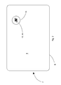
Figure 2 is an embodiment of a document with an RFID device according to the invention; -
Figures 3 and 4 show an insert with an RFID device that is incorporable into a document according to the invention; -
Figure 5 is a cross section of the insert illustrated in -
Figures 3 and 4 ; -
Figure 6 shows a perspective view of a semifinished product that is usable in making a document with an incorporated RIFD device according to the invention; -
Figure 7 is a longitudinal section of the semifinished product shown inFigure 6 . - In
Figure 1 aticket 1 according to the prior art is shown, with anRFID device 4 incorporated therein. Theticket 1 consists of afirst layer 2, of paper or plastics, and of asecond layer 3, of paper or plastics, between which theRFID device 4 is inserted that consists of anantenna 5 connected to amicrochip 6. - The
first layer 2, thesecond layer 3 and theRFID device 4 are laminated together, to obtain theticket 1. - This lamination operation involves the need to align together with precision the
first layer 2, thesecond layer 3 and the RFID device to prevent defective alignment in the subsequent cutting operation being able cause the RFID device of theticket 1 to be destroyed or the front and back images not to be aligned. - The lamination operation thus has a significant impact on the production costs of the
ticket 1. - Further, if both faces of the
ticket 1 are intended to be printed, two printing operations are necessary, a first printing operation to print the face of thelayer 1 intended to face the exterior of the finishedticket 1 and a second printing operation to print the face of thelayer 2 intended to face the exterior of the finishedticket 2. - Also this dual printing operation contributes to increasing the production costs of the
ticket 1. - Currently, in most applications RFID devices on a UHF band are used that are progressively replacing RFID devices on an HF band.
- The RFID devices on a UHF band, compared with the RFID devices on an HF band, have the advantage of requiring an antenna of very small dimensions, even of just a few millimetres in width or diameter, which enables RFID devices of very small dimensions to be made.
- The present invention aims to use this type of RFID device on a UHF band to simplify making documents, for example tickets, or cards, into which an RFID device has been incorporated.
- In
Figure 2 adocument 7 is illustrated that is made according to the present invention. - The
document 7, for example a ticket or a card, consists of asubstratum 8 made from a single layer of paper or plastics, said substratum constituting the body of thedocument 7. Thesubstratum 8 can be printed beforehand on both sides, for example with decorative patterns, images, or wordings. On anexternal face 9 of thesubstratum 8 anRFID device 10 on a UHF band is applied, for example by heat transfer or gluing, theRFID device 10 on a UHF band consisting of anantenna 12 connected to amicrochip 13 and applied, together with themicrochip 13, to a supportingelement 11, or formed thereupon and then connected to themicrochip 13. TheRFID device 10, after being applied to theface 9 of thesubstratum 8, can be covered with a coveringelement 14, which may consist of a hologram, or a lamina, or a film, or an image, for example a logo, which are applied, for example, by heat transfer or pressure, or by any other known transfer technique. Alternatively, the coveringelement 14 may consist of a print element made, for example, by silkscreen printing after theRFID device 10 has been applied to thesubstratum 8. - Alternatively, the supporting
element 11 may act as a covering element, applying theRFID device 10 to thesubstratum 8, in such a manner that the face of the supportingelement 11 to which theRFID device 10 is applied faces thesubstratum 8. In this case, the face of the supportingelement 11 opposite the one on which theRFID device 10 is applied can be provided with printing graphic elements. - The
RFID device 10 with anypossible covering element 14, if it is applied directly to the surface of thesubstratum 8, protrudes slightly therefrom and can cause stacking difficulties and be exposed to undesired stress, for example, if thedocument 7 is inserted into pocket of a document holder by sliding thedocument 7 against the walls of the pocket, which could lead to theRFID device 10 being damaged. - This problem, as illustrated in
Figure 4 , can be solved, in the case of a document made of plastic material, by making arecess 15 beforehand on theface 9 of thesubstratum 8, to which theRFID device 10 has to be applied, therecess 15 being made for example by milling, into which theRFID device 10 is inserted, together with thepossible covering element 14. The depth of therecess 15 has to be such that theRFID device 10, with the supportingelement 11 and with thepossible covering element 14, does not protrude from the surface of theface 9. In other words, the depth of therecess 15 has to correspond substantially to the sum of the thicknesses of theRFID device 10, of the supportingelement 11 and of thepossible covering element 14, such that the assembly consisting of theRFID device 10, the supportingelement 11 and thepossible covering element 14 does not protrude from the surface of theface 9 after being inserted into therecess 15. - In the case of a document made of paper material it is advantageous to make the document with two layers of paper material, in one of which an opening is made intended for receiving the
RFID device 10 with the supportingelement 11 and thepossible covering element 14. - In
Figures 6 and 7 making adocument 7 according to the aforesaid method is illustrated. - A
first layer 16 and asecond layer 17, made of paper material, are coupled together, which each have dimensions that are substantially equal to a multiple of the dimensions of asingle document 7, obtaining asubstratum 18 made of sheet paper material, by means of which a plurality ofdocuments 7 will be made that will be subsequently separated from one another singly, or in a roll or in a pack. - The
layers substratum 18, or it is possible to print thesubstratum 18 after coupling, possibly on both sides. On thefirst layer 16, or on thesecond layer 17, holes 19 are provided that, after coupling of thesecond layer 17 with thefirst layer 16, define seats into which theRFID devices 10 can be inserted, with the supportingelements 11 thereof and thepossible cover elements 14. The thickness of thelayer holes 19 are made, is chosen substantially according to the sum of the thicknesses of theRFID device 10, of the supportingelement 11 and of thepossible covering element 14, such that theRFID devices 10, with the respective supportingelements 11 andpossible cover elements 14, after being inserted into theholes 10, do not protrude from the surface of thesubstratum 18. - After the
devices RFID 10 have been inserted into theholes 19 and therespective cover elements 14 have been possibly applied thereupon, thesubstratum 18 is cut to be divided into parts to obtain a plurality ofdocuments 7, singly or in a roll or in a pack, each with arespective RFID device 10 incorporated therein. - Instead of using layers of 16, 17 made of paper material that have dimensions that are multiples of the dimensions of one
document 7 it is possible to use layers of paper material having dimensions that are equal to the dimensions of thedocuments 7 so as to make thedocuments 7 singly.
Claims (16)
- Method for making a document (7) with an RFID device (10) on a UHF band associated therewith, characterised in that it comprises the following steps:- providing a substratum (8; 18) intended for constituting the body of at least one document (7);- applying to an external face (9) of said substratum (8; 18) at least one RFID device (10) on a UHF band comprising a supporting element (11) on a first face of which there is an antenna (12) connected to a microchip (13), said applying occurring in such a manner that said RFID device (10), after being applied to said substratum (8; 18), is covered by said supporting element (11).
- Method according to claim 1, further comprising printing graphic elements on a second face of said supporting element (11) opposite said first face, said printing occurring before said applying.
- Method according to claim 1, further comprising covering said at least one RFID device (10) with a respective covering element (14), said covering element (14) being able to consist of printed graphic elements, or of a lamina, a hologram or a film, which may be printed before said covering.
- Method according to claim 3 in which said covering element (14) is applied by transfer.
- Method according to any preceding claim, wherein said substratum (8) is made of plastic material.
- Method according to claim 5, and further comprising making on a face (9) of said substratum (8) a recess (15) intended for housing said RFID device (10), said recess having a thickness corresponding at least to the sum of the thicknesses of said RFID device (10) and of said supporting element (11).
- Method according to claim 6, as appended to claim 3, or 4, wherein said recess (15) has a depth substantially corresponding to the sum of the thicknesses of said RFID device (10), of said supporting element (11) and of said covering element (14).
- Method according to any one of claims 1 to 4, wherein said substratum (18) is made of paper material.
- Method according to claim 5, or 8, and further comprising:- making said substratum (18) coupling together a first layer (16) and a second layer (17) of said material, said first layer (16), or said second layer (17), being provided with a plurality of holes (19);- inserting into each of said holes (19) an RFID device (10) with the respective supporting element (11).
- Method according to claim 9, and further comprising inserting into each of said holes (19) a respective covering element (14) of said RFID device (10).
- Document (7) with an RFID device (10) on a UHF band associated therewith, said RFID device (10) comprising a supporting element (11) on a first face of which there is an antenna (12) connected to a microchip (13), said document (7) comprising a substratum (8; 18), characterised in that said RFID device (10) is applied to an external face (9) of said substratum (8; 18) such as to be covered by said supporting element (11).
- Document (7) according to claim 11, wherein on a second face of said supporting element (11) opposite said first face graphic printing elements are printed.
- Document (7) according to claim 11, further comprising a covering element (14) that covers said RFID device (10), said covering element (14) being able to consist of printed graphic elements, or of a lamina, a hologram or a film, which is possibly printed.
- Document (7) according to any one of claims 11 to 13, wherein said substratum (8) is made of plastic material and said face (9) is provided with a recess (15) intended for housing said RFID device (10) with said supporting element (11) and possibly said covering element (14).
- Document (7) according to any one of claims 11 to 13, wherein said substratum comprises a first layer (16) and a second layer (17) made of plastic or paper material, coupled together, said first layer (16), or said second layer (17), being provided with a hole (19) intended for housing said RFID device (10) with said supporting element (11) and possibly said covering element (14).
- RFID device (10) on a UHF band comprising a supporting element (11), on a first face of which an antenna (12) is applied that is connected to a microchip (13), and a possible covering element (14) of said antenna (12) and of said microchip (13), characterised in that on a second face of said supporting element (11) opposite said first face, or on said covering element (14), graphic elements are printed, said covering element being able to consist of a lamina, a hologram, or a film.
Applications Claiming Priority (1)
| Application Number | Priority Date | Filing Date | Title |
|---|---|---|---|
| ITMO2009A000318A IT1397389B1 (en) | 2009-12-30 | 2009-12-30 | DOCUMENT WITH BUILT-IN RFID DEVICE AND ITS MANUFACTURING METHOD |
Publications (2)
| Publication Number | Publication Date |
|---|---|
| EP2343673A2 true EP2343673A2 (en) | 2011-07-13 |
| EP2343673A3 EP2343673A3 (en) | 2012-01-11 |
Family
ID=42184113
Family Applications (1)
| Application Number | Title | Priority Date | Filing Date |
|---|---|---|---|
| EP10197117A Withdrawn EP2343673A3 (en) | 2009-12-30 | 2010-12-28 | Document incorporating an RFID device and manufacturing method thereof |
Country Status (2)
| Country | Link |
|---|---|
| EP (1) | EP2343673A3 (en) |
| IT (1) | IT1397389B1 (en) |
Cited By (1)
| Publication number | Priority date | Publication date | Assignee | Title |
|---|---|---|---|---|
| EP3680099A1 (en) * | 2018-12-07 | 2020-07-15 | Alberto Pavan | Process for making a multilayer sheet, multilayer sheet and products obtained therewith |
Citations (2)
| Publication number | Priority date | Publication date | Assignee | Title |
|---|---|---|---|---|
| DE102006052516A1 (en) * | 2006-11-06 | 2008-05-08 | Bielomatik Leuze Gmbh + Co Kg | Self-adhesive RFID tag and method for its production |
| WO2009014499A1 (en) * | 2007-07-20 | 2009-01-29 | Stickkey Security Access Pte L | A radio frequency transponder |
Family Cites Families (3)
| Publication number | Priority date | Publication date | Assignee | Title |
|---|---|---|---|---|
| EP1035503B2 (en) * | 1999-01-23 | 2010-03-03 | X-ident technology GmbH | RFID-Transponder with printable surface |
| US6369711B1 (en) * | 2000-06-09 | 2002-04-09 | Intermec Ip Corp | Profile corrected label with RFID transponder and method for making same |
| DE20018648U1 (en) * | 2000-11-02 | 2001-03-01 | Idento - Gesellschaft für industrielle Kennzeichnung mbH, 63322 Rödermark | Transponder label |
-
2009
- 2009-12-30 IT ITMO2009A000318A patent/IT1397389B1/en active
-
2010
- 2010-12-28 EP EP10197117A patent/EP2343673A3/en not_active Withdrawn
Patent Citations (2)
| Publication number | Priority date | Publication date | Assignee | Title |
|---|---|---|---|---|
| DE102006052516A1 (en) * | 2006-11-06 | 2008-05-08 | Bielomatik Leuze Gmbh + Co Kg | Self-adhesive RFID tag and method for its production |
| WO2009014499A1 (en) * | 2007-07-20 | 2009-01-29 | Stickkey Security Access Pte L | A radio frequency transponder |
Cited By (1)
| Publication number | Priority date | Publication date | Assignee | Title |
|---|---|---|---|---|
| EP3680099A1 (en) * | 2018-12-07 | 2020-07-15 | Alberto Pavan | Process for making a multilayer sheet, multilayer sheet and products obtained therewith |
Also Published As
| Publication number | Publication date |
|---|---|
| EP2343673A3 (en) | 2012-01-11 |
| IT1397389B1 (en) | 2013-01-10 |
| ITMO20090318A1 (en) | 2011-06-30 |
Similar Documents
| Publication | Publication Date | Title |
|---|---|---|
| KR100766643B1 (en) | Method for manufacturing a contactless hybrid smart card using an antenna support made of fibrous material | |
| US9224085B2 (en) | Electronic passport | |
| CN102982365B (en) | The manufacture method of transponder label and transponder label | |
| EP1406209A2 (en) | Non-contact card with transponder placed in cavity of the card | |
| EP3083169B1 (en) | Method and device for putting in place an insert in a cavity formed in a foil product | |
| US8397996B2 (en) | Portable data carrier and method for the production of the data carrier | |
| US8534561B2 (en) | Antenna-forming insert and chip card including it | |
| KR102375805B1 (en) | Rf tag metal card with double-sided recognition and method of manufacturing the smae | |
| EP4260233B1 (en) | Method for manufacturing a smart card with positioning of a metal insert | |
| EP2343673A2 (en) | Document incorporating an RFID device and manufacturing method thereof | |
| US20040062016A1 (en) | Medium having data storage and communication capabilites and method for forming same | |
| AU2005211867A1 (en) | Identification document and method for the production thereof | |
| JP7250565B2 (en) | IC card and manufacturing method thereof | |
| US10970612B2 (en) | Interactive core for electronic cards | |
| US20160192485A1 (en) | Electronic entity with coupling integrated between a microcircuit and an antenna and method of fabrication | |
| KR102413682B1 (en) | Metal card and manufacturing method thereof | |
| JP4882187B2 (en) | Contactless IC card and contactless IC card sending medium | |
| JP2000153681A (en) | Booklet-shaped printed matter having a non-contact IC storage medium | |
| JP4826040B2 (en) | Non-contact IC card, non-contact IC card sending medium, and manufacturing method thereof | |
| KR20060113824A (en) | How to prevent dimples when mounting smart card chip | |
| US20170270397A1 (en) | Data Carrier Comprising a Partial Piece | |
| US10558905B2 (en) | Method for producing a device comprising at least one electronic element associated with a substrate and an antenna | |
| GB2404627A (en) | Passport booklet and its manufacture | |
| AT506621A1 (en) | SMART CARD | |
| KR20130085746A (en) | Braille card and manufacturing method thereof |
Legal Events
| Date | Code | Title | Description |
|---|---|---|---|
| PUAI | Public reference made under article 153(3) epc to a published international application that has entered the european phase |
Free format text: ORIGINAL CODE: 0009012 |
|
| AK | Designated contracting states |
Kind code of ref document: A2 Designated state(s): AL AT BE BG CH CY CZ DE DK EE ES FI FR GB GR HR HU IE IS IT LI LT LU LV MC MK MT NL NO PL PT RO RS SE SI SK SM TR |
|
| AX | Request for extension of the european patent |
Extension state: BA ME |
|
| PUAL | Search report despatched |
Free format text: ORIGINAL CODE: 0009013 |
|
| AK | Designated contracting states |
Kind code of ref document: A3 Designated state(s): AL AT BE BG CH CY CZ DE DK EE ES FI FR GB GR HR HU IE IS IT LI LT LU LV MC MK MT NL NO PL PT RO RS SE SI SK SM TR |
|
| AX | Request for extension of the european patent |
Extension state: BA ME |
|
| RIC1 | Information provided on ipc code assigned before grant |
Ipc: G06K 19/077 20060101AFI20111202BHEP Ipc: G06K 19/07 20060101ALI20111202BHEP |
|
| 17P | Request for examination filed |
Effective date: 20120711 |
|
| RAP1 | Party data changed (applicant data changed or rights of an application transferred) |
Owner name: SMART RES SOCIETA' PER AZIONI |
|
| RIN1 | Information on inventor provided before grant (corrected) |
Inventor name: LOLLI, MARCELLO |
|
| 17Q | First examination report despatched |
Effective date: 20140416 |
|
| GRAP | Despatch of communication of intention to grant a patent |
Free format text: ORIGINAL CODE: EPIDOSNIGR1 |
|
| INTG | Intention to grant announced |
Effective date: 20181114 |
|
| STAA | Information on the status of an ep patent application or granted ep patent |
Free format text: STATUS: THE APPLICATION IS DEEMED TO BE WITHDRAWN |
|
| 18D | Application deemed to be withdrawn |
Effective date: 20190326 |