EP2343588A1 - Image display apparatus - Google Patents
Image display apparatus Download PDFInfo
- Publication number
- EP2343588A1 EP2343588A1 EP10189795A EP10189795A EP2343588A1 EP 2343588 A1 EP2343588 A1 EP 2343588A1 EP 10189795 A EP10189795 A EP 10189795A EP 10189795 A EP10189795 A EP 10189795A EP 2343588 A1 EP2343588 A1 EP 2343588A1
- Authority
- EP
- European Patent Office
- Prior art keywords
- image display
- optical system
- light
- polarized light
- polarization splitting
- Prior art date
- Legal status (The legal status is an assumption and is not a legal conclusion. Google has not performed a legal analysis and makes no representation as to the accuracy of the status listed.)
- Withdrawn
Links
- 230000003287 optical effect Effects 0.000 claims abstract description 164
- 230000010287 polarization Effects 0.000 claims abstract description 144
- 238000005286 illumination Methods 0.000 claims abstract description 47
- 238000000926 separation method Methods 0.000 claims description 27
- 230000006835 compression Effects 0.000 claims description 6
- 238000007906 compression Methods 0.000 claims description 6
- 239000010408 film Substances 0.000 description 79
- 239000004973 liquid crystal related substance Substances 0.000 description 62
- 238000006243 chemical reaction Methods 0.000 description 14
- 238000009826 distribution Methods 0.000 description 10
- 230000001902 propagating effect Effects 0.000 description 5
- 230000009467 reduction Effects 0.000 description 5
- 241000276498 Pollachius virens Species 0.000 description 2
- 230000008033 biological extinction Effects 0.000 description 2
- 239000011159 matrix material Substances 0.000 description 2
- 238000000034 method Methods 0.000 description 2
- 230000004048 modification Effects 0.000 description 2
- 238000012986 modification Methods 0.000 description 2
- 238000002834 transmittance Methods 0.000 description 2
- 230000009471 action Effects 0.000 description 1
- 230000008901 benefit Effects 0.000 description 1
- 239000003086 colorant Substances 0.000 description 1
- 230000000694 effects Effects 0.000 description 1
- QSHDDOUJBYECFT-UHFFFAOYSA-N mercury Chemical compound [Hg] QSHDDOUJBYECFT-UHFFFAOYSA-N 0.000 description 1
- 229910052753 mercury Inorganic materials 0.000 description 1
- 239000012788 optical film Substances 0.000 description 1
- 230000000644 propagated effect Effects 0.000 description 1
- 238000002310 reflectometry Methods 0.000 description 1
- 238000001228 spectrum Methods 0.000 description 1
- 230000007480 spreading Effects 0.000 description 1
- 238000009827 uniform distribution Methods 0.000 description 1
Images



Classifications
-
- G—PHYSICS
- G02—OPTICS
- G02B—OPTICAL ELEMENTS, SYSTEMS OR APPARATUS
- G02B27/00—Optical systems or apparatus not provided for by any of the groups G02B1/00 - G02B26/00, G02B30/00
- G02B27/28—Optical systems or apparatus not provided for by any of the groups G02B1/00 - G02B26/00, G02B30/00 for polarising
- G02B27/283—Optical systems or apparatus not provided for by any of the groups G02B1/00 - G02B26/00, G02B30/00 for polarising used for beam splitting or combining
-
- G—PHYSICS
- G02—OPTICS
- G02B—OPTICAL ELEMENTS, SYSTEMS OR APPARATUS
- G02B27/00—Optical systems or apparatus not provided for by any of the groups G02B1/00 - G02B26/00, G02B30/00
- G02B27/0018—Optical systems or apparatus not provided for by any of the groups G02B1/00 - G02B26/00, G02B30/00 with means for preventing ghost images
-
- G—PHYSICS
- G03—PHOTOGRAPHY; CINEMATOGRAPHY; ANALOGOUS TECHNIQUES USING WAVES OTHER THAN OPTICAL WAVES; ELECTROGRAPHY; HOLOGRAPHY
- G03B—APPARATUS OR ARRANGEMENTS FOR TAKING PHOTOGRAPHS OR FOR PROJECTING OR VIEWING THEM; APPARATUS OR ARRANGEMENTS EMPLOYING ANALOGOUS TECHNIQUES USING WAVES OTHER THAN OPTICAL WAVES; ACCESSORIES THEREFOR
- G03B21/00—Projectors or projection-type viewers; Accessories therefor
- G03B21/14—Details
- G03B21/145—Housing details, e.g. position adjustments thereof
-
- G—PHYSICS
- G03—PHOTOGRAPHY; CINEMATOGRAPHY; ANALOGOUS TECHNIQUES USING WAVES OTHER THAN OPTICAL WAVES; ELECTROGRAPHY; HOLOGRAPHY
- G03B—APPARATUS OR ARRANGEMENTS FOR TAKING PHOTOGRAPHS OR FOR PROJECTING OR VIEWING THEM; APPARATUS OR ARRANGEMENTS EMPLOYING ANALOGOUS TECHNIQUES USING WAVES OTHER THAN OPTICAL WAVES; ACCESSORIES THEREFOR
- G03B21/00—Projectors or projection-type viewers; Accessories therefor
- G03B21/14—Details
- G03B21/20—Lamp housings
-
- G—PHYSICS
- G03—PHOTOGRAPHY; CINEMATOGRAPHY; ANALOGOUS TECHNIQUES USING WAVES OTHER THAN OPTICAL WAVES; ELECTROGRAPHY; HOLOGRAPHY
- G03B—APPARATUS OR ARRANGEMENTS FOR TAKING PHOTOGRAPHS OR FOR PROJECTING OR VIEWING THEM; APPARATUS OR ARRANGEMENTS EMPLOYING ANALOGOUS TECHNIQUES USING WAVES OTHER THAN OPTICAL WAVES; ACCESSORIES THEREFOR
- G03B21/00—Projectors or projection-type viewers; Accessories therefor
- G03B21/14—Details
- G03B21/20—Lamp housings
- G03B21/2073—Polarisers in the lamp house
-
- G—PHYSICS
- G03—PHOTOGRAPHY; CINEMATOGRAPHY; ANALOGOUS TECHNIQUES USING WAVES OTHER THAN OPTICAL WAVES; ELECTROGRAPHY; HOLOGRAPHY
- G03B—APPARATUS OR ARRANGEMENTS FOR TAKING PHOTOGRAPHS OR FOR PROJECTING OR VIEWING THEM; APPARATUS OR ARRANGEMENTS EMPLOYING ANALOGOUS TECHNIQUES USING WAVES OTHER THAN OPTICAL WAVES; ACCESSORIES THEREFOR
- G03B21/00—Projectors or projection-type viewers; Accessories therefor
- G03B21/14—Details
- G03B21/28—Reflectors in projection beam
-
- H—ELECTRICITY
- H04—ELECTRIC COMMUNICATION TECHNIQUE
- H04N—PICTORIAL COMMUNICATION, e.g. TELEVISION
- H04N9/00—Details of colour television systems
- H04N9/12—Picture reproducers
- H04N9/31—Projection devices for colour picture display, e.g. using electronic spatial light modulators [ESLM]
- H04N9/3141—Constructional details thereof
- H04N9/315—Modulator illumination systems
- H04N9/3167—Modulator illumination systems for polarizing the light beam
Definitions
- the present invention relates to an image display apparatus and more particularly to an image display apparatus using a reflective image display element.
- a polarizing beam splitter allowing P-polarized light to pass through it, but reflecting S-polarized light is arranged on the incident/emergent surface side of the reflective liquid crystal panel.
- the characteristic of a polarization splitting film used in the polarizing beam splitter depends on the incidence angle of the incident light. As the incidence angle of the light incident upon the polarization splitting film departs from 45° to a larger extent, leakage light from the polarization splitting film is increased and the contrast of a projected image is reduced.
- the term "leakage light” implies light entering a projection lens when the liquid crystal panel is driven in a mode where all pixels are displayed black.
- the present invention in its first aspect provides an image display apparatus as specified in claims 1 to 4.
- the present invention in its second aspect provides an image display apparatus as specified in claims 5 and 6.
- the present invention in its third aspect provides an image display apparatus as specified in claim 7.
- the present invention in its fourth aspect provides an image display apparatus as specified in claim 8.
- the present invention in its fifth aspect provides an image display apparatus as specified in claim 9.
- the present invention in its sixth aspect provides an image display apparatus as specified in claim 10.
- the present invention in its seventh aspect provides an image display apparatus as specified in claim 11.
- the present invention in its eighth aspect provides an image display apparatus as specified in claim 12.
- the present invention in its ninth aspect provides an image display apparatus as specified in claim 13.
- the present invention in its tenth aspect provides an image display apparatus as specified in claim 14.
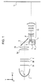
- Fig. 1 illustrates an image display apparatus according to a first embodiment of the present invention.
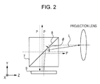
- Fig. 2 is an enlarged view of a polarizing beam splitter, an image display element, and thereabout.
- Figs. 3A and 3B are each a graph illustrating the relationship between an incidence angle of light incident upon a polarization splitting film and a characteristic of the polarization splitting film.
- Fig. 4 is an illustration to explain leakage light from the polarizing beam splitter.
- Fig. 5 illustrates an angular distribution of the leakage light from the polarization splitting film in the first embodiment.
- Fig. 6 illustrates a quantity of light that can be captured by a projection lens, and an angular distribution of the quantity of light captured.
- Figs. 7A and 7B are each a sectional view of an image display apparatus according to a second embodiment of the present invention.
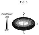
- Fig. 8 illustrates an angular distribution of the leakage light from the polarization splitting film in the second embodiment.
- Fig. 9 illustrates an image display apparatus according to a third embodiment of the present invention.
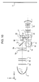
- Fig. 10 illustrates an image display apparatus according to a fourth embodiment of the present invention.
- Fig. 1 illustrates the configuration of an image display apparatus according to a first embodiment.
- reference numeral 1 denotes a light source.
- a reflector 2 reflects light emitted from the light source 1 in a predetermined direction.
- a parabolic reflector is used as the reflector 2.
- a first fly-eye lens 3a is made up of rectangular lens elements which are each similar in shape to a panel and which are arranged in a matrix pattern.
- a second fly-eye lens 3b includes lens elements that correspond respectively to the individual rectangular lens elements of the first fly-eye lens 3a.
- a polarization conversion element 4 converts unpolarized light from the light source 1 to linearly-polarized light.
- Reference numerals 5a and 5b each denote a condenser lens, and 6 denotes a reflecting mirror.
- Reference numeral 7 denotes a polarizing beam splitter, and 8 denotes a polarization splitting film of the polarizing beam splitter 7.
- a reflective liquid crystal panel (image display element) 9 displays an image by controlling the polarization state of the incident light.
- Reference numeral 10 denotes a projection lens (projection optical system), and 11 denotes a screen (projection plane). The projection lens is mounted into a mounting slot (mounting portion), which is formed in a main body of the image display apparatus.
- a line segment L represents an optical path of a light beam emerging from the center of the image display element and reaching a point where an optical axis of the projection lens 10 intersects an optical surface within the projection lens 10 (projection optical system), which is closest to an illumination optical system (generally, such a point is given as an apex of the lens surface of the relevant optical surface).
- the projection lens support i.e., the mounting slot for the projection lens
- angle ⁇ formed by the optical path L and the polarization splitting film 8 of the polarizing beam splitter 7 is smaller than 45°
- angle ⁇ formed by the optical path L and the polarization splitting film 8 of the polarizing beam splitter 7 is smaller than 45°
- the "optical surface within the projection optical system, which is closest to an illumination optical system” implies, for example, a lens surface of the projection lens 10 on the side closest to the liquid crystal panel 9, or closest to the polarizing beam splitter 7.
- the polarizing beam splitter 7 may have a refractive index n of 1.6 or more.
- the refractive index n of the polarizing beam splitter 7 used in this embodiment is 1.8.
- a light beam emerging from the center of the liquid crystal panel 9 in a direction vertical (perpendicular) to the liquid crystal panel 9 and incident upon the polarization splitting film 8 forms an angle of 45° with respect to the surface of the polarization splitting film 8.
- a horizontal one-dot-chain line in Fig. 1 represents each of an optical axis of the condenser lens 5a and the optical axis of the projection lens 10.
- a vertical one-dot-chain line extending from the reflecting mirror 6 to the liquid crystal panel 9 represents a line normal to the liquid crystal panel 9 and passing substantially through the center of the polarization splitting film 8.
- the light emitted from the light source 1 is reflected by the reflector 2 to advance as substantially parallel light, which enters the first fly-eye lens 3a.
- the substantially parallel light is separated into a plurality of light beams by individual lens elements forming the first fly-eye lens 3a.
- the plural divided light beams pass through the second fly-eye lens 3b and enter the polarization conversion element 4.
- the polarization conversion element 4 includes a plurality of small polarizing beam splitters each having a polarization splitting film and a half-wave plate arranged at alternate ones of emergent surfaces of the small polarizing beam splitters. Unpolarized light having entered the polarization conversion element 4 exits it after being converted to P-polarized light (i.e., a light beam in the P-polarized state).
- the conversion to the S-polarized light can be performed by arranging a half-wave plate on the emergent side of the P-polarized light.
- the liquid crystal panel 9 is arranged on the side toward which the light incident upon the polarizing beam splitter 7 is reflected.
- the P-polarized light and the S-polarized light are defined with respect to the polarization splitting film 8 of the polarizing beam splitter 7, which is adjacent to the liquid crystal panel (image display element) 9, rather than with respect to the small polarizing beam splitters of the polarization conversion element 4.
- the P-polarized light converted by the polarization conversion element 4 is introduced to the reflecting mirror 6 while being converged by the condenser lenses 5a and 5b.
- An optical system from the light source 1 to the condenser lenses 5a and 5b constitutes an illumination optical system that illuminates the liquid crystal panel 9 with Koehler illumination.
- the converged light exiting the condenser lenses 5a and 5b is reflected by the reflecting mirror 6 to enter the polarizing beam splitter 7.
- the P-polarized light passes through the polarization splitting film 8 of the polarizing beam splitter 7 for illumination of the liquid crystal panel 9.
- the incident light is modulated by the liquid crystal panel 9, and the modulated emergent light is reflected by the polarizing beam splitter 7 to be projected onto a screen 11 through the projection lens 10 (projection optical system).
- a Z-axis in Fig. 1 is parallel to the optical axis of the projection lens 10, and the direction toward the screen 11 is assumed to be a + Z-direction.
- An X-axis is perpendicular to a plane including the Z-axis and a line normal to the polarization splitting film 8, and the direction toward the front side of the drawing sheet (as seen from the reader's point of view) is assumed to be a + X-direction.
- a Y-axis is perpendicular to both the X-axis and the Z-axis, and the direction toward the upper side of the drawing sheet from the lower side is assumed to be a + Y-direction.
- Fig. 2 is an enlarged view of the polarizing beam splitter 7, the liquid crystal panel (image display element) 9, and thereabout in Fig. 1 .
- An angle ⁇ formed by the optical path L (denoted by a solid line in Fig. 2 ) and the polarization splitting film 8 is smaller than 45°.
- an arrow denoted by a broken line P represents a light beam generated in the mode where all pixels are displayed black.
- the P-polarized light reflected by the reflecting mirror 6 passes through the polarization splitting film 8 and enters the liquid crystal panel 9.
- the P-polarized light having entered the liquid crystal panel 9 is reflected as it is without being converted in the polarization direction thereof in the mode where all pixels are displayed black.
- the reflected P-polarized light passes through the polarization splitting film 8 again and returns to the light source side. Most of the reflected P-polarized light returns to the light source side due to the characteristic of the polarization splitting film 8. However, some of the reflected P-polarized light is reflected by the polarization splitting film 8 to enter the projection lens 10 in spite of being the P-polarized light.
- Fig. 3A is a graph illustrating changes in the characteristic of the polarization splitting film 8 with respect to changes in the incidence angle of light incident upon the polarization splitting film 8 in an XY-section (i.e., in the X-direction).
- Fig. 3B is a graph illustrating changes in the characteristic of the polarization splitting film 8 with respect to changes in the incidence angle of light incident upon the polarization splitting film 8 in a YZ-section (i.e., in the Y-direction).
- the horizontal axis represents a wavelength (nm) and the vertical axis (Rp) represents reflectivity (%) of the P-polarized light.
- a solid line represents the characteristic of the polarization splitting film 8 for a light beam incident upon the polarization splitting film 8 at the incidence angle of 45°.
- a broken line represents the characteristic of the polarization splitting film 8 for a light beam incident upon the polarization splitting film 8 at the incidence angle that is smaller than 45° by about 5°.
- a one-dot-chain line represents the characteristic of the polarization splitting film 8 for a light beam incident upon the polarization splitting film 8 at the incidence angle that is larger than 45° by about 5°.
- the polarization splitting film 8 having the characteristics illustrated in Figs. 3A and 3B is designed so as to exhibit satisfactory performance in a band corresponding to a green wavelength range of 500 to 580 (nm) where the relative luminosity factor is maximum among the spectrum of the light source used in the image display apparatus.
- the characteristic of the polarization splitting film 8 varies to a larger extent when the incidence angle is changed in the YZ-section than when the incidence angle is changed in the XY-section.
- the polarization splitting film 8 exhibits a better characteristic with respect to changes in the incidence angle in the XY-section (i.e., in the X-direction) than with respect to changes in the incidence angle in the YZ-section (i.e., in the Y-direction).
- the thickness of the polarization splitting film 8 through which the line beam entering the polarization splitting film 8 at the incidence angle of 45° with respect to the line normal to the polarization splitting film 8 passes is increased (namely, the optical path is lengthened) when the incidence angle of the light beam is changed by +5° in the Y-direction, and it is reduced (namely, the optical path is shortened) when the incidence angle of the light beam is changed by -5° in the Y-direction. Further, it is seen that the position (indicated by an arrow in Fig.
- FIG. 4 illustrates, in a more easily understandable manner, how the quantity of leakage light changes (becomes less or more) depending on the incidence angle in the same section as that of Fig. 2 .
- the leakage of the light (P-polarized light) reflected at a certain point on the liquid crystal panel 9 and diverging to some extent is less in the + Y-direction and is more in the - Y-direction on the emergent surface side of the polarizing beam splitter 7.
- Fig. 5 illustrates the incidence angle of the light beam entering the polarization splitting film 8 and a distribution of the leakage light in the XY-section when the liquid crystal panel 9 is driven in the mode where a projected image is displayed totally black.
- Each coordinate axis represents the incidence angle upon the polarization splitting film 8, and a deviation from an angle of 45° is 0° at the center (origin).
- the quantity of leakage light is less in a lighter black portion and is more in a denser black portion.
- the coordinate axes in Fig. 5 correspond to those in Figs. 1 to 4 , and the description of the coordinate axes is omitted. As seen from Fig. 5 , though described above with reference to Fig.
- the quantity of leakage light causing a reduction of the contrast is symmetric in the X-direction, but it is asymmetric in the Y-direction.
- the quantity of leakage light is more significantly increased in the - Y-direction.
- the angular distribution of the leakage light, illustrated in Fig. 5 can be confirmed by actually displaying a totally black image in the image display apparatus, and by observing the light from the image display element directly on the screen in a state where the projection lens is removed.
- a light beam reflected at and diverging from a point on the liquid crystal panel 9, which is away from the point thereon corresponding to the center of the optical axis of the projection lens 10, is cut off in part of its components within a particular angular range due to vignetting by the projection lens 10.
- the term "vignetting" implies that, as an incident light beam is inclined at a larger angle with respect to the optical axis of the projection lens 10, the incident light beam becomes harder to pass through the entirety of a diaphragm due to the size and the thickness of the lens.
- a projection lens of an image display apparatus is used in such a way that the direction of projection of the projection lens is set obliquely. In the configuration of Fig.
- FIG. 6 illustrates a quantity of the light capable being captured by the projection lens, which is arranged as illustrated in Fig. 1 , and an angular distribution of the light quantity when a light beam having a substantially uniform distribution in light quantity enters the projection lens.
- the influence of the vignetting is less and a loss of the light quantity capable being captured by the projection lens is small in the + Y-direction.
- the light quantity capable being captured by the projection lens is reduced in the - Y-direction due to the influence of the vignetting.
- the projection lens 10 is arranged with respect to the image display element (liquid crystal panel) 9 as follows, taking into consideration the angular distribution of the leakage light, illustrated in Fig. 5 , which is resulted based on the characteristic of the polarization splitting film 8. Assuming the optical path L of the light beam that emerges from the center of the liquid crystal panel 9 and reaches the point where the optical axis of the projection lens 10 intersects the optical surface within the projection lens 10, which is closest to the illumination optical system, the projection lens 10 is arranged such that the angle ⁇ formed by the optical path L and the polarization splitting film 8 of the polarizing beam splitter 7 is smaller than 45°.
- the projection lens 10 and the mounting slot (mounting portion) for the projection lens 10 are arranged such that the incidence angle and the emergence angle of the light beam propagating along the optical path L with respect to the normal to the polarization splitting film 8 is larger than 45°.
- the optical axis of the projection lens i.e., the axis of the projection lens passing the center of the mounting slot
- the leakage light generated at the polarization splitting film can be effectively cut off by utilizing the influence of the vignetting that is caused within the projection lens.
- the optical axis of the projection lens 10 is aligned with a point where the quantity of leakage light from the polarization splitting film 8 is at its minimum. As a result, the quantity of leakage light included in the projected image is reduced and the contrast of the projected image is improved.
- Figs. 7A and 7B illustrate an image display apparatus according to a second embodiment of the present invention.
- the second embodiment differs from the first embodiment in that an illumination optical system in the second embodiment has the function of compressing a light beam in each of a first section (XZ-section) and a second section (YZ-section), each of which includes an optical axis of the illumination optical system and which are orthogonal to each other.
- Fig. 7A is a sectional view, taken along the XZ-section, of the image display apparatus according to the second embodiment
- Fig. 7B is a sectional view, taken along the YZ-section, of the image display apparatus according to the second embodiment.
- reference numeral 1 denotes a light source.
- a reflector 2 reflects light emitted from the light source 1 in a predetermined direction.
- Reference numeral 12 denotes a convex lens (positive lens).
- Reference numeral 13 denotes a concave cylindrical lens (specifically, a lens having negative refractive power in the X-direction and having no refractive power in the Y-direction), and 14 denotes a concave cylindrical lens (specifically, a lens having no refractive power in the X-direction and having negative refractive power in the Y-direction).
- reference numeral 13 denotes a first negative cylindrical lens
- 14 denotes a second negative cylindrical lens.
- a first fly-eye lens 3a is made up of rectangular lens elements which are each similar in shape to a panel and which are arranged in a matrix pattern.
- a second fly-eye lens 3b includes lens elements that correspond respectively to the individual rectangular lens elements of the first fly-eye lens 3a.
- a polarization conversion element 4 has the function of converting unpolarized light from the light source 1 to linearly-polarized light.
- Reference numerals 5a and 5b each denote a condenser lens, and 6 denotes a reflecting mirror.
- Reference numeral 10 denotes a projection lens (projection optical system), and 11 denotes a screen (projection plane).
- the condenser lenses 5a and 5b may be a single convex lens.
- a highpressure mercury lamp is used as the light source 1
- a parabolic mirror is used as the reflector 2.
- a mounting slot for mounting the projection lens 10 is formed in a main body of the image display apparatus, and the projection lens 10 is mounted into the mounting slot.
- the light emitted from the light source 1 is collected by the reflector 2 and enters the convex lens 12.
- the light is converged by the convex lens 12 and enters the concave cylindrical lens 13.
- the convex lens 12 and the concave cylindrical lens (negative cylindrical lens) 13 the light becomes substantially parallel light in the X-direction in the XZ-section of Fig. 7A .
- the light having entered the first fly-eye lens 3a is separated into a plurality of light beams by individual lens elements forming the first fly-eye lens 3a.
- the plural divided light beams having passed through the first fly-eye lens 3a enter the concave cylindrical lens 14 and exit it as substantially parallel light beams in the YZ-section of Fig.
- the light modulated by the liquid crystal panel 9 is reflected by the polarization splitting film 8 of the polarizing beam splitter 7 and is projected onto the screen 11 through the projection lens 10.
- the liquid crystal panel 9 reflects the P-polarized light without converting the polarization direction thereof.
- the light reflected by the liquid crystal panel 9 returns toward the light source side after passing through the polarization splitting film 8.
- Koehler illumination is performed for the liquid crystal panel 9 by arranging the light source 1 and the second fly-eye lens 3b in conjugate positions and by arranging the first fly-eye lens 3a and the liquid crystal panel 9 in conjugate positions.
- the characteristic of the polarization splitting film 8 varies and leakage light causing a reduction of the contrast is generated depending on changes in the angle at which the light beam reflected by the liquid crystal panel 9 enters the polarization splitting film 8 of the polarizing beam splitter 7.
- Fig. 8 illustrates an angular distribution of the leakage light at the polarization splitting film 8 when the light beam is modulated by the liquid crystal panel into the polarization state corresponding to a totally black image.
- Each coordinate axis in Fig. 8 represents the incidence angle upon the polarization splitting film 8, and a deviation from an angle of 45° is 0° at the center (origin).
- the quantity of leakage light is less in a lighter black portion and is more in a denser black portion.
- the coordinate axes in Fig. 8 correspond to those in Fig. 7 , and the description of the coordinate axes is omitted.
- the light beam is compressed in both the X-direction and the Y-direction independently, and a compression rate of the light beam in the Y-axis direction is higher than that in the first embodiment.
- an angle ⁇ formed by the optical path L and a film boundary line of the polarization splitting film 8 in the YZ-plane is set to be smaller than 45° (namely, the incidence angle and the emergence angle of the light beam propagating along the optical path L with respect to the polarization splitting film 8 is set to be larger than 45°). Accordingly, the leakage light generated in the - Y-direction can be effectively cut off by utilizing the influence of the vignetting that is caused within the projection lens. As a result, the contrast of the projected image can be improved without inserting, e.g., a polarizer to cut off the leakage light.
- the compression rate of the light beam is set different between the X-direction and the Y-direction such that the light beam is more strongly compressed in the Y-direction
- spreading of the incidence angle upon the polarization splitting film 8 can be reduced in the Y-direction in which the characteristic of the polarization splitting film 8 varies to a larger extent.
- the quantity of leakage light can be reduced in the second embodiment in comparison with the case of compressing the light beam in the X-direction and the Y-direction at the same rate.
- compression used in this specification implies an optical action of making the width of a light beam after exiting an optical system, which is substantially afocal, smaller than that of the light beam before entering the optical system, and the term “compression” rate implies a rate of the compression.
- Fig. 9 illustrates an image display apparatus according to a third embodiment of the present invention. The following description is made about only different points from the configuration of Fig. 1 .
- the polarization conversion element 4 converts the incident light to P-polarized light.
- Reference numeral 15 denotes a dichroic mirror (color separation element), and 16 denotes a wavelength selective phase plate that acts upon only light in a red wavelength band to rotate the polarization direction of the light through 90°.
- Reference numerals 17 and 18 denote a first polarizing beam splitter and a second polarizing beam splitter, respectively.
- Reference numeral 19 denotes a reflective liquid crystal panel for red (first image display element), 20 denotes a reflective liquid crystal panel for green (second image display element), and 21 denotes a reflective liquid crystal panel for blue (third image display element).
- a combining prism (combining element) 22 reflects light in a green wavelength band and transmits light in red and blue wavelength bands therethrough.
- a one-dot-chain line in Fig. 9 represents the optical axis of each of the condenser lens 5a and the optical axis of the projection lens 10.
- the dichroic mirror 15 and the first and second polarizing beam splitters 17 and 18 are arranged such that a plane including a color separation surface of the dichroic mirror 15 perpendicularly intersects a plane including polarized-light separation surfaces of the first and second polarizing beam splitters 17 and 18.
- the light beam having exited the condenser lens 5b enters the dichroic mirror 15.
- the dichroic mirror 15 transmits only light in the green wavelength band (first-color light) therethrough, and reflects light in the blue and red wavelength bands (second-color light and third-color light).
- the light in the green wavelength band passes through the polarizing beam splitter 17 (first polarizing beam splitter) for illumination of the liquid crystal panel 20 for green.
- S-polarized light converted from the incident light by the liquid crystal panel 20 for green is reflected by the polarizing beam splitter 17 and is further reflected by the combining prism 22 to be projected onto the projection plane (screen) 11 through the projection lens 10.
- Light having not been converted in the polarization direction by the liquid crystal panel 20 passes through the polarizing beam splitter 17 again for return to the light source side.
- the wavelength selective phase plate 16 acts upon only the red-band light to rotate the polarization direction thereof through 90° for conversion to S-polarized light.
- the red-band light having been converted to the S-polarized light is reflected by a polarization splitting film of the polarizing beam splitter 18 (second polarizing beam splitter) and enters the liquid crystal panel 19 for red.
- the red-band light having been converted to P-polarized light by the liquid crystal panel 19 passes through both the polarizing beam splitter 18 and the combining prism 22 to be projected onto the projection plane (screen) 11 through the projection lens 10.
- S-polarized red-band light having been not converted by the liquid crystal panel 19 is reflected by the polarization splitting film of the polarizing beam splitter 18 for return to the light source side.
- the blue-band light having been reflected by the dichroic mirror 15 passes through the wavelength selective phase plate 16 and further passes through the polarizing beam splitter 18 to enter the liquid crystal panel 21 for blue.
- the blue-band light having been converted from P-polarized light to S-polarized light upon entering the liquid crystal panel 21 for blue is reflected by the polarizing beam splitter 18 and passes through the combining prism 22 to be projected onto the projection plane (screen) 11 through the projection lens 10.
- the P-polarized blue-band light having been not converted by the liquid crystal panel 21 passes through the polarizing beam splitter 18 for return to the light source side.
- the characteristic of the polarization splitting film varies and leakage light causing a reduction of the contrast is generated depending on changes in the angle at which the light beam reflected by the liquid crystal panel 20 enters the polarization splitting film of the polarizing beam splitter 17.
- the extinction ratio of the P-polarized light is reduced with respect to changes in the incidence angle corresponding to a reduction of the thickness of the polarization splitting film 8 through which the light beam passes.
- an angle ⁇ formed by the optical path L and a film boundary line of the polarization splitting film of the polarizing beam splitter 17 in the YZ-section is set to be smaller than 45° (namely, the incidence angle and the emergence angle of the light beam propagating along the optical path L with respect to the polarization splitting film is set to be larger than 45°). Accordingly, the leakage light generated in the - Y-direction can be effectively cut off by utilizing the influence of the vignetting that is caused within the projection lens.
- the leakage light can be suppressed without arranging a polarizer, which has low transmittance, on the emergent side of the polarizing beam splitter.
- the contrast of the projected image can be improved while minimizing a reduction of brightness of the projected image.
- the projection lens 10 and the mounting slot for the projection lens 10 are arranged such that, in the direction in which the polarizing beam splitter 17 and the combining element 22 are aligned (i.e., in the Y-direction), the optical axis of the projection lens 10 is shifted parallel toward the polarizing beam splitter 17 relative to an emergent path of the light beam from the combining element (prism) 22, which has propagated along an optical path aligned with the optical axis of the illumination optical system, (i.e., relative to a path of the incident light upon the projection lens 10).
- the size of the image display (projection) apparatus can be reduced in the direction in which the optical axis of the projection lens 10 (i.e., an axis passing the center of the mounting slot for the projection lens 10) is shifted (namely, in the Y-direction in Fig. 9 ).
- the optical axis of the projection lens 10 is arranged between the combining prism 22 and the polarizing beam splitter 17, i.e., at a more inner position within a housing.
- Fig. 10 illustrates an image display apparatus according to a fourth embodiment of the present invention.
- the image display apparatus according to the fourth embodiment differs from that according to the third embodiment, illustrated in Fig. 9 , in the arrangement of the liquid crystal panel 20 for green with respect to the polarizing beam splitter 17 (first polarizing beam splitter).
- a half-wavelength plate 30 is disposed between the dichroic mirror 15 and the polarizing beam splitter 17. Because the remaining configuration is the same as that in the third embodiment, the following description is made only about different points from the configuration of the third embodiment.
- the liquid crystal panel 20 is arranged such that the liquid crystal panel 20 is illuminated with the light reflected from the polarizing beam splitter 17. Because the green-band illumination light having passed through the dichroic mirror 15 is converted to the P-polarized light by the polarization conversion element 4, it is not reflected by the polarizing beam splitter 17 if it remains as the P-polarized light. In this fourth embodiment, therefore, the half-wavelength plate 30 is disposed between the dichroic mirror 15 and the polarizing beam splitter 17 for converting the polarization direction of the illumination light to the S-polarization.
- the green-band illumination light having been substantially converted to the S-polarized light is selectively reflected by the polarizing beam splitter 17 for illumination of the liquid crystal panel 20.
- P-polarized light obtained with the conversion by the liquid crystal panel 20 passes through the polarizing beam splitter 17 and is reflected by the combining prism 22 to be projected onto the projection plane (screen) 11 through the projection lens 10.
- the light having been not converted in the polarization direction thereof by the liquid crystal panel 20 is reflected by the polarizing beam splitter 17 again for return to the light source side.
- an angle ⁇ formed by the optical path L and the polarization splitting film of the polarizing beam splitter 17 in the YZ-section is set to be smaller than 45° (namely, the incidence angle and the emergence angle of the light beam propagating along the optical path L with respect to the polarization splitting film is set to be larger than 45°).
- the degree of freedom in layout of the projection lens 10 is increased.
- the size of the image display (projection) apparatus can be reduced by effectively utilizing the space where the liquid crystal panel 20 is positioned in Fig. 9 , for shifting of the projection lens 10.
- the arrangement capable of providing the advantage of the fourth embodiment is not limited to that illustrated in Fig. 10 .
- the liquid crystal panel 20 is similarly not required to be arranged at the position toward which the projection lens is shifted.
- the present invention is not limited to those embodiments and can be variously modified and changed within the scope of the invention.
- the light source may be a laser beam source emitting linearly-polarized light.
- the characteristic of the dichroic mirror 15 and the characteristic of the combining prism 22 may be changed respectively to transmit the red-band light therethrough and to transmit the blue-band light and the green-band light therethrough.
- the present invention can be applied to an image display apparatus in which a cross-dichroic prism is employed and three polarizing beam splitters are arranged corresponding to liquid crystal panels for three colors, respectively.
- the image display apparatus ensuring high contrast of the projected image can be provided.
- An image display apparatus includes an image display element (9) configured to display an image by controlling a polarization state of a polarized light beam.
- An illumination optical system (3a, 3b, 4, 5a, 5b, 6) guides the polarized light beam to the image display element.
- a polarizing beam splitter (7) disposed between the illumination optical system and the image display element selectively splits polarization of incident light.
- a projection optical system (10) projects the image displayed by the image display element onto a projection plane (11). The positional relationship between the polarizing beam splitter and an optical axis of the projection optical system is properly set.
Landscapes
- Physics & Mathematics (AREA)
- General Physics & Mathematics (AREA)
- Optics & Photonics (AREA)
- Engineering & Computer Science (AREA)
- Multimedia (AREA)
- Signal Processing (AREA)
- Projection Apparatus (AREA)
- Liquid Crystal (AREA)
- Optical Elements Other Than Lenses (AREA)
- Microscoopes, Condenser (AREA)
- Polarising Elements (AREA)
Abstract
Description
- The present invention relates to an image display apparatus and more particularly to an image display apparatus using a reflective image display element.
- In a known image display apparatus using a reflective liquid crystal panel (image display element), respective optical paths of light incident upon and light emergent from the liquid crystal panel need to be made different from each other. For that purpose, a polarizing beam splitter allowing P-polarized light to pass through it, but reflecting S-polarized light is arranged on the incident/emergent surface side of the reflective liquid crystal panel. The characteristic of a polarization splitting film used in the polarizing beam splitter depends on the incidence angle of the incident light. As the incidence angle of the light incident upon the polarization splitting film departs from 45° to a larger extent, leakage light from the polarization splitting film is increased and the contrast of a projected image is reduced. The term "leakage light" implies light entering a projection lens when the liquid crystal panel is driven in a mode where all pixels are displayed black.
- There is known a technique of arranging an analyzer, which cuts off the leakage light, on the emergent surface side of the polarizing beam splitter in order to increase the contrast of the projected image. However, the known technique has the problem that brightness of the projected image is reduced because a polarizer has low transmittance.
- The present invention in its first aspect provides an image display apparatus as specified in
claims 1 to 4. - The present invention in its second aspect provides an image display apparatus as specified in
claims 5 and 6. - The present invention in its third aspect provides an image display apparatus as specified in
claim 7. - The present invention in its fourth aspect provides an image display apparatus as specified in
claim 8. - The present invention in its fifth aspect provides an image display apparatus as specified in
claim 9. - The present invention in its sixth aspect provides an image display apparatus as specified in
claim 10. - The present invention in its seventh aspect provides an image display apparatus as specified in
claim 11. - The present invention in its eighth aspect provides an image display apparatus as specified in
claim 12. - The present invention in its ninth aspect provides an image display apparatus as specified in
claim 13. - The present invention in its tenth aspect provides an image display apparatus as specified in
claim 14. - Further features of the present invention will become apparent from the following description of exemplary embodiments with reference to the attached drawings.
-
Fig. 1 illustrates an image display apparatus according to a first embodiment of the present invention. -
Fig. 2 is an enlarged view of a polarizing beam splitter, an image display element, and thereabout. -
Figs. 3A and 3B are each a graph illustrating the relationship between an incidence angle of light incident upon a polarization splitting film and a characteristic of the polarization splitting film. -
Fig. 4 is an illustration to explain leakage light from the polarizing beam splitter. -
Fig. 5 illustrates an angular distribution of the leakage light from the polarization splitting film in the first embodiment. -
Fig. 6 illustrates a quantity of light that can be captured by a projection lens, and an angular distribution of the quantity of light captured. -
Figs. 7A and 7B are each a sectional view of an image display apparatus according to a second embodiment of the present invention. -
Fig. 8 illustrates an angular distribution of the leakage light from the polarization splitting film in the second embodiment. -
Fig. 9 illustrates an image display apparatus according to a third embodiment of the present invention. -
Fig. 10 illustrates an image display apparatus according to a fourth embodiment of the present invention. - Embodiments of the present invention will be described below with reference to the drawings.
-
Fig. 1 illustrates the configuration of an image display apparatus according to a first embodiment. InFig. 1 ,reference numeral 1 denotes a light source. Areflector 2 reflects light emitted from thelight source 1 in a predetermined direction. In this embodiment, a parabolic reflector is used as thereflector 2. A first fly-eye lens 3a is made up of rectangular lens elements which are each similar in shape to a panel and which are arranged in a matrix pattern. A second fly-eye lens 3b includes lens elements that correspond respectively to the individual rectangular lens elements of the first fly-eye lens 3a. Apolarization conversion element 4 converts unpolarized light from thelight source 1 to linearly-polarized light.Reference numerals Reference numeral 7 denotes a polarizing beam splitter, and 8 denotes a polarization splitting film of the polarizingbeam splitter 7. A reflective liquid crystal panel (image display element) 9 displays an image by controlling the polarization state of the incident light.Reference numeral 10 denotes a projection lens (projection optical system), and 11 denotes a screen (projection plane). The projection lens is mounted into a mounting slot (mounting portion), which is formed in a main body of the image display apparatus. - A line segment L represents an optical path of a light beam emerging from the center of the image display element and reaching a point where an optical axis of the
projection lens 10 intersects an optical surface within the projection lens 10 (projection optical system), which is closest to an illumination optical system (generally, such a point is given as an apex of the lens surface of the relevant optical surface). The projection lens support (i.e., the mounting slot for the projection lens) is arranged such that an angle θ formed by the optical path L and the polarization splittingfilm 8 of the polarizingbeam splitter 7 is smaller than 45°. The expression "angle θ formed by the optical path L and the polarization splittingfilm 8 of the polarizingbeam splitter 7 is smaller than 45°" implies that an incidence angle and an emergence angle of a light beam propagating along the optical path L with respect to the normal to the polarization splittingfilm 8 is larger than 45°. Further, the "optical surface within the projection optical system, which is closest to an illumination optical system" implies, for example, a lens surface of theprojection lens 10 on the side closest to theliquid crystal panel 9, or closest to the polarizingbeam splitter 7. - The polarizing
beam splitter 7 may have a refractive index n of 1.6 or more. The refractive index n of the polarizingbeam splitter 7 used in this embodiment is 1.8. Further, a light beam emerging from the center of theliquid crystal panel 9 in a direction vertical (perpendicular) to theliquid crystal panel 9 and incident upon the polarization splittingfilm 8 forms an angle of 45° with respect to the surface of the polarization splittingfilm 8. A horizontal one-dot-chain line inFig. 1 represents each of an optical axis of thecondenser lens 5a and the optical axis of theprojection lens 10. A vertical one-dot-chain line extending from the reflectingmirror 6 to theliquid crystal panel 9 represents a line normal to theliquid crystal panel 9 and passing substantially through the center of the polarization splittingfilm 8. - The light emitted from the
light source 1 is reflected by thereflector 2 to advance as substantially parallel light, which enters the first fly-eye lens 3a. The substantially parallel light is separated into a plurality of light beams by individual lens elements forming the first fly-eye lens 3a. The plural divided light beams pass through the second fly-eye lens 3b and enter thepolarization conversion element 4. Thepolarization conversion element 4 includes a plurality of small polarizing beam splitters each having a polarization splitting film and a half-wave plate arranged at alternate ones of emergent surfaces of the small polarizing beam splitters. Unpolarized light having entered thepolarization conversion element 4 exits it after being converted to P-polarized light (i.e., a light beam in the P-polarized state). When unpolarized light is to be converted to S-polarized light, the conversion to the S-polarized light can be performed by arranging a half-wave plate on the emergent side of the P-polarized light. In that case, theliquid crystal panel 9 is arranged on the side toward which the light incident upon thepolarizing beam splitter 7 is reflected. Herein, the P-polarized light and the S-polarized light are defined with respect to thepolarization splitting film 8 of thepolarizing beam splitter 7, which is adjacent to the liquid crystal panel (image display element) 9, rather than with respect to the small polarizing beam splitters of thepolarization conversion element 4. The P-polarized light converted by thepolarization conversion element 4 is introduced to the reflectingmirror 6 while being converged by thecondenser lenses light source 1 to thecondenser lenses liquid crystal panel 9 with Koehler illumination. - The converged light exiting the
condenser lenses mirror 6 to enter thepolarizing beam splitter 7. The P-polarized light passes through thepolarization splitting film 8 of thepolarizing beam splitter 7 for illumination of theliquid crystal panel 9. The incident light is modulated by theliquid crystal panel 9, and the modulated emergent light is reflected by thepolarizing beam splitter 7 to be projected onto ascreen 11 through the projection lens 10 (projection optical system). A Z-axis inFig. 1 is parallel to the optical axis of theprojection lens 10, and the direction toward thescreen 11 is assumed to be a + Z-direction. An X-axis is perpendicular to a plane including the Z-axis and a line normal to thepolarization splitting film 8, and the direction toward the front side of the drawing sheet (as seen from the reader's point of view) is assumed to be a + X-direction. A Y-axis is perpendicular to both the X-axis and the Z-axis, and the direction toward the upper side of the drawing sheet from the lower side is assumed to be a + Y-direction. -
Fig. 2 is an enlarged view of thepolarizing beam splitter 7, the liquid crystal panel (image display element) 9, and thereabout inFig. 1 . An angle θ formed by the optical path L (denoted by a solid line inFig. 2 ) and thepolarization splitting film 8 is smaller than 45°. Also, an arrow denoted by a broken line P represents a light beam generated in the mode where all pixels are displayed black. The P-polarized light reflected by the reflectingmirror 6 passes through thepolarization splitting film 8 and enters theliquid crystal panel 9. The P-polarized light having entered theliquid crystal panel 9 is reflected as it is without being converted in the polarization direction thereof in the mode where all pixels are displayed black. The reflected P-polarized light passes through thepolarization splitting film 8 again and returns to the light source side. Most of the reflected P-polarized light returns to the light source side due to the characteristic of thepolarization splitting film 8. However, some of the reflected P-polarized light is reflected by thepolarization splitting film 8 to enter theprojection lens 10 in spite of being the P-polarized light. -
Fig. 3A is a graph illustrating changes in the characteristic of thepolarization splitting film 8 with respect to changes in the incidence angle of light incident upon thepolarization splitting film 8 in an XY-section (i.e., in the X-direction).Fig. 3B is a graph illustrating changes in the characteristic of thepolarization splitting film 8 with respect to changes in the incidence angle of light incident upon thepolarization splitting film 8 in a YZ-section (i.e., in the Y-direction). In each of the graphs ofFigs. 3A and 3B , the horizontal axis represents a wavelength (nm) and the vertical axis (Rp) represents reflectivity (%) of the P-polarized light. InFigs. 3A and 3B , as the percentage of Rp becomes smaller, the value of an extinction ratio becomes higher and a more satisfactory characteristic of thepolarization splitting film 8 is obtained. Further, in each of those graphs, a solid line represents the characteristic of thepolarization splitting film 8 for a light beam incident upon thepolarization splitting film 8 at the incidence angle of 45°. A broken line represents the characteristic of thepolarization splitting film 8 for a light beam incident upon thepolarization splitting film 8 at the incidence angle that is smaller than 45° by about 5°. A one-dot-chain line represents the characteristic of thepolarization splitting film 8 for a light beam incident upon thepolarization splitting film 8 at the incidence angle that is larger than 45° by about 5°. In addition, thepolarization splitting film 8 having the characteristics illustrated inFigs. 3A and 3B is designed so as to exhibit satisfactory performance in a band corresponding to a green wavelength range of 500 to 580 (nm) where the relative luminosity factor is maximum among the spectrum of the light source used in the image display apparatus. - As seen from
Figs. 3A and 3B , when the incidence angle of the light beam is changed in different directions by the same angle on the basis of the light beam that enters thepolarization splitting film 8 at 45° with respect to a line normal to thepolarization splitting film 8, the characteristic of thepolarization splitting film 8 varies to a larger extent when the incidence angle is changed in the YZ-section than when the incidence angle is changed in the XY-section. In other words, thepolarization splitting film 8 exhibits a better characteristic with respect to changes in the incidence angle in the XY-section (i.e., in the X-direction) than with respect to changes in the incidence angle in the YZ-section (i.e., in the Y-direction). - Let more closely look at the changes in the characteristic of the
polarization splitting film 8 with respect to the changes in the incidence angle in the YZ-section, which are illustrated inFig. 3B . Comparing the characteristics of thepolarization splitting film 8 resulting when the incidence angle is changed by +5° and -5° in the YZ-section, it is seen that the changes in the characteristic of thepolarization splitting film 8 behaves in a way differing from that in the case ofFig. 3A . The reason is that, on the basis of the thickness of thepolarization splitting film 8 through which the line beam entering thepolarization splitting film 8 at the incidence angle of 45° with respect to the line normal to thepolarization splitting film 8 passes, the thickness of thepolarization splitting film 8 through which the incident light beam passes is increased (namely, the optical path is lengthened) when the incidence angle of the light beam is changed by +5° in the Y-direction, and it is reduced (namely, the optical path is shortened) when the incidence angle of the light beam is changed by -5° in the Y-direction. Further, it is seen that the position (indicated by an arrow inFig. 3B ) of a peak of the characteristic curve in the graph shifts toward the shorter wavelength side when the incidence angle is 45+5° and toward the longer wavelength side when the incidence angle is 45-5°. As known in the art, a characteristic of an optical film generally shifts toward the longer wavelength side when a film thickness through which a light beam passes is shortened, and it shifts toward the shorter wavelength side when a film thickness through which a light beam passes is lengthened. Therefore, when light including a green wavelength range (500 to 580 nm) enters thepolarization splitting film 8, the quantity of leakage light is less when the incidence angle is 45+α° than when the incidence angle is 45-α°.Fig. 4 illustrates, in a more easily understandable manner, how the quantity of leakage light changes (becomes less or more) depending on the incidence angle in the same section as that ofFig. 2 . As illustrated inFig. 4 , the leakage of the light (P-polarized light) reflected at a certain point on theliquid crystal panel 9 and diverging to some extent is less in the + Y-direction and is more in the - Y-direction on the emergent surface side of thepolarizing beam splitter 7. -
Fig. 5 illustrates the incidence angle of the light beam entering thepolarization splitting film 8 and a distribution of the leakage light in the XY-section when theliquid crystal panel 9 is driven in the mode where a projected image is displayed totally black. Each coordinate axis represents the incidence angle upon thepolarization splitting film 8, and a deviation from an angle of 45° is 0° at the center (origin). The quantity of leakage light is less in a lighter black portion and is more in a denser black portion. The coordinate axes inFig. 5 correspond to those inFigs. 1 to 4 , and the description of the coordinate axes is omitted. As seen fromFig. 5 , though described above with reference toFig. 3 , the quantity of leakage light causing a reduction of the contrast is symmetric in the X-direction, but it is asymmetric in the Y-direction. In particular, the quantity of leakage light is more significantly increased in the - Y-direction. The angular distribution of the leakage light, illustrated inFig. 5 , can be confirmed by actually displaying a totally black image in the image display apparatus, and by observing the light from the image display element directly on the screen in a state where the projection lens is removed. - An angular distribution of the light capable of being captured by the
projection lens 10 will be described below. Let now look at a route along which the light advances to theprojection lens 10 from theliquid crystal panel 9 while diverging and then reaches thescreen 11 through theprojection lens 10. A light beam reflected at and diverging from the center of theliquid crystal panel 9 inFig. 1 , i.e., from a point on theliquid crystal panel 9 corresponding to the center of the optical axis of theprojection lens 10, is captured in all components within an angular range defined by the F-number of theprojection lens 10. However, a light beam reflected at and diverging from a point on theliquid crystal panel 9, which is away from the point thereon corresponding to the center of the optical axis of theprojection lens 10, is cut off in part of its components within a particular angular range due to vignetting by theprojection lens 10. The term "vignetting" implies that, as an incident light beam is inclined at a larger angle with respect to the optical axis of theprojection lens 10, the incident light beam becomes harder to pass through the entirety of a diaphragm due to the size and the thickness of the lens. In general, a projection lens of an image display apparatus (projector) is used in such a way that the direction of projection of the projection lens is set obliquely. In the configuration ofFig. 1 , an image is projected in an obliquely upward direction. When an image is projected in such an oblique direction, an angular distribution of the light capable of being captured by the projection lens becomes also asymmetric in the Y-direction due to the vignetting. For reference,Fig. 6 illustrates a quantity of the light capable being captured by the projection lens, which is arranged as illustrated inFig. 1 , and an angular distribution of the light quantity when a light beam having a substantially uniform distribution in light quantity enters the projection lens. As seen fromFig. 6 , the influence of the vignetting is less and a loss of the light quantity capable being captured by the projection lens is small in the + Y-direction. On the other hand, the light quantity capable being captured by the projection lens is reduced in the - Y-direction due to the influence of the vignetting. - In this embodiment, the
projection lens 10 is arranged with respect to the image display element (liquid crystal panel) 9 as follows, taking into consideration the angular distribution of the leakage light, illustrated inFig. 5 , which is resulted based on the characteristic of thepolarization splitting film 8. Assuming the optical path L of the light beam that emerges from the center of theliquid crystal panel 9 and reaches the point where the optical axis of theprojection lens 10 intersects the optical surface within theprojection lens 10, which is closest to the illumination optical system, theprojection lens 10 is arranged such that the angle θ formed by the optical path L and thepolarization splitting film 8 of thepolarizing beam splitter 7 is smaller than 45°. Stated another way, theprojection lens 10 and the mounting slot (mounting portion) for theprojection lens 10 are arranged such that the incidence angle and the emergence angle of the light beam propagating along the optical path L with respect to the normal to thepolarization splitting film 8 is larger than 45°. - Thus, according to the first embodiment, since the optical axis of the projection lens (i.e., the axis of the projection lens passing the center of the mounting slot) is shifted to the side where the quantity of leakage light is less, the leakage light generated at the polarization splitting film can be effectively cut off by utilizing the influence of the vignetting that is caused within the projection lens. In other words, the optical axis of the
projection lens 10 is aligned with a point where the quantity of leakage light from thepolarization splitting film 8 is at its minimum. As a result, the quantity of leakage light included in the projected image is reduced and the contrast of the projected image is improved. -
Figs. 7A and 7B illustrate an image display apparatus according to a second embodiment of the present invention. The second embodiment differs from the first embodiment in that an illumination optical system in the second embodiment has the function of compressing a light beam in each of a first section (XZ-section) and a second section (YZ-section), each of which includes an optical axis of the illumination optical system and which are orthogonal to each other.Fig. 7A is a sectional view, taken along the XZ-section, of the image display apparatus according to the second embodiment, andFig. 7B is a sectional view, taken along the YZ-section, of the image display apparatus according to the second embodiment. - In
Figs. 7A and 7B ,reference numeral 1 denotes a light source. Areflector 2 reflects light emitted from thelight source 1 in a predetermined direction.Reference numeral 12 denotes a convex lens (positive lens).Reference numeral 13 denotes a concave cylindrical lens (specifically, a lens having negative refractive power in the X-direction and having no refractive power in the Y-direction), and 14 denotes a concave cylindrical lens (specifically, a lens having no refractive power in the X-direction and having negative refractive power in the Y-direction). In other words,reference numeral 13 denotes a first negative cylindrical lens, and 14 denotes a second negative cylindrical lens. A first fly-eye lens 3a is made up of rectangular lens elements which are each similar in shape to a panel and which are arranged in a matrix pattern. A second fly-eye lens 3b includes lens elements that correspond respectively to the individual rectangular lens elements of the first fly-eye lens 3a. Apolarization conversion element 4 has the function of converting unpolarized light from thelight source 1 to linearly-polarized light.Reference numerals Reference numeral 7 denotes a polarizing beam splitter, 8 denotes a polarization splitting film, and 9 denotes a reflective liquid crystal panel (image display element).Reference numeral 10 denotes a projection lens (projection optical system), and 11 denotes a screen (projection plane). Thecondenser lenses light source 1, and a parabolic mirror is used as thereflector 2. As in the first embodiment, a mounting slot for mounting theprojection lens 10 is formed in a main body of the image display apparatus, and theprojection lens 10 is mounted into the mounting slot. - The light emitted from the
light source 1 is collected by thereflector 2 and enters theconvex lens 12. The light is converged by theconvex lens 12 and enters the concavecylindrical lens 13. Through theconvex lens 12 and the concave cylindrical lens (negative cylindrical lens) 13, the light becomes substantially parallel light in the X-direction in the XZ-section ofFig. 7A . The light having entered the first fly-eye lens 3a is separated into a plurality of light beams by individual lens elements forming the first fly-eye lens 3a. The plural divided light beams having passed through the first fly-eye lens 3a enter the concavecylindrical lens 14 and exit it as substantially parallel light beams in the YZ-section ofFig. 7B by the cooperated action of theconvex lens 12 and the concavecylindrical lens 14 positioned at the front of the second fly-eye lens 3b. The light beams compressed in each of the XZ-section and the YZ-section pass through the second fly-eye lens 3b and enter thepolarization conversion element 4. P-polarized light converted from the incident light upon thepolarization conversion element 4 is converged by thecondenser lenses mirror 6 to enter thepolarizing beam splitter 7. The light having entered thepolarizing beam splitter 7 passes through thepolarization splitting film 8 for illumination of theliquid crystal panel 9. In a mode where pixels are displayed white, theliquid crystal panel 9 modulates the P-polarized light into S-polarized light. The light modulated by theliquid crystal panel 9 is reflected by thepolarization splitting film 8 of thepolarizing beam splitter 7 and is projected onto thescreen 11 through theprojection lens 10. In the mode where the pixels are displayed black, theliquid crystal panel 9 reflects the P-polarized light without converting the polarization direction thereof. The light reflected by theliquid crystal panel 9 returns toward the light source side after passing through thepolarization splitting film 8. Also in the illumination optical system of the second embodiment, Koehler illumination is performed for theliquid crystal panel 9 by arranging thelight source 1 and the second fly-eye lens 3b in conjugate positions and by arranging the first fly-eye lens 3a and theliquid crystal panel 9 in conjugate positions. - In the second embodiment, as in the first embodiment, the characteristic of the
polarization splitting film 8 varies and leakage light causing a reduction of the contrast is generated depending on changes in the angle at which the light beam reflected by theliquid crystal panel 9 enters thepolarization splitting film 8 of thepolarizing beam splitter 7.Fig. 8 illustrates an angular distribution of the leakage light at thepolarization splitting film 8 when the light beam is modulated by the liquid crystal panel into the polarization state corresponding to a totally black image. Each coordinate axis inFig. 8 represents the incidence angle upon thepolarization splitting film 8, and a deviation from an angle of 45° is 0° at the center (origin). The quantity of leakage light is less in a lighter black portion and is more in a denser black portion. The coordinate axes inFig. 8 correspond to those inFig. 7 , and the description of the coordinate axes is omitted. In the second embodiment, the light beam is compressed in both the X-direction and the Y-direction independently, and a compression rate of the light beam in the Y-axis direction is higher than that in the first embodiment. - Further, as in the first embodiment, assuming an optical path L of the light beam that emerges from the center of the
liquid crystal panel 9 and reaches the point where the optical axis of theprojection lens 10 intersects the optical surface within theprojection lens 10, which is closest to the illumination optical system, an angle θ formed by the optical path L and a film boundary line of thepolarization splitting film 8 in the YZ-plane is set to be smaller than 45° (namely, the incidence angle and the emergence angle of the light beam propagating along the optical path L with respect to thepolarization splitting film 8 is set to be larger than 45°). Accordingly, the leakage light generated in the - Y-direction can be effectively cut off by utilizing the influence of the vignetting that is caused within the projection lens. As a result, the contrast of the projected image can be improved without inserting, e.g., a polarizer to cut off the leakage light. - As additional advantageous effect of the second embodiment, since the compression rate of the light beam is set different between the X-direction and the Y-direction such that the light beam is more strongly compressed in the Y-direction, spreading of the incidence angle upon the
polarization splitting film 8 can be reduced in the Y-direction in which the characteristic of thepolarization splitting film 8 varies to a larger extent. As a result, the quantity of leakage light can be reduced in the second embodiment in comparison with the case of compressing the light beam in the X-direction and the Y-direction at the same rate. The term "compression" used in this specification implies an optical action of making the width of a light beam after exiting an optical system, which is substantially afocal, smaller than that of the light beam before entering the optical system, and the term "compression" rate implies a rate of the compression. -
Fig. 9 illustrates an image display apparatus according to a third embodiment of the present invention. The following description is made about only different points from the configuration ofFig. 1 . Thepolarization conversion element 4 converts the incident light to P-polarized light.Reference numeral 15 denotes a dichroic mirror (color separation element), and 16 denotes a wavelength selective phase plate that acts upon only light in a red wavelength band to rotate the polarization direction of the light through 90°.Reference numerals Reference numeral 19 denotes a reflective liquid crystal panel for red (first image display element), 20 denotes a reflective liquid crystal panel for green (second image display element), and 21 denotes a reflective liquid crystal panel for blue (third image display element). A combining prism (combining element) 22 reflects light in a green wavelength band and transmits light in red and blue wavelength bands therethrough. A one-dot-chain line inFig. 9 represents the optical axis of each of thecondenser lens 5a and the optical axis of theprojection lens 10. Thedichroic mirror 15 and the first and secondpolarizing beam splitters dichroic mirror 15 perpendicularly intersects a plane including polarized-light separation surfaces of the first and secondpolarizing beam splitters - The light beam having exited the
condenser lens 5b enters thedichroic mirror 15. Of the incident light beam, thedichroic mirror 15 transmits only light in the green wavelength band (first-color light) therethrough, and reflects light in the blue and red wavelength bands (second-color light and third-color light). The light in the green wavelength band passes through the polarizing beam splitter 17 (first polarizing beam splitter) for illumination of theliquid crystal panel 20 for green. S-polarized light converted from the incident light by theliquid crystal panel 20 for green is reflected by thepolarizing beam splitter 17 and is further reflected by the combiningprism 22 to be projected onto the projection plane (screen) 11 through theprojection lens 10. Light having not been converted in the polarization direction by theliquid crystal panel 20 passes through thepolarizing beam splitter 17 again for return to the light source side. - The light in the red and blue wavelength bands, which has been reflected by the
dichroic mirror 15, passes through the wavelengthselective phase plate 16. The wavelengthselective phase plate 16 acts upon only the red-band light to rotate the polarization direction thereof through 90° for conversion to S-polarized light. The red-band light having been converted to the S-polarized light is reflected by a polarization splitting film of the polarizing beam splitter 18 (second polarizing beam splitter) and enters theliquid crystal panel 19 for red. The red-band light having been converted to P-polarized light by theliquid crystal panel 19 passes through both thepolarizing beam splitter 18 and the combiningprism 22 to be projected onto the projection plane (screen) 11 through theprojection lens 10. S-polarized red-band light having been not converted by theliquid crystal panel 19 is reflected by the polarization splitting film of thepolarizing beam splitter 18 for return to the light source side. - The blue-band light having been reflected by the
dichroic mirror 15 passes through the wavelengthselective phase plate 16 and further passes through thepolarizing beam splitter 18 to enter theliquid crystal panel 21 for blue. The blue-band light having been converted from P-polarized light to S-polarized light upon entering theliquid crystal panel 21 for blue is reflected by thepolarizing beam splitter 18 and passes through the combiningprism 22 to be projected onto the projection plane (screen) 11 through theprojection lens 10. The P-polarized blue-band light having been not converted by theliquid crystal panel 21 passes through thepolarizing beam splitter 18 for return to the light source side. - As described above in the first embodiment, the characteristic of the polarization splitting film varies and leakage light causing a reduction of the contrast is generated depending on changes in the angle at which the light beam reflected by the
liquid crystal panel 20 enters the polarization splitting film of thepolarizing beam splitter 17. - Looking here at the leakage light in the green wavelength band, which most contributes to brightness of a projected image, as in the first embodiment, the extinction ratio of the P-polarized light is reduced with respect to changes in the incidence angle corresponding to a reduction of the thickness of the
polarization splitting film 8 through which the light beam passes. Assuming an optical path L of the light beam that emerges from the center of theliquid crystal panel 20 and reaches the point where the optical axis of theprojection lens 10 intersects the optical surface within theprojection lens 10, which is closest to the illumination optical system, an angle θ formed by the optical path L and a film boundary line of the polarization splitting film of thepolarizing beam splitter 17 in the YZ-section is set to be smaller than 45° (namely, the incidence angle and the emergence angle of the light beam propagating along the optical path L with respect to the polarization splitting film is set to be larger than 45°). Accordingly, the leakage light generated in the - Y-direction can be effectively cut off by utilizing the influence of the vignetting that is caused within the projection lens. As a result, the leakage light can be suppressed without arranging a polarizer, which has low transmittance, on the emergent side of the polarizing beam splitter. Thus, the contrast of the projected image can be improved while minimizing a reduction of brightness of the projected image. - Further, in the third embodiment, the
projection lens 10 and the mounting slot for theprojection lens 10 are arranged such that, in the direction in which thepolarizing beam splitter 17 and the combiningelement 22 are aligned (i.e., in the Y-direction), the optical axis of theprojection lens 10 is shifted parallel toward thepolarizing beam splitter 17 relative to an emergent path of the light beam from the combining element (prism) 22, which has propagated along an optical path aligned with the optical axis of the illumination optical system, (i.e., relative to a path of the incident light upon the projection lens 10). - With such an arrangement, the size of the image display (projection) apparatus can be reduced in the direction in which the optical axis of the projection lens 10 (i.e., an axis passing the center of the mounting slot for the projection lens 10) is shifted (namely, in the Y-direction in
Fig. 9 ). The reason is that the optical axis of theprojection lens 10 is arranged between the combiningprism 22 and thepolarizing beam splitter 17, i.e., at a more inner position within a housing. -
Fig. 10 illustrates an image display apparatus according to a fourth embodiment of the present invention. The image display apparatus according to the fourth embodiment differs from that according to the third embodiment, illustrated inFig. 9 , in the arrangement of theliquid crystal panel 20 for green with respect to the polarizing beam splitter 17 (first polarizing beam splitter). Corresponding to such a modification in the arrangement of theliquid crystal panel 20, a half-wavelength plate 30 is disposed between thedichroic mirror 15 and thepolarizing beam splitter 17. Because the remaining configuration is the same as that in the third embodiment, the following description is made only about different points from the configuration of the third embodiment. - In this fourth embodiment, the
liquid crystal panel 20 is arranged such that theliquid crystal panel 20 is illuminated with the light reflected from thepolarizing beam splitter 17. Because the green-band illumination light having passed through thedichroic mirror 15 is converted to the P-polarized light by thepolarization conversion element 4, it is not reflected by thepolarizing beam splitter 17 if it remains as the P-polarized light. In this fourth embodiment, therefore, the half-wavelength plate 30 is disposed between thedichroic mirror 15 and thepolarizing beam splitter 17 for converting the polarization direction of the illumination light to the S-polarization. - With that arrangement, the green-band illumination light having been substantially converted to the S-polarized light is selectively reflected by the
polarizing beam splitter 17 for illumination of theliquid crystal panel 20. P-polarized light obtained with the conversion by theliquid crystal panel 20 passes through thepolarizing beam splitter 17 and is reflected by the combiningprism 22 to be projected onto the projection plane (screen) 11 through theprojection lens 10. The light having been not converted in the polarization direction thereof by theliquid crystal panel 20 is reflected by thepolarizing beam splitter 17 again for return to the light source side. - Also in the fourth embodiment, an angle θ formed by the optical path L and the polarization splitting film of the
polarizing beam splitter 17 in the YZ-section is set to be smaller than 45° (namely, the incidence angle and the emergence angle of the light beam propagating along the optical path L with respect to the polarization splitting film is set to be larger than 45°). Hence, a proportion of the leakage light generated at thepolarizing beam splitter 17 and entering theprojection lens 10 is reduced, whereby the contrast of the projected image can be improved. - Further, in the fourth embodiment, since the
liquid crystal panel 20, associated circuits, etc. are not present in a space toward which theprojection lens 10 is shifted, the degree of freedom in layout of theprojection lens 10 is increased. For example, the size of the image display (projection) apparatus can be reduced by effectively utilizing the space where theliquid crystal panel 20 is positioned inFig. 9 , for shifting of theprojection lens 10. - The arrangement capable of providing the advantage of the fourth embodiment is not limited to that illustrated in
Fig. 10 . For example, in such a modified arrangement that the half-wavelength plate 30 is omitted and the S-polarized light is guided to enter thepolarizing beam splitter 17, theliquid crystal panel 20 is similarly not required to be arranged at the position toward which the projection lens is shifted. - While the preferred embodiments of the present invention have been described above, the present invention is not limited to those embodiments and can be variously modified and changed within the scope of the invention. For example, the light source may be a laser beam source emitting linearly-polarized light. Also, the characteristic of the
dichroic mirror 15 and the characteristic of the combiningprism 22 may be changed respectively to transmit the red-band light therethrough and to transmit the blue-band light and the green-band light therethrough. Further, the present invention can be applied to an image display apparatus in which a cross-dichroic prism is employed and three polarizing beam splitters are arranged corresponding to liquid crystal panels for three colors, respectively. - According to each of the first to fourth embodiments, the image display apparatus ensuring high contrast of the projected image can be provided.
- While the present invention has been described with reference to exemplary embodiments, it is to be understood that the invention is not limited to the disclosed exemplary embodiments. The scope of the following claims is to be accorded the broadest interpretation so as to encompass all such modifications and equivalent structures and functions.
An image display apparatus includes an image display element (9) configured to display an image by controlling a polarization state of a polarized light beam. An illumination optical system (3a, 3b, 4, 5a, 5b, 6) guides the polarized light beam to the image display element. A polarizing beam splitter (7) disposed between the illumination optical system and the image display element selectively splits polarization of incident light. A projection optical system (10) projects the image displayed by the image display element onto a projection plane (11). The positional relationship between the polarizing beam splitter and an optical axis of the projection optical system is properly set.
Claims (14)
- An image display apparatus comprising:an image display element (9) configured to display an image by controlling a polarization state of a polarized light beam;an illumination optical system (3a, 3b, 4, 5a, 5b, 6) configured to guide the polarized light beam towards the image display element;a polarizing beam splitter (7) including a polarization splitting film (8), which is disposed between the illumination optical system and the image display element and which selectively splits incident light by reflecting S-polarized light and transmitting P-polarized light therethrough; anda mounting portion to which is mounted a projection optical system (10) configured to project the image displayed by the image display element onto a projection plane (11),wherein the mounting portion of the projection optical system is arranged in a section parallel to both a line normal to the polarization splitting film and a line normal to the image display element such that an angle (θ), which is formed by the polarization splitting film and an optical path of a light beam emerging from a center of the image display element and reaching a point where an optical axis of the projection optical system intersects an optical surface of the projection optical system closest to the image display element, is smaller than 45°.
- The image display apparatus according to Claim 1, wherein a refractive index of the polarizing beam splitter is n, where n is at least 1.6.
- The image display apparatus according to Claim 1, wherein the illumination optical system includes a positive lens (12), a first negative cylindrical lens (13), and a second negative cylindrical lens (14), which are arranged in successive order from a light source side toward the projection plane of the image display apparatus, and
the positive lens and the first negative cylindrical lens compress the light beam in a first section, and the positive lens and the second negative cylindrical lens compress the light beam in a second section, which intersects an optical axis of the illumination optical system and which is perpendicular to the first section, the light beam being compressed at different compression rates in the first section and the second section. - An image display apparatus comprising:first, second and third image display elements (19, 20, 21) each configured to display an image by controlling a polarization state of a polarized light beam;an illumination optical system (3a, 3b, 4, 5a, 5b, 6) configured to introduce the polarized light beam to each of the first, second and third image display elements;a color separation element (15) configured to separate the light beam emerging from the illumination optical system into a first-color light and a second-color light and a third-color light;a first polarizing beam splitter (17) including a polarization splitting film, which is disposed between the color separation element and the first image display element and which selectively splits incident light by reflecting S-polarized light and transmitting P-polarized light therethrough;a second polarizing beam splitter (18) including a polarization splitting film, which is disposed between the color separation element and the second and third image display elements and which selectively splits incident light by reflecting S-polarized light and transmitting P-polarized light therethrough;a combining element (22) configured to combine the light beams reflected by the first, second and third image display elements; anda mounting portion to which is mounted a projection optical system (10) configured to project the light combined by the combining element onto a projection plane (11),wherein the mounting portion of the projection optical system is arranged in a section parallel to both a line normal to the polarization splitting film and a line normal to the image display element such that an angle (θ), which is formed by the polarization splitting film and an optical path of a light beam emerging from a center of the first image display element and reaching a point where an optical axis of the projection optical system intersects an optical surface of the projection optical system closest to the image display element, is smaller than 45°.
- The image display apparatus according to Claim 4, wherein the first-color light is light in a green wavelength band.
- An image display apparatus comprising:an image display element (9) configured to display an image by controlling a polarization state of a polarized light beam;an illumination optical system (3a, 3b, 4, 5a, 5b, 6) configured to introduce the polarized light beam to the image display element;a polarizing beam splitter (7) including a polarization splitting film (8), which is disposed between the illumination optical system and the image display element and which selectively splits incident light by reflecting S-polarized light and transmitting P-polarized light therethrough; anda projection optical system (10) configured to project the image displayed by the image display element onto a projection plane (11),wherein the projection optical system is arranged such that, in a section parallel to both a line normal to the polarization splitting film and a line normal to the image display element, an angle (θ) formed by the polarization splitting film and an optical path of a light beam emerging from a center of the image display element and reaching a point where an optical axis of the projection optical system intersects an optical surface within the projection optical system, which is closest to the image display element, is smaller than 45°.
- An image display apparatus comprising:first, second and third image display elements (19, 20, 21) each configured to display an image by controlling a polarization state of a polarized light beam;an illumination optical system (3a, 3b, 4, 5a, 5b, 6) configured to introduce the polarized light beam to each of the first, second and third image display elements;a color separation element (15) configured to separate the light beam emerging from the illumination optical system into first-color light and second- and third-color light;a first polarizing beam splitter (17) including a polarization splitting film, which is disposed between the color separation element and the first image display element and which selectively splits incident light by reflecting S-polarized light and transmitting P-polarized light therethrough;a second polarizing beam splitter (18) including a polarization splitting film, which is disposed between the color separation element and the second and third image display elements and which selectively splits incident light by reflecting S-polarized light and transmitting P-polarized light therethrough;a combining element (22) configured to combine the light beams reflected by the first, second and third image display elements together; anda projection optical system (10) configured to project the light combined by the combining element onto a projection plane,wherein the projection optical system is arranged such that, in a section parallel to both a line normal to the polarization splitting film and a line normal to the image display element, an angle (θ) formed by the polarization splitting film and an optical path of a light beam emerging from a center of the first image display element and reaching a point where an optical axis of the projection optical system intersects an optical surface within the projection optical system, which is closest to the image display element, is smaller than 45°.
- An image display apparatus comprising:an image display element (9) configured to display an image by controlling a polarization state of a polarized light beam;an illumination optical system (3a, 3b, 4, 5a, 5b, 6) configured to introduce the polarized light beam to the image display element;a polarizing beam splitter (7) including a polarization splitting film (8), which is disposed between the illumination optical system and the image display element and which selectively splits incident light by reflecting S-polarized light and transmitting P-polarized light therethrough; anda mounting portion to which is mounted a projection optical system (10) configured to project the image displayed by the image display element onto a projection plane,wherein the mounting portion is arranged such that, in a section parallel to both a line normal to the polarization splitting film and a line normal to the image display element, an emergence angle of a light beam from the polarization splitting film is larger than 45°, the light beam emerging from a center of the image display element and reaching a point where an optical axis of the projection optical system intersects an optical surface within the projection optical system, which is closest to the image display element.
- An image display apparatus comprising:first, second and third image display elements (19, 20, 21) each configured to display an image by controlling a polarization state of a polarized light beam;an illumination optical system (3a, 3b, 4, 5a, 5b, 6) configured to introduce the polarized light beam to each of the first, second and third image display elements;a color separation element (15) configured to separate the light beam emerging from the illumination optical system into first-color light and second- and third-color light;a first polarizing beam splitter (17) including a polarization splitting film, which is disposed between the color separation element and the first image display element and which selectively splits incident light by reflecting S-polarized light and transmitting P-polarized light therethrough;a second polarizing beam splitter (18) including a polarization splitting film, which is disposed between the color separation element and the second and third image display elements and which selectively splits incident light by reflecting S-polarized light and transmitting P-polarized light therethrough;a combining element (22) configured to combine the light beams reflected by the first, second and third image display elements together; anda mounting portion to which is mounted a projection optical system (10) configured to project the light combined by the combining element onto a projection plane,wherein the mounting portion is arranged such that, in a section parallel to both a line normal to the polarization splitting film and a line normal to the image display element, an emergence angle of a light beam from the polarization splitting film is larger than 45°, the light beam emerging from a center of the first image display element and reaching a point where an optical axis of the projection optical system intersects an optical surface within the projection optical system, which is closest to the image display element.
- An image display apparatus comprising:an image display element (9) configured to display an image by controlling a polarization state of a polarized light beam;an illumination optical system (3a, 3b, 4, 5a, 5b, 6) configured to introduce the polarized light beam to the image display element;a polarizing beam splitter (7) including a polarization splitting film (8), which is disposed between the illumination optical system and the image display element and which selectively splits incident light by reflecting S-polarized light and transmitting P-polarized light therethrough; anda projection optical system (10) configured to project the image displayed by the image display element onto a projection plane,wherein the projection optical system is arranged such that, in a section parallel to both a line normal to the polarization splitting film and a line normal to the image display element, an emergence angle of a light beam from the polarization splitting film is larger than 45°, the light beam emerging from a center of the image display element and reaching a point where an optical axis of the projection optical system intersects an optical surface within the projection optical system, which is closest to the image display element.
- An image display apparatus comprising:first, second and third image display elements (19, 20, 21) each configured to display an image by controlling a polarization state of a polarized light beam;an illumination optical system (3a, 3b, 4, 5a, 5b, 6) configured to introduce the polarized light beam to each of the first, second and third image display elements;a color separation element (15) configured to separate the light beam emerging from the illumination optical system into first-color light and second- and third-color light;a first polarizing beam splitter (17) including a polarization splitting film, which is disposed between the color separation element and the first image display element and which selectively splits incident light by reflecting S-polarized light and transmitting P-polarized light therethrough;a second polarizing beam splitter (18) including a polarization splitting film, which is disposed between the color separation element and the second and third image display elements and which selectively splits incident light by reflecting S-polarized light and transmitting P-polarized light therethrough;a combining element (22) configured to combine the light beams reflected by the first, second and third image display elements together; anda projection optical system (10) configured to project the light combined by the combining element onto a projection plane,wherein the projection optical system is arranged such that, in a section parallel to both a line normal to the polarization splitting film and a line normal to the image display element, an emergence angle of a light beam from the polarization splitting film is larger than 45°, the light beam emerging from a center of the image display element and reaching a point where an optical axis of the projection optical system intersects an optical surface within the projection optical system, which is closest to the image display element.
- An image display apparatus comprising:first, second and third image display elements (19, 20, 21) each configured to display an image by controlling a polarization state of a polarized light beam;an illumination optical system (3a, 3b, 4, 5a, 5b, 6) configured to introduce the polarized light beam to each of the first, second and third image display elements;a color separation element (15) configured to separate the light beam emerging from the illumination optical system into first-color light and second- and third-color light;a first polarizing beam splitter (17) including a polarization splitting film, which is disposed between the color separation element and the first image display element and which selectively splits incident light by reflecting S-polarized light and transmitting P-polarized light therethrough;a second polarizing beam splitter (18) including a polarization splitting film, which is disposed between the color separation element and the second and third image display elements and which selectively splits incident light by reflecting S-polarized light and transmitting P-polarized light therethrough;a combining element (22) configured to combine the light beams reflected by the first, second and third image display elements together; anda mounting portion to which is mounted a projection optical system (10) configured to project the light combined by the combining element onto a projection plane,the color separation element and the first and second polarizing beam splitters being arranged such that a plane including a color separation surface of the color separation element and planes including polarization splitting surfaces of the first and second polarizing beam splitters are orthogonal to each other,wherein the mounting portion is arranged such that, in a direction in which the first polarizing beam splitter and the combining element are arranged side by side, an optical axis of the projection optical system is positioned on an emergent side of the combining element closer to the first polarizing beam splitter than an optical path of a light beam which propagates along an optical path aligned with an optical axis of the illumination optical system and which emerges from the combining element.
- An image display apparatus comprising:first, second and third image display elements (19, 20, 21) each configured to display an image by controlling a polarization state of a polarized light beam;an illumination optical system (3a, 3b, 4, 5a, 5b, 6) configured to introduce the polarized light beam to each of the first, second and third image display elements;a color separation element (15) configured to separate the light beam emerging from the illumination optical system into first-color light and second- and third-color light;a first polarizing beam splitter (17) including a polarization splitting film, which is disposed between the color separation element and the first image display element and which selectively splits incident light by reflecting S-polarized light and transmitting P-polarized light therethrough;a second polarizing beam splitter (18) including a polarization splitting film, which is disposed between the color separation element and the second and third image display elements and which selectively splits incident light by reflecting S-polarized light and transmitting P-polarized light therethrough;a combining element (22) configured to combine the light beams reflected by the first, second and third image display elements together; anda projection optical system (10) configured to project the light combined by the combining element onto a projection plane,the color separation element and the first and second polarizing beam splitters being arranged such that a plane including a color separation surface of the color separation element and planes including polarization splitting surfaces of the first and second polarizing beam splitters are orthogonal to each other,wherein the projection optical system is arranged such that, in a direction in which the first polarizing beam splitter and the combining element are arranged side by side, an optical axis of the projection optical system is positioned on an emergent side of the combining element closer to the first polarizing beam splitter than an optical path of a light beam which propagates along an optical path aligned with an optical axis of the illumination optical system and which emerges from the combining element.
- The image display apparatus according to Claim 1, wherein the optical axis of the projection optical system is aligned with a point where the quantity of leakage light from the polarization splitting film 8 is minimum.
Applications Claiming Priority (1)
| Application Number | Priority Date | Filing Date | Title |
|---|---|---|---|
| JP2009290099A JP5511360B2 (en) | 2009-12-22 | 2009-12-22 | Image display device |
Publications (1)
| Publication Number | Publication Date |
|---|---|
| EP2343588A1 true EP2343588A1 (en) | 2011-07-13 |
Family
ID=43567680
Family Applications (1)
| Application Number | Title | Priority Date | Filing Date |
|---|---|---|---|
| EP10189795A Withdrawn EP2343588A1 (en) | 2009-12-22 | 2010-11-03 | Image display apparatus |
Country Status (4)
| Country | Link |
|---|---|
| US (1) | US8702240B2 (en) |
| EP (1) | EP2343588A1 (en) |
| JP (1) | JP5511360B2 (en) |
| CN (1) | CN102103311B (en) |
Cited By (1)
| Publication number | Priority date | Publication date | Assignee | Title |
|---|---|---|---|---|
| EP3279606A1 (en) * | 2016-08-03 | 2018-02-07 | Canon Kabushiki Kaisha | Projection apparatus, measurement apparatus, system, and method of manufacturing products |
Families Citing this family (10)
| Publication number | Priority date | Publication date | Assignee | Title |
|---|---|---|---|---|
| JP5818596B2 (en) * | 2011-09-13 | 2015-11-18 | キヤノン株式会社 | Image projection device |
| JP2013101294A (en) * | 2011-09-28 | 2013-05-23 | Hitachi Media Electoronics Co Ltd | Scanning type projection device and scanning type image display apparatus |
| CN103293642B (en) * | 2012-03-02 | 2015-08-26 | 扬明光学股份有限公司 | Projection lens and projection device |
| TWI539228B (en) * | 2012-12-13 | 2016-06-21 | 鴻海精密工業股份有限公司 | Laser projection device |
| WO2015180647A1 (en) | 2014-05-27 | 2015-12-03 | Mediatek Inc. | Projection processor for projective display system |
| CN104777545B (en) * | 2015-05-05 | 2018-05-01 | 武汉大学 | Silicon nano brick array polarization beam splitter |
| CN110730924A (en) * | 2017-04-06 | 2020-01-24 | Lg电子株式会社 | Head-up display device for vehicle |
| WO2020054362A1 (en) * | 2018-09-11 | 2020-03-19 | ソニー株式会社 | Polarization separation element, and projector |
| CN110221511A (en) * | 2019-05-15 | 2019-09-10 | 深圳市瞐客科技有限公司 | A kind of new and effective micro- projection optics framework |
| WO2021156728A1 (en) * | 2020-02-07 | 2021-08-12 | 3M Innovative Properties Company | Reflective polarizer and display system |
Citations (6)
| Publication number | Priority date | Publication date | Assignee | Title |
|---|---|---|---|---|
| DE19649229A1 (en) * | 1995-11-28 | 1997-06-05 | Hughes Aircraft Co | Polariscope with three prisms and beam-splitting coating |
| JP2000089228A (en) * | 1998-09-09 | 2000-03-31 | Canon Inc | Projection display device |
| JP2000180793A (en) * | 1998-12-14 | 2000-06-30 | Sony Corp | Video display device |
| JP2001066551A (en) * | 1999-08-25 | 2001-03-16 | Sharp Corp | Image display device and lighting device |
| EP1443356A2 (en) * | 2003-01-31 | 2004-08-04 | Canon Kabushiki Kaisha | Polarization beam splitting optical system |
| US20080013051A1 (en) * | 2006-07-14 | 2008-01-17 | 3M Innovative Properties Company | Polarizing beam splitters incorporating reflective and absorptive polarizers and image display systems thereof |
Family Cites Families (12)
| Publication number | Priority date | Publication date | Assignee | Title |
|---|---|---|---|---|
| JPH03175437A (en) | 1989-12-05 | 1991-07-30 | Seiko Epson Corp | polarization analyzer |
| JP3596322B2 (en) * | 1999-01-13 | 2004-12-02 | 日本ビクター株式会社 | Reflective LCD projector |
| CN1249485C (en) * | 2001-09-04 | 2006-04-05 | 佳能株式会社 | Color separation optical system, image display optical system and projection type image display device |
| JP3918671B2 (en) * | 2002-07-25 | 2007-05-23 | 株式会社日立製作所 | Projection type liquid crystal display device |
| JP2004109490A (en) * | 2002-09-18 | 2004-04-08 | Fuji Photo Optical Co Ltd | Polarizing beam splitter and projection type image display device using it |
| JP2005031295A (en) * | 2003-07-10 | 2005-02-03 | Fujinon Corp | Liquid crystal projector |
| JP4630563B2 (en) * | 2004-03-29 | 2011-02-09 | キヤノン株式会社 | Projection display device and image projection system |
| JP4856863B2 (en) * | 2004-09-17 | 2012-01-18 | キヤノン株式会社 | Projection type image display apparatus and adjustment method used therefor |
| JP4880957B2 (en) * | 2005-09-13 | 2012-02-22 | キヤノン株式会社 | Illumination optical system and projection display device using the same |
| JP5213360B2 (en) * | 2006-06-08 | 2013-06-19 | キヤノン株式会社 | Illumination optical system and image projection apparatus |
| CN100520495C (en) * | 2006-06-08 | 2009-07-29 | 佳能株式会社 | Optical system for image projection and image projection apparatus |
| JP5110979B2 (en) * | 2007-06-26 | 2012-12-26 | キヤノン株式会社 | Illumination optical system and projection display device using the same |
-
2009
- 2009-12-22 JP JP2009290099A patent/JP5511360B2/en active Active
-
2010
- 2010-11-03 EP EP10189795A patent/EP2343588A1/en not_active Withdrawn
- 2010-11-22 CN CN201010559079.3A patent/CN102103311B/en not_active Expired - Fee Related
- 2010-12-20 US US12/973,703 patent/US8702240B2/en not_active Expired - Fee Related
Patent Citations (6)
| Publication number | Priority date | Publication date | Assignee | Title |
|---|---|---|---|---|
| DE19649229A1 (en) * | 1995-11-28 | 1997-06-05 | Hughes Aircraft Co | Polariscope with three prisms and beam-splitting coating |
| JP2000089228A (en) * | 1998-09-09 | 2000-03-31 | Canon Inc | Projection display device |
| JP2000180793A (en) * | 1998-12-14 | 2000-06-30 | Sony Corp | Video display device |
| JP2001066551A (en) * | 1999-08-25 | 2001-03-16 | Sharp Corp | Image display device and lighting device |
| EP1443356A2 (en) * | 2003-01-31 | 2004-08-04 | Canon Kabushiki Kaisha | Polarization beam splitting optical system |
| US20080013051A1 (en) * | 2006-07-14 | 2008-01-17 | 3M Innovative Properties Company | Polarizing beam splitters incorporating reflective and absorptive polarizers and image display systems thereof |
Cited By (1)
| Publication number | Priority date | Publication date | Assignee | Title |
|---|---|---|---|---|
| EP3279606A1 (en) * | 2016-08-03 | 2018-02-07 | Canon Kabushiki Kaisha | Projection apparatus, measurement apparatus, system, and method of manufacturing products |
Also Published As
| Publication number | Publication date |
|---|---|
| JP5511360B2 (en) | 2014-06-04 |
| JP2011133514A (en) | 2011-07-07 |
| US20110149207A1 (en) | 2011-06-23 |
| CN102103311A (en) | 2011-06-22 |
| CN102103311B (en) | 2015-06-03 |
| US8702240B2 (en) | 2014-04-22 |
Similar Documents
| Publication | Publication Date | Title |
|---|---|---|
| US8702240B2 (en) | Image display apparatus | |
| US7980701B2 (en) | Color combining optical system and image projection apparatus using the same | |
| KR100556640B1 (en) | Reflective image projection apparatus, projection image display apparatus using same, and light source device | |
| US8434877B2 (en) | Illumination optical system and projection display apparatus | |
| US6513934B1 (en) | Projection apparatus and observation apparatus | |
| CN103149780A (en) | Projection apparatus | |
| US6991334B2 (en) | Polarization beam splitting optical system | |
| US8727537B2 (en) | Image projection apparatus and color separation/combination optical system | |
| US6987618B2 (en) | Polarization converting device, illumination optical system and projector | |
| JP2015222418A (en) | Color separating/combining system, and color separating/combining device using the same, and image display device | |
| US8096661B2 (en) | Projector having a cross-shaped light beam | |
| CN102498436B (en) | Nation device and projection type display device using the same | |
| JP2015145977A (en) | Light source device and projection display device using the same | |
| US7597446B2 (en) | Illumination optical system and image projection apparatus | |
| US20060274274A1 (en) | Projection type display apparatus and optical unit used therefor | |
| US6816206B2 (en) | Polarizing illumination optical system and projection-type display device which uses same | |
| JP2015210488A (en) | Illumination optical system and image display apparatus using the same | |
| CN100587588C (en) | Lighting fixtures and projectors | |
| US10271025B2 (en) | Color separating and combining system and projecting display apparatus including the same | |
| US20260010013A1 (en) | Optical system | |
| JP3821758B2 (en) | Illumination optical system and projection display device | |
| JP2004070001A (en) | Illumination optical system and projector apparatus | |
| JP2008225040A (en) | projector | |
| JP2011128569A (en) | Image projection device |
Legal Events
| Date | Code | Title | Description |
|---|---|---|---|
| PUAI | Public reference made under article 153(3) epc to a published international application that has entered the european phase |
Free format text: ORIGINAL CODE: 0009012 |
|
| AK | Designated contracting states |
Kind code of ref document: A1 Designated state(s): AL AT BE BG CH CY CZ DE DK EE ES FI FR GB GR HR HU IE IS IT LI LT LU LV MC MK MT NL NO PL PT RO RS SE SI SK SM TR |
|
| AX | Request for extension of the european patent |
Extension state: BA ME |
|
| 17P | Request for examination filed |
Effective date: 20120113 |
|
| 17Q | First examination report despatched |
Effective date: 20161208 |
|
| GRAP | Despatch of communication of intention to grant a patent |
Free format text: ORIGINAL CODE: EPIDOSNIGR1 |
|
| INTG | Intention to grant announced |
Effective date: 20190206 |
|
| STAA | Information on the status of an ep patent application or granted ep patent |
Free format text: STATUS: THE APPLICATION HAS BEEN WITHDRAWN |
|
| 18W | Application withdrawn |
Effective date: 20190524 |