EP2343585A1 - Lens system - Google Patents
Lens system Download PDFInfo
- Publication number
- EP2343585A1 EP2343585A1 EP10196717A EP10196717A EP2343585A1 EP 2343585 A1 EP2343585 A1 EP 2343585A1 EP 10196717 A EP10196717 A EP 10196717A EP 10196717 A EP10196717 A EP 10196717A EP 2343585 A1 EP2343585 A1 EP 2343585A1
- Authority
- EP
- European Patent Office
- Prior art keywords
- wireless communication
- unit
- lens
- communication unit
- data
- Prior art date
- Legal status (The legal status is an assumption and is not a legal conclusion. Google has not performed a legal analysis and makes no representation as to the accuracy of the status listed.)
- Withdrawn
Links
- 238000004891 communication Methods 0.000 claims abstract description 167
- 230000009467 reduction Effects 0.000 claims abstract description 45
- 230000008859 change Effects 0.000 claims description 5
- 238000001514 detection method Methods 0.000 claims description 5
- 238000012545 processing Methods 0.000 description 40
- 230000003287 optical effect Effects 0.000 description 39
- 238000010586 diagram Methods 0.000 description 17
- 230000004043 responsiveness Effects 0.000 description 15
- 238000000034 method Methods 0.000 description 14
- 238000012544 monitoring process Methods 0.000 description 11
- 230000008569 process Effects 0.000 description 11
- 230000004044 response Effects 0.000 description 11
- 239000004606 Fillers/Extenders Substances 0.000 description 7
- 238000012217 deletion Methods 0.000 description 2
- 230000037430 deletion Effects 0.000 description 2
- 230000004913 activation Effects 0.000 description 1
- 230000003111 delayed effect Effects 0.000 description 1
- 238000003780 insertion Methods 0.000 description 1
- 230000037431 insertion Effects 0.000 description 1
- 238000012423 maintenance Methods 0.000 description 1
- 238000012986 modification Methods 0.000 description 1
- 230000004048 modification Effects 0.000 description 1
- 230000000737 periodic effect Effects 0.000 description 1
- 210000003813 thumb Anatomy 0.000 description 1
Images

Classifications
-
- G—PHYSICS
- G02—OPTICS
- G02B—OPTICAL ELEMENTS, SYSTEMS OR APPARATUS
- G02B7/00—Mountings, adjusting means, or light-tight connections, for optical elements
- G02B7/02—Mountings, adjusting means, or light-tight connections, for optical elements for lenses
- G02B7/04—Mountings, adjusting means, or light-tight connections, for optical elements for lenses with mechanism for focusing or varying magnification
- G02B7/10—Mountings, adjusting means, or light-tight connections, for optical elements for lenses with mechanism for focusing or varying magnification by relative axial movement of several lenses, e.g. of varifocal objective lens
- G02B7/102—Mountings, adjusting means, or light-tight connections, for optical elements for lenses with mechanism for focusing or varying magnification by relative axial movement of several lenses, e.g. of varifocal objective lens controlled by a microcomputer
-
- H—ELECTRICITY
- H04—ELECTRIC COMMUNICATION TECHNIQUE
- H04N—PICTORIAL COMMUNICATION, e.g. TELEVISION
- H04N23/00—Cameras or camera modules comprising electronic image sensors; Control thereof
- H04N23/60—Control of cameras or camera modules
- H04N23/66—Remote control of cameras or camera parts, e.g. by remote control devices
-
- H—ELECTRICITY
- H04—ELECTRIC COMMUNICATION TECHNIQUE
- H04N—PICTORIAL COMMUNICATION, e.g. TELEVISION
- H04N23/00—Cameras or camera modules comprising electronic image sensors; Control thereof
- H04N23/60—Control of cameras or camera modules
- H04N23/66—Remote control of cameras or camera parts, e.g. by remote control devices
- H04N23/663—Remote control of cameras or camera parts, e.g. by remote control devices for controlling interchangeable camera parts based on electronic image sensor signals
Definitions
- the present invention relates to a lens system for electrically driving a movable optical member in response to a drive command from a commanding apparatus, and more particularly, to a broadcasting television lens system.
- a television lens used for television broadcast is detachably attachable to a television camera.
- the television lens includes multiple movable optical members for variable adjustments of zooming and focusing as like.
- the movable optical members may be electrically driven in response to commands from a commanding apparatus.
- a commanding apparatus There are exemplified, as the commanding apparatus, a zoom demand for variable adjustment of zooming and a focus demand for variable adjustment of focusing.
- the television lens is usually connected to the zoom demand and the focus demand through cables.
- FIG. 6 included in Japanese Patent Application Laid-Open No. H08-334673 .
- Japanese Patent Application Laid-Open No. 2007-293070 proposes a lens system in which the television lens is wirelessly connected to the zoom demand and the focus demand, to thereby enhance ease of operation and maintenance, and to improve reliability.
- Japanese Patent Application Laid-Open No. 2007-293070 When a wireless communication function described in Japanese Patent Application Laid-Open No. 2007-293070 is provided to establish wireless connection between the lens apparatus and the commanding apparatus, a battery is used as a power supply on the commanding apparatus side.
- Japanese Patent Application Laid-Open No. 2007-293070 describes that a wireless LAN, Bluetooth system, or a Zigbee system are used as a wireless communication system.
- Each of the wireless communication systems is a master/slave communication system. That is, periodic polling from an apparatus side set as a master to an apparatus side set as a slave is performed. Data communication from the master to the slave is performed after activation of the polling. Communication from the slave side to the master side is performed in response to the polling.
- Japanese Patent Application Laid-Open No. 2007-293070 does not describe a method of determining which communication apparatus is set as the master or the slave.
- Japanese Patent Application Laid-Open No. 2002-280925 discloses a master-slave setting method for a wireless communication apparatus.
- the wireless communication apparatus when the wireless communication apparatus is supplied with power from an AC adapter, the wireless communication apparatus is set as the master. When the wireless communication apparatus is supplied with power from a battery, the wireless communication apparatus is set as the slave, to thereby reduce electric consumption when battery-operated.
- the commanding apparatus is categorized into two types, namely, an analog demand for sending an analog signal as a command value to the lens apparatus and a digital demand for sending the command value to the lens apparatus through digital communication.
- an analog demand for sending an analog signal as a command value to the lens apparatus
- a digital demand for sending the command value to the lens apparatus through digital communication.
- the present invention has been made in view of the problems as described above, and it is an object of the present invention to provide a lens system which is excellent in responsiveness in a case where a lens apparatus and a commanding apparatus are wirelessly connected to each other by a wireless communication function. It is another object of the present invention to provide a lens system which is excellent in responsiveness even in a case where any one of an analog demand and a digital demand is used as the commanding apparatus.
- the present invention provides a lens system, including: a lens apparatus including a member whose position or state varies continuously; and a commanding apparatus for outputting a command signal to the member, in which the lens apparatus includes: a first wireless communication unit which can perform wireless communication through a master/slave communication system; and a first set unit for setting the first wireless communication unit as a slave when the lens apparatus is initialized; the lens apparatus sends to the commanding apparatus an answer data on the member whose position or state varies continuously; the commanding apparatus includes: a second wireless communication unit which can perform wireless communication through the master/slave communication system and communicates with the first wireless communication unit; and a second set unit for setting the second wireless communication unit as a master when the commanding apparatus is initialized; and the lens apparatus includes a data reduction unit for deleting a part of the answer data which is sent from the first wireless communication unit to the second wireless communication unit.
- a wireless communication function of the lens apparatus side is always set as the slave and a wireless communication function of the commanding apparatus side is always set as the master. Therefore, the command signal may be immediately sent from the commanding apparatus to the lens apparatus, and hence a lens system which is excellent in responsiveness may be provided.
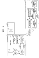
- FIG. 1 is a block diagram illustrating a structure according to a first embodiment of the present invention.
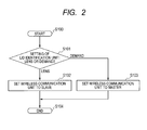
- FIG. 2 is a flowchart illustrating a master/slave setting process in the first embodiment of the present invention.
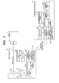
- FIG. 3 is a block diagram illustrating a structure according to a second embodiment of the present invention.
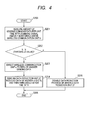
- FIG. 4 is a process flowchart in the second embodiment of the present invention.
- FIG. 5 is a block diagram illustrating a structure according to a third embodiment of the present invention.
- FIG. 6 is a process flowchart in the third embodiment of the present invention.
- FIG. 7 is a block diagram illustrating the modified structure of a commanding apparatus illustrated in FIG. 5 .
- FIG. 8 a block diagram illustrating a structure according to a fourth embodiment of the present invention.
- FIG. 9 is a flowchart illustrating a master/slave setting process in the fourth embodiment of the present invention.
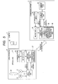
- FIG. 1 is a block diagram illustrating a structure according to a first embodiment of the present invention.
- a television lens (lens apparatus) 2 is detachably attached to a television camera (image pickup apparatus main body or camera main body) 1 which is an image pickup unit, and performs wireless communication with a commanding apparatus 3 which is a zoom demand or a focus demand each serving as an external device.
- An image pickup element 10 is a CCD or a CMOS device.
- a movable optical member 20 is disposed on an optical axis 4 common to the television camera 1 and the television lens 2, and moved in an optical axis direction, to thereby perform zoom and focus adjustments.
- the movable optical member 20 is driven by a motor 21.
- a position of the movable optical member 20 in the optical axis direction is detected by an encoder 22.
- a drive control unit 23 generates a drive signal for driving the motor 21 in response to a command-a (Sig2) from the commanding apparatus 3 and a position signal obtained from the encoder 22.
- Sig2 command-a
- a wireless communication unit-a (first wireless communication unit) 24 is a wireless unit for performing wireless communication through a master/slave communication system, and outputs, as the command-a (Sig2), the command signal received from the commanding apparatus 3, to the drive control unit 23.
- the drive control unit 23 outputs an answer-a (Sig3), which is an answer signal corresponding to the position information of the movable optical member, to the wireless communication unit-a 24.
- the wireless communication unit-a 24 sends the answer-a (Sig3) to the commanding apparatus 3.
- a lens/demand identification unit-a 25 outputs, to a master/slave set unit-a (first set unit) 26, a signal indicating that an apparatus to which the wireless communication unit-a 24 is attached is the lens apparatus 2.
- the master/slave set unit-a 26 sets the wireless communication unit-a 24 as a slave.
- the movable optical member 20 includes a magnification-varying lens unit which moves during zooming, a focus lens unit which moves during focusing, a stop, and an extender (focal-length-varying optical system which varies a focal length by its insertion to or removal from an optical path) .
- a command direct unit 30 includes thumb rings and switches in a case of the zoom demand or knobs and switches in a case of the focus demand.
- a command signal from the command direct unit 30 is input to a command control unit 31, subjected to arithmetic processing and command processing, and then output as a command-b (Sig1) to a wireless communication unit-b 32.
- the wireless communication unit-b (second wireless communication unit) 32 is a wireless unit for performing wireless communication through the master/slave communication system.
- the wireless communication unit-b 32 sends a send signal to the wireless communication unit-a 24 of the television lens 2.
- An answer signal from the wireless communication unit-a 24 of the television lens 2 is received by the wireless communication unit-b 32 and sent as an answer-b (Sig4) to the command control unit 31.
- a lens/demand identification unit-b 33 outputs, to a master/slave set unit-b (second set unit) 34, a signal indicating that an apparatus to which the wireless communication unit-b 32 is attached is the commanding apparatus 3.
- the master/slave set unit-b 34 sets the wireless communication unit-b 32 as a master.
- the command signal generated by operating the command direct unit 30 of the commanding apparatus 3 is transferred to the drive control unit 23 through the command control unit 31, the wireless communication unit-b 32, and the wireless communication unit-a 24, to thereby drive the movable optical member 20.
- the drive control unit 23 generates the position signal of the movable optical member 20 in response to a pulse signal from the encoder 22.
- the position signal and signals indicating various states of the television lens 2 are each transferred as the answer signal to the command control unit 31 through the wireless communication unit-a 24 and the wireless communication unit-b 32.
- FIG. 2 is a flowchart illustrating a master/slave setting flow for determining which of the wireless communication unit-a 24 and the wireless communication unit-b 32 is set as the master or the slave.
- the master/slave setting flow illustrated in FIG. 2 is executed before the wireless communication unit-a 24 and the wireless communication unit-b 32 are brought into a connectable state, and executed to define an initial state of the wireless communication unit-a 24 and an initial state of the wireless communication unit-b 32 at the time of initialization including power-on or forced reset processing.
- Step S101 the lens/demand identification unit-a 25 and the lens/demand identification unit-b 33 determine whether setting is to be made for the wireless communication unit-a provided in the television lens 2 or the wireless communication unit-b provided in the commanding apparatus 3.
- Step S102 the processing proceeds to Step S102.
- Step S103 the wireless communication unit is set as the slave, and the processing proceeds to Step S104.
- Step S103 the wireless communication unit is set as the master, and the processing proceeds to Step S104.
- the wireless communication unit-a 24 of the television lens 2 is set as the slave and the wireless communication unit-b 32 of the commanding apparatus 3 is set as the master.
- the wireless communication unit-a 24 and the wireless communication unit-b 32 are set as the slave and the master, respectively, based on the master/slave setting flow illustrated in FIG. 2 , the wireless communication between the television lens 2 and the commanding apparatus 3 is activated.
- the wireless communication unit-a 24 of the lens apparatus side may be set as the slave and the wireless communication unit-b 32 of the commanding apparatus side may be set as the master. Therefore, the command signal may be sent from the commanding apparatus 3 to the lens apparatus 2, immediately after the time of initialization processing including power-on or forced reset processing, and hence a lens system which is excellent in responsiveness may be provided.
- the lens/demand identification unit-a 25 and the lens/demand identification unit-b 33 illustrated in FIG. 1 may be realized as setting switches or may be set in advance by a computer.
- reduction of signal amount (data amount) between the wireless communication unit on the lens apparatus side and that on the commanding apparatus side is not described in the first embodiment. However, it is preferable to perform the reduction of signal amount.
- the reduction of signal amount (reduction of part of data) is mainly performed for signals (data, response signals) sent from the lens apparatus side to the commanding apparatus side, so that the reduction of signal amount should not be performed for signals (data, command signals) sent from the commanding apparatus side to the lens apparatus side.
- a method of the reduction of signal amount is described in the second and third embodiments.
- FIG. 3 is a block diagram illustrating a structure according to a second embodiment of the present invention.
- the same blocks as the structural blocks in the first embodiment illustrated in FIG. 1 are denoted by the same reference number.
- the blocks denoted by the same reference number may be similarly described as in the first embodiment, and hence the description thereof is omitted.
- FIG. 3 is different from FIG. 1 in that a sending data reduction unit 27 and a command signal amount monitoring unit 35 are further provided in the wireless communication unit-a 24 and the wireless communication unit-b 32, respectively.
- FIG. 4 is a process flowchart illustrating operations of the sending data reduction unit 27 and the command signal amount monitoring unit 35 in the structural block diagram of FIG. 3 .
- Step S200 the processing starts in Step S200.
- a data amount X for example, the number of bytes, of a sending command signal sent from the wireless communication unit-b 32 to the wireless communication unit-a 24 per unit time is monitored (measured) by the command signal amount monitoring unit 35, and the processing proceeds to Step S202.
- Step S202 the data amount X is compared with a predetermined threshold value N which is set in advance. When X>N, the processing proceeds to Step S203. When X ⁇ N, the processing proceeds to Step S205.
- Step S203 the processing in a case where a signal amount of the command-b (Sig1) from the commanding apparatus 3 is large (X>N) is performed.
- the wireless communication unit-a 24 on the television lens 2 side is directed to cause the sending data reduction unit 27 to activate data reduction, and then the processing proceeds to S204.
- Step S204 the answer-a (Sig3) of the answer signal is subjected to data reduction processing by the sending data reduction unit 27 as directed, and wirelessly sent to the commanding apparatus 3 side.
- Step S206 the data reduction processing by the sending data reduction unit 27 is disabled, and the processing proceeds to Step S206.
- the data reduction processing performed by the sending data reduction unit 27 is a processing of performing reduction of the answer-a (Sig3) so that the data amount of the answer-a (Sig3), which is the position signal of the movable optical member and sent at regular intervals from the drive control unit 23 included in the television lens 2, is 1/m (m: arbitrary positive integer) of a data amount before reduction, and then sending the answer-a from the wireless communication unit-a 24 to the wireless communication unit-b 32 of the commanding apparatus 3.
- the amount of command data sent from the commanding apparatus 3 to the television lens 2 per unit time is constantly monitored by the command signal amount monitoring unit 35 of the commanding apparatus 3.
- the processing of reducing the amount of answer data sent from the television lens 2 to the commanding apparatus 3 is performed by the sending data reduction unit 27 included in the television lens 2.
- a total communication amount between the wireless communication units per unit time is reduced, to thereby reduce a communication load.
- the command signal amount monitoring unit 35 is included in the wireless communication unit-b 32 of the commanding apparatus 3.
- the command signal amount monitoring unit does not necessarily monitor the actual amount of command signal. That is, the command signal amount monitoring unit can be a unit which monitors (determines) whether the wireless communication between the lens (lens apparatus) and the demand (commanding apparatus) is performed with digital signals, and also whether the communication in the demand between the operation unit by an user and the wireless communication unit (signal sending/receiving unit) which wirelessly communicates with the lens apparatus is performed through digital communication or analog communication. In the latter case (in which the communication between the operation unit and the wireless communication unit is performed through digital signal), the signal amount of digital communication is larger than that of analog communication, so that the answer data (response signal) amount is reduced.
- the threshold value N for the command signal amount monitoring unit 35 may be arbitrarily adjusted.
- a set switch may be provided to determine in advance whether or not the data reduction processing is always performed by the sending data reduction unit 27 without the comparison with the threshold value N.
- the positive integer m of 1/m which is a reduction amount of the sending data reduction unit 27, may be adjusted in proportion to the data amount X.
- FIG. 5 is a block diagram illustrating a structure according to a third embodiment of the present invention.
- the same blocks as the structural blocks in the second embodiment illustrated in FIG. 3 are denoted by the same reference number.
- the blocks denoted by the same reference number may be similarly described as in the first and second embodiments, and hence the description thereof is omitted.
- FIG. 5 is different from FIG. 3 in that a reception data restoration unit 36 is further provided in the wireless communication unit-b 32 of the commanding apparatus 3.
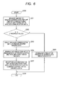
- FIG. 6 is a process flowchart illustrating operations of the sending data reduction unit 27, the command signal amount monitoring unit 35, and the reception data restoration unit 36 in the structural block diagram of FIG. 5 .
- the same processings as in the flowchart of FIG. 4 are denoted by the same reference number.
- the processings denoted by the same reference number may be similarly described as in the second embodiment, and hence the description thereof is omitted.
- FIG. 6 is different from FIG. 4 in that Step S207 corresponding to reception data restoration processing is added to the flowchart of FIG. 6 .
- the answer data which is reduced by the sending data reduction unit 27 and sent from the television lens 2 to the commanding apparatus 3 is restored to original data by the reception data restoration unit 36 included in the commanding apparatus 3.
- the data amount of the answer-a (Sig3) which is the position signal of the movable optical member and sent at regular intervals, is reduced to 1/m (m: arbitrary positive integer) by the sending data reduction unit 27 to obtain reduction data.
- the reduction data is increased by m times by interpolation by the reception data restoration unit 36 and then sent as the answer-b (Sig4) to the command control unit 31.
- the command control unit 31 of the commanding apparatus 3 which is the demand, even when the amount of a command signal sent from the commanding apparatus 3 to the television lens 2 is increased, the signal amount of the answer-b (Sig4) does not change.
- the amount of data processed in an existing commanding apparatus may be provided with compatibility.
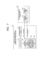
- FIG. 7 illustrates a commanding apparatus side structure in a case where a wireless apparatus 3a located on a commanding apparatus side is connected to a conventional demand (existing commanding apparatus 3b) having no wireless function so as to provide a wireless function to the conventional demand, which is the same structure as in FIG. 5 .
- the sending data reduction unit 27 and the reception data restoration unit 36 are provided, and hence the wireless communication of the existing demand may be achieved and a lens system which is excellent in responsiveness may be realized.
- the signal which is reduced by the sending data reduction unit 27 and restored by the reception data restoration unit 36 is the signal (data) indicating a position or a state of a member (optical system, optical member) whose position or state varies continuously, and is more specifically a response signal (answer signal, answer data) sent from the lens (lens apparatus) to the demand (commanding apparatus).
- the member whose position or state varies continuously is not a member which can take only two or three values in position or state, but a member which can take at least ten or more values in position or state within whole movable area (state varying area).
- the member whose position or state varies continuously includes particularly a magnification-varying lens unit (zooming lens unit) which moves during zooming, a focus lens unit which moves during focusing, and a stop which moves (radially as perpendicularly to the optical axis) for adjustment of brightness as like.
- a position of the magnification-varying lens unit may be its position obviously, or may be substituted by a focal length of the whole lens system (whole lens apparatus system).
- the position of the focus lens unit (focus position) can be substituted by an object distance (distance between the lens apparatus and an object).
- a position or a state of a member whose position or state varies discontinuously can be exemplified by a position of an extender optical unit which is an optical unit including one or more optical units which can be inserted to and removed from its optical axis (a state whether or not the extender optical unit is positioned on its optical axis), an ON/OFF state of a return switch having a function for changing an image to be displayed on a view finder and other functions, and an ON/OFF state of a VTR (Video Tape Recorder) switch for determining whether or not a video-recording is performed by a camera apparatus on which the lens apparatus is mounted.
- a position of an extender optical unit which is an optical unit including one or more optical units which can be inserted to and removed from its optical axis (a state whether or not the extender optical unit is positioned on its optical axis)
- an ON/OFF state of a return switch having a function for changing an image to be displayed on a view finder and other functions
- the member whose position or state varies discontinuously be a member which can take only two to five values in position or state, such as a switch which has only two positions and an extender optical unit which can dispose (switch to another extender) three optical elements (one or two optical elements may be applicable as well) different from each other in focal length (magnification) as an optical element to be disposed in optical axis in addition to a state in which no optical element having optical power is disposed on its optical axis .
- the extender can take four (or less) positions (or states). So, according to the definition described above in the present invention, the switch and the extender each are regarded as the member whose position or stated varies discontinuously.
- the wireless communication is performed with data in which a part of date of the member whose position or state varies continuously is deleted whereas the reduction of date is not performed for the data of the member whose position or state varies discontinuously.
- a part of answer data (response signals) sent from the lens apparatus to the demand that is, a part of the signal for informing the demand of the current position or the current state in response to a command from the demand, is deleted.
- the deletion (reduction) of a part of data (signals) may be performed according to a determination of demand (by a determination unit included in the lens apparatus) with which the lens apparatus is communicating. Or, the deletion (reduction) may be performed according to a command sent from a command unit included in the demand to the lens apparatus to reduce data.
- the amount of command data sent from the commanding apparatus 3 to the television lens 2 is detected, and when the amount of command data is larger than a threshold value which is set in advance, the amount of answer data sent from the television lens 2 to the commanding apparatus 3 is reduced. In this manner, even in cases of not only an analog type demand but also a digital type demand of which the amount of command data is large, a lens system which is excellent in responsiveness may be provided.
- the output command signal Sig1 of the existing command value 3b can be an analog signal or a digital command signal.
- the amount of information is small in the case in which the output command signal Sig1 is the analog signal, whereas the amount of information is large in the case in which the output command signal Sig1 is the digital command signal.
- the wireless communication apparatus 3a on the command apparatus side may make the sending data reduction unit 27 and the reception data restoration unit 36 disabled in response to the detection of the communication with analog type demand.
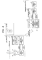
- FIG. 8 is a block diagram illustrating a structure according to a fourth embodiment of the present invention.
- the same blocks as the structural blocks in the first embodiment illustrated in FIG. 1 are denoted by the same reference number.
- the blocks denoted by the same reference number may be similarly described as in the first embodiment, and hence the description thereof is omitted.
- FIG. 8 is different from FIG. 1 in that a command change detection unit 37 is further provided in the wireless communication unit-b 32.
- FIG. 9 is a flowchart illustrating a master/slave setting process flow for the structural block diagram of FIG. 8 and a description is made thereto.
- the processing starts in Step S300, and the processing proceeds to Step S301.
- Step S301 it is detected, by the command change detection unit 37, whether or not the command value of the commanding apparatus 3 is changed (whether or not command direct unit 30 is operated) within a fixed time period. Subsequently, the processing proceeds to Step S302 which is determination processing.
- the command change detection unit 37 detects that the command value is not changed within the fixed time period, the processing proceeds to Step S303.
- the command value is changed, the processing proceeds to Step S304.
- Step S303 the wireless communication unit-a 24 is set as the master while the wireless communication unit-b 32 is set as the slave, and the processing proceeds to Step S305.
- Step S304 the wireless communication unit-a 24 is set as the slave while the wireless communication unit-b 32 is set as the master, and the processing proceeds to Step S305. The processing ends in Step S305.
- the wireless communication unit-a 24 when the command value sent from the commanding apparatus 3 to the television lens 2 is not changed within a fixed time period, the wireless communication unit-a 24 is set as the master and the wireless communication unit-b 32 is set as the slave. In addition, when the command value is changed, the wireless communication unit-a 24 is set as the slave and the wireless communication unit-b 32 is set as the master.
- the processing described above is performed, a lens system which is excellent in responsiveness may be provided while the commanding apparatus such as the demand is operated by an operator.
- the wireless communication unit-b 32 is set as the slave, and hence the electric consumption of the commanding apparatus 3 may be reduced.
- the commanding apparatus 3 is battery-operated, a lens system which is excellent in responsiveness and low in electric consumption may be provided.
- This embodiment relates to an image pickup system which includes: the image pickup apparatus main body (television camera) 1 having the image pickup device 10; and the lens system (having lens apparatus 2 and commanding apparatus 3) according to any one of Embodiments 1 to 4.
- the lens apparatus 2 included in the lens system (having lens apparatus 2 and commanding apparatus 3) is detachably attachable to the image pickup apparatus main body 1.
- an image pickup system which is excellent in responsiveness and low in electric consumption may be realized.
- the lens apparatus 2 includes the movable optical member 20, the wireless communication unit 24 for performing wireless communication with the commanding apparatus 3 for generating a command signal to drive the movable optical member 20 through the master/slave communication system, and the set units (25 and 26) for setting the wireless communication unit 24 as the slave when the lens apparatus 2 is initialized.
- the lens apparatus 2 is detachably attachable to the image pickup apparatus main body 1 having the image pickup device 10.
- the lens apparatus 2 which is excellent in responsiveness and low in electric consumption may be realized.
- This embodiment relates to the commanding apparatus 3 for outputting, to the lens apparatus 2 including the movable optical member 20, a command signal to drive the movable optical member 20.
- the commanding apparatus 3 includes: the wireless communication unit 32 for performing wireless communication with the wireless communication unit 24 included in the lens apparatus 2 through the master/slave communication system; and the set units (33 and 34) for setting the wireless communication unit 32 as the master when the commanding apparatus 3 is initialized.
- an image pickup system which is excellent in responsiveness and low in electric consumption may be realized.
- the lens system includes: a lens apparatus including a member whose position or state varies continuously; and a commanding apparatus outputting a command signal to the member, wherein the lens apparatus includes a first wireless communication unit performing wireless communication through a master/slave communication and a first set unit setting the first wireless communication as slave when the lens apparatus is initialized, the lens apparatus sends to the commanding apparatus an answer on the member whose position or state varies continuously; the commanding apparatus includes a second wireless communication unit performing wireless communication through the master/slave communication and communicates with the first wireless unit and a second set unit setting the second wireless communication unit as master when the commanding apparatus is initialized, and the lens apparatus includes a data reduction unit deleting a part of the answer data sent from the first to the second wireless unit.
Landscapes
- Engineering & Computer Science (AREA)
- Physics & Mathematics (AREA)
- Multimedia (AREA)
- Signal Processing (AREA)
- General Engineering & Computer Science (AREA)
- General Physics & Mathematics (AREA)
- Optics & Photonics (AREA)
- Studio Devices (AREA)
- Lens Barrels (AREA)
- Structure And Mechanism Of Cameras (AREA)
- Exposure Control For Cameras (AREA)
Abstract
The lens system includes: a lens apparatus including a member whose position or state varies continuously; and a commanding apparatus outputting a command signal to the member, wherein the lens apparatus includes a first wireless communication unit performing wireless communication through a master/slave communication and a first set unit setting the first wireless communication as slave when the lens apparatus is initialized, the lens apparatus sends to the commanding apparatus an answer on the member whose position or state varies continuously; the commanding apparatus includes a second wireless communication unit performing wireless communication through the master/slave communication and communicates with the first wireless unit and a second set unit setting the second wireless communication unit as master when the commanding apparatus is initialized, and the lens apparatus includes a data reduction unit deleting a part of the answer data sent from the first to the second wireless unit.
Description
- The present invention relates to a lens system for electrically driving a movable optical member in response to a drive command from a commanding apparatus, and more particularly, to a broadcasting television lens system.
- Heretofore, a television lens used for television broadcast is detachably attachable to a television camera. The television lens includes multiple movable optical members for variable adjustments of zooming and focusing as like. The movable optical members may be electrically driven in response to commands from a commanding apparatus. There are exemplified, as the commanding apparatus, a zoom demand for variable adjustment of zooming and a focus demand for variable adjustment of focusing. The television lens is usually connected to the zoom demand and the focus demand through cables. A structure of the conventional television lens described above is illustrated in
FIG. 6 included in Japanese Patent Application Laid-Open No.H08-334673 - Further, Japanese Patent Application Laid-Open No.
2007-293070 - When a wireless communication function described in Japanese Patent Application Laid-Open No.
2007-293070 2007-293070 - Each of the wireless communication systems is a master/slave communication system. That is, periodic polling from an apparatus side set as a master to an apparatus side set as a slave is performed. Data communication from the master to the slave is performed after activation of the polling. Communication from the slave side to the master side is performed in response to the polling. However, Japanese Patent Application Laid-Open No.
2007-293070 - Japanese Patent Application Laid-Open No.
2002-280925 - In Japanese Patent Application Laid-Open No.
2002-280925 - Consideration is given to a case where a master/slave setting is made for a wireless communication function as in Japanese Patent Application Laid-Open No.
2002-280925 2007-293070 - When the wireless communication function of the commanding apparatus side is set as the slave function, low electric consumption is achieved, and hence the availability of the battery is improved. However, a command signal is sent after polling from the master side which is the lens apparatus, which leads to a problem that responsiveness is deteriorated.
- The commanding apparatus is categorized into two types, namely, an analog demand for sending an analog signal as a command value to the lens apparatus and a digital demand for sending the command value to the lens apparatus through digital communication. When the lens apparatus and the commanding apparatus are wirelessly connected to each other by the wireless communication function, the amount of data sent from the commanding apparatus to the lens apparatus varies between the analog demand and the digital demand. In general, the amount of data in the digital demand is several times larger than the amount of data in the analog demand. Therefore, when the lens apparatus and the commanding apparatus are wirelessly connected to each other by the wireless communication function, there arises a problem that the responsiveness in the digital demand is further deteriorated as compared with the responsiveness in the analog demand.
- The present invention has been made in view of the problems as described above, and it is an object of the present invention to provide a lens system which is excellent in responsiveness in a case where a lens apparatus and a commanding apparatus are wirelessly connected to each other by a wireless communication function. It is another object of the present invention to provide a lens system which is excellent in responsiveness even in a case where any one of an analog demand and a digital demand is used as the commanding apparatus.
- In order to attain the above-mentioned objects, the present invention provides a lens system, including: a lens apparatus including a member whose position or state varies continuously; and a commanding apparatus for outputting a command signal to the member, in which the lens apparatus includes: a first wireless communication unit which can perform wireless communication through a master/slave communication system; and a first set unit for setting the first wireless communication unit as a slave when the lens apparatus is initialized; the lens apparatus sends to the commanding apparatus an answer data on the member whose position or state varies continuously; the commanding apparatus includes: a second wireless communication unit which can perform wireless communication through the master/slave communication system and communicates with the first wireless communication unit; and a second set unit for setting the second wireless communication unit as a master when the commanding apparatus is initialized; and the lens apparatus includes a data reduction unit for deleting a part of the answer data which is sent from the first wireless communication unit to the second wireless communication unit.
- Further features of the present invention will become apparent from the following description of exemplary embodiments with reference to the attached drawings.
- According to the present invention, a wireless communication function of the lens apparatus side is always set as the slave and a wireless communication function of the commanding apparatus side is always set as the master. Therefore, the command signal may be immediately sent from the commanding apparatus to the lens apparatus, and hence a lens system which is excellent in responsiveness may be provided.
- When the amount of command data sent from the commanding apparatus to the lens apparatus is increased, the amount of data to be sent from the wireless communication function of the lens apparatus side to the wireless communication function of the commanding apparatus side is reduced. Therefore, the command data is prevented from being delayed, and hence a lens system which is excellent in responsiveness may be provided even in a case of the digital demand.
- Further features of the present invention will become apparent from the following description of exemplary embodiments with reference to the attached drawings.
-
FIG. 1 is a block diagram illustrating a structure according to a first embodiment of the present invention. -
FIG. 2 is a flowchart illustrating a master/slave setting process in the first embodiment of the present invention. -
FIG. 3 is a block diagram illustrating a structure according to a second embodiment of the present invention. -
FIG. 4 is a process flowchart in the second embodiment of the present invention. -
FIG. 5 is a block diagram illustrating a structure according to a third embodiment of the present invention. -
FIG. 6 is a process flowchart in the third embodiment of the present invention. -
FIG. 7 is a block diagram illustrating the modified structure of a commanding apparatus illustrated inFIG. 5 . -
FIG. 8 a block diagram illustrating a structure according to a fourth embodiment of the present invention. -
FIG. 9 is a flowchart illustrating a master/slave setting process in the fourth embodiment of the present invention. - Hereinafter, embodiments of the present invention are described in detail with reference to the attached drawings.
- First Embodiment
-
FIG. 1 is a block diagram illustrating a structure according to a first embodiment of the present invention. - A television lens (lens apparatus) 2 is detachably attached to a television camera (image pickup apparatus main body or camera main body) 1 which is an image pickup unit, and performs wireless communication with a
commanding apparatus 3 which is a zoom demand or a focus demand each serving as an external device. - An
image pickup element 10 is a CCD or a CMOS device. - An internal structure of the
television lens 2 is described. A movableoptical member 20 is disposed on anoptical axis 4 common to thetelevision camera 1 and thetelevision lens 2, and moved in an optical axis direction, to thereby perform zoom and focus adjustments. The movableoptical member 20 is driven by amotor 21. A position of the movableoptical member 20 in the optical axis direction is detected by anencoder 22. Adrive control unit 23 generates a drive signal for driving themotor 21 in response to a command-a (Sig2) from thecommanding apparatus 3 and a position signal obtained from theencoder 22. A wireless communication unit-a (first wireless communication unit) 24 is a wireless unit for performing wireless communication through a master/slave communication system, and outputs, as the command-a (Sig2), the command signal received from thecommanding apparatus 3, to thedrive control unit 23. Thedrive control unit 23 outputs an answer-a (Sig3), which is an answer signal corresponding to the position information of the movable optical member, to the wireless communication unit-a 24. Then, the wireless communication unit-a 24 sends the answer-a (Sig3) to thecommanding apparatus 3. A lens/demand identification unit-a 25 outputs, to a master/slave set unit-a (first set unit) 26, a signal indicating that an apparatus to which the wireless communication unit-a 24 is attached is thelens apparatus 2. The master/slave set unit-a 26 sets the wireless communication unit-a 24 as a slave. - Here, the movable
optical member 20 includes a magnification-varying lens unit which moves during zooming, a focus lens unit which moves during focusing, a stop, and an extender (focal-length-varying optical system which varies a focal length by its insertion to or removal from an optical path) . - A structure of the
commanding apparatus 3 is described. A commanddirect unit 30 includes thumb rings and switches in a case of the zoom demand or knobs and switches in a case of the focus demand. A command signal from the commanddirect unit 30 is input to acommand control unit 31, subjected to arithmetic processing and command processing, and then output as a command-b (Sig1) to a wireless communication unit-b 32. The wireless communication unit-b (second wireless communication unit) 32 is a wireless unit for performing wireless communication through the master/slave communication system. The wireless communication unit-b 32 sends a send signal to the wireless communication unit-a 24 of thetelevision lens 2. An answer signal from the wireless communication unit-a 24 of thetelevision lens 2 is received by the wireless communication unit-b 32 and sent as an answer-b (Sig4) to thecommand control unit 31. A lens/demand identification unit-b 33 outputs, to a master/slave set unit-b (second set unit) 34, a signal indicating that an apparatus to which the wireless communication unit-b 32 is attached is thecommanding apparatus 3. The master/slave set unit-b 34 sets the wireless communication unit-b 32 as a master. - During the normal operation using the structure described above, the command signal generated by operating the command
direct unit 30 of thecommanding apparatus 3 is transferred to thedrive control unit 23 through thecommand control unit 31, the wireless communication unit-b 32, and the wireless communication unit-a 24, to thereby drive the movableoptical member 20. In addition, thedrive control unit 23 generates the position signal of the movableoptical member 20 in response to a pulse signal from theencoder 22. The position signal and signals indicating various states of thetelevision lens 2 are each transferred as the answer signal to thecommand control unit 31 through the wireless communication unit-a 24 and the wireless communication unit-b 32. -
FIG. 2 is a flowchart illustrating a master/slave setting flow for determining which of the wireless communication unit-a 24 and the wireless communication unit-b 32 is set as the master or the slave. The master/slave setting flow illustrated inFIG. 2 is executed before the wireless communication unit-a 24 and the wireless communication unit-b 32 are brought into a connectable state, and executed to define an initial state of the wireless communication unit-a 24 and an initial state of the wireless communication unit-b 32 at the time of initialization including power-on or forced reset processing. - In the master/slave setting flow illustrated in
FIG. 2 , the processing starts in Step S100, and proceeds to Step S101. In Step S101, the lens/demand identification unit-a 25 and the lens/demand identification unit-b 33 determine whether setting is to be made for the wireless communication unit-a provided in thetelevision lens 2 or the wireless communication unit-b provided in thecommanding apparatus 3. When the setting is to be made for the wireless communication unit-a provided in thetelevision lens 2, the processing proceeds to Step S102. When the setting is to be made for the wireless communication unit-b provided in thecommanding apparatus 3 which is the demand, the processing proceeds to Step S103. In Step S102, the wireless communication unit is set as the slave, and the processing proceeds to Step S104. In Step S103, the wireless communication unit is set as the master, and the processing proceeds to Step S104. The processing Step ends in Step S104. When the master/slave setting flow illustrated inFIG. 2 is executed, the wireless communication unit-a 24 of thetelevision lens 2 is set as the slave and the wireless communication unit-b 32 of thecommanding apparatus 3 is set as the master. When the wireless communication unit-a 24 and the wireless communication unit-b 32 are set as the slave and the master, respectively, based on the master/slave setting flow illustrated inFIG. 2 , the wireless communication between thetelevision lens 2 and thecommanding apparatus 3 is activated. - As described above, according to the structural block diagram of
FIG. 1 and the master/slave setting flow illustrated inFIG. 2 , the wireless communication unit-a 24 of the lens apparatus side may be set as the slave and the wireless communication unit-b 32 of the commanding apparatus side may be set as the master. Therefore, the command signal may be sent from thecommanding apparatus 3 to thelens apparatus 2, immediately after the time of initialization processing including power-on or forced reset processing, and hence a lens system which is excellent in responsiveness may be provided. - The lens/demand identification unit-a 25 and the lens/demand identification unit-
b 33 illustrated inFIG. 1 may be realized as setting switches or may be set in advance by a computer. - In addition, reduction of signal amount (data amount) between the wireless communication unit on the lens apparatus side and that on the commanding apparatus side is not described in the first embodiment. However, it is preferable to perform the reduction of signal amount. The reduction of signal amount (reduction of part of data) is mainly performed for signals (data, response signals) sent from the lens apparatus side to the commanding apparatus side, so that the reduction of signal amount should not be performed for signals (data, command signals) sent from the commanding apparatus side to the lens apparatus side. A method of the reduction of signal amount is described in the second and third embodiments.
- Second Embodiment
-
FIG. 3 is a block diagram illustrating a structure according to a second embodiment of the present invention. The same blocks as the structural blocks in the first embodiment illustrated inFIG. 1 are denoted by the same reference number. The blocks denoted by the same reference number may be similarly described as in the first embodiment, and hence the description thereof is omitted.FIG. 3 is different fromFIG. 1 in that a sendingdata reduction unit 27 and a command signalamount monitoring unit 35 are further provided in the wireless communication unit-a 24 and the wireless communication unit-b 32, respectively. -
FIG. 4 is a process flowchart illustrating operations of the sendingdata reduction unit 27 and the command signalamount monitoring unit 35 in the structural block diagram ofFIG. 3 . - In
FIG. 4 , the processing starts in Step S200. Assume that, before the start of the processing, the master/slave setting flow illustrated inFIG. 2 is completed and normal wireless communication is in a connection state. In Step S201, a data amount X, for example, the number of bytes, of a sending command signal sent from the wireless communication unit-b 32 to the wireless communication unit-a 24 per unit time is monitored (measured) by the command signalamount monitoring unit 35, and the processing proceeds to Step S202. In Step S202, the data amount X is compared with a predetermined threshold value N which is set in advance. When X>N, the processing proceeds to Step S203. When X≤N, the processing proceeds to Step S205. In Step S203, the processing in a case where a signal amount of the command-b (Sig1) from thecommanding apparatus 3 is large (X>N) is performed. First, the wireless communication unit-a 24 on thetelevision lens 2 side is directed to cause the sendingdata reduction unit 27 to activate data reduction, and then the processing proceeds to S204. In Step S204, the answer-a (Sig3) of the answer signal is subjected to data reduction processing by the sendingdata reduction unit 27 as directed, and wirelessly sent to thecommanding apparatus 3 side. Then, the processing proceeds to Step S206. In Step S205, the data reduction processing by the sendingdata reduction unit 27 is disabled, and the processing proceeds to Step S206. The processing ends in Step S206. - The data reduction processing performed by the sending
data reduction unit 27 is a processing of performing reduction of the answer-a (Sig3) so that the data amount of the answer-a (Sig3), which is the position signal of the movable optical member and sent at regular intervals from thedrive control unit 23 included in thetelevision lens 2, is 1/m (m: arbitrary positive integer) of a data amount before reduction, and then sending the answer-a from the wireless communication unit-a 24 to the wireless communication unit-b 32 of thecommanding apparatus 3. - As described above, according to the structural block diagram of
FIG. 3 and the process flow illustrated inFIG. 4 , the amount of command data sent from thecommanding apparatus 3 to thetelevision lens 2 per unit time is constantly monitored by the command signalamount monitoring unit 35 of thecommanding apparatus 3. When the amount of command data per unit time is larger than a threshold value which is set in advance, the processing of reducing the amount of answer data sent from thetelevision lens 2 to thecommanding apparatus 3 is performed by the sendingdata reduction unit 27 included in thetelevision lens 2. In this manner, a total communication amount between the wireless communication units per unit time is reduced, to thereby reduce a communication load. As a result, even in cases of not only an analog type demand but also a digital type demand of which the amount of command data is large, a lens system which is excellently responsive to the command from the commanding apparatus may be provided. - In this embodiment, the command signal
amount monitoring unit 35 is included in the wireless communication unit-b 32 of thecommanding apparatus 3. However, even in a case where the command signalamount monitoring unit 35 can be included in the wireless communication unit-a 24 of thelens apparatus 2, the same function can be obtained. In addition, the command signal amount monitoring unit does not necessarily monitor the actual amount of command signal. That is, the command signal amount monitoring unit can be a unit which monitors (determines) whether the wireless communication between the lens (lens apparatus) and the demand (commanding apparatus) is performed with digital signals, and also whether the communication in the demand between the operation unit by an user and the wireless communication unit (signal sending/receiving unit) which wirelessly communicates with the lens apparatus is performed through digital communication or analog communication. In the latter case (in which the communication between the operation unit and the wireless communication unit is performed through digital signal), the signal amount of digital communication is larger than that of analog communication, so that the answer data (response signal) amount is reduced. - In the description above, the threshold value N for the command signal
amount monitoring unit 35 may be arbitrarily adjusted. Alternatively, a set switch may be provided to determine in advance whether or not the data reduction processing is always performed by the sendingdata reduction unit 27 without the comparison with the threshold value N. - Further, instead of comparing the data amount X with the threshold value N in the command signal
amount monitoring unit 35, the positive integer m of 1/m, which is a reduction amount of the sendingdata reduction unit 27, may be adjusted in proportion to the data amount X. - Third Embodiment
-
FIG. 5 is a block diagram illustrating a structure according to a third embodiment of the present invention.
The same blocks as the structural blocks in the second embodiment illustrated inFIG. 3 are denoted by the same reference number. The blocks denoted by the same reference number may be similarly described as in the first and second embodiments, and hence the description thereof is omitted.FIG. 5 is different fromFIG. 3 in that a receptiondata restoration unit 36 is further provided in the wireless communication unit-b 32 of thecommanding apparatus 3. -
FIG. 6 is a process flowchart illustrating operations of the sendingdata reduction unit 27, the command signalamount monitoring unit 35, and the receptiondata restoration unit 36 in the structural block diagram ofFIG. 5 . The same processings as in the flowchart ofFIG. 4 are denoted by the same reference number. The processings denoted by the same reference number may be similarly described as in the second embodiment, and hence the description thereof is omitted.FIG. 6 is different fromFIG. 4 in that Step S207 corresponding to reception data restoration processing is added to the flowchart ofFIG. 6 . - According to the structural block diagram of
FIG. 5 and the process flow illustrated inFIG. 6 , when the amount of a command signal sent from thecommanding apparatus 3, which is the demand, to thetelevision lens 2 is increased, the answer data which is reduced by the sendingdata reduction unit 27 and sent from thetelevision lens 2 to thecommanding apparatus 3 is restored to original data by the receptiondata restoration unit 36 included in thecommanding apparatus 3. To be specific, the data amount of the answer-a (Sig3), which is the position signal of the movable optical member and sent at regular intervals, is reduced to 1/m (m: arbitrary positive integer) by the sendingdata reduction unit 27 to obtain reduction data. The reduction data is increased by m times by interpolation by the receptiondata restoration unit 36 and then sent as the answer-b (Sig4) to thecommand control unit 31. - Therefore, as viewed from the
command control unit 31 of thecommanding apparatus 3 which is the demand, even when the amount of a command signal sent from thecommanding apparatus 3 to thetelevision lens 2 is increased, the signal amount of the answer-b (Sig4) does not change. Thus, in a structure as illustrated inFIG. 7 in which a wireless apparatus is additionally attached to a commanding apparatus having no wireless function so that control data may be sent and received to and from thetelevision lens 2 through wireless communication, the amount of data processed in an existing commanding apparatus may be provided with compatibility. -
FIG. 7 illustrates a commanding apparatus side structure in a case where awireless apparatus 3a located on a commanding apparatus side is connected to a conventional demand (existingcommanding apparatus 3b) having no wireless function so as to provide a wireless function to the conventional demand, which is the same structure as inFIG. 5 . As described above, the sendingdata reduction unit 27 and the receptiondata restoration unit 36 are provided, and hence the wireless communication of the existing demand may be achieved and a lens system which is excellent in responsiveness may be realized. - Further, the signal which is reduced by the sending
data reduction unit 27 and restored by the receptiondata restoration unit 36 is the signal (data) indicating a position or a state of a member (optical system, optical member) whose position or state varies continuously, and is more specifically a response signal (answer signal, answer data) sent from the lens (lens apparatus) to the demand (commanding apparatus). Here, the member whose position or state varies continuously is not a member which can take only two or three values in position or state, but a member which can take at least ten or more values in position or state within whole movable area (state varying area). The member whose position or state varies continuously includes particularly a magnification-varying lens unit (zooming lens unit) which moves during zooming, a focus lens unit which moves during focusing, and a stop which moves (radially as perpendicularly to the optical axis) for adjustment of brightness as like. Here, a position of the magnification-varying lens unit may be its position obviously, or may be substituted by a focal length of the whole lens system (whole lens apparatus system). The position of the focus lens unit (focus position) can be substituted by an object distance (distance between the lens apparatus and an object). - On the other hand, a position or a state of a member (optical member, electrical switch, mechanical switch) whose position or state varies discontinuously can be exemplified by a position of an extender optical unit which is an optical unit including one or more optical units which can be inserted to and removed from its optical axis (a state whether or not the extender optical unit is positioned on its optical axis), an ON/OFF state of a return switch having a function for changing an image to be displayed on a view finder and other functions, and an ON/OFF state of a VTR (Video Tape Recorder) switch for determining whether or not a video-recording is performed by a camera apparatus on which the lens apparatus is mounted. That is, it is preferable that the member whose position or state varies discontinuously be a member which can take only two to five values in position or state, such as a switch which has only two positions and an extender optical unit which can dispose (switch to another extender) three optical elements (one or two optical elements may be applicable as well) different from each other in focal length (magnification) as an optical element to be disposed in optical axis in addition to a state in which no optical element having optical power is disposed on its optical axis . In this case, the extender can take four (or less) positions (or states). So, according to the definition described above in the present invention, the switch and the extender each are regarded as the member whose position or stated varies discontinuously.
- In the present embodiment, the wireless communication is performed with data in which a part of date of the member whose position or state varies continuously is deleted whereas the reduction of date is not performed for the data of the member whose position or state varies discontinuously. In more detail, among the data of the member whose position or state varies continuously, a part of answer data (response signals) sent from the lens apparatus to the demand, that is, a part of the signal for informing the demand of the current position or the current state in response to a command from the demand, is deleted.
- The deletion (reduction) of a part of data (signals) may be performed according to a determination of demand (by a determination unit included in the lens apparatus) with which the lens apparatus is communicating. Or, the deletion (reduction) may be performed according to a command sent from a command unit included in the demand to the lens apparatus to reduce data.
- As described above, according to the structural block diagrams of
FIGS. 5 and7 and the process flow illustrated inFIG. 6 , the amount of command data sent from thecommanding apparatus 3 to thetelevision lens 2 is detected, and when the amount of command data is larger than a threshold value which is set in advance, the amount of answer data sent from thetelevision lens 2 to thecommanding apparatus 3 is reduced. In this manner, even in cases of not only an analog type demand but also a digital type demand of which the amount of command data is large, a lens system which is excellent in responsiveness may be provided. - Particularly in
FIG. 7 , the output command signal Sig1 of the existingcommand value 3b can be an analog signal or a digital command signal. The amount of information is small in the case in which the output command signal Sig1 is the analog signal, whereas the amount of information is large in the case in which the output command signal Sig1 is the digital command signal. And thewireless communication apparatus 3a on the command apparatus side may make the sendingdata reduction unit 27 and the receptiondata restoration unit 36 disabled in response to the detection of the communication with analog type demand. - Fourth Embodiment
-
FIG. 8 is a block diagram illustrating a structure according to a fourth embodiment of the present invention. The same blocks as the structural blocks in the first embodiment illustrated inFIG. 1 are denoted by the same reference number. The blocks denoted by the same reference number may be similarly described as in the first embodiment, and hence the description thereof is omitted.FIG. 8 is different fromFIG. 1 in that a commandchange detection unit 37 is further provided in the wireless communication unit-b 32. -
FIG. 9 is a flowchart illustrating a master/slave setting process flow for the structural block diagram ofFIG. 8 and a description is made thereto. InFIG. 9 , the processing starts in Step S300, and the processing proceeds to Step S301. In Step S301, it is detected, by the commandchange detection unit 37, whether or not the command value of thecommanding apparatus 3 is changed (whether or not commanddirect unit 30 is operated) within a fixed time period. Subsequently, the processing proceeds to Step S302 which is determination processing. When the commandchange detection unit 37 detects that the command value is not changed within the fixed time period, the processing proceeds to Step S303. When the command value is changed, the processing proceeds to Step S304. In Step S303, the wireless communication unit-a 24 is set as the master while the wireless communication unit-b 32 is set as the slave, and the processing proceeds to Step S305. In contrast, in Step S304, the wireless communication unit-a 24 is set as the slave while the wireless communication unit-b 32 is set as the master, and the processing proceeds to Step S305. The processing ends in Step S305. - As described above, according to the structural block diagram of
FIG. 8 and the process flow illustrated inFIG. 9 , when the command value sent from thecommanding apparatus 3 to thetelevision lens 2 is not changed within a fixed time period, the wireless communication unit-a 24 is set as the master and the wireless communication unit-b 32 is set as the slave. In addition, when the command value is changed, the wireless communication unit-a 24 is set as the slave and the wireless communication unit-b 32 is set as the master. When the processing described above is performed, a lens system which is excellent in responsiveness may be provided while the commanding apparatus such as the demand is operated by an operator. When the demand is not operated by the operator, the wireless communication unit-b 32 is set as the slave, and hence the electric consumption of thecommanding apparatus 3 may be reduced. Thus, when thecommanding apparatus 3 is battery-operated, a lens system which is excellent in responsiveness and low in electric consumption may be provided. - Fifth Embodiment
- This embodiment relates to an image pickup system which includes: the image pickup apparatus main body (television camera) 1 having the
image pickup device 10; and the lens system (havinglens apparatus 2 and commanding apparatus 3) according to any one ofEmbodiments 1 to 4. Thelens apparatus 2 included in the lens system (havinglens apparatus 2 and commanding apparatus 3) is detachably attachable to the image pickup apparatusmain body 1. - According to the structure of this embodiment, an image pickup system which is excellent in responsiveness and low in electric consumption may be realized.
- Sixth Embodiment
- This embodiment relates to the
lens apparatus 2. Thelens apparatus 2 includes the movableoptical member 20, thewireless communication unit 24 for performing wireless communication with thecommanding apparatus 3 for generating a command signal to drive the movableoptical member 20 through the master/slave communication system, and the set units (25 and 26) for setting thewireless communication unit 24 as the slave when thelens apparatus 2 is initialized. Thelens apparatus 2 is detachably attachable to the image pickup apparatusmain body 1 having theimage pickup device 10. - With the structure according to this embodiment, the
lens apparatus 2 which is excellent in responsiveness and low in electric consumption may be realized. - Seventh Embodiment
- This embodiment relates to the
commanding apparatus 3 for outputting, to thelens apparatus 2 including the movableoptical member 20, a command signal to drive the movableoptical member 20. Thecommanding apparatus 3 includes: thewireless communication unit 32 for performing wireless communication with thewireless communication unit 24 included in thelens apparatus 2 through the master/slave communication system; and the set units (33 and 34) for setting thewireless communication unit 32 as the master when thecommanding apparatus 3 is initialized. - With the structure according to this embodiment, an image pickup system which is excellent in responsiveness and low in electric consumption may be realized.
- While the present invention has been described with reference to exemplary embodiments, it is to be understood that the invention is not limited to the disclosed exemplary embodiments. The scope of the following claims is to be accorded the broadest interpretation so as to encompass all such modifications and equivalent structures and functions. The lens system includes: a lens apparatus including a member whose position or state varies continuously; and a commanding apparatus outputting a command signal to the member, wherein the lens apparatus includes a first wireless communication unit performing wireless communication through a master/slave communication and a first set unit setting the first wireless communication as slave when the lens apparatus is initialized, the lens apparatus sends to the commanding apparatus an answer on the member whose position or state varies continuously; the commanding apparatus includes a second wireless communication unit performing wireless communication through the master/slave communication and communicates with the first wireless unit and a second set unit setting the second wireless communication unit as master when the commanding apparatus is initialized, and the lens apparatus includes a data reduction unit deleting a part of the answer data sent from the first to the second wireless unit.
Claims (10)
- A lens system, comprising:a lens apparatus including a member whose position or state varies continuously; anda commanding apparatus for outputting a command signal to the member,wherein:the lens apparatus includes:a first wireless communication unit which can perform wireless communication through a master/slave communication system; anda first set unit for setting the first wireless communication unit as a slave when the lens apparatus is initialized;the lens apparatus sends to the commanding apparatus an answer data on the member whose position or state varies continuously;the commanding apparatus includes:a second wireless communication unit which can perform wireless communication through the master/slave communication system and communicates with the first wireless communication unit; anda second set unit for setting the second wireless communication unit as a master when the commanding apparatus is initialized; andthe lens apparatus includes a data reduction unit for deleting a part of the answer data which is sent from the first wireless communication unit to the second wireless communication unit.
- A lens system according to claim 1, wherein the data reduction unit deletes a part of a signal indicative of a position or a state of the member whose position or state varies continuously among the answer data which is sent from the first wireless communication unit to the second wireless communication unit.
- A lens system according to claim 1, wherein the lens apparatus comprises a member whose position or state varies discontinuously, and the data reduction unit does not reduce an answer data on a position or a state of the member whose position or state varies discontinuously.
- A lens system according to claim 1, wherein the data reduction unit performs data reduction so that the reduced amount of data is 1/m, where m is an arbitrary positive integer, of the answer data of the member whose position or state varies discontinuously.
- A lens system according to claim 1, wherein the commanding apparatus further comprises a data restoration unit for restoring the reduced amount of data.
- A lens system according to claim 1, wherein the data reduction unit reduces the amount of data associated with one of a zoom position, a focus position, and an iris position.
- A lens system according to claim 1, wherein:the commanding apparatus further comprises a command change detection unit for detecting whether or not the command signal is changed within a fixed time period; andwhen the command signal is not changed within the fixed time period, the first set unit sets the first wireless communication unit as the master and the second set unit sets the second wireless communication unit as the slave.
- An image pickup system, comprising:an image pickup apparatus main body including an image pickup device; andthe lens system according to claim 1,wherein the lens apparatus is detachably attachable to the image pickup apparatus main body.
- A lens apparatus detachably attachable to an image pickup apparatus main body including an image pickup device, comprising:a member whose position or state varies continuously;a first wireless communication unit which can perform wireless communication with a commanding apparatus for outputting a command signal to the member whose position or state varies continuously through a master/slave communication system, and send to the commanding apparatus an answer data on the position or the state of the member whose position or state varies continuously; anda data reduction unit which deletes a part of the answer data which is sent from the first wireless communication unit to the commanding unit.
- A commanding apparatus for outputting, to a lens apparatus including a member whose position or state varies continuously, a command signal for the member whose position or state varies continuously, comprising:a second wireless communication unit for performing wireless communication with a first wireless communication unit included in the lens apparatus, through a master/slave communication system;a set unit for setting the second wireless communication unit as a master when the commanding apparatus is initialized; anda commanding unit which output a command, to a reduction unit of the lens apparatus, to reduce an amount of data to be sent from the first wireless communication unit to the second wireless communication unit.
Applications Claiming Priority (1)
| Application Number | Priority Date | Filing Date | Title |
|---|---|---|---|
| JP2009298394 | 2009-12-28 |
Publications (1)
| Publication Number | Publication Date |
|---|---|
| EP2343585A1 true EP2343585A1 (en) | 2011-07-13 |
Family
ID=43629635
Family Applications (1)
| Application Number | Title | Priority Date | Filing Date |
|---|---|---|---|
| EP10196717A Withdrawn EP2343585A1 (en) | 2009-12-28 | 2010-12-23 | Lens system |
Country Status (3)
| Country | Link |
|---|---|
| US (1) | US8885087B2 (en) |
| EP (1) | EP2343585A1 (en) |
| JP (1) | JP5704915B2 (en) |
Families Citing this family (5)
| Publication number | Priority date | Publication date | Assignee | Title |
|---|---|---|---|---|
| JP5865026B2 (en) * | 2011-11-16 | 2016-02-17 | キヤノン株式会社 | Lens system and photographing system having the same |
| US20140210989A1 (en) * | 2012-06-01 | 2014-07-31 | Mark S. Olsson | Systems and methods involving a smart cable storage drum and network node for transmission of data |
| US10079968B2 (en) | 2012-12-01 | 2018-09-18 | Qualcomm Incorporated | Camera having additional functionality based on connectivity with a host device |
| JP2017151477A (en) * | 2017-05-25 | 2017-08-31 | 株式会社ニコン | Lens barrel and camera system |
| US10979616B2 (en) * | 2018-11-29 | 2021-04-13 | Sony Corporation | Wireless communication between a lens assembly and a camera |
Citations (5)
| Publication number | Priority date | Publication date | Assignee | Title |
|---|---|---|---|---|
| JPH08334673A (en) | 1995-06-07 | 1996-12-17 | Canon Inc | TV lens zoom adjustment device |
| JP2002280925A (en) | 2001-03-19 | 2002-09-27 | Canon Inc | Wireless communication device, storage medium, and program |
| US20040150724A1 (en) * | 2003-01-29 | 2004-08-05 | Nikon Corporation | Digital camera and digital camera system |
| US20070254640A1 (en) * | 2006-04-27 | 2007-11-01 | Bliss Stephen J | Remote control and viewfinder for mobile camera phone |
| JP2007293070A (en) | 2006-04-26 | 2007-11-08 | Canon Inc | Lens system |
Family Cites Families (9)
| Publication number | Priority date | Publication date | Assignee | Title |
|---|---|---|---|---|
| JP3754776B2 (en) | 1996-11-29 | 2006-03-15 | キヤノン株式会社 | Imaging device |
| US6674955B2 (en) * | 1997-04-12 | 2004-01-06 | Sony Corporation | Editing device and editing method |
| JPH11125860A (en) * | 1997-10-22 | 1999-05-11 | Canon Inc | Interchangeable lens system, camera, lens unit and control method |
| US7565680B1 (en) * | 2000-06-30 | 2009-07-21 | Comcast Ip Holdings I, Llc | Advanced set top terminal having a video call feature |
| JP2005292187A (en) * | 2004-03-31 | 2005-10-20 | Fuji Photo Film Co Ltd | Single lens reflex camera |
| JP2006238020A (en) | 2005-02-24 | 2006-09-07 | Olympus Corp | Digital camera system and digital camera |
| JP2007129433A (en) * | 2005-11-02 | 2007-05-24 | Fujifilm Corp | Digital camera |
| JP4315153B2 (en) * | 2005-12-27 | 2009-08-19 | 日本ビクター株式会社 | Video camera |
| JP2008310095A (en) * | 2007-06-15 | 2008-12-25 | Canon Inc | Lens system |
-
2010
- 2010-12-20 US US12/973,027 patent/US8885087B2/en not_active Expired - Fee Related
- 2010-12-23 EP EP10196717A patent/EP2343585A1/en not_active Withdrawn
- 2010-12-28 JP JP2010293875A patent/JP5704915B2/en not_active Expired - Fee Related
Patent Citations (5)
| Publication number | Priority date | Publication date | Assignee | Title |
|---|---|---|---|---|
| JPH08334673A (en) | 1995-06-07 | 1996-12-17 | Canon Inc | TV lens zoom adjustment device |
| JP2002280925A (en) | 2001-03-19 | 2002-09-27 | Canon Inc | Wireless communication device, storage medium, and program |
| US20040150724A1 (en) * | 2003-01-29 | 2004-08-05 | Nikon Corporation | Digital camera and digital camera system |
| JP2007293070A (en) | 2006-04-26 | 2007-11-08 | Canon Inc | Lens system |
| US20070254640A1 (en) * | 2006-04-27 | 2007-11-01 | Bliss Stephen J | Remote control and viewfinder for mobile camera phone |
Also Published As
| Publication number | Publication date |
|---|---|
| US20110157461A1 (en) | 2011-06-30 |
| JP2011155643A (en) | 2011-08-11 |
| US8885087B2 (en) | 2014-11-11 |
| JP5704915B2 (en) | 2015-04-22 |
Similar Documents
| Publication | Publication Date | Title |
|---|---|---|
| US12395730B2 (en) | Accessory apparatus and imaging apparatus | |
| US11892754B2 (en) | Camera, interchangeable lens apparatus, adapter apparatus, control method, and storage medium | |
| EP2448248B1 (en) | Imaging apparatus and accessory, and method and system of the same | |
| US11006031B2 (en) | Accessory device, camera, storage medium, and camera system in which communication is performed via data and notification channels and employs differences in voltage level for the notification channel during a period in which data is received | |
| US20180352142A1 (en) | Image-capturing apparatus, accessory apparatus and control method therefor | |
| EP2343585A1 (en) | Lens system | |
| US10962863B2 (en) | Interchangeable lens, method of operating interchangeable lens, program, lens system, and camera system | |
| US12015847B2 (en) | Image processing apparatus for changing a priority category for object detection, image pickup apparatus, image processing method, and storage medium | |
| US10911659B2 (en) | Accessory device, camera, and storage medium | |
| US11500438B2 (en) | Electronic apparatus and method for controlling the same | |
| US10178297B2 (en) | Accessory apparatus, image-capturing apparatus, control method and storage medium storing control program | |
| US7511903B2 (en) | Lens apparatus | |
| JP6046924B2 (en) | LENS SYSTEM, IMAGING SYSTEM, AND LENS SYSTEM DRIVE CONTROL METHOD | |
| JP2018205721A (en) | Accessory device, camera and communication control program | |
| US7742694B2 (en) | Optical apparatus with aperture controller | |
| EP3570105B1 (en) | Accessory apparatus, camera system having the same, and program | |
| JP5544116B2 (en) | Lens position control device for electronic endoscope | |
| EP1377043A2 (en) | Image signal recording system and optical device | |
| EP4391567A1 (en) | Control apparatus, image capturing apparatus, control method, and program | |
| JP2010041399A (en) | Imaging device and its control method | |
| JP2005043714A (en) | Lens controller |
Legal Events
| Date | Code | Title | Description |
|---|---|---|---|
| PUAI | Public reference made under article 153(3) epc to a published international application that has entered the european phase |
Free format text: ORIGINAL CODE: 0009012 |
|
| AK | Designated contracting states |
Kind code of ref document: A1 Designated state(s): AL AT BE BG CH CY CZ DE DK EE ES FI FR GB GR HR HU IE IS IT LI LT LU LV MC MK MT NL NO PL PT RO RS SE SI SK SM TR |
|
| AX | Request for extension of the european patent |
Extension state: BA ME |
|
| 17P | Request for examination filed |
Effective date: 20120113 |
|
| 17Q | First examination report despatched |
Effective date: 20180809 |
|
| STAA | Information on the status of an ep patent application or granted ep patent |
Free format text: STATUS: THE APPLICATION HAS BEEN WITHDRAWN |
|
| 18W | Application withdrawn |
Effective date: 20200922 |