EP2343430A1 - Installation de porte de garage avec actionneur et chariot mobile - Google Patents
Installation de porte de garage avec actionneur et chariot mobile Download PDFInfo
- Publication number
- EP2343430A1 EP2343430A1 EP11150543A EP11150543A EP2343430A1 EP 2343430 A1 EP2343430 A1 EP 2343430A1 EP 11150543 A EP11150543 A EP 11150543A EP 11150543 A EP11150543 A EP 11150543A EP 2343430 A1 EP2343430 A1 EP 2343430A1
- Authority
- EP
- European Patent Office
- Prior art keywords
- carriage
- garage door
- nose
- holding device
- installation according
- Prior art date
- Legal status (The legal status is an assumption and is not a legal conclusion. Google has not performed a legal analysis and makes no representation as to the accuracy of the status listed.)
- Granted
Links
Images


Classifications
-
- E—FIXED CONSTRUCTIONS
- E05—LOCKS; KEYS; WINDOW OR DOOR FITTINGS; SAFES
- E05F—DEVICES FOR MOVING WINGS INTO OPEN OR CLOSED POSITION; CHECKS FOR WINGS; WING FITTINGS NOT OTHERWISE PROVIDED FOR, CONCERNED WITH THE FUNCTIONING OF THE WING
- E05F15/00—Power-operated mechanisms for wings
- E05F15/60—Power-operated mechanisms for wings using electrical actuators
- E05F15/603—Power-operated mechanisms for wings using electrical actuators using rotary electromotors
- E05F15/665—Power-operated mechanisms for wings using electrical actuators using rotary electromotors for vertically-sliding wings
- E05F15/668—Power-operated mechanisms for wings using electrical actuators using rotary electromotors for vertically-sliding wings for overhead wings
- E05F15/681—Power-operated mechanisms for wings using electrical actuators using rotary electromotors for vertically-sliding wings for overhead wings operated by flexible elongated pulling elements, e.g. belts
-
- E—FIXED CONSTRUCTIONS
- E05—LOCKS; KEYS; WINDOW OR DOOR FITTINGS; SAFES
- E05F—DEVICES FOR MOVING WINGS INTO OPEN OR CLOSED POSITION; CHECKS FOR WINGS; WING FITTINGS NOT OTHERWISE PROVIDED FOR, CONCERNED WITH THE FUNCTIONING OF THE WING
- E05F15/00—Power-operated mechanisms for wings
- E05F15/60—Power-operated mechanisms for wings using electrical actuators
- E05F15/603—Power-operated mechanisms for wings using electrical actuators using rotary electromotors
- E05F15/665—Power-operated mechanisms for wings using electrical actuators using rotary electromotors for vertically-sliding wings
- E05F15/668—Power-operated mechanisms for wings using electrical actuators using rotary electromotors for vertically-sliding wings for overhead wings
-
- E—FIXED CONSTRUCTIONS
- E05—LOCKS; KEYS; WINDOW OR DOOR FITTINGS; SAFES
- E05B—LOCKS; ACCESSORIES THEREFOR; HANDCUFFS
- E05B65/00—Locks or fastenings for special use
- E05B65/0021—Locks or fastenings for special use for overhead or roll-up doors, e.g. garage doors
-
- E—FIXED CONSTRUCTIONS
- E05—LOCKS; KEYS; WINDOW OR DOOR FITTINGS; SAFES
- E05C—BOLTS OR FASTENING DEVICES FOR WINGS, SPECIALLY FOR DOORS OR WINDOWS
- E05C17/00—Devices for holding wings open; Devices for limiting opening of wings or for holding wings open by a movable member extending between frame and wing; Braking devices, stops or buffers, combined therewith
- E05C17/02—Devices for holding wings open; Devices for limiting opening of wings or for holding wings open by a movable member extending between frame and wing; Braking devices, stops or buffers, combined therewith by mechanical means
- E05C17/46—Devices for holding wings open; Devices for limiting opening of wings or for holding wings open by a movable member extending between frame and wing; Braking devices, stops or buffers, combined therewith by mechanical means in which the wing or a member fixed thereon is engaged by a movable fastening member in a fixed position; in which a movable fastening member mounted on the wing engages a stationary member
- E05C17/52—Devices for holding wings open; Devices for limiting opening of wings or for holding wings open by a movable member extending between frame and wing; Braking devices, stops or buffers, combined therewith by mechanical means in which the wing or a member fixed thereon is engaged by a movable fastening member in a fixed position; in which a movable fastening member mounted on the wing engages a stationary member comprising a snap, catch, or the like
-
- E—FIXED CONSTRUCTIONS
- E05—LOCKS; KEYS; WINDOW OR DOOR FITTINGS; SAFES
- E05D—HINGES OR SUSPENSION DEVICES FOR DOORS, WINDOWS OR WINGS
- E05D13/00—Accessories for sliding or lifting wings, e.g. pulleys, safety catches
- E05D13/04—Fasteners specially adapted for holding sliding wings open
-
- E—FIXED CONSTRUCTIONS
- E05—LOCKS; KEYS; WINDOW OR DOOR FITTINGS; SAFES
- E05Y—INDEXING SCHEME ASSOCIATED WITH SUBCLASSES E05D AND E05F, RELATING TO CONSTRUCTION ELEMENTS, ELECTRIC CONTROL, POWER SUPPLY, POWER SIGNAL OR TRANSMISSION, USER INTERFACES, MOUNTING OR COUPLING, DETAILS, ACCESSORIES, AUXILIARY OPERATIONS NOT OTHERWISE PROVIDED FOR, APPLICATION THEREOF
- E05Y2201/00—Constructional elements; Accessories therefor
- E05Y2201/20—Brakes; Disengaging means; Holders; Stops; Valves; Accessories therefor
- E05Y2201/218—Holders
-
- E—FIXED CONSTRUCTIONS
- E05—LOCKS; KEYS; WINDOW OR DOOR FITTINGS; SAFES
- E05Y—INDEXING SCHEME ASSOCIATED WITH SUBCLASSES E05D AND E05F, RELATING TO CONSTRUCTION ELEMENTS, ELECTRIC CONTROL, POWER SUPPLY, POWER SIGNAL OR TRANSMISSION, USER INTERFACES, MOUNTING OR COUPLING, DETAILS, ACCESSORIES, AUXILIARY OPERATIONS NOT OTHERWISE PROVIDED FOR, APPLICATION THEREOF
- E05Y2201/00—Constructional elements; Accessories therefor
- E05Y2201/20—Brakes; Disengaging means; Holders; Stops; Valves; Accessories therefor
- E05Y2201/218—Holders
- E05Y2201/22—Locks
-
- E—FIXED CONSTRUCTIONS
- E05—LOCKS; KEYS; WINDOW OR DOOR FITTINGS; SAFES
- E05Y—INDEXING SCHEME ASSOCIATED WITH SUBCLASSES E05D AND E05F, RELATING TO CONSTRUCTION ELEMENTS, ELECTRIC CONTROL, POWER SUPPLY, POWER SIGNAL OR TRANSMISSION, USER INTERFACES, MOUNTING OR COUPLING, DETAILS, ACCESSORIES, AUXILIARY OPERATIONS NOT OTHERWISE PROVIDED FOR, APPLICATION THEREOF
- E05Y2201/00—Constructional elements; Accessories therefor
- E05Y2201/60—Suspension or transmission members; Accessories therefor
- E05Y2201/622—Suspension or transmission members elements
- E05Y2201/64—Carriers
-
- E—FIXED CONSTRUCTIONS
- E05—LOCKS; KEYS; WINDOW OR DOOR FITTINGS; SAFES
- E05Y—INDEXING SCHEME ASSOCIATED WITH SUBCLASSES E05D AND E05F, RELATING TO CONSTRUCTION ELEMENTS, ELECTRIC CONTROL, POWER SUPPLY, POWER SIGNAL OR TRANSMISSION, USER INTERFACES, MOUNTING OR COUPLING, DETAILS, ACCESSORIES, AUXILIARY OPERATIONS NOT OTHERWISE PROVIDED FOR, APPLICATION THEREOF
- E05Y2900/00—Application of doors, windows, wings or fittings thereof
- E05Y2900/10—Application of doors, windows, wings or fittings thereof for buildings or parts thereof
- E05Y2900/106—Application of doors, windows, wings or fittings thereof for buildings or parts thereof for garages
Definitions
- the invention relates to a garage door installation comprising an actuator driving the movement of a carriage connected to the door, between a first position in which the door is closed and a second position in which the door is open.
- Garage door installations incorporating an activatable lock upon closing the door are known, for example, from the application EP-A-0743416 .
- This type of lock disables only when the carriage is moved by an actuator and remains active if the carriage is moved by the door.
- Such a system makes it possible to guarantee an "anti-intrusion" function of the door by blocking a movement of the door in an opening direction under a "manual" action.
- the lock holds the door in the closed position.
- This lock is usually placed on the front of the carriage, that is to say on the side of the door.
- This type of lock only works in one direction: it only blocks the opening movement of the door. In the other direction, the closing movement of the door is stopped only by the actuator. There is no lock provided to keep the door open.
- the invention proposes a device for mechanically maintaining the motorized garage door in the open position which reduces or even eliminate the force exerted on the actuator when the door is open.
- a device for mechanically maintaining the motorized garage door in the open position which reduces or even eliminate the force exerted on the actuator when the door is open.
- the dimensioning of the brake of the actuator can also be adapted.
- the actuator wears less because it is less constrained when the door is open.
- the invention relates to a garage door installation comprising an electric motor-type actuator driving the movement of a carriage connected to the door, between a first position in which the door is closed and a second position, in which the door is open, characterized in that the installation comprises a device for maintaining the carriage in its second position, independent of the actuator and activated by the arrival of the carriage in its second position.
- This activation occurs at the end of the trolley sliding along a rail when it reaches its second position.
- To deactivate the holding device simply move the carriage in the opposite direction, either via the actuator or by manual operation of the garage door.
- This holding device may comprise elastic means for holding a part secured to the carriage in a locked configuration where the carriage is in its second position.
- These elastic means are preferably automatically activated by the integral part of the carriage, when the carriage reaches its second position, to lock this part in position.
- the holding device is dimensioned so that the intensity of the activation force of the holding device is less than the intensity of the deactivation force of this device.
- the intensity of the deactivation effort is preferably greater than the intensity of the door weight compensation effort, in order to keep the door open.
- the intensity of the activation force is much lower, so as not to have to oversize the actuator.
- the actuator must be able to exert on the carriage a force of intensity greater than the cumulative intensity of the activation force of the holding device and the intensity of the effort of compensation of the weight of the door.
- the activation force and / or the deactivation force are preferably adjustable.
- door weight compensation means may be provided.
- the actuator comprises means for stopping the carriage in position, in one of its first and second positions or between these positions, while the holding device acts on the carriage in its second position independently of the means. stop.
- a preferred embodiment of the holding device comprises a nose and at least one pressure device comprising a pressure member able to exert a radial force with respect to a longitudinal axis of the nose, on the nose and via a contact element, whereas the nose comprises a housing for receiving the contact element of the or each pressing member and that the holding device is activated when the contact element is received in the housing provided for this purpose on the nose.
- the nose and the pressure device are simple to make and to install.
- this device comprises a housing for each pressing member and the position of a pressure member in its housing is adjustable.
- the pressure member is preferably provided with a ramp opening on the housing, which reduces the axial force required to compensate for the radial force exerted by the pressing member on the ramp.
- a frustoconical portion By using a frustoconical portion, it eliminates the need for indexing between the nose and the pressure device.
- the nose can be fixed on the carriage and the pressure device mounted on the rail at the end of travel of the carriage.
- the reverse arrangement may be considered, i.e., the nose may be attached to the rail and the pressure device mounted on the carriage.
- the pressure device may comprise several pressing members, which makes it possible to balance the holding force and thus optimize the dimensioning of these pressing members. The more the device comprises pressing members, the less these organs will exert a large unit radial force on the nose to ensure maintenance.
- the contact element of a pressing member is a ball held in pressure against the nose by a spring.
- This embodiment is simple. In addition, it is easy to adjust the pressure force by changing the position of the ball or compressing the spring when the pressing member is at rest.
- one of the elements of the holding device is integral with an anti-intrusion lock fixed on the carriage.
- the garage door exerts on the holding device a force whose resultant on an axis parallel to the direction of travel of the carriage has a intensity less than the intensity of a deactivation effort of the holding device.
- the figure 1 represents a motorized installation of a sectional garage door 1 consisting of panels 1a hinged around hinges 1 b.
- the door 1 is connected to a carriage 3 by means of an angled arm 2.
- the carriage 3 moves along an inverted U-shaped rail 4 and fixed to a frame B of a building. This movement takes place thanks to a flexible link 5, such as a chain or a belt, disposed inside the rail.
- the flexible link 5 wraps around two pinions or pulleys 6a and 6b.
- the adjustment of the spacing of the pinions or pulleys makes it possible to adjust the tension of the flexible link 5.
- One of the two pinions 6a is rotated by an actuator 7.
- the actuator 7 ensures the movement in motorized translation of the carriage 3, parallel to the longitudinal axis X 4 of the rail 4.
- the carriage 3 comprises a parallelepiped body housed in the rail and a lower part through the opening of the rail on which is attached the 2.
- the weight of the door is also compensated by a compensation spring 8 rotating a shaft 9 around which a cable 10 connected to the end of the first panel of the door is wound.
- This standard installation does not have a carriage holder when the door is open.
- the compensation spring 8 exerts, via the cable 10, a significant force E 1 on the garage door which tends to close because of the displacement of the carriage in the direction of the arrow F 1 .
- the carriage is retained only by the brake integrated to the actuator 7.
- the standard actuators do not brake sufficiently to block the movement of the carriage when subjected to significant forces, such as the force E 1 generated by the spring 8.
- the door stabilizes to reach a position such as that shown in FIG. figure 1 .
- the height H 1 available to access the garage is then reduced compared to the height H of the opening in the building to access the garage.
- the following figures represent a motorized installation of a sectional garage door 1 provided with a holding device 40 according to the invention.
- the Figures 2 and 3 illustrate the installation in a closed door configuration.
- the Figures 5 and 6 illustrate the installation in an open door configuration. Elements similar to those of the installation of the figure 1 have the same references on the Figures 2 to 6 .
- the door 1 is secured to a carriage 3 driven along a rail 4 by a flexible place 5, chain or belt type.
- the carriage 3 is movable between a first position shown in FIGS. Figures 2 and 3 , where the door 1 is closed, and a second position shown at figures 4 and 5 , where the door 1 is fully open.
- the flexible link 5 is wound on sprockets or pulleys 6a and 6b, one of which is rotated by an actuator 7 of the electric motor type.
- a cable 10 connected to the door is wound on a shaft 9 subjected to the action of a spring 8 for compensation of the weight of the door 1.
- the actuator 7 incorporates a brake 71 and / or a reducer 72 at least partially irreversible.
- the members 71 and / or 72 constitute means for stopping the carriage 3 in one of the positions of the figures 2 and 5 or in an intermediate position between these positions. Alternatively, the members 71 and / or 72 may be adjacent to the body of the actuator 7, while being part thereof.
- the garage is accessible through an opening O whose height is noted H.
- the holding device 40 comprises two parts, namely a nose 20 and a pressure device 30.
- the nose 20 is attached to a portion 3A of the carriage 3 which projects out of the rail 4. This nose extends in the direction of the actuator 7, along an axis X 20 parallel to the axis X 4. It comprises a groove 22 followed by a frustoconical portion 21 forming the end of the nose.
- the pressure device 30 comprises a housing 31 fixed on the rail 4 at a precise position embodying the end of travel of the carriage. This position is adjustable according to the travel selected for door 1 and the desired open position for this door.
- the housing 31 comprises a through cylindrical opening 32 in which the X axis 30 is substantially coincident with the axis X 20 when the carriage 3 is in the vicinity of housing 31.
- the diameter D32 of the opening is greater than the base diameter D20 the frustoconical portion 21 of the nose 20. Accordingly, the nose can fully penetrate the opening 32 of the housing 31.
- the pressure device further comprises two pressing members, 35a and 35b, each disposed in a threaded hole 33a, 33b of housing 31 and located at 180 ° relative to each other, at the same axial level on the X axis 30 -
- Each hole 33a or 33b is perpendicular to the axis X 30 and opens into the opening 32.
- the composition of a pressing member 35 is illustrated in FIG. figure 4 . It comprises a cylindrical envelope 351 provided with a bottom 356 and in which a helical spring 353 and a ball 354 are inserted.
- the cylindrical envelope 351 is threaded on its outer radial surface, so as to cooperate with the tapping of the corresponding hole. 33a or 33b.
- a blind hole 352 forms the inside of the cylindrical casing 351.
- the diameter D352 of the blind hole 352 is slightly greater than the diameter D354 of the ball 354 and the outside diameter D353 of the spring 353.
- the helical spring 353 is supported by one end, on the bottom 356 and in contact, at its other end, with the ball 354.
- the blind hole 352 is delimited by a flange 355 at its inlet.
- the inside diameter D355 of the flange 355 is slightly smaller than the diameter D354 of the ball.
- This collar may be an insert or may be made by plastic deformation of the casing 351.
- the flange 355 keeps the ball 354 in its housing 352.
- the sizing of the elements of the pressing member 35 is such that the ball 354 presses the flange 355 when it is solicited solely by the spring 353.
- a pressing member is characterized by the force required to move its ball in its housing by a determined distance. This characteristic is directly related to the stiffness of the spring 353 used.
- the position of the pressing members 35a and 35b can be adjusted in their housings 33a, 33b by means of the threads and tappings of the parts 351, 33a and 33b.
- the internal diameter on balls D35 between two balls 354a and 354b of the two pressing members 35a and 35b can be adjusted to be smaller than the base diameter D20 of the nose 20. Consequently, by moving the nose inside the opening 32 of the pressure device 30 in the direction of the arrow F 2 to the figure 3 , the frustoconical portion 21 of the nose comes into contact with the balls 354a and 354b.
- a force is therefore necessary to bring the nose 20 into a position, called end of stroke, where the balls 354a and 354b are housed in the groove 22, as shown in FIGS. Figures 5 and 6 .
- This position corresponds to the end of travel of the carriage 3 for which the door is open. This effort is directly related to the compression of the springs in the pressing members 35a and 35b.
- the insertion force of the nose 20 into the housing 31, to bring it into its end position, corresponds to the activation force of the holding device 40.
- the extraction force of the nose 20 of the housing 31 corresponds to the deactivation force of the holding device 40.
- the balls 354a and 354b must escape from the groove 22. slopes on both sides of the base diameter D20, the intensities of the activation and deactivation forces differ.
- the slope of the truncated cone 21 with respect to the axis X20 makes it possible to reduce the intensity of the activation force and to make it progressive, on the path of the nose 20 between the pressing members 35a and 35b.
- the slope with respect to the axis X20 of the side wall of the groove 22 on the side of the ramp 21 is steeper, which increases the intensity of the deactivation force.
- the intensity of the deactivation force of the holding device 40 is greater than the intensity of the resultant R 1 along the axis X 4 of the compensation force E 1 of the garage door 1 when the carriage 3 is in its end position of Figures 5 and 6 . If the intensity of the deactivation effort was lower than that of this resultant, the holding device 40 would not be functional because the effort of compensation E 1 would be enough to disable the holding device 40 and the carriage 3 would no longer be retained. We would then find our in the case of configuration of the figure 1 . On the other hand, it is preferable that the intensity of the deactivation force is slightly greater than the intensity of the resultant R 1 so that the holding device can be easily deactivated, during a manual operation, after having disengaged the Actuator 7. This also avoids a jolt, a source of noise, at the beginning of the closing stroke of the door and that the actuator must provide a significant effort at the beginning of this race.
- the balls 354 of the pressing members 35a and 35b slide along the frustoconical portion 21 which forms a ramp for feeding these balls towards the groove 22 During this movement, a radial and centripetal force, with respect to the axes X 20 and X 30 then merged, is exerted by the balls 354 of the pressing members 35a and 35b on the frustoconical part 21.
- the pressing members 35a and 35b can also exert a radial and centripetal force of lesser intensity or no longer exert stress on the nose 20. This radial and centripetal force is due to the action of the springs 353 and its intensity is adjustable by adjusting the position of the shells 351 in the threaded holes 33a and 33b.
- the introduction of the nose 20 in the opening 32 of the pressure device 30 thus induces an automatic activation of the holding device 40 when the door 1 reaches its open position, that is to say when the carriage 3 reaches its position. second position. In this position, the door 1 does not close the opening O whose total height H is available to give access to the garage.
- Figures 2, 3 , 5 and 6 show pressing members 35a and 35b in a plane perpendicular to the plane of the opening O. However, it is preferable that the pressing members are disposed in a plane parallel to the ground, the adjustment of the position of these bodies being more easily achievable.
- the invention is not limited to the use of two pressing members. We can use more or less than two.
- the illustrated embodiment illustrates a nose 20 provided with a frustoconical portion 21.
- the nose may be cylindrical with a circular base and provided with a groove.
- the nose may have a non-circular shape, a square section for example, and include ramps vis-à-vis the pressing members. In this case, an indexing between the nose and the pressure device must be provided. It is not necessary to have a gorge, a simple accommodation adapted locally is enough.
- the pressure device 30 can be fixed on the carriage 3 and the nose 20 fixed on the rail 4.
- the holding device 40 can be fixed on the housing of the actuator 7 instead of the rail 4.
- the holding device 40 is considered independent of the actuator 7 because it is not internal to the actuator, as are a brake 71 or a member such as the gearbox 72 ensuring the irreversibility of the transmission.
- pressing members may be used.
- the balls 354 can be replaced by rollers.
- the pressing member (s) can be directly integrated in the casing (31), the adjustment of the pressure being able to be carried out by modifying the position of the end of a screw against which the spring is supported.
- nose 20 can also be envisaged making it possible to maintain the nose 20 in position.
- one of the elements of the holding device can be fixed on a part of an anti-intrusion lock, itself attached to the carriage 3. This combination may be easier to install and adapt to different types of garage door.
- the invention is not limited to sectional garage doors compensated but covers any type of door, whether compensated or not.
Landscapes
- Power-Operated Mechanisms For Wings (AREA)
Abstract
Description
- L'invention concerne une installation de porte de garage comprenant un actionneur entraînant le déplacement d'un chariot relié à la porte, entre une première position dans laquelle la porte est fermée et une deuxième position dans laquelle la porte est ouverte.
- Des installations de portes de garage incorporant un verrou activable à la fermeture de la porte sont connues, par exemple, de la demande
EP-A-0743416 . Ce type de verrou se désactive uniquement lorsque le chariot est déplacé par un actionneur et reste actif si le chariot est mû par la porte. Un tel système permet de garantir une fonction « anti-intrusion » de la porte en bloquant un mouvement de la porte dans un sens d'ouverture sous une action « manuelle ». Le verrou maintient la porte en position fermée. Ce verrou est généralement placé sur la partie avant du chariot, c'est-à-dire du coté de la porte. Ce type de verrou ne fonctionne que dans un sens : il bloque uniquement le mouvement d'ouverture de la porte. Dans l'autre sens, le mouvement de fermeture de la porte n'est arrêté que par l'actionneur. Il n'existe pas de verrou prévu pour maintenir la porte en position ouverte. - Par ailleurs, beaucoup d'installations de portes de garage intègrent un ressort de compensation pour des raisons de sécurité et/ou de puissance de l'actionneur. Le dimensionnement de ce ressort de compensation induit généralement des efforts importants sur la porte de garage lorsque celle-ci est en position ouverte. Or, pour ce type d'application, certains actionneurs ne disposent pas d'un frein assez efficace, le freinage étant généralement assuré par l'irréversibilité théorique de l'organe de transmission roue/vis qui ne s'avère pas totalement opérationnel sous charge. Ainsi, cet effort de compensation tend à fermer la porte ce qui réduit l'ouverture d'accès au garage et, plus particulièrement, la hauteur entre le sol et l'extrémité basse de la porte de garage. Lorsque la porte de garage est manoeuvrée par un actionneur, c'est l'actionneur qui supporte cet effort et maintient seul la porte en position ouverte. On observe alors un glissement du chariot et donc une fermeture partielle de l'ouverture d'accès au garage.
- On peut également observer un phénomène similaire avec des portes de garages lourdes, non compensées.
- Ces problèmes se posent avec les installations comprenant un actionneur de type moteur électrique qu'il convient de protéger contre un effort qui tend à déplacer une porte de garage de sa position complètement ouverte vers sa position fermée. En effet, les moteurs électriques doivent demeurer compacts, pour des questions de coût et d'encombrement. Or, les réducteurs et/ou freins auxquels ils sont éventuellement associés ne sont pas rigoureusement irréversibles, de sorte qu'un effort permanent s'exerce sur ces moteurs électriques en configuration ouverte de la porte de garage. Cet effort tend à faire fonctionner ces moteurs en générateur de courant, ce qui est potentiellement préjudiciable à leur fonctionnement et à leurs moyens de commande.
- L'invention propose un dispositif permettant de maintenir mécaniquement la porte de garage motorisée en position ouverte ce qui permet de réduire, voire supprimer, l'effort exercé sur l'actionneur quand la porte est ouverte. Avec un tel dispositif, l'ouverture maximum de la porte est garantie avec un dimensionnement optimisé de l'actionneur électrique. Le dimensionnement du frein de l'actionneur peut également être adapté. L'actionneur s'use moins car il est moins contraint quand la porte est ouverte.
- A cet effet, l'invention concerne une installation de porte de garage comprenant un actionneur de type moteur électrique entraînant le déplacement d'un chariot relié à la porte, entre une première position dans laquelle la porte est fermée et une deuxième position, dans laquelle la porte est ouverte, caractérisée en ce que l'installation comprend un dispositif de maintien du chariot dans sa deuxième position, indépendant de l'actionneur et activé par l'arrivée du chariot dans sa deuxième position.
- Cette activation se produit en fin de course du chariot glissant le long d'un rail lorsqu'il parvient dans sa deuxième position. Pour désactiver le dispositif de maintien, il suffit de déplacer le chariot en sens inverse, soit via l'actionneur, soit par une manoeuvre manuelle de la porte de garage.
- Ce dispositif de maintien peut comprendre des moyens élastiques de maintien d'une pièce solidaire du chariot dans une configuration verrouillée où le chariot est dans sa deuxième position. Ces moyens élastiques sont, de préférence, automatiquement activés par la pièce solidaire du chariot, lorsque le chariot parvient dans sa deuxième position, pour verrouiller cette pièce en position.
- Avantageusement, le dispositif de maintien est dimensionné de manière à ce que l'intensité de l'effort d'activation du dispositif de maintien est inférieure à l'intensité de l'effort de désactivation de ce dispositif. L'intensité de l'effort de désactivation est de préférence supérieure à l'intensité de l'effort de compensation du poids de la porte, afin de maintenir la porte ouverte. Par contre, pour enclencher le dispositif de maintien, l'intensité de l'effort d'activation est nettement moins élevée, afin de ne pas devoir surdimensionner l'actionneur. En effet, l'actionneur doit pouvoir exercer sur le chariot un effort d'intensité supérieure au cumul de l'intensité de l'effort d'activation du dispositif de maintien et de l'intensité de l'effort de compensation du poids de la porte.
- Pour faciliter l'installation d'un tel dispositif et s'adapter aux différentes typologies de porte de garages, l'effort d'activation et/ou l'effort de désactivation sont de préférence réglables.
- En outre, des moyens de compensation du poids de la porte peuvent être prévus.
- De façon avantageuse, l'actionneur comprend des moyens d'arrêt du chariot en position, dans l'une de ses première et deuxième positions ou entre ces positions, alors que le dispositif de maintien agit sur le chariot dans sa deuxième position indépendamment des moyens d'arrêt.
- Un mode de réalisation préférentiel du dispositif de maintien comprend un nez et au moins un dispositif de pression comportant un organe presseur apte à exercer un effort radial par rapport à un axe longitudinal du nez, sur le nez et via un élément de contact, alors que le nez comporte un logement destiné à recevoir l'élément de contact du ou de chaque organe presseur et que le dispositif de maintien est activé quand l'élément de contact est reçu dans le logement prévu à cet effet sur le nez. Le nez et le dispositif de pression sont simples à réaliser et à installer.
- Pour ajuster l'effort exercé par le dispositif de pression sur le nez, ce dispositif comprend un logement pour chaque organe presseur et la position d'un organe presseur dans son logement est ajustable. L'organe presseur est, de préférence, muni de rampe débouchant sur le logement, ce qui réduit l'effort axial nécessaire pour compenser l'effort radial exercé par l'organe presseur sur la rampe. En utilisant une partie tronconique, on s'affranchit du besoin d'indexation entre le nez et le dispositif de pression.
- Avantageusement, le nez peut être fixé sur le chariot et le dispositif de pression monté sur le rail en fin de course du chariot. Cependant, la disposition inverse peut être envisagée, c'est-à-dire, le nez peut être fixé sur le rail et le dispositif de pression monté sur le chariot.
- Le dispositif de pression peut comprendre plusieurs organes presseurs, ce qui permet d'équilibrer l'effort de maintien et ainsi optimiser le dimensionnement de ces organes presseurs. Plus le dispositif comprend d'organes presseurs, moins ces organes devront exercer un effort radial unitaire important sur le nez pour assurer le maintien.
- Préférentiellement, l'élément de contact d'un organe presseur est une bille maintenue en pression contre le nez grâce à un ressort. Ce mode de réalisation est simple. De plus, il est facile de régler l'effort de pression en modifiant la position de la bille ou en comprimant le ressort quand l'organe presseur est à l'état repos.
- De façon avantageuse, un des éléments du dispositif de maintien est solidaire d'un verrou anti-intrusion fixé sur le chariot.
- On peut, en outre, prévoir que, une fois le dispositif de maintien activé, la porte de garage, compensée ou non, exerce sur le dispositif de maintien un effort dont la résultante sur un axe parallèle à la direction de déplacement du chariot a une intensité inférieure à l'intensité d'un effort de désactivation du dispositif de maintien.
- L'invention sera mieux comprise à la lecture de la description qui va suivre, donnée uniquement à titre d'exemple et faite en se référant aux dessins annexés sur lesquels :
- la
figure 1 est une vue schématique d'une installation motorisée pour porte de garage sectionnelle de l'art antérieur, la porte étant ouverte, - la
figure 2 est une vue schématique d'une installation motorisée pour une porte de garage sectionnelle intégrant un dispositif de maintien selon l'invention, la porte étant fermée, - la
figure 3 est une vue schématique partielle à plus grande échelle de l'installation de la figure précédente, - la
figure 4 est une coupe d'un organe presseur, élément du dispositif de maintien représenté auxfigures 2 et 3 , - la
figure 5 est une vue schématique de l'installation desfigures 2 à 4 , la porte étant ouverte. Cette vue est comparable à lafigure 1 , - la
figure 6 est une vue schématique partielle à plus grande échelle de l'installation, dans la configuration de la figure précédente, - La
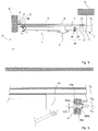
figure 1 représente une installation motorisée d'une porte de garage sectionnelle 1 constituée de panneaux 1a articulés autour de charnières 1 b. La porte 1 est reliée à un chariot 3 grâce à un bras coudé 2. Le chariot 3 se déplace le long d'un rail 4 en « U » inversé et fixé à un bâti B d'un bâtiment. Ce déplacement a lieu grâce à un lien souple 5, tel qu'une chaîne ou une courroie, disposé à l'intérieur du rail. Le lien souple 5 s'enroule autour de deux pignons ou poulies 6a et 6b. Le réglage de l'écartement des pignons ou poulies permet de régler la tension du lien souple 5. Un des deux pignons 6a est entraîné en rotation par un actionneur 7. Comme le chariot 3 est fixé sur le lien souple 5, l'actionneur 7 assure le mouvement en translation motorisée du chariot 3, parallèlement à l'axe longitudinal X4 du rail 4. Classiquement, le chariot 3 comprend un corps parallélépipédique logé dans le rail et une partie inférieure traversant l'ouverture du rail sur laquelle est attaché le bras coudé 2. Le poids de la porte est par ailleurs compensé par un ressort de compensation 8 entraînant en rotation un arbre 9 autour duquel s'enroule un câble 10 relié à l'extrémité du premier panneau de la porte. - Cette installation standard ne dispose pas de dispositif de maintien du chariot lorsque la porte est ouverte. Le ressort de compensation 8 exerce, via le câble 10, un effort important E1 sur la porte de garage qui tend à se refermer du fait du déplacement du chariot dans le sens de la flèche F1. En effet, le chariot est retenu uniquement par le frein intégré à l'actionneur 7. Or, les actionneurs standards ne freinent pas suffisamment pour bloquer le déplacement du chariot lorsqu'il est soumis à des efforts importants, tel que l'effort E1 généré par le ressort 8. Après un léger déplacement du chariot, la porte se stabilise pour atteindre une position telle que celle représentée à la
figure 1 . La hauteur H1 disponible pour accéder au garage est alors réduite par rapport à la hauteur H de l'ouverture ménagée dans le bâtiment pour accéder au garage. - Les figures suivantes représentent une installation motorisée d'une porte de garage sectionnelle 1 munie d'un dispositif de maintien 40 selon l'invention. Les
figures 2 et 3 illustrent l'installation dans une configuration porte fermée. Lesfigures 5 et 6 illustrent l'installation dans une configuration porte ouverte. Les éléments analogues à ceux de l'installation de lafigure 1 portent les mêmes références sur lesfigures 2 à 6 . - Comme dans l'installation de la
figure 1 , la porte 1 est solidaire d'un chariot 3 entraîné le long d'un rail 4 par un lieu souple 5, de type chaine ou courroie. Le chariot 3 est mobile entre une première position représentée auxfigures 2 et 3 , où la porte 1 est fermée, et une deuxième position représentée auxfigures 4 et5 , où la porte 1 est totalement ouverte. Le lien souple 5 s'enroule sur des pignons ou poulies 6a et 6b dont l'une est entraînée en rotation par un actionneur 7 de type moteur électrique. Un câble 10 relié à la porte s'enroule sur un arbre 9 soumis à l'action d'un ressort 8 de compensation du poids de la porte 1. L'actionneur 7 intègre un frein 71 et/ou un réducteur 72 au moins partiellement irréversible. Les organes 71 et/ou 72 constituent des moyens d'arrêt du chariot 3 dans l'une des positions desfigures 2 et5 ou dans une position intermédiaire entre ces positions. En variante, les organes 71 et/ou 72 peuvent être adjacents au corps de l'actionneur 7, tout en faisant partie de celui-ci. - Le garage est accessible à travers une ouverture O dont on note H la hauteur.
- Le dispositif de maintien 40 comprend deux parties, à savoir un nez 20 et un dispositif de pression 30.
- Le nez 20 est fixé à une partie 3A du chariot 3 qui fait saillie hors du rail 4. Ce nez s'étend en direction de l'actionneur 7, selon un axe X20 parallèle à l'axe X4. Il comporte une gorge 22 suivie d'une partie tronconique 21 formant l'extrémité du nez. La base de la partie tronconique, dont on note D20 le diamètre, constitue une des limites latérales de la gorge 22.
- Le dispositif de pression 30 comprend un boîtier 31 fixé sur le rail 4 à une position précise matérialisant la fin de course du chariot. Cette position est réglable en fonction de la course sélectionnée pour la porte 1 et de la position ouverte voulue pour cette porte. Le boîtier 31 comporte une ouverture cylindrique traversante 32 dont l'axe X30 est sensiblement confondu avec l'axe X20 lorsque le chariot 3 est au voisinage du boîtier 31. Le diamètre D32 de l'ouverture est supérieur au diamètre de base D20 de la partie tronconique 21 du nez 20. En conséquence, le nez peut entièrement pénétrer dans l'ouverture 32 du boîtier 31. Le dispositif de pression comprend en outre deux organes presseurs, 35a et 35b, disposés chacun dans un trou taraudé 33a, 33b du boîtier 31 et situés à 180° l'un par rapport à l'autre, au même niveau axial sur l'axe X30- Chaque trou 33a ou 33b est perpendiculaire à l'axe X30 et débouche dans l'ouverture 32.
- La composition d'un organe presseur 35 est illustrée à la
figure 4 . Il comporte une enveloppe cylindrique 351 pourvue d'un fond 356 et dans laquelle s'insèrent un ressort hélicoïdal 353 et une bille 354. L'enveloppe cylindrique 351 est filetée sur sa surface radiale extérieure, de manière à coopérer avec le taraudage du trou correspondant 33a ou 33b. Un trou borgne 352 forme l'intérieur de l'enveloppe cylindrique 351. Le diamètre D352 du trou borgne 352 est légèrement supérieur au diamètre D354 de la bille 354 et au diamètre extérieur D353 du ressort 353. Le ressort hélicoïdal 353 est en appui, par une extrémité, sur le fond 356 et en contact, par son autre extrémité, avec la bille 354. Le trou borgne 352 est délimité par une collerette 355 à son entrée. Le diamètre intérieur D355 de la collerette 355 est légèrement inférieur au diamètre D354 de la bille. Cette collerette peut être une pièce rapportée ou peut être réalisée par déformation plastique de l'enveloppe 351. Ainsi, la collerette 355 permet de maintenir la bille 354 dans son logement 352. Le dimensionnement des éléments de l'organe presseur 35 est tel que la bille 354 appuie sur la collerette 355 quand elle est sollicitée uniquement par le ressort 353. Un organe presseur est caractérisé par l'effort nécessaire pour déplacer sa bille dans son logement d'une distance déterminée. Cette caractéristique est directement liée à la raideur du ressort 353 utilisé. - La position des organes presseurs 35a et 35b peut être ajustée dans leurs logements 33a, 33b grâce aux filetages et taraudages des parties 351, 33a et 33b. Ainsi, le diamètre intérieur sur billes D35 entre deux billes 354a et 354b des deux organes presseurs 35a et 35b peut être réglé pour être inférieur au diamètre de base D20 du nez 20. En conséquence, en déplaçant le nez à l'intérieur de l'ouverture 32 du dispositif de pression 30 dans le sens de la flèche F2 à la
figure 3 , la partie tronconique 21 du nez vient au contact avec les billes 354a et 354b. Un effort est donc nécessaire pour amener le nez 20 dans une position, dite de fin de course, où les billes 354a et 354b se logent dans la gorge 22, telle que représentée auxfigures 5 et 6 . Cette position correspond à la fin de course du chariot 3 pour laquelle la porte est ouverte. Cet effort est directement lié à la compression des ressorts dans les organes presseurs 35a et 35b. - L'effort d'insertion du nez 20 dans le boîtier 31, pour l'amener dans sa position de fin de course, correspond à l'effort d'activation du dispositif de maintien 40.
- A l'inverse, l'effort d'extraction du nez 20 du boîtier 31 correspond à l'effort de désactivation du dispositif de maintien 40. Dans ce cas, les billes 354a et 354b doivent s'échapper de la gorge 22. Compte tenu des pentes de part et d'autre du diamètre de base D20, les intensités des efforts d'activation et de désactivation diffèrent. Ainsi, la pente du tronc de cône 21 par rapport à l'axe X20 permet de réduire l'intensité de l'effort d'activation et de le rendre progressif, sur la course du nez 20 entre les organes presseurs 35a et 35b. A contrario, la pente par rapport à l'axe X20 de la paroi latérale de la gorge 22 du côté de la rampe 21 est plus raide, ce qui augmente l'intensité de l'effort de désactivation.
- Pour ajuster les efforts d'activation ou de désactivation du dispositif de maintien 40, il est possible de faire varier la pente de la partie tronconique 21 du nez 20, la pente de la paroi latérale 22A de la gorge 22 du nez, le nombre et la position des organes presseurs 35a et 35b et les caractéristiques des organes presseurs, notamment la constance de raideur de leurs ressorts 353.
- Avantageusement, l'intensité de l'effort de désactivation du dispositif de maintien 40 est supérieure à l'intensité de la résultante R1 selon l'axe X4 de l'effort E1 de compensation de la porte de garage 1 quand le chariot 3 est dans sa position de fin de course des
figures 5 et 6 . Si l'intensité de l'effort de désactivation était inférieure à celle de cette résultante, le dispositif de maintien 40 ne serait pas fonctionnel car l'effort de compensation E1 suffirait à désactiver le dispositif de maintien 40 et le chariot 3 ne serait plus retenu. On se retrouverait alors dans le cas de configuration de lafigure 1 . En revanche, il est préférable que l'intensité de l'effort de désactivation soit légèrement supérieure à l'intensité de la résultante R1 pour que le dispositif de maintien puisse être aisément désactivé, lors d'une manoeuvre manuelle, après avoir débrayé l'actionneur 7. Cela permet également d'éviter un a-coup, source de bruit, au début de la course de fermeture de la porte et que l'actionneur doive fournir un effort important au début de cette course. - Lors de l'insertion du nez 20 dans l'ouverture 32 du dispositif de pression 30, les billes 354 des organes presseurs 35a et 35b glissent le long de la partie tronconique 21 qui forme une rampe d'amenée de ces billes vers la gorge 22. Lors de ce mouvement, un effort radial et centripète, par rapport aux axes X20 et X30 alors confondus, est exercé par les billes 354 des organes presseurs 35a et 35b sur la partie tronconique 21. Lorsque les billes 354 parviennent dans la gorge 22, les organes presseurs 35a et 35b peuvent également exercer un effort radial et centripète de moindre intensité ou ne plus exercer d'effort sur le nez 20. Cet effort radial et centripète est dû à l'action des ressorts 353 et son intensité est réglable en ajustant la position des enveloppes 351 dans les trous filetés 33a et 33b.
- L'introduction du nez 20 dans l'ouverture 32 du dispositif de pression 30 induit donc une activation automatique du dispositif de maintien 40 lorsque la porte 1 parvient dans sa position ouverte, c'est-à-dire lorsque le chariot 3 parvient dans sa deuxième position. Dans cette position, la porte 1 n'obture pas l'ouverture O dont la hauteur totale H est disponible pour donner accès au garage.
- L'activation du dispositif de maintien 40, qui agit sur le chariot 3 indépendamment du frein 71 et du réducteur 72, permet de soulager ces moyens d'arrêt lorsque le chariot parvient dans sa deuxième position. En effet, ces moyens d'arrêt ne sont alors plus soumis à l'action du chariot 3 et des éléments qui lui sont cinématiquement liés, tels que la porte 1 ou le ressort 8.
- Pour faciliter la compréhension, les
figures 2, 3 ,5 et 6 montrent les organes presseurs 35a et 35b dans un plan perpendiculaire au plan de l'ouverture O. Il est cependant préférable que les organes presseurs soient disposés dans un plan parallèle au sol, l'ajustement de la position de ces organes étant plus facilement réalisable. - L'invention n'est pas limitée à l'utilisation de deux organes presseurs. On peut en utiliser plus ou moins de deux.
- Le mode de réalisation représenté illustre un nez 20 muni d'une partie tronconique 21. Cependant, le nez peut être cylindrique à base circulaire et muni d'une gorge. De même, le nez peut avoir une forme non circulaire, une section carrée par exemple, et comprendre des rampes en vis-à-vis des organes presseurs. Dans ce cas, une indexation entre le nez et le dispositif de pression doit être prévue. Il n'est alors pas nécessaire d'avoir une gorge, un simple logement adapté localement suffit.
- De plus, l'agencement des éléments du dispositif de maintien 40 peut être inversé. Le dispositif de pression 30 peut être fixé sur le chariot 3 et le nez 20 fixé sur le rail 4.
- Un des éléments du dispositif de maintien 40 peut être fixé sur le carter de l'actionneur 7 au lieu du rail 4. Dans ce cas, le dispositif de maintien 40 est considéré comme indépendant de l'actionneur 7 car il n'est pas interne à l'actionneur, comme le sont un frein 71 ou un organe tel que le réducteur 72 assurant l'irréversibilité de la transmission.
- Bien entendu, d'autres organes presseurs peuvent être utilisés. Par exemple, on peut remplacer les billes 354 par des rouleaux. Le ou les organes presseurs peuvent être directement intégrés dans le boîtier 31, l'ajustement de la pression pouvant être réalisé en modifiant la position de l'extrémité d'une vis contre laquelle appuie le ressort.
- On peut également envisager d'autres dispositifs permettant d'obtenir le maintien du nez 20 en position. Par exemple, on peut utiliser un nez équipé de clips coopérant avec une simple bague. Ces clips peuvent être conçus pour permettre des efforts d'activation/désactivation différents.
- Par ailleurs, un des éléments du dispositif de maintien peut être fixé sur une partie d'un verrou anti-intrusion, lui-même fixé sur le chariot 3. Cette combinaison peut s'avérer plus facile à installer et à adapter aux différentes typologies de porte de garage.
- D'autre part, l'invention n'est pas limitée aux portes de garage sectionnelles compensées mais couvre tout type de porte, qu'elle soit compensée ou non.
Claims (15)
- Installation de porte de garage comprenant un actionneur (7) entraînant le déplacement d'un chariot (3) relié à la porte (1), entre une première position (fig. 2, 3) dans laquelle la porte est fermée et une deuxième (fig. 5, 6) position dans laquelle la porte est ouverte caractérisée en ce que l'installation comprend un dispositif (40) de maintien du chariot (3) dans sa deuxième position, indépendant de l'actionneur (7) et activé par l'arrivée du chariot (3) dans sa deuxième position.
- Installation de porte de garage selon la revendication 1 caractérisée en ce que le dispositif de maintien (40) comprend des moyens élastiques (35a, 35b) de maintien d'une pièce (20) solidaire du chariot (3) dans une configuration verrouillée où le chariot est dans sa deuxième position..
- Installation de porte de garage selon la revendication 2 caractérisée en ce que les moyens élastiques (35a, 35b) sont automatiquement activés par la pièce (20) solidaire du chariot (3), lorsque le chariot parvient dans sa deuxième position, pour verrouiller cette pièce en position.
- Installation de porte de garage selon l'une des revendications précédentes caractérisée en ce que l'intensité de l'effort d'activation du dispositif de maintien (40) est inférieure à l'intensité de l'effort de désactivation du dispositif de maintien.
- Installation de porte de garage selon la revendication 4 caractérisée en ce que l'effort d'activation et/ou l'effort de désactivation sont réglables.
- Installation de porte de garage selon l'une des revendications précédentes caractérisée en ce que l'installation comprend un moyen (8) de compensation du poids de la porte (1).
- Installation de porte de garage selon l'une des revendications précédentes caractérisée en ce que l'actionneur (7) comprend des moyens (71, 72) d'arrêt du chariot (3) en position, dans l'une de ses première et deuxième positions ou entre ces positions et en ce que le dispositif de maintien (40) agit sur le chariot dans sa deuxième position indépendamment des moyens d'arrêt.
- Installation de porte de garage selon l'une des revendications précédentes caractérisée en ce que le dispositif de maintien (40) comprend- un nez (20) et- un dispositif de pression (30) comportant au moins un organe presseur (35a, 35b) apte à exercer, sur le nez et via un élément de contact (354), un effort radial par rapport à un axe longitudinal (X20) du nez,en ce que le nez (20) comporte un logement (22) destiné à recevoir l'élément de contact (354) du ou de chaque organe presseur (35a, 35b),
et en ce que le dispositif de maintien (40) est activé quand l'élément de contact est reçu dans le logement (22). - Installation de porte de garage selon la revendication 8 caractérisée en ce que le nez (20) comprend une rampe (21) débouchant sur le logement (22).
- Installation de porte de garage selon la revendication précédente caractérisée en ce que l'organe presseur (35a, 35b) exerce un effort radial sur la rampe (21).
- Installation de porte de garage selon l'une des revendications 9 ou 10 caractérisée en ce que la rampe est formée par une partie tronconique (21) du nez (20).
- Installation de porte de garage selon l'une des revendications 8 à 11 caractérisée en ce que l'élément de contact est une bille (354) maintenue en pression contre le nez (20) grâce à un ressort (353).
- Installation de porte de garage selon l'une des revendications 8 à 12 caractérisée en ce que le nez (20) est solidaire du chariot (3).
- Installation de porte de garage selon l'une des revendications précédentes caractérisée en ce qu'un des éléments (20, 30) du dispositif de maintien (40) est solidaire d'un verrou anti-intrusion fixé sur le chariot (3).
- Installation de porte de garage selon l'une des revendications précédentes caractérisée en ce qu'une fois le dispositif de maintien (40) activé, la porte de garage (1), compensée ou non, exerce sur le dispositif de maintien (40) un effort (E1) dont la résultante (R1) sur un axe (X4) parallèle à la direction de déplacement du chariot (3) a une intensité inférieure à un effort de désactivation du dispositif de maintien.
Priority Applications (1)
| Application Number | Priority Date | Filing Date | Title |
|---|---|---|---|
| PL11150543T PL2343430T3 (pl) | 2010-01-12 | 2011-01-11 | Instalacja drzwi garażowych z siłownikiem i ruchomym wózkiem |
Applications Claiming Priority (1)
| Application Number | Priority Date | Filing Date | Title |
|---|---|---|---|
| FR1050169A FR2955140B1 (fr) | 2010-01-12 | 2010-01-12 | Installation de porte de garage avec actionneur et chariot mobile |
Publications (2)
| Publication Number | Publication Date |
|---|---|
| EP2343430A1 true EP2343430A1 (fr) | 2011-07-13 |
| EP2343430B1 EP2343430B1 (fr) | 2016-11-16 |
Family
ID=42558553
Family Applications (1)
| Application Number | Title | Priority Date | Filing Date |
|---|---|---|---|
| EP11150543.4A Active EP2343430B1 (fr) | 2010-01-12 | 2011-01-11 | Installation de porte de garage avec actionneur et chariot mobile |
Country Status (3)
| Country | Link |
|---|---|
| EP (1) | EP2343430B1 (fr) |
| FR (1) | FR2955140B1 (fr) |
| PL (1) | PL2343430T3 (fr) |
Cited By (1)
| Publication number | Priority date | Publication date | Assignee | Title |
|---|---|---|---|---|
| CN113153031A (zh) * | 2021-04-20 | 2021-07-23 | 南京康尼机电股份有限公司 | 一种门系统隔离装置 |
Citations (5)
| Publication number | Priority date | Publication date | Assignee | Title |
|---|---|---|---|---|
| US2542432A (en) * | 1947-10-20 | 1951-02-20 | Harold L Cook | Automatic door operating mechanism |
| US2643714A (en) * | 1950-08-10 | 1953-06-30 | Frantz Mfg Co | Overhead door structure |
| US3584414A (en) * | 1969-10-29 | 1971-06-15 | Steiner American Corp | Door control mechanism |
| US3733747A (en) * | 1972-03-01 | 1973-05-22 | Crane Co H W | Door operating mechanism |
| EP0743416A1 (fr) | 1995-05-19 | 1996-11-20 | Hörmann KG Verkaufsgesellschaft | Dispositif d'entraînement pour un panneau de porte |
Family Cites Families (1)
| Publication number | Priority date | Publication date | Assignee | Title |
|---|---|---|---|---|
| US7036548B2 (en) * | 2004-03-17 | 2006-05-02 | Wayne-Dalton Corp. | Method and apparatus for positioning a sectional door relative to an opening |
-
2010
- 2010-01-12 FR FR1050169A patent/FR2955140B1/fr not_active Expired - Fee Related
-
2011
- 2011-01-11 EP EP11150543.4A patent/EP2343430B1/fr active Active
- 2011-01-11 PL PL11150543T patent/PL2343430T3/pl unknown
Patent Citations (5)
| Publication number | Priority date | Publication date | Assignee | Title |
|---|---|---|---|---|
| US2542432A (en) * | 1947-10-20 | 1951-02-20 | Harold L Cook | Automatic door operating mechanism |
| US2643714A (en) * | 1950-08-10 | 1953-06-30 | Frantz Mfg Co | Overhead door structure |
| US3584414A (en) * | 1969-10-29 | 1971-06-15 | Steiner American Corp | Door control mechanism |
| US3733747A (en) * | 1972-03-01 | 1973-05-22 | Crane Co H W | Door operating mechanism |
| EP0743416A1 (fr) | 1995-05-19 | 1996-11-20 | Hörmann KG Verkaufsgesellschaft | Dispositif d'entraînement pour un panneau de porte |
Cited By (1)
| Publication number | Priority date | Publication date | Assignee | Title |
|---|---|---|---|---|
| CN113153031A (zh) * | 2021-04-20 | 2021-07-23 | 南京康尼机电股份有限公司 | 一种门系统隔离装置 |
Also Published As
| Publication number | Publication date |
|---|---|
| EP2343430B1 (fr) | 2016-11-16 |
| FR2955140B1 (fr) | 2014-02-28 |
| FR2955140A1 (fr) | 2011-07-15 |
| PL2343430T3 (pl) | 2017-05-31 |
Similar Documents
| Publication | Publication Date | Title |
|---|---|---|
| EP2944831B1 (fr) | Dispositif de fixation pour fixer un panneau à une structure, et aéronef | |
| EP3529516B1 (fr) | Motoreducteur compact | |
| EP0415820A1 (fr) | Mécanisme réducteur pour articulation sans jeu utilisable notamment pour le réglage de diverses parties d'un siège de véhicule automobile | |
| EP2735089B1 (fr) | Dispositif d'entrainement a moteur electrique et reducteur | |
| FR2672040A1 (fr) | Ensemble a rouleaux d'entrainement. | |
| FR2695083A1 (fr) | Entraînement par moyeu de roue constitué d'un moteur d'entraînement et d'un réducteur planétaire monté en aval. | |
| CA2961276A1 (fr) | Dispositif de couplage electrique extensible pour station de recharge de vehicule electrique | |
| EP2343430B1 (fr) | Installation de porte de garage avec actionneur et chariot mobile | |
| EP3187759A1 (fr) | Dispositif de transmission de mouvement par engrenage et système d'actionnement le comprenant | |
| EP0726172A1 (fr) | Dispositif de montage de roue et bac roulant pour la collecte de déchets muni d'un tel dispositif | |
| FR3021253A1 (fr) | Dispositif vitre affleurant pour porte de vehicule a panneau mobile reglable, porte et vehicule automobile correspondants. | |
| EP3093623B1 (fr) | Dispositif de detection d'une position angulaire d'un organe rotatif, systeme comprenant un tel dispositif et rideau integrant un tel systeme | |
| EP3379105B1 (fr) | Élément d'engrenage à rouleaux | |
| EP3821104B1 (fr) | Système d'entraînement d'un écran et installation comprenant un tel système | |
| FR3008130A1 (fr) | Dispositif de manœuvre d'un equipement de fermeture ou de protection solaire | |
| FR2800121A1 (fr) | Dispositif de manoeuvre pour volet roulant, store et similaire, a commande par manivelle comportant un systeme limiteur de couple | |
| WO2020025578A1 (fr) | Système d'entraînement d'un écran et installation de fermeture ou de protection solaire comprenant un tel système | |
| EP2226454B1 (fr) | Dispositif d'ouverture de porte et ensemble comportant une porte équipé d'un tel dispositif | |
| EP1283323A1 (fr) | Dispositif d'entraínement de lève-vitre avec des moyens de maintien du tambour dans son boítier | |
| FR2797245A1 (fr) | Caisse de vehicule de transport routier et vehicule de transport routier pourvu d'une telle caisse | |
| EP1640555B1 (fr) | Dispositif d'entraînement a débrayage automatique pour système de fermeture de bâtiment | |
| EP3830360B1 (fr) | Actionneur électromécanique, système d'entraînement d'un écran, installation de fermeture ou de protection solaire comprenant un tel système et procédé de remplacement d'une batterie dans un tel actionneur ou système | |
| FR2969685A1 (fr) | Dispositif universel pour la fermeture automatique d'un ouvrant coulissant, notamment porte de placard | |
| FR2803357A1 (fr) | Ensemble de commande pour boite de vitesses robotisee | |
| FR2957964A1 (fr) | Porte basculante motorisee |
Legal Events
| Date | Code | Title | Description |
|---|---|---|---|
| PUAI | Public reference made under article 153(3) epc to a published international application that has entered the european phase |
Free format text: ORIGINAL CODE: 0009012 |
|
| AK | Designated contracting states |
Kind code of ref document: A1 Designated state(s): AL AT BE BG CH CY CZ DE DK EE ES FI FR GB GR HR HU IE IS IT LI LT LU LV MC MK MT NL NO PL PT RO RS SE SI SK SM TR |
|
| AX | Request for extension of the european patent |
Extension state: BA ME |
|
| 17P | Request for examination filed |
Effective date: 20120112 |
|
| 17Q | First examination report despatched |
Effective date: 20120705 |
|
| GRAP | Despatch of communication of intention to grant a patent |
Free format text: ORIGINAL CODE: EPIDOSNIGR1 |
|
| RIC1 | Information provided on ipc code assigned before grant |
Ipc: E05F 15/668 20150101AFI20151216BHEP Ipc: E05C 17/52 20060101ALN20151216BHEP Ipc: E05D 13/00 20060101ALN20151216BHEP Ipc: E05B 65/00 20060101ALI20151216BHEP Ipc: E05F 15/681 20150101ALI20151216BHEP |
|
| INTG | Intention to grant announced |
Effective date: 20160108 |
|
| REG | Reference to a national code |
Ref country code: DE Ref legal event code: R079 Ref document number: 602011032362 Country of ref document: DE Free format text: PREVIOUS MAIN CLASS: E05F0015160000 Ipc: E05F0015668000 |
|
| GRAP | Despatch of communication of intention to grant a patent |
Free format text: ORIGINAL CODE: EPIDOSNIGR1 |
|
| RIC1 | Information provided on ipc code assigned before grant |
Ipc: E05C 17/52 20060101ALN20160602BHEP Ipc: E05F 15/681 20150101ALI20160602BHEP Ipc: E05B 65/00 20060101ALI20160602BHEP Ipc: E05F 15/668 20150101AFI20160602BHEP Ipc: E05D 13/00 20060101ALN20160602BHEP |
|
| INTG | Intention to grant announced |
Effective date: 20160617 |
|
| GRAS | Grant fee paid |
Free format text: ORIGINAL CODE: EPIDOSNIGR3 |
|
| GRAA | (expected) grant |
Free format text: ORIGINAL CODE: 0009210 |
|
| AK | Designated contracting states |
Kind code of ref document: B1 Designated state(s): AL AT BE BG CH CY CZ DE DK EE ES FI FR GB GR HR HU IE IS IT LI LT LU LV MC MK MT NL NO PL PT RO RS SE SI SK SM TR |
|
| REG | Reference to a national code |
Ref country code: GB Ref legal event code: FG4D Free format text: NOT ENGLISH |
|
| REG | Reference to a national code |
Ref country code: CH Ref legal event code: EP |
|
| REG | Reference to a national code |
Ref country code: IE Ref legal event code: FG4D Free format text: LANGUAGE OF EP DOCUMENT: FRENCH |
|
| REG | Reference to a national code |
Ref country code: AT Ref legal event code: REF Ref document number: 846128 Country of ref document: AT Kind code of ref document: T Effective date: 20161215 |
|
| REG | Reference to a national code |
Ref country code: FR Ref legal event code: PLFP Year of fee payment: 7 |
|
| REG | Reference to a national code |
Ref country code: DE Ref legal event code: R096 Ref document number: 602011032362 Country of ref document: DE |
|
| REG | Reference to a national code |
Ref country code: DE Ref legal event code: R096 Ref document number: 602011032362 Country of ref document: DE |
|
| PG25 | Lapsed in a contracting state [announced via postgrant information from national office to epo] |
Ref country code: LV Free format text: LAPSE BECAUSE OF FAILURE TO SUBMIT A TRANSLATION OF THE DESCRIPTION OR TO PAY THE FEE WITHIN THE PRESCRIBED TIME-LIMIT Effective date: 20161116 |
|
| REG | Reference to a national code |
Ref country code: NL Ref legal event code: MP Effective date: 20161116 |
|
| REG | Reference to a national code |
Ref country code: LT Ref legal event code: MG4D |
|
| REG | Reference to a national code |
Ref country code: AT Ref legal event code: MK05 Ref document number: 846128 Country of ref document: AT Kind code of ref document: T Effective date: 20161116 |
|
| PG25 | Lapsed in a contracting state [announced via postgrant information from national office to epo] |
Ref country code: SE Free format text: LAPSE BECAUSE OF FAILURE TO SUBMIT A TRANSLATION OF THE DESCRIPTION OR TO PAY THE FEE WITHIN THE PRESCRIBED TIME-LIMIT Effective date: 20161116 Ref country code: GR Free format text: LAPSE BECAUSE OF FAILURE TO SUBMIT A TRANSLATION OF THE DESCRIPTION OR TO PAY THE FEE WITHIN THE PRESCRIBED TIME-LIMIT Effective date: 20170217 Ref country code: NL Free format text: LAPSE BECAUSE OF FAILURE TO SUBMIT A TRANSLATION OF THE DESCRIPTION OR TO PAY THE FEE WITHIN THE PRESCRIBED TIME-LIMIT Effective date: 20161116 Ref country code: LT Free format text: LAPSE BECAUSE OF FAILURE TO SUBMIT A TRANSLATION OF THE DESCRIPTION OR TO PAY THE FEE WITHIN THE PRESCRIBED TIME-LIMIT Effective date: 20161116 Ref country code: NO Free format text: LAPSE BECAUSE OF FAILURE TO SUBMIT A TRANSLATION OF THE DESCRIPTION OR TO PAY THE FEE WITHIN THE PRESCRIBED TIME-LIMIT Effective date: 20170216 |
|
| PG25 | Lapsed in a contracting state [announced via postgrant information from national office to epo] |
Ref country code: ES Free format text: LAPSE BECAUSE OF FAILURE TO SUBMIT A TRANSLATION OF THE DESCRIPTION OR TO PAY THE FEE WITHIN THE PRESCRIBED TIME-LIMIT Effective date: 20161116 Ref country code: FI Free format text: LAPSE BECAUSE OF FAILURE TO SUBMIT A TRANSLATION OF THE DESCRIPTION OR TO PAY THE FEE WITHIN THE PRESCRIBED TIME-LIMIT Effective date: 20161116 Ref country code: RS Free format text: LAPSE BECAUSE OF FAILURE TO SUBMIT A TRANSLATION OF THE DESCRIPTION OR TO PAY THE FEE WITHIN THE PRESCRIBED TIME-LIMIT Effective date: 20161116 Ref country code: PT Free format text: LAPSE BECAUSE OF FAILURE TO SUBMIT A TRANSLATION OF THE DESCRIPTION OR TO PAY THE FEE WITHIN THE PRESCRIBED TIME-LIMIT Effective date: 20170316 Ref country code: AT Free format text: LAPSE BECAUSE OF FAILURE TO SUBMIT A TRANSLATION OF THE DESCRIPTION OR TO PAY THE FEE WITHIN THE PRESCRIBED TIME-LIMIT Effective date: 20161116 Ref country code: HR Free format text: LAPSE BECAUSE OF FAILURE TO SUBMIT A TRANSLATION OF THE DESCRIPTION OR TO PAY THE FEE WITHIN THE PRESCRIBED TIME-LIMIT Effective date: 20161116 Ref country code: BE Free format text: LAPSE BECAUSE OF NON-PAYMENT OF DUE FEES Effective date: 20170131 |
|
| PG25 | Lapsed in a contracting state [announced via postgrant information from national office to epo] |
Ref country code: DK Free format text: LAPSE BECAUSE OF FAILURE TO SUBMIT A TRANSLATION OF THE DESCRIPTION OR TO PAY THE FEE WITHIN THE PRESCRIBED TIME-LIMIT Effective date: 20161116 Ref country code: RO Free format text: LAPSE BECAUSE OF FAILURE TO SUBMIT A TRANSLATION OF THE DESCRIPTION OR TO PAY THE FEE WITHIN THE PRESCRIBED TIME-LIMIT Effective date: 20161116 Ref country code: SK Free format text: LAPSE BECAUSE OF FAILURE TO SUBMIT A TRANSLATION OF THE DESCRIPTION OR TO PAY THE FEE WITHIN THE PRESCRIBED TIME-LIMIT Effective date: 20161116 Ref country code: CZ Free format text: LAPSE BECAUSE OF FAILURE TO SUBMIT A TRANSLATION OF THE DESCRIPTION OR TO PAY THE FEE WITHIN THE PRESCRIBED TIME-LIMIT Effective date: 20161116 Ref country code: EE Free format text: LAPSE BECAUSE OF FAILURE TO SUBMIT A TRANSLATION OF THE DESCRIPTION OR TO PAY THE FEE WITHIN THE PRESCRIBED TIME-LIMIT Effective date: 20161116 |
|
| REG | Reference to a national code |
Ref country code: DE Ref legal event code: R097 Ref document number: 602011032362 Country of ref document: DE |
|
| PG25 | Lapsed in a contracting state [announced via postgrant information from national office to epo] |
Ref country code: BG Free format text: LAPSE BECAUSE OF FAILURE TO SUBMIT A TRANSLATION OF THE DESCRIPTION OR TO PAY THE FEE WITHIN THE PRESCRIBED TIME-LIMIT Effective date: 20170216 Ref country code: SM Free format text: LAPSE BECAUSE OF FAILURE TO SUBMIT A TRANSLATION OF THE DESCRIPTION OR TO PAY THE FEE WITHIN THE PRESCRIBED TIME-LIMIT Effective date: 20161116 |
|
| REG | Reference to a national code |
Ref country code: CH Ref legal event code: PL |
|
| PLBE | No opposition filed within time limit |
Free format text: ORIGINAL CODE: 0009261 |
|
| STAA | Information on the status of an ep patent application or granted ep patent |
Free format text: STATUS: NO OPPOSITION FILED WITHIN TIME LIMIT |
|
| PG25 | Lapsed in a contracting state [announced via postgrant information from national office to epo] |
Ref country code: MC Free format text: LAPSE BECAUSE OF FAILURE TO SUBMIT A TRANSLATION OF THE DESCRIPTION OR TO PAY THE FEE WITHIN THE PRESCRIBED TIME-LIMIT Effective date: 20161116 |
|
| 26N | No opposition filed |
Effective date: 20170817 |
|
| GBPC | Gb: european patent ceased through non-payment of renewal fee |
Effective date: 20170216 |
|
| PG25 | Lapsed in a contracting state [announced via postgrant information from national office to epo] |
Ref country code: CH Free format text: LAPSE BECAUSE OF NON-PAYMENT OF DUE FEES Effective date: 20170131 Ref country code: LI Free format text: LAPSE BECAUSE OF NON-PAYMENT OF DUE FEES Effective date: 20170131 |
|
| REG | Reference to a national code |
Ref country code: IE Ref legal event code: MM4A |
|
| PG25 | Lapsed in a contracting state [announced via postgrant information from national office to epo] |
Ref country code: LU Free format text: LAPSE BECAUSE OF NON-PAYMENT OF DUE FEES Effective date: 20170111 Ref country code: SI Free format text: LAPSE BECAUSE OF FAILURE TO SUBMIT A TRANSLATION OF THE DESCRIPTION OR TO PAY THE FEE WITHIN THE PRESCRIBED TIME-LIMIT Effective date: 20161116 |
|
| REG | Reference to a national code |
Ref country code: FR Ref legal event code: PLFP Year of fee payment: 8 |
|
| REG | Reference to a national code |
Ref country code: BE Ref legal event code: MM Effective date: 20170131 |
|
| PG25 | Lapsed in a contracting state [announced via postgrant information from national office to epo] |
Ref country code: GB Free format text: LAPSE BECAUSE OF NON-PAYMENT OF DUE FEES Effective date: 20170216 Ref country code: IE Free format text: LAPSE BECAUSE OF NON-PAYMENT OF DUE FEES Effective date: 20170111 |
|
| PG25 | Lapsed in a contracting state [announced via postgrant information from national office to epo] |
Ref country code: MT Free format text: LAPSE BECAUSE OF FAILURE TO SUBMIT A TRANSLATION OF THE DESCRIPTION OR TO PAY THE FEE WITHIN THE PRESCRIBED TIME-LIMIT Effective date: 20161116 |
|
| PG25 | Lapsed in a contracting state [announced via postgrant information from national office to epo] |
Ref country code: HU Free format text: LAPSE BECAUSE OF FAILURE TO SUBMIT A TRANSLATION OF THE DESCRIPTION OR TO PAY THE FEE WITHIN THE PRESCRIBED TIME-LIMIT; INVALID AB INITIO Effective date: 20110111 |
|
| PG25 | Lapsed in a contracting state [announced via postgrant information from national office to epo] |
Ref country code: CY Free format text: LAPSE BECAUSE OF NON-PAYMENT OF DUE FEES Effective date: 20161116 |
|
| PG25 | Lapsed in a contracting state [announced via postgrant information from national office to epo] |
Ref country code: MK Free format text: LAPSE BECAUSE OF FAILURE TO SUBMIT A TRANSLATION OF THE DESCRIPTION OR TO PAY THE FEE WITHIN THE PRESCRIBED TIME-LIMIT Effective date: 20161116 |
|
| PG25 | Lapsed in a contracting state [announced via postgrant information from national office to epo] |
Ref country code: TR Free format text: LAPSE BECAUSE OF FAILURE TO SUBMIT A TRANSLATION OF THE DESCRIPTION OR TO PAY THE FEE WITHIN THE PRESCRIBED TIME-LIMIT Effective date: 20161116 |
|
| PG25 | Lapsed in a contracting state [announced via postgrant information from national office to epo] |
Ref country code: AL Free format text: LAPSE BECAUSE OF FAILURE TO SUBMIT A TRANSLATION OF THE DESCRIPTION OR TO PAY THE FEE WITHIN THE PRESCRIBED TIME-LIMIT Effective date: 20161116 Ref country code: IS Free format text: LAPSE BECAUSE OF FAILURE TO SUBMIT A TRANSLATION OF THE DESCRIPTION OR TO PAY THE FEE WITHIN THE PRESCRIBED TIME-LIMIT Effective date: 20170316 |
|
| REG | Reference to a national code |
Ref country code: DE Ref legal event code: R082 Ref document number: 602011032362 Country of ref document: DE Representative=s name: LAVOIX MUNICH, DE Ref country code: DE Ref legal event code: R081 Ref document number: 602011032362 Country of ref document: DE Owner name: SOMFY ACTIVITIES SA, FR Free format text: FORMER OWNER: SOMFY SAS, CLUSES, FR Ref country code: DE Ref legal event code: R081 Ref document number: 602011032362 Country of ref document: DE Owner name: SOMFY ACTIVITES SA, FR Free format text: FORMER OWNER: SOMFY SAS, CLUSES, FR |
|
| REG | Reference to a national code |
Ref country code: DE Ref legal event code: R082 Ref document number: 602011032362 Country of ref document: DE Representative=s name: LAVOIX MUNICH, DE Ref country code: DE Ref legal event code: R081 Ref document number: 602011032362 Country of ref document: DE Owner name: SOMFY ACTIVITES SA, FR Free format text: FORMER OWNER: SOMFY ACTIVITIES SA, CLUSES, FR |
|
| PGFP | Annual fee paid to national office [announced via postgrant information from national office to epo] |
Ref country code: DE Payment date: 20250116 Year of fee payment: 15 |
|
| PGFP | Annual fee paid to national office [announced via postgrant information from national office to epo] |
Ref country code: FR Payment date: 20251121 Year of fee payment: 16 |
|
| PGFP | Annual fee paid to national office [announced via postgrant information from national office to epo] |
Ref country code: PL Payment date: 20251219 Year of fee payment: 16 |
|
| PGFP | Annual fee paid to national office [announced via postgrant information from national office to epo] |
Ref country code: IT Payment date: 20260108 Year of fee payment: 16 |