EP2341748A2 - User equipment, base station, and method for frame transmission and reception - Google Patents
User equipment, base station, and method for frame transmission and reception Download PDFInfo
- Publication number
- EP2341748A2 EP2341748A2 EP10197101A EP10197101A EP2341748A2 EP 2341748 A2 EP2341748 A2 EP 2341748A2 EP 10197101 A EP10197101 A EP 10197101A EP 10197101 A EP10197101 A EP 10197101A EP 2341748 A2 EP2341748 A2 EP 2341748A2
- Authority
- EP
- European Patent Office
- Prior art keywords
- radio resource
- data
- control
- frame
- user equipment
- Prior art date
- Legal status (The legal status is an assumption and is not a legal conclusion. Google has not performed a legal analysis and makes no representation as to the accuracy of the status listed.)
- Withdrawn
Links
Images




Classifications
-
- H—ELECTRICITY
- H04—ELECTRIC COMMUNICATION TECHNIQUE
- H04W—WIRELESS COMMUNICATION NETWORKS
- H04W72/00—Local resource management
- H04W72/50—Allocation or scheduling criteria for wireless resources
- H04W72/54—Allocation or scheduling criteria for wireless resources based on quality criteria
- H04W72/543—Allocation or scheduling criteria for wireless resources based on quality criteria based on requested quality, e.g. QoS
-
- H—ELECTRICITY
- H04—ELECTRIC COMMUNICATION TECHNIQUE
- H04W—WIRELESS COMMUNICATION NETWORKS
- H04W72/00—Local resource management
- H04W72/20—Control channels or signalling for resource management
-
- H—ELECTRICITY
- H04—ELECTRIC COMMUNICATION TECHNIQUE
- H04W—WIRELESS COMMUNICATION NETWORKS
- H04W28/00—Network traffic management; Network resource management
- H04W28/16—Central resource management; Negotiation of resources or communication parameters, e.g. negotiating bandwidth or QoS [Quality of Service]
- H04W28/24—Negotiating SLA [Service Level Agreement]; Negotiating QoS [Quality of Service]
-
- H—ELECTRICITY
- H04—ELECTRIC COMMUNICATION TECHNIQUE
- H04W—WIRELESS COMMUNICATION NETWORKS
- H04W72/00—Local resource management
- H04W72/04—Wireless resource allocation
- H04W72/044—Wireless resource allocation based on the type of the allocated resource
- H04W72/0446—Resources in time domain, e.g. slots or frames
-
- H—ELECTRICITY
- H04—ELECTRIC COMMUNICATION TECHNIQUE
- H04W—WIRELESS COMMUNICATION NETWORKS
- H04W80/00—Wireless network protocols or protocol adaptations to wireless operation
Definitions
- Exemplary embodiments of the present invention relate to a user equipment, a method for frame transmission and reception using a radio resource of the user equipment, and a method for frame transmission using a radio resource of a base station.
- a packet protocol such as a File-Transfer Protocol (FTP)
- FTP File-Transfer Protocol
- traffic congestion may occur in a back-front of a radio interface in transmitting a data frame for the upload and a control frame for the download. Accordingly, a decrease in a data rate and a completion point in time of data transmission may not be determined.
- FTP File-Transfer Protocol
- a software algorithm may be added to an allocated radio resource.
- performance may not be accurately predicted.
- Exemplary embodiments of the present invention provide a user equipment that may stably support a quality of service (QoS) for a user by enabling traffic of a data frame and traffic of a control frame to not interfere with each other, a frame transmission and reception method using a radio resource of the user equipment, and a frame transmission method using a radio resource of a base station.
- QoS quality of service
- An exemplary embodiment of the present invention discloses a frame transmission method using a radio resource of a user equipment, the method including requesting a radio resource allocation if an application is generated in the user equipment; and receiving, in response to the request, an allocation of a data radio resource for a data frame and a control radio resource for a control frame.
- An exemplary embodiment of the present invention discloses a frame transmission method using a radio resource of a user equipment, the method including requesting a radio resource allocation if a plurality of applications is generated in the user equipment; receiving, in response to the request, an allocation of a plurality of data radio resources for a plurality of data frames and a single common control radio resource for a plurality of control frames; and transmitting the plurality of data frames using the plurality of data radio resources, respectively, and transmitting the plurality of control frames using the common control radio resource.
- An exemplary embodiment of the present invention discloses a frame reception method using a radio resource of a user equipment, the method including receiving, in the user equipment, a plurality of data frames using a plurality of corresponding data radio resources; receiving a plurality of control frames using a single common control radio resource; decompressing compression of the received data frames and control frames; and multiplexing the plurality of decompressed data frames and control frames to provide the plurality of multiplexed data frames and control frames to respective corresponding applications.
- An exemplary embodiment of the present invention discloses a frame transmission method using a radio resource of a base station, the method including receiving, in the base station, a request for a radio resource allocation; allocating, in response to the request, a data radio resource for a data frame and a control radio resource for a control frame; and transmitting the allocated data radio resource and the control radio resource.
- An exemplary embodiment of the present invention discloses a frame transmission method using a radio resource of a base station, the method including receiving, in the base station, a request for a radio resource allocation with respect to a plurality of applications; allocating, in response to the request, a plurality of data radio resources for a plurality of data frames and a single common control radio resource for a plurality of control frames; and transmitting the plurality of allocated data radio resources and the common control radio resource.
- An exemplary embodiment of the present invention discloses a user equipment including a first layer manager to request a radio resource allocation if an application is generated in the user equipment; and a second layer manager to receive, in response to the request, a data radio resource for a data frame and a control radio resource for a control frame, and to transmit the data frame and the control frame using the allocated data radio resource and the control radio resource, respectively.
- An exemplary embodiment of the present invention discloses a user equipment including a plurality of first layer managers each to request a radio resource allocation if a plurality of applications is generated in the user equipment; and a second layer manager to receive, in response to the request, a plurality of data radio resources for a plurality of data frames and a single common control radio resource for a plurality of control frames, to transmit the plurality of data frames using the plurality of data radio resources, respectively, and to transmit the plurality of control frames using the common control radio resource.
- An exemplary embodiment of the present invention discloses a system for frame transmission and reception, the system including a user equipment to manage an application; and a base station to allocate a radio resource to the user equipment, wherein the user equipment includes: a first layer manager to request a radio resource allocation if an application is generated in the user equipment, and a second layer manager to receive, from the base station in response to the request, a data radio resource for a data frame and a control radio resource for a control frame.
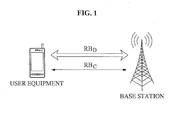
- FIG. 1 is a diagram illustrating a user equipment and a base station for a radio resource allocation of a transmission layer according to an exemplary embodiment of the present invention.
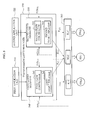
- FIG. 2 is a block diagram illustrating the user equipment or the base station of FIG. 1 .
- FIG. 3 is a diagram illustrating a user equipment and a base station for a radio resource allocation of a transmission layer according to an exemplary embodiment of the present invention.
- FIG. 4 is a diagram illustrating a user equipment and a base station for a radio resource allocation of a transmission layer according to an exemplary embodiment of the present invention.
- FIG. 5 is a block diagram illustrating the user equipment or the base station of FIG. 4 .
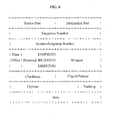
- FIG. 6 is a diagram to illustrating information for identifying a control frame and a data frame according to an exemplary embodiment of the present invention.
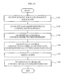
- FIG. 8 is a flowchart illustrating a frame transmission method using a radio resource of a user equipment according to an exemplary embodiment of the present invention.
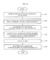
- FIG. 9 is a flowchart illustrating a frame transmission method using a radio resource of a user equipment according to an exemplary embodiment of the present invention.
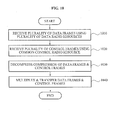
- FIG. 10 is a flowchart illustrating a frame reception method using a radio resource of a user equipment according to an exemplary embodiment of the present invention.
- FIG. 11 is a flowchart illustrating a frame transmission method using a radio resource of a base station according to an exemplary embodiment of the present invention.
- FIG. 12 is a flowchart illustrating a frame transmission method using a radio resource of a base station according to an exemplary embodiment of the present invention.
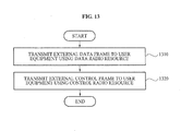
- FIG. 13 is a flowchart illustrating a frame transmission method using a radio resource of a base station according to an exemplary embodiment of the present invention.
- the user equipment denotes a device, such as a mobile terminal, for example, a laptop, a mobile phone, a smart phone, or a computer.
- the base station denotes a device for communication between the user equipment and a network server.
- the user equipment and the base station may bi-directionally transmit user data using a packet protocol, such as a Transmission Control Protocol (TCP).
- TCP Transmission Control Protocol
- the base station may be, for example, a macro base station installed in a macro cell or a small base station installed in a small cell.
- the small cell may include, for example, a femto cell, a pico cell, a home node B, home EnB, and the like.
- the packet protocol may include a data frame and a control frame.
- a separate radio resource may be allocated to each of the data frame and the control frame to transmit the data frame and the control frame.
- the radio resource may include, for example, a radio bearer (RB).
- RB D is allocated as a radio resource for transmission of the data frame
- RB C is allocated as a radio resource for transmission of the control frame.
- the user equipment and the base station may transmit the data frame and the control frame using RB D and RB C , respectively. Accordingly, it is possible to prevent congestion that may occur if different types of frames are transmitted via a single radio resource. In addition, it may be possible to prevent a decrease in a transmission and reception rate, and to more accurately predict an amount of time for transmission and reception.
- the packet protocol the TCP, a transmission protocol, a Packet Data Protocol (PDP) context, application data, and the like may be used together depending on ease of description, and may be translated as having equivalent meaning.
- PDP Packet Data Protocol
- FIG. 2 is a block diagram illustrating the user equipment or the base station of FIG. 1 .
- an application unit 210 may generate application data according to a user request.
- a single PDP context may be activated and a first layer manager 220 may request the base station for a radio resource allocation.
- the base station may allocate two radio resources to each single PDP context.
- the single PDP context that is, the application data
- the single PDP context may be classified into a data frame F D and a control frame F C , and the data frame F D and the control frame F C may be transmitted using different radio resources, respectively.
- the flow controller 221 may operate using feedback of a lower layer. Accordingly, the flow controller 221 may verify flow control status information to verify whether the data frame F D and the control frame F C are transmittable.
- the flow controller 221 may verify, from flow control status information FCI D and FCI C , a flow control status of each of the data frame F D and the control frame F C fed back from a second layer manager 230. If the flow control for each frame type is set as "enable", the flow controller 221 may verify the flow control status. Accordingly, it may be possible to prevent each frame from being randomly transmitted.
- a corresponding frame may be determined to be transmittable, and thus, the flow controller 221 may transmit the corresponding frame through the demultiplexer 223 using a physical resource.
- the demultiplexer 223 may classify, that is, demultiplex, the packet protocol into the data frame F D and the control frame F C in order to transmit data input from the application unit 210.
- the demultiplexer 223 may classify the frame type of the packet protocol into the data frame F D and the control frame F C by verifying header information.
- the demultiplexer 223 of the TCP/IP layer may determine, as a control frame F C , a type of a frame designated in FIG. 6 .
- the flow controller 221 may output the classified data frame F D and the classified control frame F C to the second layer manager 230.
- the second layer manager 230 may receive an allocation of a data radio resource RB D for the data frame F D and a control radio resource RB C for the control frame F C .
- the second layer manager 230 may be, for example, a radio link control (RLC) module managing transmission and reception of data to a network.
- the data radio resource RB D and the control radio resource RB C may be allocated by the base station and be transmitted to the user equipment.
- the radio resource may be used in a radio link layer.
- the data frame F D and the control frame F C that are Service Data Units (SDUs) may be segmented into Protocol Data Units (PDUs), and may be transmitted to the corresponding base station.
- SDUs Service Data Units
- PDUs Protocol Data Units
- the second layer manager 230 may transmit, to the base station, the data frame F D and the control frame F C using the data radio resource RB D and the control radio resource RB C , respectively.
- the base station may receive, from the user equipment, the data frame F D and the control frame F C using the allocated data radio resource RB D and the control radio resource RB C , respectively, and may transfer the received data frame F D and the control frame F C to a corresponding PDP Service Access Point (SAP) to transmit to a server (not shown).
- SAP PDP Service Access Point
- a SAP may denote an access point defined for each service for exchange of an upper application program and a message between layers, for example, a port.
- FIG. 2 may also illustrate the base station, in which case the base station may receive a frame from an external device (not shown), such as a server, using a packet protocol.
- the demultiplexer 223 of the base station may demultiplex the received frame according to a type of the frame and classify the frame into an external data frame and an external control frame.
- the second layer manager 230 may transmit, to the user equipment, the external data frame and the external control frame using the data radio resource RB D and the control radio resource RB C , respectively, allocated to the user equipment.
- the user equipment may transfer the received external data frame and the external control frame to a SAP corresponding to a PDP context.
- FIG. 3 is a diagram illustrating a user equipment and a base station for a radio resource allocation of a transmission layer according to an exemplary embodiment of the present invention.
- a plurality of applications may be generated in the user equipment.
- the user equipment may request the base station for a radio resource allocation together with a number of generated PDP contexts.
- the base station may allocate, with respect to each of the applications, each one of data radio resources for a data frame and control radio resources for a control frame.
- a first data frame F D1 and a first control frame F C1 corresponding to a first application or a first PDP context may be transmitted using a first data radio resource RB D1 and a first control radio resource RB C1 , respectively.
- a second data frame F D2 and a second control frame F C2 corresponding to a second application or a second PDP context may be transmitted using a second data radio resource RB D2 and a second control radio resource RB C2 , respectively.
- the first control radio resource RB C1 and the second control radio resource RB C2 may be used for transmission of the control frame of the packet protocol.
- the control frame may be defined in a transmission protocol, such as a TCP.
- FIG. 4 is a diagram illustrating a user equipment and a base station for a radio resource allocation of a transmission layer according to an exemplary embodiment of the present invention.
- FIG. 4 illustrates a case in which a common radio resource is used for a control frame.
- a control frame of each PDP context may be transmitted based on an SDU using the common radio resource.
- the base station may receive each control frame and transfer the each control frame to a corresponding PDP SAP.
- the base station may allocate a separate data radio resource RB D1 and RB D2 to each data frame, and may allocate a single common control radio resource RB C to each control frame.
- Control frames of different application data may be transmitted from the user equipment to the base station or from the base station to the user equipment using the same common control radio resource RB C .
- FIG. 5 is a block diagram illustrating the user equipment or the base station of FIG. 4 .
- a first application unit 510 may generate first application data according to a user request
- a second application unit 520 may generate second application data.
- a transmission layer manager 530 may manage transmission and reception using a packet protocol, such as a TCP/IP, and may verify header information of the packet protocol, that is, application data, to classify the packet protocol into a data frame and a control frame.
- the transmission layer manager 530 may transmit the data frame and the control frame using a corresponding data radio resource and a common control radio resource.
- a first flow controller 541 may verify a flow control status of each of the first data frame F D1 and the first control frame F C1 from flow control status information FCI D1 and FCI C1 , fed back from a third layer manager 560, to verify whether the first data frame F D1 and/or the first control frame F C1 is transmittable.
- a second flow controller 551 may verify a flow control status of each of the second data frame F D2 and the second control frame F C2 from flow control status information FCI D2 and FCI C2 , fed back from the third layer manager 560, to verify whether the second data frame F D2 and/or the second control frame F C2 is transmittable. If the second data frame F D2 and/or the second control frame F C2 is verified to be transmittable, a second demultiplexer 553 may demultiplex a packet protocol, for example, a TCP input from the second application 520, to classify the packet protocol into the second data frame F D2 and the second control frame F C2 .
- a packet protocol for example, a TCP input from the second application 520
- the first flow controller 541 and second flow controller 551 may output, to the third layer manager 560, the first and the second frames F D1 and F D2 and the first and the second control frames F C1 and F C2 classified by the respective first demultiplexer 543 and second demultiplexer 553.
- the third layer manager 560 may transmit the first data frame F D1 to the base station using the first data radio resource RB D1 for transmission of the first data frame F D1 , and may transmit the second data frame F D2 to the base station using the second data radio resource RB D2 for transmission of the second data frame F D2 . Also, the third layer manager 560 may transmit the first control frame F C1 and the second control frame F C2 to the base station using the allocated common control radio resource RB C .
- the third layer manager 560 may include an RLC module or multiple RLC modules configured to support transmission and reception of data according to a radio resource.
- the base station may transfer, to corresponding PDP SAPs, the first data frame F D1 and the second data frame F D2 that are received from the user equipment using the first data radio resource RB D1 and the second data radio resource RB D2 . Also, the base station may generate an SDU by collecting PDUs of the first control frame F C1 and the second control frame F C2 received using the common control radio resource RB C , and may transfer the SDU to a corresponding PDP SAP.
- the user equipment or the base station may identify a corresponding PDP SAP according to one of the following two methods.
- a reception side for example, the base station, may verify ID information, for example, an IP address, of a transmission side, for example, the user equipment, and may transfer an SDU to a PDP SAP corresponding to the verified IP address.
- the base station of FIG. 5 may be configured to be the same as the base station of FIG. 2 .
- the base station may classify, into an external data frame and an external control frame, a packet protocol received from a server (not shown) by demultiplexing the packet protocol according to a frame type.
- the base station may transmit the external data frame and the external control frame to the user equipment using a data radio resource and a control radio resource allocated to the user equipment.
- the user equipment may transfer the received external data frame and external control frame to an SAP corresponding to a PDP context.
- FIG. 6 is a diagram to illustrating information for identifying a control frame and a data frame according to an exemplary embodiment of the present invention.
- a demultiplexer for example, the demultiplexer 223, the first demultiplexer 543, or the second demultiplexer 553, may classify frames of a type into control frames as shown in FIG. 6 .
- Information used to classify the frames may use a frame format defined in a Request for Comments (RFC) document published by the Internet Engineering Task Force (IETF), for example, RFC 1180, which is incorporated herein by reference.
- RFC Request for Comments
- FIG. 6 a control bit used for classification of a control frame may be indicated as maximum six bits.
- Types of the control frame may include an Urgent Pointer field significant (URG) frame, an Acknowledgement field significant (ACK) frame, a Push Function (PSH) frame, a Reset the connection (RST) frame, a Synchronize sequence numbers (SYN) frame, and a No more data from sender (FIN) frame.
- UUG Urgent Pointer field significant
- ACK Acknowledgement field significant
- PSH Push Function
- RST Reset the connection
- SYN Synchronize sequence numbers
- FIN No more data from sender
- FIG. 7 is a block diagram illustrating a user equipment to receive a frame using a radio resource according to an exemplary embodiment of the present invention.
- a user equipment including a first application unit 750 and a second application unit 760 using different IP addresses multiplexes received frames will be described with reference to FIG. 7 .
- a third layer manager 710 may receive a plurality of data frames using a plurality of data radio resources corresponding to the plurality of data frames, and may receive a plurality of control frames using a single common control radio resource or a plurality of control radio resources. For example, the third layer manager 710 may receive a first data frame F D1 using a first data radio resource RB D1 , receive a second data frame F D2 using a second data radio resource RB D2 , and receive a first control frame F C1 and a second control frame F C2 using a common control radio resource RB C .
- the packet compression manager 720 may decompress compression of the first data frame F D1 , the second data frame F D2 , the first control frame F C1 , and the second control frame F C2 .
- the packet compression manager 720 may be, for example, a Packet Data Convergence Protocol (PDCP) module configured to compress an Internet protocol or to decompress compression of a received frame.
- PDCP Packet Data Convergence Protocol
- a multiplexer 730 may multiplex the decompressed first data frame F D1 , the second data frame F D2 , the first control frame F C1 , and the second control frame F C2 that are input from the packet compression manager 720, and then transfer, to a transmission layer manager 740, the multiplexed first data frame F D1 , the second data frame F D2 , the first control frame F C1 , and the second control frame F C2 .
- the transmission layer manager 740 may be a module managing transmission according to a TCP/IP, and thus, may include a first layer manager 741 for a first application and a second layer manager 743 for a second application.
- the multiplexer 730 may verify an IP address of each control frame and then transfer each control frame to the first layer manager 741 or the second layer manager 743 using an SAP corresponding to multiplexed data.
- FIG. 8 is a flowchart illustrating a frame transmission method using a radio resource of a user equipment according to an exemplary embodiment of the present invention.
- the first layer manager 220 may request a base station for a radio resource allocation.
- the base station may allocate a data radio resource and a control radio resource with respect to a single application in response to the request of the user equipment.
- the flow controller 221 may verify a flow control status of each frame, fed back from the second layer manager 230 for flow control with respect to each frame type in operation 830, and may verify whether a data frame or a control frame is transmittable in operation 840.
- the demultiplexer 222 may demultiplex a packet protocol input from the application unit 210 in order to classify the packet protocol into the data frame and the control frame in operation 850.
- the second layer manager 230 may transmit the data frame and the control frame to the base station using a data radio resource and a control radio resource, respectively.
- FIG. 9 is a flowchart illustrating a frame transmission method using a radio resource of a user equipment according to an exemplary embodiment of the present invention.
- the transmission layer manager 530 may request a base station for a radio resource allocation.
- the base station may allocate data radio resources with respect to each application and a single common control radio resource in response to the request of the user equipment.
- the transmission layer manager 530 may verify a flow control status of each frame, fed back from the third layer manager 560 for flow control with respect to each frame type in operation 930, and may verify whether each frame is transmittable in operation 940.
- the transmission layer manager 530 may demultiplex an input protocol input from the first application unit 510 and the second application unit 520 in order to classify the input protocol into data frames and control frames in operation 950.
- the third layer manager 560 may transmit the classified data frames to the base station using the corresponding different data radio resources.
- the third layer manager 560 may simultaneously or non-simultaneously transmit the classified control frames to the base station using a single common control radio resource.
- FIG. 10 is a flowchart illustrating a frame reception method using a radio resource of a user equipment according to an exemplary embodiment of the present invention.
- the third layer manager 710 may receive a plurality of data frames using respective data radio resources allocated to the plurality of data frames.
- the third layer manager 710 may receive a plurality of control frames using a single common control radio resource.
- the packet compression manager 720 may decompress compression of the received data frames and the control frames.
- the multiplexer 730 may multiplex the decompressed data frames and control frames, and transfer the demultiplexed data frames and control frames to corresponding applications. Specifically, the multiplexer 730 may verify an IP address of each of the control frames or the data frames, and transfer the control frames or the data frames to the first layer manager 741 or the second layer manager 743 using an SAP corresponding to multiplexed data to be transferred to a corresponding application unit. For example, the multiplexer 730 may provide, to the first application unit 750, a first data frame and a first control frame.
- FIG. 11 is a flowchart illustrating a frame transmission method using a radio resource of a base station according to an exemplary embodiment of the present invention.
- the base station may receive, from a user equipment, a request for radio resource allocation.
- the base station may allocate, to the user equipment, a data radio resource for a data frame and a control radio resource for a control frame.
- the base station may transmit the data frame and the control frame to the user equipment.
- the base station may receive the data frame and the control frame using the allocated data radio resource and control radio resource, respectively.
- the base station may verify ID information, for example, an IP address, of the received data frame or the control frame.
- the base station may transfer the data frame and/or the control frame to an SAP corresponding to the verified IP address to be transmitted to a corresponding server.
- FIG. 12 is a flowchart illustrating a frame transmission method using a radio resource of a base station according to an exemplary embodiment of the present invention.
- the base station may receive, from a user equipment, a request for a radio resource allocation with respect to a plurality of applications.
- the base station may allocate, to the user equipment, a plurality of data radio resources for a plurality of data frames and a single common control radio resource for a plurality of control frames.
- the base station may transmit the plurality of data frames and the plurality of control frames to the user equipment.
- the base station may receive the data frame and the control frame using the allocated data radio resource and control radio resource, respectively.
- the base station may verify ID information, for example, an IP address, of the received data frame or the control frame.
- the base station may transfer the data frame and/or the control frame to an SAP corresponding to the verified IP address to be transmitted to a corresponding server.
- FIG. 13 is a flowchart illustrating a frame transmission method using a radio resource of a base station according to an exemplary embodiment of the present invention.
- the base station may transmit, to a user equipment, an external data frame transmitted from a server using a data radio resource allocated to the user equipment.
- the base station may transmit, to the user equipment, an external control frame transmitted from the server using a control radio resource allocated to the user equipment.
- transmission and reception of a data frame may not be delayed due to delay of a control frame. Accordingly, it may be possible to provide a user with a consistent and enhanced QoS.
- a data frame and a control frame may be transmitted and received using respective corresponding radio resources. Accordingly, it may be possible to increase a transmission and reception rate, and to provide a plurality of users with a communication service.
- the exemplary embodiments according to the present invention may be recorded in computer-readable media including program instructions to implement various operations embodied by a computer.
- the media may also include, alone or in combination with the program instructions, data files, data structures, and the like.
- the media and program instructions may be those specially designed and constructed for the purposes of the present invention, or they may be of the kind well-known and available to those having skill in the computer software arts.
- Examples of computer-readable media include magnetic media such as hard disks, floppy disks, and magnetic tape; optical media such as CD ROM disks and DVD; magneto-optical media such as floptical disks; and hardware devices that are specially configured to store and perform program instructions, such as read-only memory (ROM), random access memory (RAM), flash memory, and the like, and combinations thereof.
- Examples of program instructions include both machine code, such as produced by a compiler, and files containing higher level code that may be executed by the computer using an interpreter.
- the described hardware devices may be configured to act as one or more software modules in order to perform the operations of the above-described embodiments of the present invention.
- a user equipment a frame transmission and reception method using a radio resource of the user equipment, and a frame transmission method using a radio resource of a base station. If an application is generated, a radio resource allocation may be requested. In response to the request, a data radio resource for a data frame and a separate control radio resource for a control frame may be allocated.
Landscapes
- Engineering & Computer Science (AREA)
- Computer Networks & Wireless Communication (AREA)
- Signal Processing (AREA)
- Quality & Reliability (AREA)
- Mobile Radio Communication Systems (AREA)
- Telephone Function (AREA)
Abstract
Description
- This application claims priority from and the benefit of Korean Patent Application No.
10-2009-0134215, filed on December 30, 2009 - Exemplary embodiments of the present invention relate to a user equipment, a method for frame transmission and reception using a radio resource of the user equipment, and a method for frame transmission using a radio resource of a base station.
- When upload and download are simultaneously performed using a packet protocol, such as a File-Transfer Protocol (FTP), traffic congestion may occur in a back-front of a radio interface in transmitting a data frame for the upload and a control frame for the download. Accordingly, a decrease in a data rate and a completion point in time of data transmission may not be determined.
- To solve the above problem, a software algorithm may be added to an allocated radio resource. However, performance may not be accurately predicted.
- Exemplary embodiments of the present invention provide a user equipment that may stably support a quality of service (QoS) for a user by enabling traffic of a data frame and traffic of a control frame to not interfere with each other, a frame transmission and reception method using a radio resource of the user equipment, and a frame transmission method using a radio resource of a base station.
- Additional features of the invention will be set forth in the description which follows, and in part will be apparent from the description, or may be learned by practice of the invention.
- An exemplary embodiment of the present invention discloses a frame transmission method using a radio resource of a user equipment, the method including requesting a radio resource allocation if an application is generated in the user equipment; and receiving, in response to the request, an allocation of a data radio resource for a data frame and a control radio resource for a control frame.
- An exemplary embodiment of the present invention discloses a frame transmission method using a radio resource of a user equipment, the method including requesting a radio resource allocation if a plurality of applications is generated in the user equipment; receiving, in response to the request, an allocation of a plurality of data radio resources for a plurality of data frames and a single common control radio resource for a plurality of control frames; and transmitting the plurality of data frames using the plurality of data radio resources, respectively, and transmitting the plurality of control frames using the common control radio resource.
- An exemplary embodiment of the present invention discloses a frame reception method using a radio resource of a user equipment, the method including receiving, in the user equipment, a plurality of data frames using a plurality of corresponding data radio resources; receiving a plurality of control frames using a single common control radio resource; decompressing compression of the received data frames and control frames; and multiplexing the plurality of decompressed data frames and control frames to provide the plurality of multiplexed data frames and control frames to respective corresponding applications.
- An exemplary embodiment of the present invention discloses a frame transmission method using a radio resource of a base station, the method including receiving, in the base station, a request for a radio resource allocation; allocating, in response to the request, a data radio resource for a data frame and a control radio resource for a control frame; and transmitting the allocated data radio resource and the control radio resource.
- An exemplary embodiment of the present invention discloses a frame transmission method using a radio resource of a base station, the method including receiving, in the base station, a request for a radio resource allocation with respect to a plurality of applications; allocating, in response to the request, a plurality of data radio resources for a plurality of data frames and a single common control radio resource for a plurality of control frames; and transmitting the plurality of allocated data radio resources and the common control radio resource.
- An exemplary embodiment of the present invention discloses a user equipment including a first layer manager to request a radio resource allocation if an application is generated in the user equipment; and a second layer manager to receive, in response to the request, a data radio resource for a data frame and a control radio resource for a control frame, and to transmit the data frame and the control frame using the allocated data radio resource and the control radio resource, respectively.
- An exemplary embodiment of the present invention discloses a user equipment including a plurality of first layer managers each to request a radio resource allocation if a plurality of applications is generated in the user equipment; and a second layer manager to receive, in response to the request, a plurality of data radio resources for a plurality of data frames and a single common control radio resource for a plurality of control frames, to transmit the plurality of data frames using the plurality of data radio resources, respectively, and to transmit the plurality of control frames using the common control radio resource.
- An exemplary embodiment of the present invention discloses a user equipment including a layer manager to receive a plurality of data frames using a plurality of corresponding data radio resources, and to receive a plurality of control frames using a single common control radio resource; a decompressor to decompress compression of the data frames and the control frames; and a multiplexer to multiplex the plurality of decompressed data frames and the plurality of control frames, and to provide the plurality of multiplexed data frames and the plurality of control frames to respective corresponding applications.
- An exemplary embodiment of the present invention discloses a system for frame transmission and reception, the system including a user equipment to manage an application; and a base station to allocate a radio resource to the user equipment, wherein the user equipment includes: a first layer manager to request a radio resource allocation if an application is generated in the user equipment, and a second layer manager to receive, from the base station in response to the request, a data radio resource for a data frame and a control radio resource for a control frame.
- An exemplary embodiment of the present invention discloses a system for frame transmission and reception, the system including a user equipment to manage a plurality of applications; and a base station to allocate a radio resource to the user equipment, wherein the user equipment including: a plurality of first layer managers each to request a radio resource allocation if a plurality of applications is generated in the user equipment, and a second layer manager to receive, from the base station in response to the request, a plurality of data radio resources for a plurality of data frames and a single common control radio resource for a plurality of control frames.
- It is to be understood that both the foregoing general description and the following detailed description are exemplary and explanatory and are intended to provide further explanation of the invention as claimed
- The accompanying drawings, which are included to provide a further understanding of the invention and are incorporated in and constitute a part of this specification, illustrate embodiments of the invention, and together with the description serve to explain the principles of the invention.
-
FIG. 1 is a diagram illustrating a user equipment and a base station for a radio resource allocation of a transmission layer according to an exemplary embodiment of the present invention. -
FIG. 2 is a block diagram illustrating the user equipment or the base station ofFIG. 1 . -
FIG. 3 is a diagram illustrating a user equipment and a base station for a radio resource allocation of a transmission layer according to an exemplary embodiment of the present invention. -
FIG. 4 is a diagram illustrating a user equipment and a base station for a radio resource allocation of a transmission layer according to an exemplary embodiment of the present invention. -
FIG. 5 is a block diagram illustrating the user equipment or the base station ofFIG. 4 . -
FIG. 6 is a diagram to illustrating information for identifying a control frame and a data frame according to an exemplary embodiment of the present invention. -
FIG. 7 is a block diagram illustrating a user equipment to receive a frame using a radio resource according to an exemplary embodiment of the present invention. -
FIG. 8 is a flowchart illustrating a frame transmission method using a radio resource of a user equipment according to an exemplary embodiment of the present invention. -
FIG. 9 is a flowchart illustrating a frame transmission method using a radio resource of a user equipment according to an exemplary embodiment of the present invention. -
FIG. 10 is a flowchart illustrating a frame reception method using a radio resource of a user equipment according to an exemplary embodiment of the present invention. -
FIG. 11 is a flowchart illustrating a frame transmission method using a radio resource of a base station according to an exemplary embodiment of the present invention. -
FIG. 12 is a flowchart illustrating a frame transmission method using a radio resource of a base station according to an exemplary embodiment of the present invention. -
FIG. 13 is a flowchart illustrating a frame transmission method using a radio resource of a base station according to an exemplary embodiment of the present invention. - The invention is described more fully hereinafter with reference to the accompanying drawings, in which embodiments of the invention are shown. This invention may, however, be embodied in many different forms and should not be construed as limited to the embodiments set forth herein. Rather, these embodiments are provided so that this disclosure is thorough, and will fully convey the scope of the invention to those skilled in the art. In the drawings, the size and relative sizes of layers and regions may be exaggerated for clarity. Like reference numerals in the drawings denote like elements.
- It will be understood that when an element is referred to as being "connected to" another element, it can be directly connected to the other element, or intervening elements may be present.
- When it is determined that detailed description related to a known function or configuration may make this disclosure unnecessarily ambiguous, the detailed description thereof will be omitted. Also, terms used herein are defmed to appropriately describe the exemplary embodiments of the present invention and thus may be changed depending on a user, the intent of an operator, or a custom. Accordingly, the terms are defined based on the following overall description of this specification.
-
FIG. 1 is a diagram illustrating a user equipment and a base station for a radio resource allocation of a transmission layer according to an exemplary embodiment of the present invention. - The user equipment denotes a device, such as a mobile terminal, for example, a laptop, a mobile phone, a smart phone, or a computer. The base station denotes a device for communication between the user equipment and a network server. The user equipment and the base station may bi-directionally transmit user data using a packet protocol, such as a Transmission Control Protocol (TCP). The base station may be, for example, a macro base station installed in a macro cell or a small base station installed in a small cell. The small cell may include, for example, a femto cell, a pico cell, a home node B, home EnB, and the like.
- The packet protocol may include a data frame and a control frame. According to an exemplary embodiment of the present invention, a separate radio resource may be allocated to each of the data frame and the control frame to transmit the data frame and the control frame. The radio resource may include, for example, a radio bearer (RB). Referring to
FIG. 1 , RBD is allocated as a radio resource for transmission of the data frame, and RBC is allocated as a radio resource for transmission of the control frame. Accordingly, the user equipment and the base station may transmit the data frame and the control frame using RBD and RBC, respectively. Accordingly, it is possible to prevent congestion that may occur if different types of frames are transmitted via a single radio resource. In addition, it may be possible to prevent a decrease in a transmission and reception rate, and to more accurately predict an amount of time for transmission and reception. - Hereinafter, the packet protocol, the TCP, a transmission protocol, a Packet Data Protocol (PDP) context, application data, and the like may be used together depending on ease of description, and may be translated as having equivalent meaning.
-
FIG. 2 is a block diagram illustrating the user equipment or the base station ofFIG. 1 . WhenFIG. 2 illustrates the user equipment, anapplication unit 210 may generate application data according to a user request. - If a single application is activated and the application data is generated, a single PDP context may be activated and a
first layer manager 220 may request the base station for a radio resource allocation. In response to the request of the user equipment, the base station may allocate two radio resources to each single PDP context. Accordingly, the single PDP context, that is, the application data, may be classified into a data frame FD and a control frame FC, and the data frame FD and the control frame FC may be transmitted using different radio resources, respectively. - The
first layer manager 220 may manage transmission and reception using a packet protocol, such as a TCP/Internet Protocol (IP), and may classify a transmission layer of the packet protocol into the data frame FD and the control frame FC. For example, thefirst layer manager 220 may be a TCP/IP module managing a TCP/IP layer. For this, thefirst layer manager 220 may include aflow controller 221 and a demultiplexer 223. - The
flow controller 221 may operate using feedback of a lower layer. Accordingly, theflow controller 221 may verify flow control status information to verify whether the data frame FD and the control frame FC are transmittable. - For flow control with respect to each frame type, the
flow controller 221 may verify, from flow control status information FCID and FCIC, a flow control status of each of the data frame FD and the control frame FC fed back from asecond layer manager 230. If the flow control for each frame type is set as "enable", theflow controller 221 may verify the flow control status. Accordingly, it may be possible to prevent each frame from being randomly transmitted. - If the flow control status for transmission with respect to each frame type is valid, a corresponding frame may be determined to be transmittable, and thus, the
flow controller 221 may transmit the corresponding frame through the demultiplexer 223 using a physical resource. - If the corresponding frame is verified to be transmittable, the demultiplexer 223 may classify, that is, demultiplex, the packet protocol into the data frame FD and the control frame FC in order to transmit data input from the
application unit 210. The demultiplexer 223 may classify the frame type of the packet protocol into the data frame FD and the control frame FC by verifying header information. The demultiplexer 223 of the TCP/IP layer may determine, as a control frame FC, a type of a frame designated inFIG. 6 . - The
flow controller 221 may output the classified data frame FD and the classified control frame FC to thesecond layer manager 230. - In response to the request of the
first layer manager 220, thesecond layer manager 230 may receive an allocation of a data radio resource RBD for the data frame FD and a control radio resource RBC for the control frame FC. Thesecond layer manager 230 may be, for example, a radio link control (RLC) module managing transmission and reception of data to a network. The data radio resource RBD and the control radio resource RBC may be allocated by the base station and be transmitted to the user equipment. The radio resource may be used in a radio link layer. The data frame FD and the control frame FC that are Service Data Units (SDUs) may be segmented into Protocol Data Units (PDUs), and may be transmitted to the corresponding base station. - If the data radio resource RBD and the control radio resource RBC are allocated, the
second layer manager 230 may transmit, to the base station, the data frame FD and the control frame FC using the data radio resource RBD and the control radio resource RBC, respectively. - As described above, if each frame is verified to be transmittable, a separate radio resource may be allocated to each frame and thereby each frame may be transmitted and received. Accordingly, it is possible to transmit a corresponding frame to a corresponding link layer without affecting traffic of the data frame FD and the control frame FC, which may result in improving a quality of service (QoS) satisfaction of the data frame FD.
- The base station may receive, from the user equipment, the data frame FD and the control frame FC using the allocated data radio resource RBD and the control radio resource RBC, respectively, and may transfer the received data frame FD and the control frame FC to a corresponding PDP Service Access Point (SAP) to transmit to a server (not shown). Here, a SAP may denote an access point defined for each service for exchange of an upper application program and a message between layers, for example, a port.
-
FIG. 2 may also illustrate the base station, in which case the base station may receive a frame from an external device (not shown), such as a server, using a packet protocol. The demultiplexer 223 of the base station may demultiplex the received frame according to a type of the frame and classify the frame into an external data frame and an external control frame. Thesecond layer manager 230 may transmit, to the user equipment, the external data frame and the external control frame using the data radio resource RBD and the control radio resource RBC, respectively, allocated to the user equipment. The user equipment may transfer the received external data frame and the external control frame to a SAP corresponding to a PDP context. -
FIG. 3 is a diagram illustrating a user equipment and a base station for a radio resource allocation of a transmission layer according to an exemplary embodiment of the present invention. Referring toFIG. 3 , if a plurality of applications is generated in the user equipment, a plurality of PDP contexts may be activated. The user equipment may request the base station for a radio resource allocation together with a number of generated PDP contexts. The base station may allocate, with respect to each of the applications, each one of data radio resources for a data frame and control radio resources for a control frame. - Accordingly, a first data frame FD1 and a first control frame FC1 corresponding to a first application or a first PDP context may be transmitted using a first data radio resource RBD1 and a first control radio resource RBC1, respectively. A second data frame FD2 and a second control frame FC2 corresponding to a second application or a second PDP context may be transmitted using a second data radio resource RBD2 and a second control radio resource RBC2, respectively. Specifically, the first control radio resource RBC1 and the second control radio resource RBC2 may be used for transmission of the control frame of the packet protocol. The control frame may be defined in a transmission protocol, such as a TCP.
-
FIG. 4 is a diagram illustrating a user equipment and a base station for a radio resource allocation of a transmission layer according to an exemplary embodiment of the present invention.FIG. 4 illustrates a case in which a common radio resource is used for a control frame. A control frame of each PDP context may be transmitted based on an SDU using the common radio resource. The base station may receive each control frame and transfer the each control frame to a corresponding PDP SAP. - Specifically, if a plurality of PDP contexts is activated in the user equipment, that is, if a plurality of applications is activated, and thereby the plurality of PDP contexts is generated, the base station may allocate a separate data radio resource RBD1 and RBD2 to each data frame, and may allocate a single common control radio resource RBC to each control frame. Control frames of different application data may be transmitted from the user equipment to the base station or from the base station to the user equipment using the same common control radio resource RBC.
-
FIG. 5 is a block diagram illustrating the user equipment or the base station ofFIG. 4 . WhenFIG. 5 illustrates the user equipment, afirst application unit 510 may generate first application data according to a user request, and asecond application unit 520 may generate second application data. - If the
first application unit 510 and thesecond application unit 520 are activated, two PDP contexts may be activated. Afirst layer manager 540 may request the base station for a radio resource allocation. One PDP context may include a first data frame FD1 and a first control frame FC1. Another PDP context may include a second data frame FD2 and a second control frame FC2. Accordingly, the base station may allocate a first data radio resource RBD1 for transmission of the first data frame FD1, a second data radio resource RBD2 for transmission of the second data frame FD2, and a common control radio resource RBC for transmission of the first control frame FC1 and the second control frame FC2. - A
transmission layer manager 530 may manage transmission and reception using a packet protocol, such as a TCP/IP, and may verify header information of the packet protocol, that is, application data, to classify the packet protocol into a data frame and a control frame. Thetransmission layer manager 530 may transmit the data frame and the control frame using a corresponding data radio resource and a common control radio resource. - Physically or logically, the
transmission layer manager 530 may be installed singularly in the user equipment, or may be installed in each application unit. Thefirst layer manager 540 and asecond layer manager 550 ofFIG. 5 may be configured to be the same as thefirst layer manager 220 ofFIG. 2 , and thus, further detailed description,related thereto will be omitted here. - A
first flow controller 541 may verify a flow control status of each of the first data frame FD1 and the first control frame FC1 from flow control status information FCID1 and FCIC1, fed back from athird layer manager 560, to verify whether the first data frame FD1 and/or the first control frame FC1 is transmittable. - If the first data frame FD1 or the first control frame FC1 is verified to be transmittable, a
first demultiplexer 543 may demultiplex a packet protocol, for example, a TCP input from thefirst application unit 510 to classify the packet protocol into the first data frame FD1 and the first control frame FC1. - A
second flow controller 551 may verify a flow control status of each of the second data frame FD2 and the second control frame FC2 from flow control status information FCID2 and FCIC2, fed back from thethird layer manager 560, to verify whether the second data frame FD2 and/or the second control frame FC2 is transmittable. If the second data frame FD2 and/or the second control frame FC2 is verified to be transmittable, asecond demultiplexer 553 may demultiplex a packet protocol, for example, a TCP input from thesecond application 520, to classify the packet protocol into the second data frame FD2 and the second control frame FC2. - The
first flow controller 541 andsecond flow controller 551 may output, to thethird layer manager 560, the first and the second frames FD1 and FD2 and the first and the second control frames FC1 and FC2 classified by the respectivefirst demultiplexer 543 andsecond demultiplexer 553. - The
third layer manager 560 may transmit the first data frame FD1 to the base station using the first data radio resource RBD1 for transmission of the first data frame FD1, and may transmit the second data frame FD2 to the base station using the second data radio resource RBD2 for transmission of the second data frame FD2. Also, thethird layer manager 560 may transmit the first control frame FC1 and the second control frame FC2 to the base station using the allocated common control radio resource RBC. Thethird layer manager 560 may include an RLC module or multiple RLC modules configured to support transmission and reception of data according to a radio resource. - The base station may transfer, to corresponding PDP SAPs, the first data frame FD1 and the second data frame FD2 that are received from the user equipment using the first data radio resource RBD1 and the second data radio resource RBD2. Also, the base station may generate an SDU by collecting PDUs of the first control frame FC1 and the second control frame FC2 received using the common control radio resource RBC, and may transfer the SDU to a corresponding PDP SAP.
- The user equipment or the base station may identify a corresponding PDP SAP according to one of the following two methods. First, a reception side, for example, the base station, may verify ID information, for example, an IP address, of a transmission side, for example, the user equipment, and may transfer an SDU to a PDP SAP corresponding to the verified IP address.
- Second, the transmission side, for example, the user equipment, may transmit radio resource information, for example, RB information, of a data frame to the reception side, for example, the base station, by including the radio resource information in a PDU, and thereby, the reception side, for example, the base station, may identify an SDU based on the radio resource information. The base station may transfer the SDU to a corresponding PDP SAP.
- When
FIG. 5 illustrates the base station, the base station ofFIG. 5 may be configured to be the same as the base station ofFIG. 2 . Specifically, the base station may classify, into an external data frame and an external control frame, a packet protocol received from a server (not shown) by demultiplexing the packet protocol according to a frame type. The base station may transmit the external data frame and the external control frame to the user equipment using a data radio resource and a control radio resource allocated to the user equipment. The user equipment may transfer the received external data frame and external control frame to an SAP corresponding to a PDP context. -
FIG. 6 is a diagram to illustrating information for identifying a control frame and a data frame according to an exemplary embodiment of the present invention. In a TCP/IP layer, a demultiplexer, for example, the demultiplexer 223, thefirst demultiplexer 543, or thesecond demultiplexer 553, may classify frames of a type into control frames as shown inFIG. 6 . Information used to classify the frames may use a frame format defined in a Request for Comments (RFC) document published by the Internet Engineering Task Force (IETF), for example, RFC 1180, which is incorporated herein by reference. InFIG. 6 , a control bit used for classification of a control frame may be indicated as maximum six bits. Types of the control frame may include an Urgent Pointer field significant (URG) frame, an Acknowledgement field significant (ACK) frame, a Push Function (PSH) frame, a Reset the connection (RST) frame, a Synchronize sequence numbers (SYN) frame, and a No more data from sender (FIN) frame. -
FIG. 7 is a block diagram illustrating a user equipment to receive a frame using a radio resource according to an exemplary embodiment of the present invention. A case in which a user equipment including afirst application unit 750 and asecond application unit 760 using different IP addresses multiplexes received frames will be described with reference toFIG. 7 . - A
third layer manager 710 may receive a plurality of data frames using a plurality of data radio resources corresponding to the plurality of data frames, and may receive a plurality of control frames using a single common control radio resource or a plurality of control radio resources. For example, thethird layer manager 710 may receive a first data frame FD1 using a first data radio resource RBD1, receive a second data frame FD2 using a second data radio resource RBD2, and receive a first control frame FC1 and a second control frame FC2 using a common control radio resource RBC. - The
third layer manager 710 may transfer, to apacket compression manager 720, the first data frame FD1, the second data frame FD2, the first control frame FC1, and the second control frame FC2. Thethird layer manager 710 may be one or more RLC modules configured to support transmission and reception of data according to a radio resource. - The
packet compression manager 720 may decompress compression of the first data frame FD1, the second data frame FD2, the first control frame FC1, and the second control frame FC2. Thepacket compression manager 720 may be, for example, a Packet Data Convergence Protocol (PDCP) module configured to compress an Internet protocol or to decompress compression of a received frame. - A
multiplexer 730 may multiplex the decompressed first data frame FD1, the second data frame FD2, the first control frame FC1, and the second control frame FC2 that are input from thepacket compression manager 720, and then transfer, to atransmission layer manager 740, the multiplexed first data frame FD1, the second data frame FD2, the first control frame FC1, and the second control frame FC2. Thetransmission layer manager 740 may be a module managing transmission according to a TCP/IP, and thus, may include afirst layer manager 741 for a first application and asecond layer manager 743 for a second application. Themultiplexer 730 may verify an IP address of each control frame and then transfer each control frame to thefirst layer manager 741 or thesecond layer manager 743 using an SAP corresponding to multiplexed data. - The
first layer manager 741 may provide, to the correspondingfirst application unit 750, the first data frame FD1 and the first control frame FC1 transferred from themultiplexer 730. Thesecond layer manager 743 may provide, to the correspondingsecond application unit 760, the second data frame FD2 and the second control frame FC2 transferred from themultiplexer 730. -
FIG. 8 is a flowchart illustrating a frame transmission method using a radio resource of a user equipment according to an exemplary embodiment of the present invention. Referring toFIG. 2 andFIG. 8 , inoperation 810, if an application of theapplication unit 210 is activated, and thereby, application data is generated, thefirst layer manager 220 may request a base station for a radio resource allocation. Inoperation 820, the base station may allocate a data radio resource and a control radio resource with respect to a single application in response to the request of the user equipment. - The
flow controller 221 may verify a flow control status of each frame, fed back from thesecond layer manager 230 for flow control with respect to each frame type inoperation 830, and may verify whether a data frame or a control frame is transmittable inoperation 840. - If the data frame and/or the control frame is verified to be transmittable in
operation 840, thedemultiplexer 222 may demultiplex a packet protocol input from theapplication unit 210 in order to classify the packet protocol into the data frame and the control frame inoperation 850. - In
operations second layer manager 230 may transmit the data frame and the control frame to the base station using a data radio resource and a control radio resource, respectively. -
FIG. 9 is a flowchart illustrating a frame transmission method using a radio resource of a user equipment according to an exemplary embodiment of the present invention. Referring toFIG. 5 andFIG. 9 , inoperation 910, if thefirst application unit 510 and thesecond application unit 520 are activated, and thereby, a plurality of application data is generated, thetransmission layer manager 530 may request a base station for a radio resource allocation. - In
operation 920, the base station may allocate data radio resources with respect to each application and a single common control radio resource in response to the request of the user equipment. - The
transmission layer manager 530 may verify a flow control status of each frame, fed back from thethird layer manager 560 for flow control with respect to each frame type inoperation 930, and may verify whether each frame is transmittable inoperation 940. - If each frame is verified to be transmittable in
operation 940, thetransmission layer manager 530 may demultiplex an input protocol input from thefirst application unit 510 and thesecond application unit 520 in order to classify the input protocol into data frames and control frames inoperation 950. - In
operation 960, thethird layer manager 560 may transmit the classified data frames to the base station using the corresponding different data radio resources. Inoperation 970, thethird layer manager 560 may simultaneously or non-simultaneously transmit the classified control frames to the base station using a single common control radio resource. -
FIG. 10 is a flowchart illustrating a frame reception method using a radio resource of a user equipment according to an exemplary embodiment of the present invention. With reference toFIG. 7 andFIG. 10 , inoperation 1010, thethird layer manager 710 may receive a plurality of data frames using respective data radio resources allocated to the plurality of data frames. Inoperation 1020, thethird layer manager 710 may receive a plurality of control frames using a single common control radio resource. Inoperation 1030, thepacket compression manager 720 may decompress compression of the received data frames and the control frames. - In
operation 1040, themultiplexer 730 may multiplex the decompressed data frames and control frames, and transfer the demultiplexed data frames and control frames to corresponding applications. Specifically, themultiplexer 730 may verify an IP address of each of the control frames or the data frames, and transfer the control frames or the data frames to thefirst layer manager 741 or thesecond layer manager 743 using an SAP corresponding to multiplexed data to be transferred to a corresponding application unit. For example, themultiplexer 730 may provide, to thefirst application unit 750, a first data frame and a first control frame. -
FIG. 11 is a flowchart illustrating a frame transmission method using a radio resource of a base station according to an exemplary embodiment of the present invention. Inoperation 1110, the base station may receive, from a user equipment, a request for radio resource allocation. - In
operation 1120, the base station may allocate, to the user equipment, a data radio resource for a data frame and a control radio resource for a control frame. Inoperation 1130, the base station may transmit the data frame and the control frame to the user equipment. Inoperation 1140, the base station may receive the data frame and the control frame using the allocated data radio resource and control radio resource, respectively. Inoperation 1150, the base station may verify ID information, for example, an IP address, of the received data frame or the control frame. Inoperation 1160, the base station may transfer the data frame and/or the control frame to an SAP corresponding to the verified IP address to be transmitted to a corresponding server. -
FIG. 12 is a flowchart illustrating a frame transmission method using a radio resource of a base station according to an exemplary embodiment of the present invention. Inoperation 1210, the base station may receive, from a user equipment, a request for a radio resource allocation with respect to a plurality of applications. - In
operation 1220, the base station may allocate, to the user equipment, a plurality of data radio resources for a plurality of data frames and a single common control radio resource for a plurality of control frames. Inoperation 1230, the base station may transmit the plurality of data frames and the plurality of control frames to the user equipment. - In
operation 1240, the base station may receive the data frame and the control frame using the allocated data radio resource and control radio resource, respectively. Inoperation 1250, the base station may verify ID information, for example, an IP address, of the received data frame or the control frame. Inoperation 1260, the base station may transfer the data frame and/or the control frame to an SAP corresponding to the verified IP address to be transmitted to a corresponding server. -
FIG. 13 is a flowchart illustrating a frame transmission method using a radio resource of a base station according to an exemplary embodiment of the present invention. Inoperation 1310, the base station may transmit, to a user equipment, an external data frame transmitted from a server using a data radio resource allocated to the user equipment. Inoperation 1320, the base station may transmit, to the user equipment, an external control frame transmitted from the server using a control radio resource allocated to the user equipment. - According to embodiments of the present invention, transmission and reception of a data frame may not be delayed due to delay of a control frame. Accordingly, it may be possible to provide a user with a consistent and enhanced QoS.
- Also, according to embodiments of the present invention, a data frame and a control frame may be transmitted and received using respective corresponding radio resources. Accordingly, it may be possible to increase a transmission and reception rate, and to provide a plurality of users with a communication service.
- The exemplary embodiments according to the present invention may be recorded in computer-readable media including program instructions to implement various operations embodied by a computer. The media may also include, alone or in combination with the program instructions, data files, data structures, and the like. The media and program instructions may be those specially designed and constructed for the purposes of the present invention, or they may be of the kind well-known and available to those having skill in the computer software arts. Examples of computer-readable media include magnetic media such as hard disks, floppy disks, and magnetic tape; optical media such as CD ROM disks and DVD; magneto-optical media such as floptical disks; and hardware devices that are specially configured to store and perform program instructions, such as read-only memory (ROM), random access memory (RAM), flash memory, and the like, and combinations thereof. Examples of program instructions include both machine code, such as produced by a compiler, and files containing higher level code that may be executed by the computer using an interpreter. The described hardware devices may be configured to act as one or more software modules in order to perform the operations of the above-described embodiments of the present invention.
- It will be apparent to those skilled in the art that various modifications and variation can be made in the present invention without departing from the spirit or scope of the invention. Thus, it is intended that the present invention cover the modifications and variations of this invention provided they come within the scope of the appended claims and their equivalents.
Provided are a user equipment, a frame transmission and reception method using a radio resource of the user equipment, and a frame transmission method using a radio resource of a base station. If an application is generated, a radio resource allocation may be requested. In response to the request, a data radio resource for a data frame and a separate control radio resource for a control frame may be allocated.
Claims (16)
- A frame transmission method using a radio resource of a user equipment, the method comprising:requesting a radio resource allocation if at least one application is generated in the user equipment; andreceiving, in response to the request, an allocation of at least one data radio resource for at least one data frame and a control radio resource for at least one control frame.
- The method of claim 1, further comprising:transmitting the at least one data frame using the at least one allocated data radio resource; andtransmitting the at least one control frame using the at least one allocated control radio resource, andwherein, preferably, the transmitting of the at least one data frame comprises transmitting identification information of the at least one allocated data radio resource with the at least one data frame.
- The method of claim 1 or 2, further comprising:verifying flow control status information to verify whether the at least one data frame and the at least one control frame are transmittable; andverifying header information of a packet to demultiplex the packet to the at least one data frame and the at least one control frame if the at least one data frame and the at least one control frame are transmittable.
- The method of any of claims 1 to 3, wherein the at least one data radio resource and the control radio resource are allocated at a base station.
- The method of any of claims 1 to 4, further comprising:receiving at least one external data frame and at least one external control frame using the at least one allocated data radio resource and the control radio resource, respectively.
- The method of any of claims 1 to 5, the method comprising:requesting a radio resource allocation if a plurality of applications is generated in the user equipment;receiving, in response to the request, an allocation of a plurality of data radio resources for a plurality of data frames and a single common control radio resource for a plurality of control frames; andtransmitting the plurality of data frames using the plurality of data radio resources, respectively, and transmitting the plurality of control frames using the common control radio resource.
- A frame reception method using a radio resource of a user equipment, the method comprising:receiving, in the user equipment, a plurality of data frames using a plurality of corresponding data radio resources;receiving a plurality of control frames using a single common control radio resource;decompressing compression of the received data frames and control frames; andmultiplexing the plurality of decompressed data frames and control frames to provide the plurality of multiplexed data frames and control frames to respective corresponding applications.
- A frame transmission method using a radio resource of a base station, the method comprising:receiving, in the base station, a request for a radio resource allocation;allocating, in response to the request, at least one data radio resource for at least one data frame and a control radio resource for at least one control frame; andtransmitting the at least one allocated data radio resource and the control radio resource.
- The method of claim 8, further comprising:receiving, in the base station, the at least one data frame and the control frame using the at least one allocated data radio resource and the control radio resource, respectively.
- The method of claim 8 or 9, further comprising:transmitting at least one external data frame and at least one external control frame using the at least one allocated data radio resource and the control radio resource, respectively.
- The method of any of claims 8 to 10, the method comprising:receiving, in the base station, a request for a radio resource allocation with respect to a plurality of applications;allocating, in response to the request, a plurality of data radio resources for a plurality of data frames and a single common control radio resource for a plurality of control frames; andtransmitting the plurality of allocated data radio resources and the common control radio resource.
- A user equipment, comprising:at least one first layer manager to request a respective radio resource allocation if at least one application is generated in the user equipment; anda second layer manager to receive, in response to the request, at least one data radio resource for at least one data frame and a control radio resource for at least one control frame, and to transmit the at least one data frame and the at least one control frame using the at least one allocated data radio resource and the control radio resource, respectively.
- The user equipment of claim 12, comprising:a plurality of first layer managers each to request a radio resource allocation if a plurality of applications is generated in the user equipment; anda second layer manager to receive, in response to the request, a plurality of data radio resources for a plurality of data frames and a single common control radio resource for a plurality of control frames, to transmit the plurality of data frames using the plurality of data radio resources, respectively, and to transmit the plurality of control frames using the common control radio resource.
- A user equipment, comprising:a layer manager to receive a plurality of data frames using a plurality of corresponding data radio resources, and to receive a plurality of control frames using a single common control radio resource;a decompressor to decompress compression of the data frames and the control frames; anda multiplexer to multiplex the plurality of decompressed data frames and the plurality of control frames, and to provide the plurality of multiplexed data frames and the plurality of control frames to respective corresponding applications.
- A system for frame transmission and reception, the system comprising:a user equipment to manage at least one application; anda base station to allocate a radio resource to the user equipment,wherein the user equipment comprises:at least one first layer manager to request a respective radio resource allocation if at least one application is generated in the user equipment, anda second layer manager to receive, from the base station in response to the request, at least one data radio resource for at least one data frame and a control radio resource for at least one control frame.
- The system for frame transmission and reception of claims 15, the system comprising:a user equipment to manage a plurality of applications; anda base station to allocate a radio resource to the user equipment,wherein the user equipment comprises:a plurality of first layer managers each to request a radio resource allocation if a plurality of applications is generated in the user equipment, anda second layer manager to receive, from the base station in response to the request, a plurality of data radio resources for a plurality of data frames and a single common control radio resource for a plurality of control frames.
Applications Claiming Priority (1)
| Application Number | Priority Date | Filing Date | Title |
|---|---|---|---|
| KR1020090134215A KR101094013B1 (en) | 2009-12-30 | 2009-12-30 | Frame transmission and reception method using a user terminal and its radio resources, and frame transmission method using radio resources of a base station |
Publications (2)
| Publication Number | Publication Date |
|---|---|
| EP2341748A2 true EP2341748A2 (en) | 2011-07-06 |
| EP2341748A3 EP2341748A3 (en) | 2011-09-14 |
Family
ID=43827583
Family Applications (1)
| Application Number | Title | Priority Date | Filing Date |
|---|---|---|---|
| EP10197101A Withdrawn EP2341748A3 (en) | 2009-12-30 | 2010-12-28 | User equipment, base station, and method for frame transmission and reception |
Country Status (5)
| Country | Link |
|---|---|
| US (1) | US20110159904A1 (en) |
| EP (1) | EP2341748A3 (en) |
| JP (1) | JP2011139440A (en) |
| KR (1) | KR101094013B1 (en) |
| CN (1) | CN102118222A (en) |
Families Citing this family (2)
| Publication number | Priority date | Publication date | Assignee | Title |
|---|---|---|---|---|
| KR102513274B1 (en) | 2015-08-21 | 2023-03-24 | 삼성전자주식회사 | Method and apparatus for performing hybrid automatic repeat request in a wireless communication system |
| US20250151098A1 (en) * | 2023-11-03 | 2025-05-08 | Qualcomm Incorporated | Techniques for rank-aware interference rejection based on neighbor cell layer notification |
Citations (1)
| Publication number | Priority date | Publication date | Assignee | Title |
|---|---|---|---|---|
| EP0905950A1 (en) * | 1997-09-25 | 1999-03-31 | Sony Corporation | Communication method and data communications terminal with data communication protocol for inter-layer flow control |
Family Cites Families (11)
| Publication number | Priority date | Publication date | Assignee | Title |
|---|---|---|---|---|
| US20010024457A1 (en) * | 2000-01-18 | 2001-09-27 | Barry Richard A. | Encoding signaling information at a physical layer of a network protocol |
| US7609673B2 (en) * | 2002-02-08 | 2009-10-27 | Telefonaktiebolaget Lm Ericsson (Publ) | Packet-based conversational service for a multimedia session in a mobile communications system |
| CN1234254C (en) * | 2003-07-18 | 2005-12-28 | 大唐移动通信设备有限公司 | Radio resources layout method and device |
| UA83256C2 (en) * | 2003-10-02 | 2008-06-25 | Квелкомм Инкорпорэйтед | Systems and methods for communication control data for multiple data channels using a single control channel (variants) |
| EP1709773A4 (en) * | 2004-01-09 | 2010-11-03 | Lg Electronics Inc | Optimized radio bearer configuration for voice over ip |
| US7860087B2 (en) * | 2004-08-05 | 2010-12-28 | Lg Electronics Inc. | Distinguishing between protocol packets in a wireless communication system |
| US7613138B2 (en) * | 2005-05-23 | 2009-11-03 | Microsoft Corporation | Separating control and data in wireless networks |
| US7929410B2 (en) * | 2005-06-29 | 2011-04-19 | Interdigital Technology Corporation | Protocol engine for processing data in a wireless transmit/receive unit |
| US9049017B2 (en) * | 2006-10-02 | 2015-06-02 | Sony Corporation | Efficient TCP ACK prioritization in wireless networks |
| EP2171968A1 (en) * | 2007-06-25 | 2010-04-07 | Telefonaktiebolaget LM Ericsson (PUBL) | Technique for handling residual space in packet data transmissions |
| US8270348B2 (en) * | 2008-01-31 | 2012-09-18 | Lg Electronics Inc. | Method for sending status information in mobile telecommunications system and receiver of mobile telecommunications |
-
2009
- 2009-12-30 KR KR1020090134215A patent/KR101094013B1/en not_active Expired - Fee Related
-
2010
- 2010-08-25 US US12/868,033 patent/US20110159904A1/en not_active Abandoned
- 2010-11-02 CN CN2010105307060A patent/CN102118222A/en active Pending
- 2010-11-29 JP JP2010265702A patent/JP2011139440A/en not_active Withdrawn
- 2010-12-28 EP EP10197101A patent/EP2341748A3/en not_active Withdrawn
Patent Citations (1)
| Publication number | Priority date | Publication date | Assignee | Title |
|---|---|---|---|---|
| EP0905950A1 (en) * | 1997-09-25 | 1999-03-31 | Sony Corporation | Communication method and data communications terminal with data communication protocol for inter-layer flow control |
Also Published As
| Publication number | Publication date |
|---|---|
| KR20110077589A (en) | 2011-07-07 |
| EP2341748A3 (en) | 2011-09-14 |
| KR101094013B1 (en) | 2011-12-15 |
| JP2011139440A (en) | 2011-07-14 |
| US20110159904A1 (en) | 2011-06-30 |
| CN102118222A (en) | 2011-07-06 |
Similar Documents
| Publication | Publication Date | Title |
|---|---|---|
| TWI427951B (en) | Method of implementing a radio agreement in a mobile telecommunications system and transmitter for mobile telecommunications | |
| US7366105B2 (en) | Bi-directional packet data transmission system and method | |
| JP4474422B2 (en) | Apparatus and method for transmitting control information in mobile communication system | |
| CN103782569B (en) | Data processing equipment and method | |
| EP3447978B1 (en) | Data transmission method and device | |
| KR20090031778A (en) | Method and apparatus for executing policy in wireless communication system | |
| WO2018130034A1 (en) | Data processing method, apparatus and system | |
| CN113473651A (en) | Communication system and communication method for providing wireless terminal with access to IP network | |
| WO2009128755A1 (en) | Optimizing the usage of radio resources by cross-layer reading of information from higher level control plane protocol layer | |
| GB2341059A (en) | Internet protocol flow detection | |
| AU2018366619B2 (en) | Terminal device, base station device, and method | |
| CN101491030A (en) | A method and apparatus for time synchronization of parameters | |
| WO2018219229A1 (en) | Communication method and network device | |
| CN108811117B (en) | Method and device for sending uplink data | |
| US20180367651A1 (en) | Stream control transmission protocol SCTP-based communications method and system, and appartus | |
| US8848617B2 (en) | Method and system of channel resource allocation | |
| CN102014499A (en) | Packet switched domain service processing method and device | |
| JP7478749B2 (en) | Radio bearer establishment method and device | |
| US20110159904A1 (en) | User equipment, base station, and method for frame transmission and reception | |
| TWI240511B (en) | Method and device for transferring data flows via a Bluetooth Network Encapsulation Protocol (BNEP) data connection | |
| JP2009044693A (en) | Transmission method, transmission apparatus, and computer program | |
| WO2021104384A1 (en) | Ftp uplink and downlink service simultaneous transmission method, system, network device and storage medium | |
| CN107547426A (en) | Distributed approach, device and the base station of GTPU messages |
Legal Events
| Date | Code | Title | Description |
|---|---|---|---|
| PUAI | Public reference made under article 153(3) epc to a published international application that has entered the european phase |
Free format text: ORIGINAL CODE: 0009012 |
|
| AK | Designated contracting states |
Kind code of ref document: A2 Designated state(s): AL AT BE BG CH CY CZ DE DK EE ES FI FR GB GR HR HU IE IS IT LI LT LU LV MC MK MT NL NO PL PT RO RS SE SI SK SM TR |
|
| AX | Request for extension of the european patent |
Extension state: BA ME |
|
| PUAL | Search report despatched |
Free format text: ORIGINAL CODE: 0009013 |
|
| RAP1 | Party data changed (applicant data changed or rights of an application transferred) |
Owner name: PANTECH CO., LTD |
|
| AK | Designated contracting states |
Kind code of ref document: A3 Designated state(s): AL AT BE BG CH CY CZ DE DK EE ES FI FR GB GR HR HU IE IS IT LI LT LU LV MC MK MT NL NO PL PT RO RS SE SI SK SM TR |
|
| AX | Request for extension of the european patent |
Extension state: BA ME |
|
| RIC1 | Information provided on ipc code assigned before grant |
Ipc: H04W 76/02 20090101ALI20110805BHEP Ipc: H04W 72/04 20090101AFI20110805BHEP |
|
| 17P | Request for examination filed |
Effective date: 20120314 |
|
| STAA | Information on the status of an ep patent application or granted ep patent |
Free format text: STATUS: THE APPLICATION IS DEEMED TO BE WITHDRAWN |
|
| 18D | Application deemed to be withdrawn |
Effective date: 20121122 |