EP2341733A1 - Routage de données locales dans un réseau mobile - Google Patents
Routage de données locales dans un réseau mobile Download PDFInfo
- Publication number
- EP2341733A1 EP2341733A1 EP09306353A EP09306353A EP2341733A1 EP 2341733 A1 EP2341733 A1 EP 2341733A1 EP 09306353 A EP09306353 A EP 09306353A EP 09306353 A EP09306353 A EP 09306353A EP 2341733 A1 EP2341733 A1 EP 2341733A1
- Authority
- EP
- European Patent Office
- Prior art keywords
- packet
- quintuplet
- routing
- received
- packets
- Prior art date
- Legal status (The legal status is an assumption and is not a legal conclusion. Google has not performed a legal analysis and makes no representation as to the accuracy of the status listed.)
- Withdrawn
Links
Images


Classifications
-
- H—ELECTRICITY
- H04—ELECTRIC COMMUNICATION TECHNIQUE
- H04W—WIRELESS COMMUNICATION NETWORKS
- H04W40/00—Communication routing or communication path finding
- H04W40/24—Connectivity information management, e.g. connectivity discovery or connectivity update
- H04W40/246—Connectivity information discovery
Definitions
- the present invention relates generally to a mobile network and, more particularly, to the management of data routing.
- LTE Long Term Evolution'
- 3GPP for 'Third Generation Partnership Project', Release 9
- FIG. 1 illustrates a network according to this type of architecture.
- a control plane and a data plane are handled separately. It comprises a core network part 105 and a home network part, or HAN (for 'Home Area Network') 106.
- the core network 105 includes a Mobility Management Entity 102 (MME), a Serving Gateway 103 (S-GW) and a Packet Data Network Gateway 104 (PDN-GW).
- MME Mobility Management Entity 102
- S-GW Serving Gateway 103
- PDN-GW Packet Data Network Gateway 104
- the PDN-GW 104 can be linked to an internet network 110 which can comprise a server 111.
- the home network 106 includes a home NodeB 101.
- the home NodeB systematically forwards uplink data traffic to the core network 105, even if this data traffic is intended to a device located in the same HAN 106 as the terminal transmitting the data traffic.
- a first aspect of the present invention proposes a method for routing IP packets in a mobile network, the mobile network having a core network and a home network corresponding to at least one home NodeB, said core network and said home NodeB being linked through a routing module; packets being transmitted in the mobile network through uplink bearers or downlink bearers; each transmitted packet being associated, on one hand, to a quintuplet indicating a type of transport protocol used over IP, a source and destination IP addresses, and a source and destination IP ports, and, on the other hand, to an uplink or downlink bearer through which said packet is received; based on received packets, the routing module updating a table adapted to store quintuplets in association to respective uplink and downlink bearers; said method comprising the following steps at said routing module:
- the 'source and destination IP ports' correspond to source and destination ports used by the transport protocol.
- IP packets can be transmitted between different devices or terminals or UEs (for 'User Equipments'). These IP packets are transported through successive bearers from one UE to another one.
- an IP packet is associated to the quintuplet as stated above (source IP address and port, and destination IP address and port and the used transport protocol). More precisely, a quintuplet corresponds to an IP connection, meaning to an IP communication between two User Equipments (UE).
- a connection is used in this context to refer any type of communication over IP protocol, like UDP or TCP for instance.
- a transmitted packet is also associated to a bearer, which can be a downlink bearer when the packet is transmitted on downlink, meaning from the core network to the home network, or an uplink bearer when the packet is transmitted on uplink, meaning from the home network to the core network. All these bearers are identified through their respective identifiers.
- a connection at a given point in this mobile network corresponds to a quintuplet associated to a downlink bearer and an uplink bearer and this information can be extracted from some packets of a connection in order to store it in the table at the routing module.
- the table can be updated dynamically upon reception of different received packets either on downlink or on uplink.
- the association to the corresponding bearers is preferably stored by their respective identifiers.
- Such a local routing can be carried out at the routing module according to one embodiment of the present invention.
- the terms 'routing module' correspond to any network entity located between the home network and the core network able to perform data packet routing according to one embodiment of the present invention.
- This entity can be located at a Home NodeB of the home network for instance or anywhere after the home NodeB and before the core network.
- a home network can include a plurality of Home NodeBs.
- this routing module it is possible to plan to locate this routing module at a higher level in the network architecture, above the Home NodeBs, in order to make this routing module able to handle a plurality of home NodeBs.
- a local routing could be performed as soon as two devices belonging to this plurality of home NodeBs have a communication together.
- Such a routing module could be referenced as a kind of home NodeBs concentrator.
- the routing module When the routing module is in charge of handling the received packets from a plurality of home NodeBs, it can perform a local routing which corresponds to the plurality of home NodeBs.
- the data traffic intended to a receiving device located in the same home network as the transmitting device, can be advantageously routed locally in order to avoid the routing step at the core network level.
- Such a local routing is not possible in the architecture of the prior art as described above.
- This local routing is made possible here thanks to a table, which is a routing table, adapted to store the quintuplet which is associated to a transmitted packet and the corresponding bearer, such association allowing performing a local routing when two UEs of a same home network are in communication. Indeed, keeping in memory some information extracted when packets transit through the routing module allows performing a local switching according to the present invention.
- delays can be advantageously reduced and bandwidth can be advantageously increased.
- the received packet is forwarded to the core network through the uplink bearer associated to the received packet.
- this packet is forwarded to the core network as in the prior art, by default. Indeed, in this case, it is not possible to know if this received packet is intended to the home nodeB or to another home NodeB which is not handled by this routing module. But, it is important to note here the fact that, if this received packet is intended to the home NodeB, it will be forwarded again from the core network to this home NodeB via the routing module, on downlink, as it is done in the prior art. Indeed, in this case, the routing is performed at the core network level, which will decide to forward this packet to the same home NodeB.
- the routing module will receive the same packet again but on downlink. In these conditions, it is easy for the routing module to detect if the packet received on downlink corresponds to a known quintuplet in the table. If it is the case, and if no downlink bearer is yet stored in association to this quintuplet, the downlink bearer associated to the received packet can be stored in the table at this step.
- the table can be updated by storing the downlink bearer corresponding to the quintuplet of the received packet, in order to make a local routing able for this connection. But, while no downlink bearer is associated to a given quintuplet, all received packets on uplink are forwarded to the core network as in the prior art.
- the routing module updates the table according to the following steps:
- the routing module is able to maintain an updated table indicating all information to allow a local routing of IP packets directed to a UE which is local to the routing module.
- the routing module is able to received IP packets from a plurality of home NodeBs; each of said IP packets comprising a corresponding GTP-U packet and wherein, at step /a/, the packet is received from a first home NodeB of said plurality and, at step /b/, the packet is forwarded towards a second home NodeB of said plurality, on the basis of a Tunnel End point Identifier and an IP address indicated the corresponding GTP-U packet.
- a Tunnel End point Identifier and an IP address indicated the corresponding GTP-U packet allow identifying a bearer.
- the routing module is in charge of local routing for a plurality of home NodeBs.
- the routing module is in charge of local routing for a plurality of home NodeBs.
- the table further comprises a Time field in association to each quintuplet, said Time field being updated for a given quintuplet with a current time reference each time a packet associated to said given quintuplet is received at the routing module; and a quintuplet is removed from the table when the corresponding Time field indicates a current time older than a determined value.
- the present invention can be applied to packets received according to TCP protocol.
- a quintuplet indicates the TCP protocol as type of transport protocol; and a downlink bearer and an uplink bearer are stored in the table in association to a quintuplet only upon reception of SYN or SYN ACK packets on downlink and on uplink.
- the method further comprises the following step before performing the local routing:
- the core network is informed about local routing for any connections and then it is possible to save transmission resources in the mobile network.
- the method further comprises the following step before performing the local routing:
- the core network can control local routing. Indeed, it can decide to allow or to forbid a local routing. For some applications it can be useful to plan to make such a control on local routing.
- a second aspect of the present invention proposes a routing module adapted to be included in a home NodeB in order to route packets according to a method for routing of the first aspect of the present invention.
- a third aspect of the present invention proposes a home NodeB comprising a routing module according to the second aspect of the present invention.
- a forth aspect of the present invention proposes a mobile network comprising a routing module according to the second aspect of the present invention.
- the present invention is described herein below in one exemplary application to a LTE architecture of network. But, it is easy to apply the same principles to other types of network.
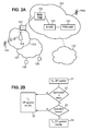
- FIG. 2-A illustrates a mobile network according to one embodiment of the present invention.
- This mobile network corresponds to the network illustrated in reference to figure 1 .
- a routing module 201 is included between the home network 106 and the core network 105 in order to carry out the steps of the method according to one embodiment.
- This routing module 201 is able to received IP packets from the home network 106 on uplink, and from the core network on downlink. For all IP packets transiting through it, it is able to decide if a local routing is required or not according to a mechanism of the present invention.
- the routing module is in charge of updating a table storing an association of a quintuplet and downlink and uplink bearers which correspond to this quintuplet, for a given communication.
- Figure 2-B illustrates the main steps performed by a method of IP packet routing in a mobile network according to one embodiment of the present invention.
- a packet is associated to a quintuplet indicating a source IP address and IP port, a destination IP address and IP port and an indication relative to the used transport protocol.
- the routing module 201 when the routing module 201 receives an IP packet from the home Node B, meaning on uplink, it is able to take a routing decision based on information stored in its table.
- a step 22 it checks if the quintuplet associated to the received packet corresponds to an existing entry in the table, meaning if this quintuplet is already stored in this table. If it is the case, it checks if a downlink bearer is already associated to this quintuplet in the table, at a step 23. If these two checks are positive, at a step 24, the received packet is then transmitted through the downlink bearer indicated in the table in association to the considered quintuplet. If at least one of these both checks is negative, at a step 25, the received packet is transmitted to the core network (or CN).
- Radio bearer between UE and home NodeB and S1 bearer from the home NodeB towards the core network It is planned to use Radio bearer between UE and home NodeB and S1 bearer from the home NodeB towards the core network.
- the home NodeB corresponds to a mapping procedure between radio bearer and S1 bearer, as it will be detailed in some following sections.
- the routing module is located between the mapping procedure of the home NodeB and the Core Network. Consequently, the routing module manipulates only one type of bearer which is S1 bearer.
- Figure 3 illustrates architecture of a mobile network in detail, wherein one embodiment of the present invention can be applied.
- a mobile terminal, or UE for 'User Equipment' can access to the core network 105 via a home network 106.
- the home network 106 corresponds to E-UTRAN, for 'Evolved Universal Terrestrial Radio Access Network', which is an access part of the network.
- This type of architecture is based on a data plane for handling data exchange and on a control plane for handling signalling exchange.
- the core network 105 comprises the Mobility Management Entity MME 102, which is a control node in charge of handling mobility and security for mobile terminals (UEs).
- MME 102 is a contact point for the control plane of the UE.
- MME Mobility Management Entity
- the core network comprises also the Serving Gateway (S-GW) 103, which is the contact point for the data plane of the UE.
- S-GW Serving Gateway
- the Serving Gateway can stay the same even if the UE is moving in the access network.
- the core network 105 comprises the PDN Gateway 104, which is a contact point between the mobile network, LTE network, and the Internet network 110.
- the PDN GW 104 is in charge of handling IP addresses.
- the core network can further comprise a Home Subscriber Server 201 (HSS), which is a central node that mainly contains subscription and parameters information for UEs, and a Serving GPRS Support Node (SGSN) 202, which is in charge of handling data exchange with 3G and GSM networks.
- HSS Home Subscriber Server
- SGSN Serving GPRS Support Node
- This core network can comprise too a Policy and Charging Rules Function 203 (PCRF) in charge of charging sessions handled in this network.
- PCRF Policy and Charging Rules Function
- a routing module 201 is adapted to be an interface to S1 bearer interfaces on one side, and to at least one home NodeB of a home network on the other side.
- the home network part can contain several home NodeBs.
- Figure 4 illustrates an E-UTRAN network 106 comprising three home NodeBs 101-A, 101-B and 101-C.
- the home NodeB 101-A and 101-B are linked to an MME 102-A, and the home NodeB 101-B and 101-C are linked to an MME 102-B.
- Home NodeBs do not implement links of type X2, unlike NodeBs.
- a plurality of bearers is defined in order to support transmission through the network.
- FIG. 5 illustrates in detail different bearers which can be used according to one embodiment of the present invention.
- An end-to-end service between two distant mobile terminals is based on an EPS bearer 41, between UE 100 and the P-GW 104, and an External Bearer 42, between P-GW 104 and the other mobile terminal UE 100.
- the EPS bearer 41 is composed of a bearer E-RAB (for 'Evolved Radio Access Bearer') 43 between the UE 100 and the S GW 202, and of a bearer S5/S8 bearer 44, between the S-GW 202 and the P-GW 104.
- E-RAB for 'Evolved Radio Access Bearer'
- the E-RAB bearer 43 is composed of a Radio bearer 46 between the UE 100 and the home NodeB 101, and of a S1 bearer 45 between the home NodeB and the S-GW 202.
- a default bearer is created. It is also possible to create some additional dedicated bearers at this step.
- Figure 6 illustrates the different protocol stacks in LTE architecture.
- the protocol stack at UE level comprises:
- the protocol stack at a home NodeB comprises:
- the protocol stack at a Serving GateWay corresponds to the layers 614, 613, 612 and 611.
- the protocol stack at a PDN GW corresponds to these layers also, with more up layer IP.
- source and destination IP addresses are respectively the IP address of the source and destination UE. These addresses are allocated by the Core network (or 'EPC' for Evolved Packet Core) during bearer activation step. However, looking addresses is not sufficient since UEs may support different applications with respective data flows transported over different bearers having a same IP address as end points.
- the routing module 201 is in charge of receiving IP packets on S1 bearer and in charge of deciding to forward them towards the core network or to route them towards to the home network by going through the mapping procedure 701 again.
- the routing module handles a table TAB like the following for example:
- this table is adapted to associate on one hand the quintuplet of IP packet information and on the other hand the uplink S1 bearer which is stored through its identifier S1EP_UL_ID for 'S1 End Point UpLink IDentifier' and the downlink S1 bearer through its identifier S1EP_DL_ID for 'S1 End Point DownLink IDentifier'.
- the field S1EP_UL_ID can be advantageously filled for a given quintuplet when said quintuplet is added in the table for the first time, on reception of the first packet of a given connection on uplink.
- the field S1EP_DL_ID can be advantageously filled for a given quintuplet upon reception of the first packet of a connection on downlink, when the entry of said quintuplet already exists in the table.
- this field is updated only when a first packet for the same connection has been already received on uplink. Indeed, in this condition, it means that both UEs of this connection is located in the home network of the routing module and then one embodiment of the present invention can be applied.
- the routing module 201 can monitor applicative IP packets; it can track on uplink first packets of TCP connections and UDP flows, and it can associate ports and addresses to the S1 bearer identifier on which they are transported.
- the term 'connection' corresponds to a TCP connection or a UDP flow.
- Each connection is identified by a quintuplet that contains the transport protocol, the source and destination addresses, the source and destination ports.
- a quintuplet that contains the transport protocol, the source and destination addresses, the source and destination ports.
- it is planned to monitor the received applicative IP packets. Then, according to the type of packets and their direction, either uplink or downlink, the associated quintuplet is extracted from the IP packet, and a lookup is performed in the table in order to determine if this quintuplet is already stored or if it has to be stored.
- uplink data packets are forwarded to the core network through their associated S1 bearer identifier.
- 'by default' means that there is no downlink bearer associated to the quintuplet of a received packet on uplink.
- the quintuplet associated to this connection is stored in the table in association with the S1 bearer uplink identifier, and the first IP packet received on uplink are forwarded towards the core network in order to be routed at the core network level. Indeed, until the first data packet is received from the core network on downlink, the routing module 201 does not know the S1 downlink bearer which is associated to this connection. Thus, at least the first data packet received from a UE of the home network to a UE of the same home network is forwarded to the core network.
- the core network performs a routing, as planned in the prior art and forwards this data packet to the same home network towards the UE which is the recipient of this packet.
- this routing is performed at the core network level, the data packet is associated to a S1 downlink bearer. Consequently, the routing module 201 receives this downlink data packet in association to the S1 bearer downlink identifier. The routing module can then detect that this connection is already known by checking if the corresponding entry already exists in the table, on the basis of the quintuplet of the received packet. Then, it can store the S1 bearer identifier in association with the quintuplet as an associated downlink bearer.
- the routing module is able to route locally the data packets received from the UE towards its recipient based on the table indicating an association between the quintuplet of the connection and the S1 bearer downlink identifier.
- this table is addressed by using a quintuplet, each entry of the table corresponding to a quintuplet.
- S1 Bearer end points can be identified by the IP address of a GTP-U tunnel end point, and a Tunnel End point Identifier (TEID).
- the S1 End Point Identifier (S1EP-ID) can correspond to the couple [IP Address, TEID].
- the end point corresponds to the home NodeB
- the end point corresponds to the S-GW.
- the End point IP address can be found easily in the destination IP address field of the GTP-U packets.
- TEID is located in GTP-U header. By using this couple instead of just using TEID, the routing module mechanism can support multiple home NodeBs connected through a single Home NodeB Data Concentrator to several different S-GWs.
- S1EP-ID is here different from the S1 Bearer Identifier used in the LTE signalling.
- S1EP-ID is an identifier allocated for each different GTP-U endpoint. Consequently, for a single bidirectional S1 bearer, there can be two different S1EP-IDs, one for each direction.
- Figure 8 illustrates one embodiment of the present invention for UDP protocol.
- step 81 the direction of a received data packet is determined.
- step 82 Upon reception of a data packet on uplink, at step 82, a lookup is performed in the table based on the quintuplet :
- step 84 a new record is inserted in the table and is filled with the quintuplet. Moreover, the S1EP_UL_ID field of the table is filled with the identifier of the S1 bearer on which the packet is received. Then, the received data packet is forwarded to the core network at the step 86.
- the S1EP_UL_ID field of the table is compared with the S1 bearer on which the packet is received. If they are different or if S1EP_DL_ID field is not yet filled in the table, the received packet is forwarded to the core network 86 and S1EP_UL_ID field is overwritten if necessary. Otherwise, at step 88, the received packet is forwarded to the downlink S1 bearer indicated in the field S1EP ⁇ _DL_ID of the table in association to the considered entry. This last case corresponds to the case where at least one packet was already received from the core network on downlink for this connection.
- a lookup 83 is performed in the table based on the quintuplet:
- the S1EP_DL_ID field of the corresponding entry in the table is updated at step 88 with the S1 bearer identifier of the S1 bearer on which the data packet is received.
- the received data packet is then forwarded to the HAN at step 88.
- Figure 9 illustrates one embodiment of the present invention for TCP protocol.
- a new entry is recorded in the table when a new uplink connection is detected based on a control of the quintuplet. This can be done by detecting a TCP initialisation sequence like the following sequence of packets:
- connection can be removed from the table when a connection is closed. It can be detected on a TCP close sequence like the following sequence of packets:
- S1EP_UL_ID field can be filled with the identifier of the S1 bearer of the connection on uplink.
- S1EP_DL_ID field can be left blank until reception of the first packet on downlink corresponding to an existing entry in the table for this connection.
- step 901 when a packet is received, at step 901, the TCP flag is checked. If the received packet is a SYN packet, the direction is checked at step 902. For an uplink packet, at step 905, a lookup is performed in the table using the quintuplet:
- step 906 a new entry is added in the table filled with the quintuplet of the received packet.
- the S1EP_UL_ID field is filled with the identifier of the S1 bearer on which the packet is received. If the lookup succeeds, at step 907, the S1EP_UL_ID field is overwritten with the identifier of the S1 bearer on which the packet is received. Then, at step 908, the received packet is forwarded to the core network.
- step 902 If at step 902, the packet is received on downlink, a lookup is performed in the table using the quintuplet:
- the S1EP_DL_ID field of the corresponding entry in the table is updated with the identifier of the S1 bearer on which the packet is received.
- the received packet is detected as being a FIN or RST TCP packet, a lookup is then performed in the table using the quintuplet of the received packet at step 903:
- the lookup succeeds, the corresponding entry is removed from the table at step 912 and the received packet is forwarded to the core network at step 913.
- the received packet is another type of TCP packet
- the direction of this packet is checked. If the packet is received on downlink, it is forwarded to the home network at step 917.
- the S1EP_UL_ID field stored in association to the considered quintuplet is compared with the S1 bearer indicated in the received packet. If the S1 bearer of the received packet is different from the S1EP_UL_ID field or if S1EP_DL_ID is blank, the packet is forwarded to the core network.
- the received packet is forwarded to the downlink S1 bearer indicated by S1EP_DL_ID field of the table at the entry corresponding to the considered quintuplet.
- this step consists in overwriting GTP-U destination IP address and TEID fields with S1EP_DL_ID, and forwarding it to the home NodeB. If the initial lookup fails, the packet is forwarded to the core network.
- a cleaning procedure can be applied to the table in order to maintain only the active connections.
- a cleaning procedure based on the type of packets TCP can be advantageously applied to clean the table in case of TCP connection.
- the following cleaning procedure can be applied to all types of IP connection. It could be planned to handle a new field per entry in the table: Time field.
- Time field In one embodiment, when a new entry is added into the table, the Time field is filled with the current time. This field is updated upon each successful lookup on the corresponding entry, meaning each time a packet belonging to the connection is received and forwarded either on uplink or on downlink.
- a background mechanism can be in charge of removing old entries corresponding to inactive connections, meaning connections where there is no more traffic. This procedure can be advantageously applied to UDP flows and TCP connections, particularly when the TCP connections are not cleanly closed by FIN or RST packets.
- the mobile core network can be informed about the proposed mechanism. Indeed, only the data plane could be impacted and signalling procedure used to establish bearers can be kept unchanged. In this condition, the core network could continue to reserve resource for the locally switched traffic, in particular for services that require a Guarantied Bit Rate (GBR). So, it may be interesting to introduce signalling messages to inform the core network that local data traffic is locally switched and not sent through the core network.
- GLR Guarantied Bit Rate
- a ⁇ LOCAL_ROUTING_REQUEST' message could be sent by the routing module to inform the core network about a local routing for a given connection.
- Such a message could be a 'LOCAL_ROUTiNG_RESPONSE' message.
- the core network can enable or disable a local routing for a given connection.
- This core network control could be advantageous for accounting or traffic control purpose notably.
- the routing module sends to the core network a message LOCAL_ROUTING_REQUEST, indicating, in the field Enable, the true value when a local routing is detected for a given connection.
- the core network returns a message LOCAL_ROUTING_ RESPONSE that indicates if the local routing can be performed or not in the Enable field. Until a positive LOCAL_ROUTING_RESPONSE message, meaning with Enable field set as true, no local routing is performed and packets belonging to the considered connection are forwarded to the core network, as in the prior art.
- the Home NodeB can send to the core network a LOCAL_ROUTING_REQUEST indicating in the Enable field the false value and the core network acknowledges it by returning to the routing module a LOCAL_ROUTING_RESPONSE indicating an Enable field set at false value.
- a TRAFFIC-STAT field can be inserted in the ⁇ LOCAL_ROUTING_REQUEST' message by the routing module to inform the core network about traffic statistics for a given connection, meaning for a given quintuplet. It can be advantageous for accounting and traffic management in the core network.
- a mechanism of local routing according to one embodiment of the present invention requires few power processing. Moreover, in order to perform a faster implementation, a hash based on this quintuplet can be computed to access the table.
- services with high bandwidth requirement may be deployed between devices in a LTE architecture. Indeed, transmission resources can be saved between home NodeB and Core Network. Those saved resources could be used for other WAN services.
- Figure 10 illustrates a routing module according to one embodiment of the present invention.
- the routing module 201 comprises :
- This routing module comprises also a memory to store the table TAB 704.
- This routing decision unit 10-3 can be further adapted, if the quintuplet associated to the received packet is not already stored in the table with an associated downlink bearer, to decide to forward the received packet to the core network through the uplink bearer associated to the received packet.
- the updating unit 10-2 can be adapted to :
- This routing module can be adapted to receive IP packets from a plurality of home NodeBs each of said IP packets comprising a corresponding GTP-U packet; and adapted to forward received IP packets to any home NodeB of said plurality on the basis of a Tunnel End point Identifier and an IP address indicated in the corresponding GTP-U packet.
Landscapes
- Engineering & Computer Science (AREA)
- Computer Networks & Wireless Communication (AREA)
- Signal Processing (AREA)
- Mobile Radio Communication Systems (AREA)
Priority Applications (1)
| Application Number | Priority Date | Filing Date | Title |
|---|---|---|---|
| EP09306353A EP2341733A1 (fr) | 2009-12-30 | 2009-12-30 | Routage de données locales dans un réseau mobile |
Applications Claiming Priority (1)
| Application Number | Priority Date | Filing Date | Title |
|---|---|---|---|
| EP09306353A EP2341733A1 (fr) | 2009-12-30 | 2009-12-30 | Routage de données locales dans un réseau mobile |
Publications (1)
| Publication Number | Publication Date |
|---|---|
| EP2341733A1 true EP2341733A1 (fr) | 2011-07-06 |
Family
ID=42109866
Family Applications (1)
| Application Number | Title | Priority Date | Filing Date |
|---|---|---|---|
| EP09306353A Withdrawn EP2341733A1 (fr) | 2009-12-30 | 2009-12-30 | Routage de données locales dans un réseau mobile |
Country Status (1)
| Country | Link |
|---|---|
| EP (1) | EP2341733A1 (fr) |
Cited By (2)
| Publication number | Priority date | Publication date | Assignee | Title |
|---|---|---|---|---|
| KR20150045211A (ko) * | 2013-10-18 | 2015-04-28 | 에스케이텔레콤 주식회사 | 무선 통신 시스템에서 베어러를 설정하기 위한 장치 및 이를 위한 방법 |
| KR20150045212A (ko) * | 2013-10-18 | 2015-04-28 | 에스케이텔레콤 주식회사 | 무선 통신 시스템에서 베어러를 설정하기 위한 장치 및 이를 위한 방법 |
Citations (1)
| Publication number | Priority date | Publication date | Assignee | Title |
|---|---|---|---|---|
| WO2009024508A1 (fr) * | 2007-08-17 | 2009-02-26 | Nokia Siemens Networks Oy | Acheminement de paquets dans un réseau de télécommunication |
-
2009
- 2009-12-30 EP EP09306353A patent/EP2341733A1/fr not_active Withdrawn
Patent Citations (1)
| Publication number | Priority date | Publication date | Assignee | Title |
|---|---|---|---|---|
| WO2009024508A1 (fr) * | 2007-08-17 | 2009-02-26 | Nokia Siemens Networks Oy | Acheminement de paquets dans un réseau de télécommunication |
Cited By (2)
| Publication number | Priority date | Publication date | Assignee | Title |
|---|---|---|---|---|
| KR20150045211A (ko) * | 2013-10-18 | 2015-04-28 | 에스케이텔레콤 주식회사 | 무선 통신 시스템에서 베어러를 설정하기 위한 장치 및 이를 위한 방법 |
| KR20150045212A (ko) * | 2013-10-18 | 2015-04-28 | 에스케이텔레콤 주식회사 | 무선 통신 시스템에서 베어러를 설정하기 위한 장치 및 이를 위한 방법 |
Similar Documents
| Publication | Publication Date | Title |
|---|---|---|
| US8488559B2 (en) | Method and an apparatus for providing route optimisation | |
| CA2761056C (fr) | Procede et appareil configures pour fournir des services de branchement local avec un seul apn | |
| US8391151B2 (en) | Inter-network-nodes flow control | |
| ES2376183T3 (es) | Sistema de comunicación móvil y pasarela de acceso que tiene u-agw (pasarela de acceso del plano de usuario) plurales. | |
| US9998569B2 (en) | Handling multipath transmission control protocol signaling in a communications network | |
| EP2768250A1 (fr) | Procédé et appareil permettant de recevoir des informations provenant d'un réseau de communications | |
| US8767728B2 (en) | Tunnel gateway managed caching architecture | |
| US20120314688A1 (en) | Method for routing traffic within a network and a network | |
| EP2286615A1 (fr) | Réacheminement de données durant un transfert dans une cellule à liaison terrestre autonome | |
| US9877258B2 (en) | Method and device for transferring data traffic | |
| JP5220882B2 (ja) | 少なくとも1つの端末の移動ネットワークにおけるハンドオーバをハンドリングするための方法、並びに、ルーティングモジュール、ホームノードb、ホームネットワーク、及び移動ネットワーク | |
| US20130242918A1 (en) | Method for providing a local traffic shortcut in a packet-oriented mobile communication network | |
| WO2006097031A1 (fr) | Procede de transmission de message dans le reseau du protocole internet mobile | |
| EP2724563B1 (fr) | Mise en antémémoire sur une interface entre un réseau d'accès radio et un réseau central | |
| EP2306676B1 (fr) | Accès à un réseau IP à partir d'un réseau mobile | |
| EP2341733A1 (fr) | Routage de données locales dans un réseau mobile | |
| EP2020783A1 (fr) | Système de commande de communication mobile | |
| WO2014101525A1 (fr) | Procédé et dispositif pour accomplir un maintien actif d'une traduction d'adresse réseau | |
| KR100852591B1 (ko) | 직접 전달 경로를 이용한 통신 장치 및 그 방법 | |
| EP2306759A1 (fr) | Accès distant à un LAN |
Legal Events
| Date | Code | Title | Description |
|---|---|---|---|
| PUAI | Public reference made under article 153(3) epc to a published international application that has entered the european phase |
Free format text: ORIGINAL CODE: 0009012 |
|
| AK | Designated contracting states |
Kind code of ref document: A1 Designated state(s): AT BE BG CH CY CZ DE DK EE ES FI FR GB GR HR HU IE IS IT LI LT LU LV MC MK MT NL NO PL PT RO SE SI SK SM TR |
|
| AX | Request for extension of the european patent |
Extension state: AL BA RS |
|
| STAA | Information on the status of an ep patent application or granted ep patent |
Free format text: STATUS: THE APPLICATION IS DEEMED TO BE WITHDRAWN |
|
| 18D | Application deemed to be withdrawn |
Effective date: 20120110 |