EP2341320A2 - Resistive position sensor - Google Patents
Resistive position sensor Download PDFInfo
- Publication number
- EP2341320A2 EP2341320A2 EP10252130A EP10252130A EP2341320A2 EP 2341320 A2 EP2341320 A2 EP 2341320A2 EP 10252130 A EP10252130 A EP 10252130A EP 10252130 A EP10252130 A EP 10252130A EP 2341320 A2 EP2341320 A2 EP 2341320A2
- Authority
- EP
- European Patent Office
- Prior art keywords
- sensing device
- flexible member
- base
- output element
- positions
- Prior art date
- Legal status (The legal status is an assumption and is not a legal conclusion. Google has not performed a legal analysis and makes no representation as to the accuracy of the status listed.)
- Granted
Links
Images

Classifications
-
- G—PHYSICS
- G01—MEASURING; TESTING
- G01D—MEASURING NOT SPECIALLY ADAPTED FOR A SPECIFIC VARIABLE; ARRANGEMENTS FOR MEASURING TWO OR MORE VARIABLES NOT COVERED IN A SINGLE OTHER SUBCLASS; TARIFF METERING APPARATUS; MEASURING OR TESTING NOT OTHERWISE PROVIDED FOR
- G01D5/00—Mechanical means for transferring the output of a sensing member; Means for converting the output of a sensing member to another variable where the form or nature of the sensing member does not constrain the means for converting; Transducers not specially adapted for a specific variable
- G01D5/12—Mechanical means for transferring the output of a sensing member; Means for converting the output of a sensing member to another variable where the form or nature of the sensing member does not constrain the means for converting; Transducers not specially adapted for a specific variable using electric or magnetic means
- G01D5/14—Mechanical means for transferring the output of a sensing member; Means for converting the output of a sensing member to another variable where the form or nature of the sensing member does not constrain the means for converting; Transducers not specially adapted for a specific variable using electric or magnetic means influencing the magnitude of a current or voltage
- G01D5/16—Mechanical means for transferring the output of a sensing member; Means for converting the output of a sensing member to another variable where the form or nature of the sensing member does not constrain the means for converting; Transducers not specially adapted for a specific variable using electric or magnetic means influencing the magnitude of a current or voltage by varying resistance
-
- G—PHYSICS
- G01—MEASURING; TESTING
- G01D—MEASURING NOT SPECIALLY ADAPTED FOR A SPECIFIC VARIABLE; ARRANGEMENTS FOR MEASURING TWO OR MORE VARIABLES NOT COVERED IN A SINGLE OTHER SUBCLASS; TARIFF METERING APPARATUS; MEASURING OR TESTING NOT OTHERWISE PROVIDED FOR
- G01D5/00—Mechanical means for transferring the output of a sensing member; Means for converting the output of a sensing member to another variable where the form or nature of the sensing member does not constrain the means for converting; Transducers not specially adapted for a specific variable
- G01D5/12—Mechanical means for transferring the output of a sensing member; Means for converting the output of a sensing member to another variable where the form or nature of the sensing member does not constrain the means for converting; Transducers not specially adapted for a specific variable using electric or magnetic means
- G01D5/14—Mechanical means for transferring the output of a sensing member; Means for converting the output of a sensing member to another variable where the form or nature of the sensing member does not constrain the means for converting; Transducers not specially adapted for a specific variable using electric or magnetic means influencing the magnitude of a current or voltage
- G01D5/18—Mechanical means for transferring the output of a sensing member; Means for converting the output of a sensing member to another variable where the form or nature of the sensing member does not constrain the means for converting; Transducers not specially adapted for a specific variable using electric or magnetic means influencing the magnitude of a current or voltage by varying effective impedance of discharge tubes or semiconductor devices
- G01D5/183—Sensing rotation or linear movement using strain, force or pressure sensors
- G01D5/185—Sensing rotation or linear movement using strain, force or pressure sensors using piezoelectric sensors
-
- H—ELECTRICITY
- H01—ELECTRIC ELEMENTS
- H01H—ELECTRIC SWITCHES; RELAYS; SELECTORS; EMERGENCY PROTECTIVE DEVICES
- H01H5/00—Snap-action arrangements, i.e. in which during a single opening operation or a single closing operation energy is first stored and then released to produce or assist the contact movement
- H01H5/04—Energy stored by deformation of elastic members
- H01H5/30—Energy stored by deformation of elastic members by buckling of disc springs
Definitions
- This disclosure relates to a sensing device that uses a mechanical snap mechanism and a resistive sensing element.
- a wide variety of sensing devices are used to perform, for example, position sensing.
- position sensing When simple, low cost position sensing is desired, a position indicating electrical switch is often used. Switches can exhibit poor reliability in typical aerospace applications, particularly due to sensitivity to contamination of electrical contacts and deterioration within the switch from vibration. Aerospace applications in particular demand reliable switch operation. Continuously monitoring health of the switch contacts is impractical since electrical switches typically have make/break contacts. Thus, switch failures often occur without any prior warning.
- a sensing device includes a bistable snap mechanism having a snap element operatively connected to an input element and an output element.
- the snap element has two discrete positions that provide the output element in one of first and second positions.
- a resistive sensing element includes a flexible member operatively connected to the output element and is configured to deflect in response to movement of the output element between the first and second positions.
- a resistor is mounted on the flexible member and is configured to provide a variable resistance based upon deflection of the flexible member.
- the resistive sensing element includes a generally circular base providing an opening.
- the flexible member extends from the base into the opening and is configured to deflect relative to the base.
- a piezoresistor is mounted on the flexible member and is configured to provide a variable resistance based upon deflection of the flexible member.
- An example method of sensing an input includes receiving an input.
- the output element moves in response to the input.
- the flexible member deflects in response to the output element moving, and the resistance of a resistor varies.
- a signal is provided based upon the resistance that corresponds to an input state.
- a sensing device 10 is illustrated in Figure 1 and includes a housing 12 fixedly mounted to a structure 14 in one example.
- the sensing device 10 includes an input element 16 that receives an input for which it is desirable to determine an input state, which may be force, pressure or temperature.
- the input element 16 cooperates with an output element 18, which is movable relative to the housing 12 in the example.
- the output element 18 is operatively connected to a resistive sensing element 20, which includes a flexible member 22 that cooperates with the output element 18.
- the output element 18 engages the flexible member 22 in one example.
- the input state is transmitted to the resistive sensing element 20 by the output element 18 via the input element 16.
- the resistive sensing element 20 is arranged within a cavity 13 in the housing 12 and includes a generally circular base 24, for example, that provides an opening 26.
- the base 24 is securely retained relative to the housing 12, and the flexible member 22 deflects relative to the base 24 in response to axial movement of the output element 18, for example, between first and second positions P1, P2 ( Figs. 3-5 ).
- a spacer 42 is arranged between the resistive sensing element 20 and a retainer 44, which is secured to the housing 12 at a threaded interface 48.
- a cap 46 seals the cavity 13 to prevent debris from penetrating the sensing device 10.
- the resistive sensing element 20 includes one or more strain gauge resistors 28 mounted on the flexible member 22 such that the resistance of the resistor 28 varies as the flexible member 22 is deflected.
- the flexible member 22 can be protected from overstress with a mechanical stop to limit its deflection.
- the resistor 28 is provided in a wheatstone bridge 34.
- An example wheatstone bridge includes four resistors, and a measured voltage is indicative of a resistance of the resistor 28. The resistance varies with the deflection of the flexible member 22. The measured voltage is indicative of the deflected position D of the flexible member 22. Any number of the four resistors 28 may be active, or variable, and the remaining resistors 28 may be fixed, or constant.
- a pair of piezoresistors 28 is provided on each of the opposing sides of the flexible member 22. Providing one pair of piezoresistors 28 in tension and another pair of piezoresistors in compression provides better sensitivity, if desired.
- a housing 32 is provided on the resistive sensing element 20.
- Element leads 30 are provided from the resistors 28 to connections within the housing 32, for example, that are configured to provide the wheatstone bridge 34.
- the element leads 30 are supported on the base 24.
- Power input leads 36 and voltage output leads 38 connected to the wheatstone bridge 34 extend from the housing 32 to terminals 40.
- a power source 37 provides power to the wheatstone bridge 34 through the power input leads 36.
- a controller 39 measures the voltage signal across the wheatstone bridge 34 at the voltage output leads 38, which corresponds to the resistance indicative of the deflected position D which in turn corresponds to the input state. In this manner, a continuous resistance signal is available. The resistance signal can be monitored at any time by measuring the voltage to determine the health of the sensing device 10.
- a snap mechanism 50 (schematically shown in Figure 2 ) may be provided between the input element 16 and the output element 18 to provide a bistable switch having two discrete positions.
- a first position P1 is indicative of the input state being below a given threshold, or "off,” and the second position P2 is indicative of the input state being at or above the threshold, or "on.”
- the snap mechanism 50 maintains a positive reacting force throughout the operating stroke of the output element 18.
- a disc in the snap mechanism 50 deflects as the input increases until a maximum threshold force is applied to the disc at which point the disc "snaps" over.
- Figure 3 illustrates an example force measurement configuration.
- a stem 56 provides the input element 16 (receiving a force F) and the output element 18.
- a structure 52 supports a snap element 54 connected to the stem 56.
- the snap element 54 which is a flexible disc in one example, has a concave configuration with the stem 56 in the first position P1.
- the snap element 54 is deflected to a convex configuration (dashed line) that moves the stem 56 to the second position P2. Stops 58 limit the travel of the stem 56.
- FIG. 4 illustrates an example pressure measurement configuration.
- a stem 156 is connected to a diaphragm 60 that provides the input element 116 (receiving a pressure P).
- the stem 156 provides the output element 18.
- a structure 152 supports the diaphragm 60 and a snap element 154 that is connected to the stem 156.
- the snap element 154 has a concave configuration with the stem 156 in the first position P1. Upon the pressure P reaching a threshold pressure, the snap element 154 is deflected to a convex configuration (dashed line) that moves the stem 156 to the second position P2. Stops 158 limit the travel of the stem 156.
- Figure 5 illustrates an example temperature measurement configuration.
- a reservoir 62 filled with a material having thermally variable volume provides the input element 116 with the volume change in response to a temperature T.
- the stem 256 cooperates with the material in the reservoir 62 and provides the output element 218.
- a structure 252 supports a snap element 254 connected to the stem 256.
- the snap element 254 has a concave configuration with the stem 256 in the first position P1.
- the snap element 254 is deflected to a convex configuration (dashed line) that moves the stem 256 to the second position P2. Stops 258 limit the travel of the stem 256.
Landscapes
- Physics & Mathematics (AREA)
- General Physics & Mathematics (AREA)
- Measuring Fluid Pressure (AREA)
- Adjustable Resistors (AREA)
- Measurement Of Length, Angles, Or The Like Using Electric Or Magnetic Means (AREA)
- Force Measurement Appropriate To Specific Purposes (AREA)
Abstract
Description
- This disclosure relates to a sensing device that uses a mechanical snap mechanism and a resistive sensing element.
- A wide variety of sensing devices are used to perform, for example, position sensing. When simple, low cost position sensing is desired, a position indicating electrical switch is often used. Switches can exhibit poor reliability in typical aerospace applications, particularly due to sensitivity to contamination of electrical contacts and deterioration within the switch from vibration. Aerospace applications in particular demand reliable switch operation. Continuously monitoring health of the switch contacts is impractical since electrical switches typically have make/break contacts. Thus, switch failures often occur without any prior warning.
- A sensing device is disclosed that includes a bistable snap mechanism having a snap element operatively connected to an input element and an output element. The snap element has two discrete positions that provide the output element in one of first and second positions. A resistive sensing element includes a flexible member operatively connected to the output element and is configured to deflect in response to movement of the output element between the first and second positions. A resistor is mounted on the flexible member and is configured to provide a variable resistance based upon deflection of the flexible member.
- In one example, the resistive sensing element includes a generally circular base providing an opening. The flexible member extends from the base into the opening and is configured to deflect relative to the base. A piezoresistor is mounted on the flexible member and is configured to provide a variable resistance based upon deflection of the flexible member.
- An example method of sensing an input includes receiving an input. The output element moves in response to the input. The flexible member deflects in response to the output element moving, and the resistance of a resistor varies. A signal is provided based upon the resistance that corresponds to an input state.
- The disclosure can be further understood by reference to the following detailed description when considered in connection with the accompanying drawings wherein:
-
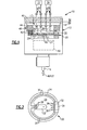
Figure 1 is a cross-sectional view of an example sensing device. -
Figure 2 is an elevational view of a sensing element. -
Figure 3 is a schematic view of an example snap mechanism. -
Figure 4 is a schematic view of another example snap mechanism. -
Figure 5 is a schematic view of yet another example snap mechanism. - A
sensing device 10 is illustrated inFigure 1 and includes ahousing 12 fixedly mounted to astructure 14 in one example. Thesensing device 10 includes aninput element 16 that receives an input for which it is desirable to determine an input state, which may be force, pressure or temperature. Theinput element 16 cooperates with anoutput element 18, which is movable relative to thehousing 12 in the example. - The
output element 18 is operatively connected to aresistive sensing element 20, which includes aflexible member 22 that cooperates with theoutput element 18. Theoutput element 18 engages theflexible member 22 in one example. The input state is transmitted to theresistive sensing element 20 by theoutput element 18 via theinput element 16. Referring toFigure 2 , theresistive sensing element 20 is arranged within acavity 13 in thehousing 12 and includes a generallycircular base 24, for example, that provides anopening 26. Thebase 24 is securely retained relative to thehousing 12, and theflexible member 22 deflects relative to thebase 24 in response to axial movement of theoutput element 18, for example, between first and second positions P1, P2 (Figs. 3-5 ). - In the example, a
spacer 42 is arranged between theresistive sensing element 20 and aretainer 44, which is secured to thehousing 12 at a threadedinterface 48. Acap 46 seals thecavity 13 to prevent debris from penetrating thesensing device 10. - The
resistive sensing element 20 includes one or morestrain gauge resistors 28 mounted on theflexible member 22 such that the resistance of theresistor 28 varies as theflexible member 22 is deflected. Theflexible member 22 can be protected from overstress with a mechanical stop to limit its deflection. Theresistor 28 is provided in awheatstone bridge 34. An example wheatstone bridge includes four resistors, and a measured voltage is indicative of a resistance of theresistor 28. The resistance varies with the deflection of theflexible member 22. The measured voltage is indicative of the deflected position D of theflexible member 22. Any number of the fourresistors 28 may be active, or variable, and theremaining resistors 28 may be fixed, or constant. In one example, a pair ofpiezoresistors 28 is provided on each of the opposing sides of theflexible member 22. Providing one pair ofpiezoresistors 28 in tension and another pair of piezoresistors in compression provides better sensitivity, if desired. - A
housing 32 is provided on theresistive sensing element 20. Element leads 30 are provided from theresistors 28 to connections within thehousing 32, for example, that are configured to provide thewheatstone bridge 34. In one example, the element leads 30 are supported on thebase 24. Power input leads 36 and voltage output leads 38 connected to thewheatstone bridge 34 extend from thehousing 32 toterminals 40. Apower source 37 provides power to thewheatstone bridge 34 through the power input leads 36. Acontroller 39 measures the voltage signal across thewheatstone bridge 34 at the voltage output leads 38, which corresponds to the resistance indicative of the deflected position D which in turn corresponds to the input state. In this manner, a continuous resistance signal is available. The resistance signal can be monitored at any time by measuring the voltage to determine the health of thesensing device 10. - A snap mechanism 50 (schematically shown in
Figure 2 ) may be provided between theinput element 16 and theoutput element 18 to provide a bistable switch having two discrete positions. A first position P1 is indicative of the input state being below a given threshold, or "off," and the second position P2 is indicative of the input state being at or above the threshold, or "on." Thesnap mechanism 50 maintains a positive reacting force throughout the operating stroke of theoutput element 18. A disc in thesnap mechanism 50 deflects as the input increases until a maximum threshold force is applied to the disc at which point the disc "snaps" over. -
Figure 3 illustrates an example force measurement configuration. Astem 56 provides the input element 16 (receiving a force F) and theoutput element 18. Astructure 52 supports asnap element 54 connected to thestem 56. Thesnap element 54, which is a flexible disc in one example, has a concave configuration with thestem 56 in the first position P1. Upon the force F reaching a threshold force, thesnap element 54 is deflected to a convex configuration (dashed line) that moves thestem 56 to the second position P2. Stops 58 limit the travel of thestem 56. -
Figure 4 illustrates an example pressure measurement configuration. Astem 156 is connected to adiaphragm 60 that provides the input element 116 (receiving a pressure P). Thestem 156 provides theoutput element 18. Astructure 152 supports thediaphragm 60 and asnap element 154 that is connected to thestem 156. Thesnap element 154 has a concave configuration with thestem 156 in the first position P1. Upon the pressure P reaching a threshold pressure, thesnap element 154 is deflected to a convex configuration (dashed line) that moves thestem 156 to the second position P2.Stops 158 limit the travel of thestem 156. -
Figure 5 illustrates an example temperature measurement configuration. Areservoir 62 filled with a material having thermally variable volume provides theinput element 116 with the volume change in response to a temperature T. Thestem 256 cooperates with the material in thereservoir 62 and provides theoutput element 218. Astructure 252 supports asnap element 254 connected to thestem 256. Thesnap element 254 has a concave configuration with thestem 256 in the first position P1. Upon the volume of the material expanding a sufficient amount indicative of a threshold temperature, thesnap element 254 is deflected to a convex configuration (dashed line) that moves thestem 256 to the second position P2.Stops 258 limit the travel of thestem 256. - Although example embodiments have been disclosed, a worker of ordinary skill in this art would recognize that certain modifications would come within the scope of the claims. For that reason, the following claims should be studied to determine their true scope and content.
- Certain aspects of this invention which are not presently claimed but which may form the subject of a divisional application are set out in the following clauses:
- 1. A resistive sensing element comprising:
- a generally circular base providing an opening, and a flexible member extending from the base into the opening and configured to deflect relative to the base, a piezoresistor mounted on the flexible member and configured to provide a variable resistance based upon deflection of the flexible member.
- 2. The resistive sensing element according to
clause 1, the flexible member includes opposing first and second sides, and first and second piezoresistor are respectively mounted on the first and second sides. - 3. The resistive sensing element according to clause 2, wherein in third and fourth piezoresistors are respectively mounted on the first and second sides.
- 4. The resistive sensing element according to
clause 1, comprising a wheatstone bridge including the piezoresistor. - 5. The resistive sensing element according to clause 4, comprising a housing supported on the base, the wheatstone bridge including connections provided in the housing.
- 6. The resistive sensing element according to clause 5, wherein element leads electrically connect the piezoresistor and the wheatstone bridge, the element leads supported on the base.
- 7. A method of sensing an input comprising:
- receiving an input;
- moving an output element in response to the input;
- deflecting a flexible member in response to the output element moving;
- varying the resistance of a resistor mounted on the flexible member; and
- providing a signal based upon the resistance that corresponds to an input state.
- 8. The method according to clause 7, wherein the input is a temperature.
- 9. The method according to clause 7, wherein the input is a force.
- 10. The method according to clause 7, wherein the input is a pressure.
Claims (15)
- A sensing device (10) comprising:a bistable snap mechanism (50, 150, 250) including a snap element (54, 154, 254) operatively connected to an input element (16, 116) and an output element (18), the snap element having two discrete positions that provides the output element in one of first and second positions (P1, P2);a resistive sensing element (20) including a flexible member (22) operatively connected to the output element and configured to deflect in response to movement of the output element between the first and second positions, a resistor (28) mounted on the flexible member and configured to provide a variable resistance based upon deflection of the flexible member.
- The sensing device according to claim 1, wherein the snap element includes a flexible disc (54) configured to move between concave and convex configurations.
- The sensing device according to claim 2, wherein the bistable snap mechanism includes a stem (56) connected to the flexible disc, the stem providing the output element.
- The sensing device according to claim 3, wherein the stem is configured to move along an axis between the first and second positions (P1, P2) in response to the flexible disc moving between the concave and convex configurations.
- The sensing device according to claim 3 or 4, wherein the first and second positions respectively correspond to the flexible disc in the concave and convex positions, the bistable snap mechanism having a biasing member operatively connected to the flexible disc and configured to return the output element to the first position.
- The sensing device according to any preceding claim, wherein the input element includes a diaphragm.
- The sensing device according to any preceding claim, wherein the input element includes a material (216) with thermally variable volume.
- The sensing device according to any preceding claim, wherein the resistive sensing element includes a wheatstone bridge that includes the resistor.
- The sensing device according to any preceding claim, comprising a housing (12) supporting the bistable snap mechanism and the resistive sensing element.
- The sensing device according to claim 9, wherein the resistive sensing element includes a base (24) secured to the housing and the flexible member extending from the base and engaging the output element.
- The sensing device according to claim 10, the base being generally circular and providing an opening, the flexible member extending from the base into the opening and configured to deflect relative to the base, the resistive element being a piezoresistor mounted on the flexible member and configured to provide a variable resistance based upon deflection of the flexible member.
- The sensing device according to claim 11, wherein the flexible member includes opposing first and second sides, and first and second piezoresistors are respectively mounted on the first and second sides.
- The sensing device according to claim 12, wherein third and fourth piezoresistors are respectively mounted on the first and second sides.
- The sensing device according to claim 11, 12 or 13, comprising a wheatstone bridge including the piezoresistor, and housing supported on the base, the wheatstone bridge including connections provided in the housing.
- The sensing device according to claim 15, wherein element leads electrically connect the piezoresistor and the wheatstone bridge, the element leads being supported on the base.
Applications Claiming Priority (1)
| Application Number | Priority Date | Filing Date | Title |
|---|---|---|---|
| US12/639,104 US8154175B2 (en) | 2009-12-16 | 2009-12-16 | Sensing device |
Publications (3)
| Publication Number | Publication Date |
|---|---|
| EP2341320A2 true EP2341320A2 (en) | 2011-07-06 |
| EP2341320A3 EP2341320A3 (en) | 2015-02-18 |
| EP2341320B1 EP2341320B1 (en) | 2020-03-25 |
Family
ID=43857650
Family Applications (1)
| Application Number | Title | Priority Date | Filing Date |
|---|---|---|---|
| EP10252130.9A Active EP2341320B1 (en) | 2009-12-16 | 2010-12-16 | Resistive position sensor |
Country Status (2)
| Country | Link |
|---|---|
| US (1) | US8154175B2 (en) |
| EP (1) | EP2341320B1 (en) |
Families Citing this family (3)
| Publication number | Priority date | Publication date | Assignee | Title |
|---|---|---|---|---|
| US7520860B2 (en) * | 2005-04-13 | 2009-04-21 | Marie G. Johnson | Detection of coronary artery disease using an electronic stethoscope |
| CN102762152A (en) * | 2009-12-08 | 2012-10-31 | Aum心血管股份有限公司 | Systems and methods for detecting cardiovascular disease |
| US9551754B2 (en) | 2015-06-05 | 2017-01-24 | Circor Aerospace, Inc. | Test device for kinetic switches and method of testing kinetic switches |
Family Cites Families (22)
| Publication number | Priority date | Publication date | Assignee | Title |
|---|---|---|---|---|
| FR2040846A5 (en) * | 1969-04-15 | 1971-01-22 | Sadar | |
| DE7531355U (en) * | 1975-10-03 | 1978-04-27 | Inter Control Hermann Koehler Elektrik Gmbh & Co Kg, 8500 Nuernberg | Resettable temperature limiter |
| GB2114810B (en) * | 1982-02-11 | 1985-11-27 | Itt Ind Ltd | Electro mechanical position sensor |
| US5270595A (en) | 1984-10-02 | 1993-12-14 | United Technologies Corporation | Dynamic thermal compensation for a magnetostrictive actuator |
| US5165289A (en) * | 1990-07-10 | 1992-11-24 | Johnson Service Company | Resonant mechanical sensor |
| IT1262407B (en) | 1993-09-06 | 1996-06-19 | Finmeccanica Spa | INSTRUMENTATION USING INTEGRATED OPTIC COMPONENTS FOR DIAGNOSTICS OF PARTS WITH FIBER OPTIC SENSORS INCLUDED OR FIXED ON THE SURFACE. |
| JP3003974B2 (en) | 1993-11-22 | 2000-01-31 | 富士通株式会社 | Voltage / displacement detection probe and voltage / displacement measuring device using the same |
| US5545007A (en) | 1994-11-25 | 1996-08-13 | United Technologies Corp. | Engine blade clearance control system with piezoelectric actuator |
| US6104119A (en) | 1998-03-06 | 2000-08-15 | Motorola, Inc. | Piezoelectric switch |
| US6450006B1 (en) | 1999-05-26 | 2002-09-17 | Steven J. Dougherty | Method and apparatus for control of linear actuation force |
| US6356007B1 (en) | 2000-05-30 | 2002-03-12 | Young & Franklin, Inc. | Bi-stable snap over actuator |
| US6360615B1 (en) | 2000-06-06 | 2002-03-26 | Technoskin, Llc | Wearable effect-emitting strain gauge device |
| US6822584B2 (en) * | 2001-05-17 | 2004-11-23 | Hewlett-Packard Development Company, L.P. | Morse code key using a strain gauge |
| US7093498B2 (en) | 2003-09-30 | 2006-08-22 | Rockwell Automation Technologies, Inc. | Microelectromechanical strain gauge with frequency detector |
| KR100524343B1 (en) * | 2003-10-30 | 2005-10-28 | 한국과학기술연구원 | Generator for use with a micro system having dual diaphragms |
| WO2005058133A2 (en) * | 2003-12-11 | 2005-06-30 | Proteus Biomedical, Inc. | Implantable pressure sensors |
| US7318007B2 (en) | 2003-12-31 | 2008-01-08 | United Technologies Corporation | Real time gear box health management system and method of using the same |
| SG151331A1 (en) * | 2004-04-07 | 2009-04-30 | Wyeth Corp | Crystalline polymorph of a bazedoxifene acetate |
| US7116036B2 (en) * | 2004-08-02 | 2006-10-03 | General Electric Company | Energy harvesting system, apparatus and method |
| US7616013B2 (en) * | 2004-11-11 | 2009-11-10 | Brigham Young University | Micromechanical positional state sensing apparatus method and system |
| US7508040B2 (en) * | 2006-06-05 | 2009-03-24 | Hewlett-Packard Development Company, L.P. | Micro electrical mechanical systems pressure sensor |
| US7436104B2 (en) * | 2006-10-20 | 2008-10-14 | The Boeing Company | Non-linear piezoelectric mechanical-to-electrical generator system and method |
-
2009
- 2009-12-16 US US12/639,104 patent/US8154175B2/en active Active
-
2010
- 2010-12-16 EP EP10252130.9A patent/EP2341320B1/en active Active
Non-Patent Citations (1)
| Title |
|---|
| None |
Also Published As
| Publication number | Publication date |
|---|---|
| EP2341320B1 (en) | 2020-03-25 |
| US20110139594A1 (en) | 2011-06-16 |
| EP2341320A3 (en) | 2015-02-18 |
| US8154175B2 (en) | 2012-04-10 |
Similar Documents
| Publication | Publication Date | Title |
|---|---|---|
| CN102012288B (en) | Composite micro-electro-mechanical system (MEMS) high-temperature resistant ultrahigh-pressure sensor | |
| US7401522B2 (en) | Pressure sensor using compressible sensor body | |
| EP2270455B1 (en) | Force sensor apparatus | |
| US11867712B2 (en) | Gas densimeter | |
| CA2999969C (en) | Pressure transmitter with overpressure protection | |
| CN102016516B (en) | Measuring transducer for process instrumentation, and method for monitoring the condition of the sensor thereof | |
| CN106556484B (en) | Silicon chip pressure sensor capable of bearing high overpressure and having expanded pressure signal output | |
| CN105829850A (en) | Method for operating a pressure transducer and pressure transducer | |
| US20170059436A1 (en) | Temperature-compensated pressure gauge with a switch output | |
| EP2341320B1 (en) | Resistive position sensor | |
| US20180160922A1 (en) | Pressure sensor | |
| US20180172534A1 (en) | Pressure detecting device | |
| CN109103050B (en) | Method for improving precision of gas density relay | |
| CN219641140U (en) | Mechanical low-voltage pressure switch | |
| JPH0712667A (en) | Physical quantity sensor and physical quantity sensor system | |
| KR101078171B1 (en) | Pressure measuring apparatus | |
| US6553840B2 (en) | Linear displacement sensor apparatus | |
| CN201004434Y (en) | Gas density switch using gas compensation | |
| JP6282301B2 (en) | Hydrogen remaining amount sensor | |
| US20250389604A1 (en) | Extended range silicon pressure sensor with improved overpressure response | |
| CN220039515U (en) | Force and temperature measuring composite sensor | |
| EP3748323B1 (en) | Differential pressure transducer | |
| WO2026072424A1 (en) | High output extended-range strain gauge pressure sensor | |
| CN118758467A (en) | Sensors, electronic devices | |
| JPWO2016027472A1 (en) | pressure switch |
Legal Events
| Date | Code | Title | Description |
|---|---|---|---|
| PUAI | Public reference made under article 153(3) epc to a published international application that has entered the european phase |
Free format text: ORIGINAL CODE: 0009012 |
|
| AK | Designated contracting states |
Kind code of ref document: A2 Designated state(s): AL AT BE BG CH CY CZ DE DK EE ES FI FR GB GR HR HU IE IS IT LI LT LU LV MC MK MT NL NO PL PT RO RS SE SI SK SM TR |
|
| AX | Request for extension of the european patent |
Extension state: BA ME |
|
| PUAL | Search report despatched |
Free format text: ORIGINAL CODE: 0009013 |
|
| AK | Designated contracting states |
Kind code of ref document: A3 Designated state(s): AL AT BE BG CH CY CZ DE DK EE ES FI FR GB GR HR HU IE IS IT LI LT LU LV MC MK MT NL NO PL PT RO RS SE SI SK SM TR |
|
| AX | Request for extension of the european patent |
Extension state: BA ME |
|
| RIC1 | Information provided on ipc code assigned before grant |
Ipc: H01H 1/00 20060101ALI20150109BHEP Ipc: G01D 5/16 20060101AFI20150109BHEP |
|
| 17P | Request for examination filed |
Effective date: 20150818 |
|
| RBV | Designated contracting states (corrected) |
Designated state(s): AL AT BE BG CH CY CZ DE DK EE ES FI FR GB GR HR HU IE IS IT LI LT LU LV MC MK MT NL NO PL PT RO RS SE SI SK SM TR |
|
| STAA | Information on the status of an ep patent application or granted ep patent |
Free format text: STATUS: EXAMINATION IS IN PROGRESS |
|
| 17Q | First examination report despatched |
Effective date: 20180607 |
|
| GRAP | Despatch of communication of intention to grant a patent |
Free format text: ORIGINAL CODE: EPIDOSNIGR1 |
|
| STAA | Information on the status of an ep patent application or granted ep patent |
Free format text: STATUS: GRANT OF PATENT IS INTENDED |
|
| INTG | Intention to grant announced |
Effective date: 20191008 |
|
| RAP1 | Party data changed (applicant data changed or rights of an application transferred) |
Owner name: HAMILTON SUNDSTRAND CORPORATION |
|
| GRAS | Grant fee paid |
Free format text: ORIGINAL CODE: EPIDOSNIGR3 |
|
| GRAA | (expected) grant |
Free format text: ORIGINAL CODE: 0009210 |
|
| STAA | Information on the status of an ep patent application or granted ep patent |
Free format text: STATUS: THE PATENT HAS BEEN GRANTED |
|
| AK | Designated contracting states |
Kind code of ref document: B1 Designated state(s): AL AT BE BG CH CY CZ DE DK EE ES FI FR GB GR HR HU IE IS IT LI LT LU LV MC MK MT NL NO PL PT RO RS SE SI SK SM TR |
|
| REG | Reference to a national code |
Ref country code: GB Ref legal event code: FG4D |
|
| REG | Reference to a national code |
Ref country code: AT Ref legal event code: REF Ref document number: 1249077 Country of ref document: AT Kind code of ref document: T Effective date: 20200415 Ref country code: IE Ref legal event code: FG4D |
|
| REG | Reference to a national code |
Ref country code: DE Ref legal event code: R096 Ref document number: 602010063610 Country of ref document: DE |
|
| PG25 | Lapsed in a contracting state [announced via postgrant information from national office to epo] |
Ref country code: RS Free format text: LAPSE BECAUSE OF FAILURE TO SUBMIT A TRANSLATION OF THE DESCRIPTION OR TO PAY THE FEE WITHIN THE PRESCRIBED TIME-LIMIT Effective date: 20200325 Ref country code: NO Free format text: LAPSE BECAUSE OF FAILURE TO SUBMIT A TRANSLATION OF THE DESCRIPTION OR TO PAY THE FEE WITHIN THE PRESCRIBED TIME-LIMIT Effective date: 20200625 Ref country code: FI Free format text: LAPSE BECAUSE OF FAILURE TO SUBMIT A TRANSLATION OF THE DESCRIPTION OR TO PAY THE FEE WITHIN THE PRESCRIBED TIME-LIMIT Effective date: 20200325 |
|
| PG25 | Lapsed in a contracting state [announced via postgrant information from national office to epo] |
Ref country code: HR Free format text: LAPSE BECAUSE OF FAILURE TO SUBMIT A TRANSLATION OF THE DESCRIPTION OR TO PAY THE FEE WITHIN THE PRESCRIBED TIME-LIMIT Effective date: 20200325 Ref country code: LV Free format text: LAPSE BECAUSE OF FAILURE TO SUBMIT A TRANSLATION OF THE DESCRIPTION OR TO PAY THE FEE WITHIN THE PRESCRIBED TIME-LIMIT Effective date: 20200325 Ref country code: SE Free format text: LAPSE BECAUSE OF FAILURE TO SUBMIT A TRANSLATION OF THE DESCRIPTION OR TO PAY THE FEE WITHIN THE PRESCRIBED TIME-LIMIT Effective date: 20200325 Ref country code: BG Free format text: LAPSE BECAUSE OF FAILURE TO SUBMIT A TRANSLATION OF THE DESCRIPTION OR TO PAY THE FEE WITHIN THE PRESCRIBED TIME-LIMIT Effective date: 20200625 Ref country code: GR Free format text: LAPSE BECAUSE OF FAILURE TO SUBMIT A TRANSLATION OF THE DESCRIPTION OR TO PAY THE FEE WITHIN THE PRESCRIBED TIME-LIMIT Effective date: 20200626 |
|
| REG | Reference to a national code |
Ref country code: NL Ref legal event code: MP Effective date: 20200325 |
|
| REG | Reference to a national code |
Ref country code: LT Ref legal event code: MG4D |
|
| PG25 | Lapsed in a contracting state [announced via postgrant information from national office to epo] |
Ref country code: NL Free format text: LAPSE BECAUSE OF FAILURE TO SUBMIT A TRANSLATION OF THE DESCRIPTION OR TO PAY THE FEE WITHIN THE PRESCRIBED TIME-LIMIT Effective date: 20200325 |
|
| PG25 | Lapsed in a contracting state [announced via postgrant information from national office to epo] |
Ref country code: CZ Free format text: LAPSE BECAUSE OF FAILURE TO SUBMIT A TRANSLATION OF THE DESCRIPTION OR TO PAY THE FEE WITHIN THE PRESCRIBED TIME-LIMIT Effective date: 20200325 Ref country code: PT Free format text: LAPSE BECAUSE OF FAILURE TO SUBMIT A TRANSLATION OF THE DESCRIPTION OR TO PAY THE FEE WITHIN THE PRESCRIBED TIME-LIMIT Effective date: 20200818 Ref country code: RO Free format text: LAPSE BECAUSE OF FAILURE TO SUBMIT A TRANSLATION OF THE DESCRIPTION OR TO PAY THE FEE WITHIN THE PRESCRIBED TIME-LIMIT Effective date: 20200325 Ref country code: LT Free format text: LAPSE BECAUSE OF FAILURE TO SUBMIT A TRANSLATION OF THE DESCRIPTION OR TO PAY THE FEE WITHIN THE PRESCRIBED TIME-LIMIT Effective date: 20200325 Ref country code: EE Free format text: LAPSE BECAUSE OF FAILURE TO SUBMIT A TRANSLATION OF THE DESCRIPTION OR TO PAY THE FEE WITHIN THE PRESCRIBED TIME-LIMIT Effective date: 20200325 Ref country code: SM Free format text: LAPSE BECAUSE OF FAILURE TO SUBMIT A TRANSLATION OF THE DESCRIPTION OR TO PAY THE FEE WITHIN THE PRESCRIBED TIME-LIMIT Effective date: 20200325 Ref country code: IS Free format text: LAPSE BECAUSE OF FAILURE TO SUBMIT A TRANSLATION OF THE DESCRIPTION OR TO PAY THE FEE WITHIN THE PRESCRIBED TIME-LIMIT Effective date: 20200725 Ref country code: SK Free format text: LAPSE BECAUSE OF FAILURE TO SUBMIT A TRANSLATION OF THE DESCRIPTION OR TO PAY THE FEE WITHIN THE PRESCRIBED TIME-LIMIT Effective date: 20200325 |
|
| REG | Reference to a national code |
Ref country code: AT Ref legal event code: MK05 Ref document number: 1249077 Country of ref document: AT Kind code of ref document: T Effective date: 20200325 |
|
| REG | Reference to a national code |
Ref country code: DE Ref legal event code: R097 Ref document number: 602010063610 Country of ref document: DE |
|
| PG25 | Lapsed in a contracting state [announced via postgrant information from national office to epo] |
Ref country code: AT Free format text: LAPSE BECAUSE OF FAILURE TO SUBMIT A TRANSLATION OF THE DESCRIPTION OR TO PAY THE FEE WITHIN THE PRESCRIBED TIME-LIMIT Effective date: 20200325 Ref country code: ES Free format text: LAPSE BECAUSE OF FAILURE TO SUBMIT A TRANSLATION OF THE DESCRIPTION OR TO PAY THE FEE WITHIN THE PRESCRIBED TIME-LIMIT Effective date: 20200325 Ref country code: DK Free format text: LAPSE BECAUSE OF FAILURE TO SUBMIT A TRANSLATION OF THE DESCRIPTION OR TO PAY THE FEE WITHIN THE PRESCRIBED TIME-LIMIT Effective date: 20200325 Ref country code: IT Free format text: LAPSE BECAUSE OF FAILURE TO SUBMIT A TRANSLATION OF THE DESCRIPTION OR TO PAY THE FEE WITHIN THE PRESCRIBED TIME-LIMIT Effective date: 20200325 |
|
| PLBE | No opposition filed within time limit |
Free format text: ORIGINAL CODE: 0009261 |
|
| STAA | Information on the status of an ep patent application or granted ep patent |
Free format text: STATUS: NO OPPOSITION FILED WITHIN TIME LIMIT |
|
| PG25 | Lapsed in a contracting state [announced via postgrant information from national office to epo] |
Ref country code: PL Free format text: LAPSE BECAUSE OF FAILURE TO SUBMIT A TRANSLATION OF THE DESCRIPTION OR TO PAY THE FEE WITHIN THE PRESCRIBED TIME-LIMIT Effective date: 20200325 |
|
| 26N | No opposition filed |
Effective date: 20210112 |
|
| PG25 | Lapsed in a contracting state [announced via postgrant information from national office to epo] |
Ref country code: SI Free format text: LAPSE BECAUSE OF FAILURE TO SUBMIT A TRANSLATION OF THE DESCRIPTION OR TO PAY THE FEE WITHIN THE PRESCRIBED TIME-LIMIT Effective date: 20200325 |
|
| REG | Reference to a national code |
Ref country code: CH Ref legal event code: PL |
|
| PG25 | Lapsed in a contracting state [announced via postgrant information from national office to epo] |
Ref country code: MC Free format text: LAPSE BECAUSE OF FAILURE TO SUBMIT A TRANSLATION OF THE DESCRIPTION OR TO PAY THE FEE WITHIN THE PRESCRIBED TIME-LIMIT Effective date: 20200325 |
|
| REG | Reference to a national code |
Ref country code: BE Ref legal event code: MM Effective date: 20201231 |
|
| PG25 | Lapsed in a contracting state [announced via postgrant information from national office to epo] |
Ref country code: LU Free format text: LAPSE BECAUSE OF NON-PAYMENT OF DUE FEES Effective date: 20201216 Ref country code: IE Free format text: LAPSE BECAUSE OF NON-PAYMENT OF DUE FEES Effective date: 20201216 |
|
| PG25 | Lapsed in a contracting state [announced via postgrant information from national office to epo] |
Ref country code: CH Free format text: LAPSE BECAUSE OF NON-PAYMENT OF DUE FEES Effective date: 20201231 Ref country code: LI Free format text: LAPSE BECAUSE OF NON-PAYMENT OF DUE FEES Effective date: 20201231 |
|
| PG25 | Lapsed in a contracting state [announced via postgrant information from national office to epo] |
Ref country code: TR Free format text: LAPSE BECAUSE OF FAILURE TO SUBMIT A TRANSLATION OF THE DESCRIPTION OR TO PAY THE FEE WITHIN THE PRESCRIBED TIME-LIMIT Effective date: 20200325 Ref country code: MT Free format text: LAPSE BECAUSE OF FAILURE TO SUBMIT A TRANSLATION OF THE DESCRIPTION OR TO PAY THE FEE WITHIN THE PRESCRIBED TIME-LIMIT Effective date: 20200325 Ref country code: CY Free format text: LAPSE BECAUSE OF FAILURE TO SUBMIT A TRANSLATION OF THE DESCRIPTION OR TO PAY THE FEE WITHIN THE PRESCRIBED TIME-LIMIT Effective date: 20200325 |
|
| PG25 | Lapsed in a contracting state [announced via postgrant information from national office to epo] |
Ref country code: MK Free format text: LAPSE BECAUSE OF FAILURE TO SUBMIT A TRANSLATION OF THE DESCRIPTION OR TO PAY THE FEE WITHIN THE PRESCRIBED TIME-LIMIT Effective date: 20200325 Ref country code: AL Free format text: LAPSE BECAUSE OF FAILURE TO SUBMIT A TRANSLATION OF THE DESCRIPTION OR TO PAY THE FEE WITHIN THE PRESCRIBED TIME-LIMIT Effective date: 20200325 |
|
| PG25 | Lapsed in a contracting state [announced via postgrant information from national office to epo] |
Ref country code: BE Free format text: LAPSE BECAUSE OF NON-PAYMENT OF DUE FEES Effective date: 20201231 |
|
| P01 | Opt-out of the competence of the unified patent court (upc) registered |
Effective date: 20230522 |
|
| PGFP | Annual fee paid to national office [announced via postgrant information from national office to epo] |
Ref country code: DE Payment date: 20251126 Year of fee payment: 16 |
|
| PGFP | Annual fee paid to national office [announced via postgrant information from national office to epo] |
Ref country code: GB Payment date: 20251119 Year of fee payment: 16 |
|
| PGFP | Annual fee paid to national office [announced via postgrant information from national office to epo] |
Ref country code: FR Payment date: 20251120 Year of fee payment: 16 |