EP2341248A2 - Surface textured rollers - Google Patents
Surface textured rollers Download PDFInfo
- Publication number
- EP2341248A2 EP2341248A2 EP10194839A EP10194839A EP2341248A2 EP 2341248 A2 EP2341248 A2 EP 2341248A2 EP 10194839 A EP10194839 A EP 10194839A EP 10194839 A EP10194839 A EP 10194839A EP 2341248 A2 EP2341248 A2 EP 2341248A2
- Authority
- EP
- European Patent Office
- Prior art keywords
- micropores
- roller
- surface textured
- rollers
- rolling element
- Prior art date
- Legal status (The legal status is an assumption and is not a legal conclusion. Google has not performed a legal analysis and makes no representation as to the accuracy of the status listed.)
- Withdrawn
Links
- 238000005096 rolling process Methods 0.000 claims abstract description 46
- 229910003460 diamond Inorganic materials 0.000 claims abstract description 23
- 239000010432 diamond Substances 0.000 claims abstract description 23
- 238000005461 lubrication Methods 0.000 description 34
- 239000000314 lubricant Substances 0.000 description 26
- 230000008901 benefit Effects 0.000 description 8
- 238000003754 machining Methods 0.000 description 5
- 230000002411 adverse Effects 0.000 description 4
- 230000005489 elastic deformation Effects 0.000 description 4
- 230000000694 effects Effects 0.000 description 3
- 239000011148 porous material Substances 0.000 description 3
- 230000002459 sustained effect Effects 0.000 description 3
- 239000000654 additive Substances 0.000 description 2
- 230000015572 biosynthetic process Effects 0.000 description 2
- 239000012530 fluid Substances 0.000 description 2
- 239000002184 metal Substances 0.000 description 2
- 229910052751 metal Inorganic materials 0.000 description 2
- 238000000034 method Methods 0.000 description 2
- 230000001052 transient effect Effects 0.000 description 2
- 241000270272 Coluber Species 0.000 description 1
- 230000015556 catabolic process Effects 0.000 description 1
- 239000004568 cement Substances 0.000 description 1
- 230000008859 change Effects 0.000 description 1
- 238000006243 chemical reaction Methods 0.000 description 1
- 238000000576 coating method Methods 0.000 description 1
- 238000001816 cooling Methods 0.000 description 1
- 230000007547 defect Effects 0.000 description 1
- 238000006731 degradation reaction Methods 0.000 description 1
- 238000013461 design Methods 0.000 description 1
- 230000005611 electricity Effects 0.000 description 1
- 230000001788 irregular Effects 0.000 description 1
- 238000012423 maintenance Methods 0.000 description 1
- 238000004519 manufacturing process Methods 0.000 description 1
- 239000000463 material Substances 0.000 description 1
- 230000013011 mating Effects 0.000 description 1
- 238000005259 measurement Methods 0.000 description 1
- 150000002739 metals Chemical class 0.000 description 1
- 238000012986 modification Methods 0.000 description 1
- 230000004048 modification Effects 0.000 description 1
- 239000003607 modifier Substances 0.000 description 1
- 230000002035 prolonged effect Effects 0.000 description 1
- 230000009467 reduction Effects 0.000 description 1
- 238000012546 transfer Methods 0.000 description 1
- 230000007704 transition Effects 0.000 description 1
- XLYOFNOQVPJJNP-UHFFFAOYSA-N water Substances O XLYOFNOQVPJJNP-UHFFFAOYSA-N 0.000 description 1
Images





Classifications
-
- F—MECHANICAL ENGINEERING; LIGHTING; HEATING; WEAPONS; BLASTING
- F16—ENGINEERING ELEMENTS AND UNITS; GENERAL MEASURES FOR PRODUCING AND MAINTAINING EFFECTIVE FUNCTIONING OF MACHINES OR INSTALLATIONS; THERMAL INSULATION IN GENERAL
- F16C—SHAFTS; FLEXIBLE SHAFTS; ELEMENTS OR CRANKSHAFT MECHANISMS; ROTARY BODIES OTHER THAN GEARING ELEMENTS; BEARINGS
- F16C33/00—Parts of bearings; Special methods for making bearings or parts thereof
- F16C33/30—Parts of ball or roller bearings
- F16C33/66—Special parts or details in view of lubrication
- F16C33/6637—Special parts or details in view of lubrication with liquid lubricant
- F16C33/664—Retaining the liquid in or near the bearing
- F16C33/6651—Retaining the liquid in or near the bearing in recesses or cavities provided in retainers, races or rolling elements
-
- F—MECHANICAL ENGINEERING; LIGHTING; HEATING; WEAPONS; BLASTING
- F03—MACHINES OR ENGINES FOR LIQUIDS; WIND, SPRING, OR WEIGHT MOTORS; PRODUCING MECHANICAL POWER OR A REACTIVE PROPULSIVE THRUST, NOT OTHERWISE PROVIDED FOR
- F03D—WIND MOTORS
- F03D15/00—Transmission of mechanical power
- F03D15/10—Transmission of mechanical power using gearing not limited to rotary motion, e.g. with oscillating or reciprocating members
-
- F—MECHANICAL ENGINEERING; LIGHTING; HEATING; WEAPONS; BLASTING
- F03—MACHINES OR ENGINES FOR LIQUIDS; WIND, SPRING, OR WEIGHT MOTORS; PRODUCING MECHANICAL POWER OR A REACTIVE PROPULSIVE THRUST, NOT OTHERWISE PROVIDED FOR
- F03D—WIND MOTORS
- F03D80/00—Details, components or accessories not provided for in groups F03D1/00 - F03D17/00
-
- F—MECHANICAL ENGINEERING; LIGHTING; HEATING; WEAPONS; BLASTING
- F03—MACHINES OR ENGINES FOR LIQUIDS; WIND, SPRING, OR WEIGHT MOTORS; PRODUCING MECHANICAL POWER OR A REACTIVE PROPULSIVE THRUST, NOT OTHERWISE PROVIDED FOR
- F03D—WIND MOTORS
- F03D80/00—Details, components or accessories not provided for in groups F03D1/00 - F03D17/00
- F03D80/70—Bearing or lubricating arrangements
-
- F—MECHANICAL ENGINEERING; LIGHTING; HEATING; WEAPONS; BLASTING
- F03—MACHINES OR ENGINES FOR LIQUIDS; WIND, SPRING, OR WEIGHT MOTORS; PRODUCING MECHANICAL POWER OR A REACTIVE PROPULSIVE THRUST, NOT OTHERWISE PROVIDED FOR
- F03D—WIND MOTORS
- F03D9/00—Adaptations of wind motors for special use; Combinations of wind motors with apparatus driven thereby; Wind motors specially adapted for installation in particular locations
- F03D9/20—Wind motors characterised by the driven apparatus
- F03D9/25—Wind motors characterised by the driven apparatus the apparatus being an electrical generator
-
- F—MECHANICAL ENGINEERING; LIGHTING; HEATING; WEAPONS; BLASTING
- F16—ENGINEERING ELEMENTS AND UNITS; GENERAL MEASURES FOR PRODUCING AND MAINTAINING EFFECTIVE FUNCTIONING OF MACHINES OR INSTALLATIONS; THERMAL INSULATION IN GENERAL
- F16C—SHAFTS; FLEXIBLE SHAFTS; ELEMENTS OR CRANKSHAFT MECHANISMS; ROTARY BODIES OTHER THAN GEARING ELEMENTS; BEARINGS
- F16C33/00—Parts of bearings; Special methods for making bearings or parts thereof
- F16C33/30—Parts of ball or roller bearings
- F16C33/34—Rollers; Needles
-
- F—MECHANICAL ENGINEERING; LIGHTING; HEATING; WEAPONS; BLASTING
- F16—ENGINEERING ELEMENTS AND UNITS; GENERAL MEASURES FOR PRODUCING AND MAINTAINING EFFECTIVE FUNCTIONING OF MACHINES OR INSTALLATIONS; THERMAL INSULATION IN GENERAL
- F16C—SHAFTS; FLEXIBLE SHAFTS; ELEMENTS OR CRANKSHAFT MECHANISMS; ROTARY BODIES OTHER THAN GEARING ELEMENTS; BEARINGS
- F16C33/00—Parts of bearings; Special methods for making bearings or parts thereof
- F16C33/30—Parts of ball or roller bearings
- F16C33/58—Raceways; Race rings
- F16C33/583—Details of specific parts of races
- F16C33/585—Details of specific parts of races of raceways, e.g. ribs to guide the rollers
-
- F—MECHANICAL ENGINEERING; LIGHTING; HEATING; WEAPONS; BLASTING
- F05—INDEXING SCHEMES RELATING TO ENGINES OR PUMPS IN VARIOUS SUBCLASSES OF CLASSES F01-F04
- F05B—INDEXING SCHEME RELATING TO WIND, SPRING, WEIGHT, INERTIA OR LIKE MOTORS, TO MACHINES OR ENGINES FOR LIQUIDS COVERED BY SUBCLASSES F03B, F03D AND F03G
- F05B2240/00—Components
- F05B2240/50—Bearings
-
- F—MECHANICAL ENGINEERING; LIGHTING; HEATING; WEAPONS; BLASTING
- F05—INDEXING SCHEMES RELATING TO ENGINES OR PUMPS IN VARIOUS SUBCLASSES OF CLASSES F01-F04
- F05B—INDEXING SCHEME RELATING TO WIND, SPRING, WEIGHT, INERTIA OR LIKE MOTORS, TO MACHINES OR ENGINES FOR LIQUIDS COVERED BY SUBCLASSES F03B, F03D AND F03G
- F05B2250/00—Geometry
- F05B2250/60—Structure; Surface texture
-
- F—MECHANICAL ENGINEERING; LIGHTING; HEATING; WEAPONS; BLASTING
- F16—ENGINEERING ELEMENTS AND UNITS; GENERAL MEASURES FOR PRODUCING AND MAINTAINING EFFECTIVE FUNCTIONING OF MACHINES OR INSTALLATIONS; THERMAL INSULATION IN GENERAL
- F16C—SHAFTS; FLEXIBLE SHAFTS; ELEMENTS OR CRANKSHAFT MECHANISMS; ROTARY BODIES OTHER THAN GEARING ELEMENTS; BEARINGS
- F16C19/00—Bearings with rolling contact, for exclusively rotary movement
- F16C19/22—Bearings with rolling contact, for exclusively rotary movement with bearing rollers essentially of the same size in one or more circular rows, e.g. needle bearings
- F16C19/24—Bearings with rolling contact, for exclusively rotary movement with bearing rollers essentially of the same size in one or more circular rows, e.g. needle bearings for radial load mainly
- F16C19/26—Bearings with rolling contact, for exclusively rotary movement with bearing rollers essentially of the same size in one or more circular rows, e.g. needle bearings for radial load mainly with a single row of rollers
-
- F—MECHANICAL ENGINEERING; LIGHTING; HEATING; WEAPONS; BLASTING
- F16—ENGINEERING ELEMENTS AND UNITS; GENERAL MEASURES FOR PRODUCING AND MAINTAINING EFFECTIVE FUNCTIONING OF MACHINES OR INSTALLATIONS; THERMAL INSULATION IN GENERAL
- F16C—SHAFTS; FLEXIBLE SHAFTS; ELEMENTS OR CRANKSHAFT MECHANISMS; ROTARY BODIES OTHER THAN GEARING ELEMENTS; BEARINGS
- F16C2240/00—Specified values or numerical ranges of parameters; Relations between them
- F16C2240/40—Linear dimensions, e.g. length, radius, thickness, gap
-
- F—MECHANICAL ENGINEERING; LIGHTING; HEATING; WEAPONS; BLASTING
- F16—ENGINEERING ELEMENTS AND UNITS; GENERAL MEASURES FOR PRODUCING AND MAINTAINING EFFECTIVE FUNCTIONING OF MACHINES OR INSTALLATIONS; THERMAL INSULATION IN GENERAL
- F16C—SHAFTS; FLEXIBLE SHAFTS; ELEMENTS OR CRANKSHAFT MECHANISMS; ROTARY BODIES OTHER THAN GEARING ELEMENTS; BEARINGS
- F16C2240/00—Specified values or numerical ranges of parameters; Relations between them
- F16C2240/40—Linear dimensions, e.g. length, radius, thickness, gap
- F16C2240/44—Hole or pocket sizes
-
- F—MECHANICAL ENGINEERING; LIGHTING; HEATING; WEAPONS; BLASTING
- F16—ENGINEERING ELEMENTS AND UNITS; GENERAL MEASURES FOR PRODUCING AND MAINTAINING EFFECTIVE FUNCTIONING OF MACHINES OR INSTALLATIONS; THERMAL INSULATION IN GENERAL
- F16C—SHAFTS; FLEXIBLE SHAFTS; ELEMENTS OR CRANKSHAFT MECHANISMS; ROTARY BODIES OTHER THAN GEARING ELEMENTS; BEARINGS
- F16C2360/00—Engines or pumps
- F16C2360/31—Wind motors
-
- F—MECHANICAL ENGINEERING; LIGHTING; HEATING; WEAPONS; BLASTING
- F16—ENGINEERING ELEMENTS AND UNITS; GENERAL MEASURES FOR PRODUCING AND MAINTAINING EFFECTIVE FUNCTIONING OF MACHINES OR INSTALLATIONS; THERMAL INSULATION IN GENERAL
- F16C—SHAFTS; FLEXIBLE SHAFTS; ELEMENTS OR CRANKSHAFT MECHANISMS; ROTARY BODIES OTHER THAN GEARING ELEMENTS; BEARINGS
- F16C2361/00—Apparatus or articles in engineering in general
- F16C2361/61—Toothed gear systems, e.g. support of pinion shafts
-
- Y—GENERAL TAGGING OF NEW TECHNOLOGICAL DEVELOPMENTS; GENERAL TAGGING OF CROSS-SECTIONAL TECHNOLOGIES SPANNING OVER SEVERAL SECTIONS OF THE IPC; TECHNICAL SUBJECTS COVERED BY FORMER USPC CROSS-REFERENCE ART COLLECTIONS [XRACs] AND DIGESTS
- Y02—TECHNOLOGIES OR APPLICATIONS FOR MITIGATION OR ADAPTATION AGAINST CLIMATE CHANGE
- Y02E—REDUCTION OF GREENHOUSE GAS [GHG] EMISSIONS, RELATED TO ENERGY GENERATION, TRANSMISSION OR DISTRIBUTION
- Y02E10/00—Energy generation through renewable energy sources
- Y02E10/70—Wind energy
- Y02E10/72—Wind turbines with rotation axis in wind direction
-
- Y—GENERAL TAGGING OF NEW TECHNOLOGICAL DEVELOPMENTS; GENERAL TAGGING OF CROSS-SECTIONAL TECHNOLOGIES SPANNING OVER SEVERAL SECTIONS OF THE IPC; TECHNICAL SUBJECTS COVERED BY FORMER USPC CROSS-REFERENCE ART COLLECTIONS [XRACs] AND DIGESTS
- Y10—TECHNICAL SUBJECTS COVERED BY FORMER USPC
- Y10T—TECHNICAL SUBJECTS COVERED BY FORMER US CLASSIFICATION
- Y10T74/00—Machine element or mechanism
- Y10T74/19—Gearing
- Y10T74/19642—Directly cooperating gears
Definitions
- the invention relates generally to rollers having surface textures, and more particularly, surface textured rollers and surface textured rolling element bearings for use in, for example, a wind turbine drivetrain.
- turbine drivetrain rollers, and other drivetrain articles therein are subjected to high loads and stresses during operation of the turbine drivetrain.
- the drivetrain rollers and articles therein may have defects, may fail over time, or they may simply wear out.
- the loads and stresses that are imposed on the drivetrain rollers and articles therein may exceed acceptable limits, leading to failure or damage to the drivetrain bearings and/or articles therein.
- the damaged or failed components may be replaced once their existence is known.
- the drivetrain rollers and/or articles therein may simply begin to show wear through prolonged use.
- Coatings or lubricants may be used in drivetrains and/or articles therein to provide lubrication and reduce friction between drivetrain rollers and/or articles therein.
- One example of such an application is in wind turbine drivetrains. Meshing gears and rollers of the aforementioned may operate under conditions such as lower speeds and higher loads.
- Lubrication phenomenon is transient in nature in such applications. Lubrication phenomenon relates to the formation and maintenance of a minimum essential lubricant film thickness for reliable operation of components operating in boundary and mixed regimes of lubrication. During transient conditions such as emergency stops of the wind turbine drivetrain, the drivetrain gears, the drivetrain rollers, and/or other articles therein are subjected to further loads.
- a first aspect of the disclosure provides a surface textured roller comprising: a plurality of micropores in a surface thereof, the plurality of micropores having at least a geometry selected from at least one of the group consisting of a hemisphere, a diamond shape, an ellipsoid, and a cone, and combinations thereof.
- a second aspect of the disclosure provides a surface textured rolling element bearing comprising: an outer race; an inner race; and a plurality of rollers between the outer race and the inner race, the plurality of rollers having a plurality of micropores in a surface thereof, the plurality of micropores having at least a geometry selected from at least one of the group consisting of a hemisphere, a diamond shape, an ellipsoid, and a cone, and combinations thereof.
- a third aspect of the disclosure provides a gearbox comprising: a gearbox including a gear set disposed within the gearbox, the gear set including at least two gears meshing with one another; and a surface textured roller element bearing element supporting the gear set, the surface textured rolling element bearing comprising: an outer race; an inner race; and a plurality of rollers between the outer race and the inner race, the plurality rollers having a plurality of micropores in a surface thereof, the plurality of micropores having at least a geometry selected from at least one of the group consisting of a hemisphere, a diamond shape, an ellipsoid, and a cone, and combinations thereof.
- a fourth aspect of the disclosure provides a wind turbine comprising: a rotor; a generator operable to generate power; a gearbox provided between the rotor and the generator, the gearbox including a gear set disposed within the gearbox, the gear set including at least two gears meshing with one another; and a surface textured rolling element bearing supporting the gear set, the surface textured rolling element bearing comprising: an outer race; an inner race; and a plurality of rollers between the outer race and the inner race, the plurality of rollers having a plurality of micropores in a surface thereof, the plurality of micropores having at least a geometry selected from at least one of the group consisting of a hemisphere, a diamond shape, an ellipsoid, and a cone, and combinations thereof.
- an advantage that may be realized in the practice of some embodiments of the surface textured rollers and the surface textured rolling element bearings described herein is that drivetrain rollers having surface textures, such as micropores, maintain improved lubrication between the rollers, gears, and other drivetrain articles therein in contact with the surface textured bearings.
- Another advantage that may be realized in some embodiments of the surface textured rollers and the surface textured rolling element bearings described herein is that the surface textured rollers address problems associated with lubrication under extreme operating conditions due to the texturing itself. The textured surface enhances lubrication even in an operating regime where there is high stress causing elastic deformation of mating surfaces between the surfaced textured rollers and engine articles therein.
- the surface textured rollers reduce frictional stress by improving the lubrication film integrity, life, and efficiency.
- Embodiments of the surface textured rollers improve lubrication depending on the availability of the lubricant and enhance performance of drivetrain articles with rolling and/or sliding contacts between them.
- the surface textures help pin lubricant droplets to the roller surface due to surface tension effect. These droplets in turn take up the frictional load and thus aid in the lubrication.
- the pinning down of droplets does not require very high speeds and the speed independent film forming capability is unlike conventional lubrication such as for example in journal bearings or ball bearings.
- the surface textures act as reservoirs for the lubricant and help increase pressure in the film so that it can be sustained even under adverse conditions.
- the surface textures acting as reservoirs provide for an effective means for lubrication and is virtually equivalent to a transition from a boundary lubricated regime to an elastohydrodynamic or even hydrodynamic lubrication regime.
- the rotating electric machine 10 may include a wind turbine drivetrain and hereon in will have the reference numeral 10 unless otherwise noted.
- Wind turbine drivetrain 10 may comprise a gearbox 12 provided between a rotor 14 and a generator 16.
- Rotor 14 may have a plurality of blades (not shown). As wind blows, rotor 14 may be rotated due to the force of the wind. The speed of rotation of rotor 14 may vary as a function of the wind speed.
- the rotation of rotor 14 may be transmitted via gearbox 12 to the rotor of generator 16.
- Rotor 14 may be designed to transfer wind energy into rotation efficiently.
- the rotor of generator 16 may be designed to increase the speed of rotation produced by rotor 14 to the more desirable speed for driving the rotor of generator 16.
- gearbox 12 may comprise a planetary gear set 18, an intermediate gear set 20, and a high-speed gear set 22 provided inside a gearbox housing 24.
- Rotor 14 may be coupled via a rotor shaft 26 to planetary gear set 18.
- Planetary gear set 18 may comprise a planetary gear 28, a sun gear 30, and a ring gear 32. Ring gear 32 may extend around sun gear 30 and may have teeth around its inner circumference. Sun gear 30 may also have teeth around its outer circumference. The teeth of planetary gear 28 mesh with the teeth of sun gear 30 and ring gear 32.
- planetary gear 28 may be coupled to rotor shaft 26. As rotor 14 rotates rotor shaft 26, planetary gear 28 may be driven around sun gear 30 causing sun gear 30 to rotate.
- Planetary gear set 18 may be supported by a plurality of surface textured rolling element bearings 34, 36, 38, and 40 described herein.
- Sun gear 30 may be coupled via a first gear shaft 42 to intermediate gear set 20.
- sun gear 30 may be smaller than planetary gear 28 and may rotate at a speed greater than rotor shaft 26. Therefore, gear shaft 42 may also rotate at a speed greater than rotor shaft 26.
- Intermediate gear set 20 may comprise a first intermediate gear 44 and a second intermediate gear 46 that may cooperate to increase the speed of rotation further. Second intermediate gear 46 is coupled to a second gear shaft 48 which may be coupled to high-speed gear set 22.
- first intermediate gear 44 may be larger than second intermediate gear 46 so that second intermediate gear 46 rotates at a speed greater than first gear shaft 42.
- Intermediate gear set 20 may also be supported by a plurality of surfaced textured rolling element bearings 50, 52, 54, and 56 described herein.
- High-speed gear set 22 may comprise a first high-speed gear 58 and a second high-speed gear 60 that may cooperate to increase the speed of rotation still further.
- Second high-speed gear 50 may be coupled to generator 16 via an output shaft 62.
- High-speed gear set 22 may be supported via corresponding surface textured rolling element bearings 64, 66, 68, and 70 described herein.
- First high-speed gear 58 may be larger than second high-speed gear 60. Therefore, second high-speed gear 60 may rotate at a speed greater than first high-speed gear 58. Consequently, output shaft 62 may rotate at a speed greater than second gear shaft 48.
- Generator 16 may convert the rotational energy of output shaft 62 into electricity.
- Friction, wear, and lubrication are illustrative parameters to control for enhanced life and reliable operation of many mechanical components.
- generating an appropriate film thickness for a lubricant is difficult and is thus a factor when designing the aforementioned components for longer life.
- each surface textured rolling element bearing (34, 36, 38, 40, 50, 52, 54, 56, 64, 66, 68, and 70) includes one or more dimpled surfaces configured to hold lubricant for providing lubrication.
- “dimpled” may be referred to as a surface having a plurality of micropores or grooves formed in a predetermined pattern.
- the pattern may vary depending on the application of the roller.
- the pores may be micro-sized pores configured to hold lubricant for enhanced lubrication.
- Surface texture in the form of pores on a roller surface is an effective means for lubrication under conditions of elastic deformation of contact surfaces. As a result, friction and wear are substantially reduced. Additional details pertaining to dimpled roller surfaces are explained in detail herein.
- the surface textured rolling element bearings referred in FIG. 1 may be surface textured rolling element bearings described herein or rolling element bearings that may be capable of having the surface textured with micropores, as described herein.
- the rotating electric machine 10, and in particular, the wind turbine drivetrain described in FIG. 1 having the surface textured rolling element bearings is not meant to limit the application(s) of the surface textured rolling element bearings described herein.
- the surface textured rolling element bearings of embodiments of the present invention are not limited to any one particular machine and may be used in other applications where a high frictional load-low engine speed environment exists such as a drive train in a turbine; a cement, a sugar, and/or a paper mill; an off-highway vehicle; and a marine engine and/or drivetrain.
- roller 100 may have a surface 110 having a plurality of micropores 120 therein configured to hold lubricant for providing lubrication between roller 100 and an article in contact with it.
- roller 100 may be configured to hold lubricant for providing lubrication between roller 100 and an article in contact with it under high frictional load and low speed conditions.
- micropores 120 may have at least a geometry selected from at least one of the group consisting of a hemisphere, an ellipsoid, a cone, and a diamond shape (see FIG. 4 , FIG. 5 , FIG. 6 , and FIG. 7 respectively), and combinations thereof.
- micropores 120 may have hemisphere or diamond shaped geometry.
- roller 100 may have dimensions of approximately 7 cm wide, approximately 34.3 cm bore, and approximately 45.7 cm outer diameter.
- the foregoing embodiment is not meant to limit the size of the surface textured roller.
- the size of the surface textured roller of various embodiments of the present invention is not limited to any one particular size and any size surface textured roller that may be used in applications where a high frictional load and low speed condition exists is encompassed by the present invention.
- micropores 120 may enhance lubrication by providing improved availability of the lubricant.
- micropores 120 may hold the lubricant at the micropore regions on the surface 110 due to a surface tension effect.
- Another advantage that may be realized in an embodiment during operating conditions when the supply of lubricant is generally abundant, but a combination of load, speed, and geometry of roller 100 is not sufficient to sustain a lubricant film between roller 100 and an article it may be in contact with, micropores 120 may act as reservoirs of lubricant. As a result, a lubricant film is sustained between roller 100 and the article it may be in contact with even under adverse operating conditions of the machine.
- the surface texture of an embodiment of the surface textured roller is explained in detail with reference to a general roller 100, the surface texture is equally applicable to other surface textured rollers.
- such rollers may be selected from the group consisting of a cylindrical roller, a spherical roller, and a taper roller.
- the surface textured roller may be a cylindrical roller.
- surface 110 of roller 100 may include a plurality of micropores 120 thereon configured to hold lubricant for providing lubrication between roller 100 and an article it may be in contact with.
- the plurality of micropores 120 may be formed in a predetermined pattern. The pattern may be selected from the group consisting of random, semi-random and an array.
- the predetermined pattern may be an array, i.e., a grid-like pattern, with regular spacing "w" between micropores 120.
- the spacing between the plurality of micropores may be in a range from approximately 25 micrometers ( ⁇ m) to approximately 150 ⁇ m.
- the spacing between the plurality of micropores 120 may be in a range from approximately 80 ⁇ m to approximately 150 ⁇ m.
- the diameter of micropores 120 may be in a range from approximately 25 ⁇ m to approximately 75 ⁇ m.
- the diameters of micropores 120 may be in a range from approximately 50 ⁇ m to approximately 75 ⁇ m.
- the depth of micropores 120 in surface 110 may be in range from 5 ⁇ m to approximately 10 ⁇ m.
- the predetermined pattern may be a grid-like pattern with irregular spacing "w" between micropores 120.
- any number of patterns may be envisaged.
- the pattern, diameter, depth, spacing between micropores 120 may be varied depending on the application of roller 100 without any undue experimentation because for example, for smaller size bearings, the area contributed from the textures or the density of the textures in the contact zone may be the same as that for larger size bearings.
- the surface textures may be scaled up or down provided other parameters including but not limited to sliding velocity and pressure are approximately the same.
- Micropores 120 may be formed by manufacturing techniques including but not limited to laser machining, water jet machining, abrasive jet machining, electrochemical machining, electro discharge machining, or a combination thereof. The aforementioned techniques are known in the art and for the sake of clarity, no further discussion is provided.
- roller 100 may comprise a surface 110 having a plurality of micropores 120.
- micropores 120 have a hemisphere geometry.
- micropores 120 may have at least a geometry selected from at least one of the group consisting of an ellipsoid 150, a cone 160, and a diamond shape 170 (see FIG. 5 , FIG. 6 , and FIG. 7 respectively), and combinations thereof.
- Roller 100 may be configured to mate/be in contact with an article 130 in applications such as wind turbines, gearboxes, etc that operate under high load and low speed conditions as well as racers of a surface textured rolling element described herein.
- micropores 120, 150, 160, and 170 enhance lubrication even in an operating regime where there may be a sufficiently high stress to cause elastic deformation of the surfaces in contact.
- micropores 120, 150, 160, and 170 may reduce due to pressure or elastic deformation.
- Micropores 120, 150, 160, and 170 may act as reservoirs of lubricant.
- micropores 120, 150, 160, and 170 supply lubricant under pressure between the surfaces of roller 100 and article 130.
- a lubricant film is sustained between roller 100 and article 130 even under adverse conditions of the machine.
- surface 110 having a plurality of micropores 120 may lead to substantial reduction in friction over a wide range covering boundary to mixed lubrication conditions between contact surfaces of roller 100 and article 130.
- Boundary lubrication occurs when a fluid fails to develop into a complete fluid film, i.e., hydrodynamic lubrication, allowing occasional contact between high points, known as asperities, of sliding wear surfaces.
- the mixed lubrication regime includes both elastohydrodynamic and boundary lubricated regimes.
- Plurality of micropores 120 reduce friction over boundary and mixed regimes, with normal lubricants, which do not have additives. Normal lubricants without additives typically may avoid tribochemical reactions leading to degradation of contact surfaces.
- surface 110 of roller 100 may include a plurality of diamond shaped micropores 170 thereof configured to hold lubricant for providing lubrication between roller 100 and an article it may be in contact there with.
- FIG. 8 a perspective view of an embodiment of a surface textured rolling element bearing 200 is shown in accordance with the aspects of FIG. 2 .
- the element bearing 200 comprises an outer race 210; an inner race 220; and a plurality of rollers 100 between outer race 210 and inner race 220.
- Surface textured rolling element bearing 200 may additionally comprise a cage, not shown.
- a rolling element bearing, the components therein, and the interrelation between the foregoing are known to those having ordinary skill in the art, and thus, for the sake of clarity, no further discussion is provided regarding the same.
- each roller 100 may comprise a plurality of micropores 120 in a surface thereof.
- outer race 210 may comprise a plurality of micropores 120 in a surface 230 thereof.
- inner race 220 may also comprise a plurality of micropores 120 in a surface 240 thereof. The characteristics and various embodiments of the plurality of micropores 120 are described herein, and equally apply when in use with outer race 210 and inner race 220, and thus, for the sake of clarity, no further description is provided.
- first,” “second,” and the like, herein do not denote any order, quantity, or importance, but rather are used to distinguish one element from another, and the terms “a” and “an” herein do not denote a limitation of quantity, but rather denote the presence of at least one of the referenced item.
- the modifier “approximately” used in connection with a quantity is inclusive of the stated value and has the meaning dictated by the context, (e.g., includes the degree of error associated with measurement of the particular quantity).
- suffix "(s)” as used herein is intended to include both the singular and the plural of the term that it modifies, thereby including one or more of that term (e.g., the metal(s) includes one or more metals).
- Ranges disclosed herein are inclusive and independently combinable (e.g., ranges of "up to approximately 25 wt %, or, more specifically, approximately 5 wt % to approximately 20 wt %", is inclusive of the endpoints and all intermediate values of the ranges of "approximately 5 wt % to approximatley 25 wt %,” etc).
Landscapes
- Engineering & Computer Science (AREA)
- General Engineering & Computer Science (AREA)
- Mechanical Engineering (AREA)
- Life Sciences & Earth Sciences (AREA)
- Sustainable Development (AREA)
- Sustainable Energy (AREA)
- Chemical & Material Sciences (AREA)
- Combustion & Propulsion (AREA)
- Power Engineering (AREA)
- Rolling Contact Bearings (AREA)
- Wind Motors (AREA)
Abstract
Description
- The invention relates generally to rollers having surface textures, and more particularly, surface textured rollers and surface textured rolling element bearings for use in, for example, a wind turbine drivetrain.
- Typically, turbine drivetrain rollers, and other drivetrain articles therein are subjected to high loads and stresses during operation of the turbine drivetrain. The drivetrain rollers and articles therein may have defects, may fail over time, or they may simply wear out. For example, the loads and stresses that are imposed on the drivetrain rollers and articles therein may exceed acceptable limits, leading to failure or damage to the drivetrain bearings and/or articles therein. The damaged or failed components may be replaced once their existence is known. Alternately, the drivetrain rollers and/or articles therein may simply begin to show wear through prolonged use.
- Coatings or lubricants may be used in drivetrains and/or articles therein to provide lubrication and reduce friction between drivetrain rollers and/or articles therein. One example of such an application is in wind turbine drivetrains. Meshing gears and rollers of the aforementioned may operate under conditions such as lower speeds and higher loads. Lubrication phenomenon is transient in nature in such applications. Lubrication phenomenon relates to the formation and maintenance of a minimum essential lubricant film thickness for reliable operation of components operating in boundary and mixed regimes of lubrication. During transient conditions such as emergency stops of the wind turbine drivetrain, the drivetrain gears, the drivetrain rollers, and/or other articles therein are subjected to further loads.
- A first aspect of the disclosure provides a surface textured roller comprising: a plurality of micropores in a surface thereof, the plurality of micropores having at least a geometry selected from at least one of the group consisting of a hemisphere, a diamond shape, an ellipsoid, and a cone, and combinations thereof.
- A second aspect of the disclosure provides a surface textured rolling element bearing comprising: an outer race; an inner race; and a plurality of rollers between the outer race and the inner race, the plurality of rollers having a plurality of micropores in a surface thereof, the plurality of micropores having at least a geometry selected from at least one of the group consisting of a hemisphere, a diamond shape, an ellipsoid, and a cone, and combinations thereof.
- A third aspect of the disclosure provides a gearbox comprising: a gearbox including a gear set disposed within the gearbox, the gear set including at least two gears meshing with one another; and a surface textured roller element bearing element supporting the gear set, the surface textured rolling element bearing comprising: an outer race; an inner race; and a plurality of rollers between the outer race and the inner race, the plurality rollers having a plurality of micropores in a surface thereof, the plurality of micropores having at least a geometry selected from at least one of the group consisting of a hemisphere, a diamond shape, an ellipsoid, and a cone, and combinations thereof.
- A fourth aspect of the disclosure provides a wind turbine comprising: a rotor; a generator operable to generate power; a gearbox provided between the rotor and the generator, the gearbox including a gear set disposed within the gearbox, the gear set including at least two gears meshing with one another; and a surface textured rolling element bearing supporting the gear set, the surface textured rolling element bearing comprising: an outer race; an inner race; and a plurality of rollers between the outer race and the inner race, the plurality of rollers having a plurality of micropores in a surface thereof, the plurality of micropores having at least a geometry selected from at least one of the group consisting of a hemisphere, a diamond shape, an ellipsoid, and a cone, and combinations thereof.
- Various features of this invention will be more readily understood from the following detailed description of the various aspects of the invention taken in conjunction with the accompanying drawings that depict various embodiments of the invention, in which:
-
FIG. 1 shows a schematic view of an embodiment of a rotating electric machine, in accordance with the present invention; -
FIG. 2 shows a perspective view of an embodiment of a surface textured roller, in accordance with the present invention; -
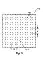
FIG. 3 shows a schematic view of a textured surface in an embodiment of surface textured roller, in accordance with the present invention; -
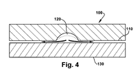
FIG. 4 shows a cross-sectional view of a textured roller surface configured for lubrication in an embodiment of surface textured roller, in accordance with the present invention; -
FIG. 5 shows a cross-sectional view of a textured roller surface configured for lubrication in another embodiment of surface textured roller, in accordance with the present invention; -
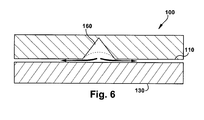
FIG. 6 shows a cross-sectional view of a textured roller surface configured for lubrication in another embodiment of surface textured roller, in accordance with the present invention; -
FIG. 7 shows a schematic view of a textured surface in an embodiment of surface textured roller, in accordance with the present invention; and -
FIG. 8 shows a perspective view of an embodiment of a surface textured rolling element bearing, in accordance with the present invention. - It has been discovered that an advantage that may be realized in the practice of some embodiments of the surface textured rollers and the surface textured rolling element bearings described herein is that drivetrain rollers having surface textures, such as micropores, maintain improved lubrication between the rollers, gears, and other drivetrain articles therein in contact with the surface textured bearings. Another advantage that may be realized in some embodiments of the surface textured rollers and the surface textured rolling element bearings described herein is that the surface textured rollers address problems associated with lubrication under extreme operating conditions due to the texturing itself. The textured surface enhances lubrication even in an operating regime where there is high stress causing elastic deformation of mating surfaces between the surfaced textured rollers and engine articles therein.
- Another advantage that may be realized in some embodiments of the surface textured rollers and the surface textured rolling element bearings described herein is that the surface textured rollers reduce frictional stress by improving the lubrication film integrity, life, and efficiency. Embodiments of the surface textured rollers improve lubrication depending on the availability of the lubricant and enhance performance of drivetrain articles with rolling and/or sliding contacts between them. For starved conditions where insufficient lubricant prevents formation of a film, the surface textures help pin lubricant droplets to the roller surface due to surface tension effect. These droplets in turn take up the frictional load and thus aid in the lubrication. The pinning down of droplets does not require very high speeds and the speed independent film forming capability is unlike conventional lubrication such as for example in journal bearings or ball bearings.
- For conditions where the lubricant supply is abundant but the combination of frictional load, drivetrain speed, and roller geometry is not enough to sustain a film, the surface textures act as reservoirs for the lubricant and help increase pressure in the film so that it can be sustained even under adverse conditions. The surface textures acting as reservoirs provide for an effective means for lubrication and is virtually equivalent to a transition from a boundary lubricated regime to an elastohydrodynamic or even hydrodynamic lubrication regime.
- It has also been discovered that another advantage that may be realized in some embodiments of the surface textured rollers and the surface textured rolling element bearings described herein is that the reduced frictional stress due to improved lubrication allows for the design of a more efficient turbine drivetrain, drivetrain articles therein, and/or other mechanical systems where bearings are used, such as a gearbox and a wind turbine as well as secondary systems such as lubrication pumps and cooling systems.
- Referring to
FIG. 1 , a schematic view of an embodiment of a rotatingelectric machine 10 is shown. In an embodiment, the rotatingelectric machine 10 may include a wind turbine drivetrain and hereon in will have thereference numeral 10 unless otherwise noted.Wind turbine drivetrain 10 may comprise agearbox 12 provided between arotor 14 and agenerator 16.Rotor 14 may have a plurality of blades (not shown). As wind blows,rotor 14 may be rotated due to the force of the wind. The speed of rotation ofrotor 14 may vary as a function of the wind speed. The rotation ofrotor 14 may be transmitted viagearbox 12 to the rotor ofgenerator 16.Rotor 14 may be designed to transfer wind energy into rotation efficiently. However, the rotor ofgenerator 16 may be designed to increase the speed of rotation produced byrotor 14 to the more desirable speed for driving the rotor ofgenerator 16. - In an embodiment,
gearbox 12 may comprise aplanetary gear set 18, an intermediate gear set 20, and a high-speed gear set 22 provided inside agearbox housing 24.Rotor 14 may be coupled via arotor shaft 26 toplanetary gear set 18.Planetary gear set 18 may comprise aplanetary gear 28, asun gear 30, and aring gear 32.Ring gear 32 may extend aroundsun gear 30 and may have teeth around its inner circumference. Sungear 30 may also have teeth around its outer circumference. The teeth ofplanetary gear 28 mesh with the teeth ofsun gear 30 andring gear 32. In addition,planetary gear 28 may be coupled torotor shaft 26. Asrotor 14 rotatesrotor shaft 26,planetary gear 28 may be driven aroundsun gear 30 causingsun gear 30 to rotate.Planetary gear set 18 may be supported by a plurality of surface texturedrolling element bearings - Sun
gear 30 may be coupled via afirst gear shaft 42 tointermediate gear set 20. In an embodiment,sun gear 30 may be smaller thanplanetary gear 28 and may rotate at a speed greater thanrotor shaft 26. Therefore,gear shaft 42 may also rotate at a speed greater thanrotor shaft 26.Intermediate gear set 20 may comprise a firstintermediate gear 44 and a secondintermediate gear 46 that may cooperate to increase the speed of rotation further. Secondintermediate gear 46 is coupled to asecond gear shaft 48 which may be coupled to high-speed gear set 22. In an embodiment, firstintermediate gear 44 may be larger than secondintermediate gear 46 so that secondintermediate gear 46 rotates at a speed greater thanfirst gear shaft 42.Intermediate gear set 20 may also be supported by a plurality of surfaced texturedrolling element bearings - High-
speed gear set 22 may comprise a first high-speed gear 58 and a second high-speed gear 60 that may cooperate to increase the speed of rotation still further. Second high-speed gear 50 may be coupled togenerator 16 via anoutput shaft 62. High-speed gear set 22 may be supported via corresponding surface textured rollingelement bearings speed gear 58 may be larger than second high-speed gear 60. Therefore, second high-speed gear 60 may rotate at a speed greater than first high-speed gear 58. Consequently,output shaft 62 may rotate at a speed greater thansecond gear shaft 48.Generator 16 may convert the rotational energy ofoutput shaft 62 into electricity. - Friction, wear, and lubrication are illustrative parameters to control for enhanced life and reliable operation of many mechanical components. For low speed and high load tribological applications with rolling and/or sliding contact, such as between rollers and engine articles therein, for example in a wind turbine gearbox, generating an appropriate film thickness for a lubricant is difficult and is thus a factor when designing the aforementioned components for longer life. In an illustrated embodiment, see
FIG. 1 , each surface textured rolling element bearing (34, 36, 38, 40, 50, 52, 54, 56, 64, 66, 68, and 70) includes one or more dimpled surfaces configured to hold lubricant for providing lubrication. - As described herein, "dimpled" may be referred to as a surface having a plurality of micropores or grooves formed in a predetermined pattern. The pattern may vary depending on the application of the roller. In an embodiment, the pores may be micro-sized pores configured to hold lubricant for enhanced lubrication. Surface texture in the form of pores on a roller surface is an effective means for lubrication under conditions of elastic deformation of contact surfaces. As a result, friction and wear are substantially reduced. Additional details pertaining to dimpled roller surfaces are explained in detail herein.
- In an embodiment, the surface textured rolling element bearings referred in
FIG. 1 may be surface textured rolling element bearings described herein or rolling element bearings that may be capable of having the surface textured with micropores, as described herein. In an embodiment, the rotatingelectric machine 10, and in particular, the wind turbine drivetrain described inFIG. 1 having the surface textured rolling element bearings is not meant to limit the application(s) of the surface textured rolling element bearings described herein. The surface textured rolling element bearings of embodiments of the present invention are not limited to any one particular machine and may be used in other applications where a high frictional load-low engine speed environment exists such as a drive train in a turbine; a cement, a sugar, and/or a paper mill; an off-highway vehicle; and a marine engine and/or drivetrain. - Referring to
FIG. 2 , an embodiment of a surface textured roller is shown. As discussed herein,roller 100 may have asurface 110 having a plurality ofmicropores 120 therein configured to hold lubricant for providing lubrication betweenroller 100 and an article in contact with it. In an embodiment,roller 100 may be configured to hold lubricant for providing lubrication betweenroller 100 and an article in contact with it under high frictional load and low speed conditions. In an embodiment,micropores 120 may have at least a geometry selected from at least one of the group consisting of a hemisphere, an ellipsoid, a cone, and a diamond shape (seeFIG. 4 ,FIG. 5 ,FIG. 6 , andFIG. 7 respectively), and combinations thereof. In another embodiment,micropores 120 may have hemisphere or diamond shaped geometry. - In an embodiment,
roller 100 may have dimensions of approximately 7 cm wide, approximately 34.3 cm bore, and approximately 45.7 cm outer diameter. The foregoing embodiment is not meant to limit the size of the surface textured roller. The size of the surface textured roller of various embodiments of the present invention is not limited to any one particular size and any size surface textured roller that may be used in applications where a high frictional load and low speed condition exists is encompassed by the present invention. - An advantage that may be realized in the practice of some embodiments of the surface textured roller is that the surface texturing in the form of
micropores 120 may enhance lubrication by providing improved availability of the lubricant. During operating conditions when the supply of lubricant is often limited,micropores 120 may hold the lubricant at the micropore regions on thesurface 110 due to a surface tension effect. Another advantage that may be realized in an embodiment, during operating conditions when the supply of lubricant is generally abundant, but a combination of load, speed, and geometry ofroller 100 is not sufficient to sustain a lubricant film betweenroller 100 and an article it may be in contact with,micropores 120 may act as reservoirs of lubricant. As a result, a lubricant film is sustained betweenroller 100 and the article it may be in contact with even under adverse operating conditions of the machine. - Even though the surface texture of an embodiment of the surface textured roller is explained in detail with reference to a
general roller 100, the surface texture is equally applicable to other surface textured rollers. In an embodiment, such rollers may be selected from the group consisting of a cylindrical roller, a spherical roller, and a taper roller. In another embodiment, the surface textured roller may be a cylindrical roller. - Referring to
FIG. 3 , a schematic view ofsurface 110 in an embodiment of surface textured roller is shown in accordance with the aspects ofFIG. 2 . As described herein,surface 110 ofroller 100 may include a plurality ofmicropores 120 thereon configured to hold lubricant for providing lubrication betweenroller 100 and an article it may be in contact with. The plurality ofmicropores 120 may be formed in a predetermined pattern. The pattern may be selected from the group consisting of random, semi-random and an array. - In one embodiment, the predetermined pattern may be an array, i.e., a grid-like pattern, with regular spacing "w" between
micropores 120. In an embodiment, the spacing between the plurality of micropores may be in a range from approximately 25 micrometers (µm) to approximately 150 µm. In another embodiment, the spacing between the plurality ofmicropores 120 may be in a range from approximately 80 µm to approximately 150 µm. In an embodiment ofmicropores 120, the diameter ofmicropores 120 may be in a range from approximately 25 µm to approximately 75 µm. In another embodiment, the diameters ofmicropores 120 may be in a range from approximately 50 µm to approximately 75 µm. In an embodiment ofmicropores 120, the depth ofmicropores 120 insurface 110 may be in range from 5 µm to approximately 10 µm. - In another embodiment, the predetermined pattern may be a grid-like pattern with irregular spacing "w" between
micropores 120. Similarly, any number of patterns may be envisaged. One having ordinary skill in the art will recognize that the pattern, diameter, depth, spacing betweenmicropores 120 may be varied depending on the application ofroller 100 without any undue experimentation because for example, for smaller size bearings, the area contributed from the textures or the density of the textures in the contact zone may be the same as that for larger size bearings. Correspondingly, the surface textures may be scaled up or down provided other parameters including but not limited to sliding velocity and pressure are approximately the same.Micropores 120 may be formed by manufacturing techniques including but not limited to laser machining, water jet machining, abrasive jet machining, electrochemical machining, electro discharge machining, or a combination thereof. The aforementioned techniques are known in the art and for the sake of clarity, no further discussion is provided. - Referring to
FIG. 4 ,FIG. 5 , andFIG. 6 , (described herein), a cross-sectional view of a textured surface of roller 100 (of which only a portion is illustrated) configured for lubrication in an embodiment of a surface textured roller bearing is shown. In an embodiment,roller 100 may comprise asurface 110 having a plurality ofmicropores 120. In an embodiment,micropores 120 have a hemisphere geometry. In other embodiments,micropores 120 may have at least a geometry selected from at least one of the group consisting of anellipsoid 150, acone 160, and a diamond shape 170 (seeFIG. 5 ,FIG. 6 , andFIG. 7 respectively), and combinations thereof.Roller 100 may be configured to mate/be in contact with anarticle 130 in applications such as wind turbines, gearboxes, etc that operate under high load and low speed conditions as well as racers of a surface textured rolling element described herein. As described herein,micropores - During adverse operating conditions, the volume of
micropores Micropores micropores roller 100 andarticle 130. As a result, a lubricant film is sustained betweenroller 100 andarticle 130 even under adverse conditions of the machine. - In an embodiment of
roller 100,surface 110 having a plurality ofmicropores 120 may lead to substantial reduction in friction over a wide range covering boundary to mixed lubrication conditions between contact surfaces ofroller 100 andarticle 130. Boundary lubrication occurs when a fluid fails to develop into a complete fluid film, i.e., hydrodynamic lubrication, allowing occasional contact between high points, known as asperities, of sliding wear surfaces. The mixed lubrication regime includes both elastohydrodynamic and boundary lubricated regimes. Plurality ofmicropores 120 reduce friction over boundary and mixed regimes, with normal lubricants, which do not have additives. Normal lubricants without additives typically may avoid tribochemical reactions leading to degradation of contact surfaces. - Referring to
FIG. 7 , a schematic view ofsurface 110 in an embodiment of surface textured roller is shown. As described herein,surface 110 of roller 100 (not shown in its entirety) may include a plurality of diamond shapedmicropores 170 thereof configured to hold lubricant for providing lubrication betweenroller 100 and an article it may be in contact there with. - Referring to
FIG. 8 , a perspective view of an embodiment of a surface textured rolling element bearing 200 is shown in accordance with the aspects ofFIG. 2 . The element bearing 200 comprises anouter race 210; aninner race 220; and a plurality ofrollers 100 betweenouter race 210 andinner race 220. Surface textured rolling element bearing 200 may additionally comprise a cage, not shown. A rolling element bearing, the components therein, and the interrelation between the foregoing are known to those having ordinary skill in the art, and thus, for the sake of clarity, no further discussion is provided regarding the same. - In an embodiment of surface textured rolling element bearing 200, each
roller 100 may comprise a plurality ofmicropores 120 in a surface thereof. The characteristics and various embodiments ofroller 100 are described herein and thus, for the sake of clarity, no further description is provided. In an embodiment,outer race 210 may comprise a plurality ofmicropores 120 in asurface 230 thereof. In an embodiment,inner race 220 may also comprise a plurality ofmicropores 120 in asurface 240 thereof. The characteristics and various embodiments of the plurality ofmicropores 120 are described herein, and equally apply when in use withouter race 210 andinner race 220, and thus, for the sake of clarity, no further description is provided. The same advantages that may be realized in the practice of some embodiments of the surfacetextured roller 100, and in particular, lubrication advantages offered bymicropores 120 thereof and described herein, may also be realized in the practice of some embodiments of the surface textured rollingelement bearings 200 described herein, in particular,micropores 120 in thesurface 230 ofouter race 210 and in thesurface 240 ofinner race 220 described herein and thus, for the sake of clarity, no further description is provided. - The terms "first," "second," and the like, herein do not denote any order, quantity, or importance, but rather are used to distinguish one element from another, and the terms "a" and "an" herein do not denote a limitation of quantity, but rather denote the presence of at least one of the referenced item. The modifier "approximately" used in connection with a quantity is inclusive of the stated value and has the meaning dictated by the context, (e.g., includes the degree of error associated with measurement of the particular quantity). The suffix "(s)" as used herein is intended to include both the singular and the plural of the term that it modifies, thereby including one or more of that term (e.g., the metal(s) includes one or more metals). Ranges disclosed herein are inclusive and independently combinable (e.g., ranges of "up to approximately 25 wt %, or, more specifically, approximately 5 wt % to approximately 20 wt %", is inclusive of the endpoints and all intermediate values of the ranges of "approximately 5 wt % to approximatley 25 wt %," etc).
- While various embodiments are described herein, it will be appreciated from the specification that various combinations of elements, variations or improvements therein may be made by those skilled in the art, and are within the scope of the invention. In addition, many modifications may be made to adapt a particular situation or material to the teachings of the invention without departing from essential scope thereof. Therefore, it is intended that the invention not be limited to the particular embodiment disclosed as the best mode contemplated for carrying out this invention, but that the invention will include all embodiments falling within the scope of the appended claims.
- Various aspects and embodiments of the present invention are defined by the following numbered clauses:
- 1. A surface textured roller comprising:
- a plurality of micropores in a surface thereof, the plurality of micropores having at least a geometry selected from at least one of the group consisting of a hemisphere, a diamond shape, an ellipsoid, and a cone, and combinations thereof.
- 2. A surface textured roller according to clause 1, wherein the plurality of micropores comprise the hemisphere or the diamond shape geometry.
- 3. A surface textured roller according to any preceding clause, wherein the plurality of micropores have a depth of approximately 5 micrometers (µm) to approximately 10 µm.
- 4. A surface textured roller according to any preceding clause, wherein the roller is selected from the group consisting of a cylindrical roller, a spherical roller, and a taper roller.
- 5. A surface textured roller according to any preceding clause, wherein the roller is a cylindrical roller.
- 6. A surface textured roller according to any preceding clause, wherein the plurality of micropores have a diameter of approximately 25 micrometers (µm) to approximately 75 µm.
- 7. A surface textured roller according to any preceding clause, wherein the spacing between the plurality of micropores is in a range from approximately 25 micrometers (µm) to approximately 150 µm.
- 8. A surface textured rolling element bearing comprising:
- an outer race;
- an inner race; and
- a plurality of rollers between the outer race and the inner race, the plurality of rollers having a plurality of micropores in a surface thereof, the plurality of micropores having at least a geometry selected from at least one of the group consisting of a hemisphere, a diamond shape, an ellipsoid, and a cone, and combinations thereof.
- 9. A surface textured rolling element bearing according to any preceding clause, wherein the plurality of micropores comprise the hemisphere or the diamond shape geometry.
- 10. A surface textured rolling element bearing according to any preceding clause, wherein the plurality of micropores have a depth of approximately 5 micrometers (µm) to approximately 10 µm.
- 11. A surface textured rolling element bearing according to any preceding clause, wherein the roller is selected from the group consisting of a cylindrical roller, a spherical roller, and a taper roller.
- 12. A surface textured rolling element bearing according to any preceding clause, wherein the roller is a cylindrical roller.
- 13. A surface textured rolling element bearing according to any preceding clause, wherein the plurality of micropores have a diameter of approximately 25 micrometers (µm) to approximately 75 µm.
- 14. A surface textured rolling element bearing according to any preceding clause, wherein the spacing between the plurality of micropores is in a range from approximately 25 micrometers (µm) to approximately 150 µm.
- 15. A surface textured rolling element bearing according to any preceding clause, wherein the inner race may comprise a plurality of micropores in a surface thereof, the plurality of micropores having at least a geometry selected from at least one of the group consisting of a hemisphere, a diamond shape, an ellipsoid, and a cone, and combinations thereof.
- 16. A surface textured rolling element bearing according to any preceding clause, wherein the outer race may comprise a plurality of micropores in a surface thereof, the plurality of micropores having at least a geometry selected from at least one of the group consisting of a hemisphere, a diamond shape, an ellipsoid, and a cone, and combinations thereof.
- 17. A surface textured rolling element bearing according to any preceding clause additionally comprising a cage.
- 18. A gearbox comprising:
- a gearbox including a gear set disposed within the gearbox, the gear set including at least two gears meshing with one another; and
- a surface textured roller element bearing supporting the gear set, the surface textured roller element bearing comprising:
- an outer race;
- an inner race; and
- a plurality of rollers between the outer race and the inner race, the plurality of rollers having a plurality of micropores in a surface thereof, the plurality of micropores having at least a geometry selected from at least one of the group consisting of a hemisphere, a diamond shape, an ellipsoid, and a cone, and combinations thereof.
- 19. A gearbox according to any preceding clause, wherein the plurality of micropores have a depth of approximately 5 micrometers (µm) to approximately 10 µm.
- 20. A wind turbine comprising:
- a rotor;
- a generator operable to generate power;
- a gearbox provided between the rotor and the generator, the gearbox including a gear set disposed within the gearbox, the gear set including at least two gears meshing with one another; and
- a surface textured rolling element bearing supporting the gear set, the surface textured rolling element bearing comprising:
- an outer race;
- an inner race; and
- a plurality of rollers between the outer race and inner race, the plurality of rollers having a plurality of micropores in a surface thereof, the plurality of micropores having at least a geometry selected from at least one of the group consisting of a hemisphere, a diamond shape, an ellipsoid, and a cone, and combinations thereof.
Claims (10)
- A surface textured roller (100) comprising:a plurality of micropores (120) in a surface (110) thereof, the plurality of micropores (120) having at least a geometry selected from at least one of the group consisting of a hemisphere, a diamond shape (170), an ellipsoid (150), and a cone (160), and combinations thereof.
- A surface textured roller (100) according to claim 1, wherein the plurality of micropores (120) comprise the hemisphere or the diamond shape (170) geometry.
- A surface textured roller (100) according to any preceding claim, wherein the plurality of micropores (120) have a depth of approximately 5 micrometer (µm) to approximately 10 µm.
- A surface textured roller (100) according to any preceding claim, wherein the roller (100) is selected from the group consisting of a cylindrical roller, a spherical roller, and a taper roller.
- A surface textured roller (100) according to any preceding claim, wherein the plurality of micropores (120) have a diameter of approximately 25 micrometers (µm) to approximately 75 µm.
- A surface textured rolling element bearing (200) comprising:an outer race (210);an inner race (220); anda plurality of rollers (100) between the outer race (210) and the inner race (220), the plurality of rollers (100) having a plurality of micropores (120) in a surface (230) thereof, the plurality of micropores (120) having at least a geometry selected from at least one of the group consisting of a hemisphere, a diamond shape (170), an ellipsoid (150), and a cone (160), and combinations thereof.
- A surface textured rolling element bearing (200) according to claim 6, wherein the plurality of micropores (120) comprise the hemisphere or the diamond shape (170) geometry.
- A surface textured rolling element bearing (200) according to claim 6 or claim 7, wherein the plurality of micropores (120) have a depth of approximately 5 micrometers (µm) to approximately 10 µm.
- A gearbox (12) comprising:a gearbox (12) including a gear set disposed within the gearbox (12), the gear set including at least two gears meshing with one another; anda surface textured roller element bearing (200) supporting the gear set, the surface textured roller element bearing (200) comprising:an outer race (210);an inner race (220); anda plurality of rollers (100) between the outer race (210) and the inner race (220), the plurality of rollers (100) having a plurality of micropores (120) in a surface (110) thereof, the plurality of micropores (120) having at least a geometry selected from at least one of the group consisting of a hemisphere, a diamond shape (170), an ellipsoid (150), and a cone (160), and combinations thereof.
- A wind turbine comprising:a rotor (14);a generator (16) operable to generate power;a gearbox (12) provided between the rotor (14) and the generator (16), the gearbox (12) including a gear set disposed within the gearbox (12), the gear set including at least two gears meshing with one another; anda surface textured rolling element bearing (200) supporting the gear set, the surface textured rolling element bearing (200) comprising:an outer race (210);an inner race (220); anda plurality of rollers (100) between the outer race (210) and inner race (220), the plurality of rollers (100) having a plurality of micropores (120) in a surface (110) thereof, the plurality of micropores (120) having at least a geometry selected from at least one of the group consisting of a hemisphere, a diamond shape (170), an ellipsoid (150), and a cone (160), and combinations thereof.
Applications Claiming Priority (1)
| Application Number | Priority Date | Filing Date | Title |
|---|---|---|---|
| US12/649,510 US8123413B2 (en) | 2009-12-30 | 2009-12-30 | Surface textured rollers |
Publications (2)
| Publication Number | Publication Date |
|---|---|
| EP2341248A2 true EP2341248A2 (en) | 2011-07-06 |
| EP2341248A3 EP2341248A3 (en) | 2014-01-01 |
Family
ID=43608874
Family Applications (1)
| Application Number | Title | Priority Date | Filing Date |
|---|---|---|---|
| EP10194839.6A Withdrawn EP2341248A3 (en) | 2009-12-30 | 2010-12-14 | Surface textured rollers |
Country Status (3)
| Country | Link |
|---|---|
| US (1) | US8123413B2 (en) |
| EP (1) | EP2341248A3 (en) |
| CN (1) | CN102116348B (en) |
Cited By (1)
| Publication number | Priority date | Publication date | Assignee | Title |
|---|---|---|---|---|
| EP3798456A1 (en) * | 2019-09-27 | 2021-03-31 | Flender GmbH | Slide bearing |
Families Citing this family (26)
| Publication number | Priority date | Publication date | Assignee | Title |
|---|---|---|---|---|
| US20130170780A1 (en) * | 2010-02-23 | 2013-07-04 | Nsk Ltd. | Roller Bearing and Method for Manufacturing the Same |
| KR101843196B1 (en) * | 2010-11-18 | 2018-03-29 | 두산인프라코어 주식회사 | Rocker arm shaft having improved abrasion resistance and of rocker arm shaft-bush assembly comprising the rocker arm shaft |
| CN102954190B (en) * | 2011-08-19 | 2015-09-09 | 鸿富锦精密工业(深圳)有限公司 | Speed reducer |
| US9261139B2 (en) | 2013-02-06 | 2016-02-16 | Trelleborg Sealing Solutions Us | Friction-reducing geometric surface feature |
| KR20150055367A (en) * | 2013-11-13 | 2015-05-21 | 현대중공업 주식회사 | Rocker Arm Shaft for Ship Engine |
| WO2015175603A1 (en) | 2014-05-15 | 2015-11-19 | The Timken Company | Bearing and method of forming a bearing |
| US9956985B2 (en) * | 2016-02-16 | 2018-05-01 | Steering Solutions Ip Holding Corporation | Steering shaft assembly |
| US20170356497A1 (en) * | 2016-06-13 | 2017-12-14 | Caterpillar Inc. | Bearing race |
| US10100875B2 (en) | 2016-07-26 | 2018-10-16 | General Electric Company | Roller bearing and systems including such |
| US10030708B2 (en) | 2016-07-29 | 2018-07-24 | General Electric Company | Roller bearing cage for use in a gearbox |
| US10138940B2 (en) | 2016-08-09 | 2018-11-27 | General Electric Company | Roller bearing cage for use in a gearbox |
| US10400678B2 (en) | 2017-01-03 | 2019-09-03 | General Electric Company | Apparatus and system for light-weight, flexible double-helical gear |
| US10508731B2 (en) | 2017-01-05 | 2019-12-17 | General Electric Company | Apparatus and method for managing pinch loads on a gear |
| US10247298B2 (en) | 2017-01-10 | 2019-04-02 | General Electric Company | Resilient bearing pin and gear assemblies including resilient bearing pins |
| US10228024B2 (en) | 2017-01-10 | 2019-03-12 | General Electric Company | Reduced-weight bearing pins and methods of manufacturing such bearing pins |
| US10247297B2 (en) | 2017-01-18 | 2019-04-02 | General Electric Company | Apparatus for a gearbox with multiple scavenge ports |
| US10408304B2 (en) | 2017-02-07 | 2019-09-10 | General Electric Company | Gears having reduced roller element stresses and methods of manufacturing such gears |
| US10882070B2 (en) | 2017-03-28 | 2021-01-05 | Steering Solutions Ip Holding Corporation | Method of manufacturing a steering shaft assembly |
| US10451113B2 (en) | 2017-05-18 | 2019-10-22 | General Electric Company | Bearing cages for roller bearing assemblies |
| US10260563B2 (en) | 2017-05-18 | 2019-04-16 | General Electric Company | Bearing cages for roller bearing assemblies |
| US10619721B2 (en) * | 2017-07-21 | 2020-04-14 | General Electric Company | Drivetrain assembly for a wind turbine |
| US10385961B2 (en) | 2017-10-25 | 2019-08-20 | General Electric Company | Planetary gear system |
| CN109488694B (en) * | 2018-12-26 | 2020-03-31 | 西安交通大学 | Surface texture assisted rolling bearing lubricating method |
| JP7598701B2 (en) * | 2019-04-26 | 2024-12-12 | 株式会社ジェイテクト | Rolling bearings |
| EP3904715A1 (en) | 2020-04-27 | 2021-11-03 | Delavan, Inc. | Bearing system |
| ES1281562Y (en) * | 2021-07-29 | 2022-02-04 | Fersa Innova S L U | TEXTURED ROLLER BEARING |
Family Cites Families (27)
| Publication number | Priority date | Publication date | Assignee | Title |
|---|---|---|---|---|
| US4323401A (en) * | 1975-11-17 | 1982-04-06 | Caterpillar Tractor Co. | Bearing having an array of microasperities |
| US4619534A (en) * | 1984-09-12 | 1986-10-28 | Reed Tool Company | Roller cutter drill bit having a texturized seal member |
| JPH01224519A (en) | 1988-03-01 | 1989-09-07 | Yoshiteru Ebara | Pressure dimple |
| US5120395A (en) * | 1990-11-13 | 1992-06-09 | General Electric Company | Method for making a gas turbine engine component with a textured surface |
| JPH04321816A (en) * | 1991-04-18 | 1992-11-11 | Ntn Corp | Gear box bearing of helicopter |
| US5120325A (en) * | 1991-06-12 | 1992-06-09 | Fleshtones Products Co., Inc. | Color-matched sterile adhesive bandages containing melanin-like pigment composition |
| DE59201549D1 (en) * | 1992-04-11 | 1995-04-06 | Gehring Gmbh & Co Maschf | Process for finishing workpiece surfaces. |
| DE4316012C2 (en) * | 1993-05-13 | 1998-09-24 | Gehring Gmbh & Co Maschf | Process for finishing workpiece surfaces |
| US5498096A (en) * | 1994-10-28 | 1996-03-12 | Hoover Universal, Inc. | Tube joint formed with adhesive and metal forming process |
| US5683183A (en) * | 1995-09-26 | 1997-11-04 | Nsk Ltd. | Spindle device and bearing device therefor |
| US5967672A (en) * | 1996-02-28 | 1999-10-19 | Ntn Corporation | Machine parts making rolling or sliding surfaces formed with discontinuous grooves |
| NL1003141C2 (en) * | 1996-05-15 | 1997-11-18 | Skf Ind Trading & Dev | Rolling bearing with improved wear characteristics, and rolling element for such a bearing. |
| US5834094A (en) * | 1996-09-30 | 1998-11-10 | Surface Technologies Ltd. | Bearing having micropores and design method thereof |
| NL1006971C2 (en) * | 1997-09-08 | 1999-03-09 | Skf Ind Trading & Dev | Rolling bearing with improved rolling surfaces. |
| JP2000205267A (en) | 1998-11-11 | 2000-07-25 | Nsk Ltd | Rolling bearings for information office equipment |
| JP4261730B2 (en) * | 1999-04-22 | 2009-04-30 | キヤノン株式会社 | Hydrodynamic bearing structure and deflection scanning device |
| US6739238B2 (en) * | 2000-11-20 | 2004-05-25 | Nissan Motor Co., Ltd. | Sliding structure for a reciprocating internal combustion engine and a reciprocating internal combustion engine using the sliding structure |
| US6655845B1 (en) * | 2001-04-22 | 2003-12-02 | Diamicron, Inc. | Bearings, races and components thereof having diamond and other superhard surfaces |
| JP2004316699A (en) * | 2003-04-11 | 2004-11-11 | Nsk Ltd | Linear motion guide bearing device |
| JP4754234B2 (en) * | 2005-02-17 | 2011-08-24 | Ntn株式会社 | Rolling bearing |
| JP2006320907A (en) * | 2005-05-17 | 2006-11-30 | Muneharu Kutsuna | Micro laser peening treatment and parts using micro laser peening treatment using powder and coating |
| JP2008095903A (en) | 2006-10-13 | 2008-04-24 | Ihi Corp | Plain bearing with texture and method for estimating performance thereof |
| GB2442969A (en) * | 2006-10-19 | 2008-04-23 | Ford Global Tech Llc | Friction bearing |
| JP2008298144A (en) * | 2007-05-30 | 2008-12-11 | Ntn Corp | Method of processing of rolling contact surface |
| WO2008069133A1 (en) * | 2006-12-04 | 2008-06-12 | Ntn Corporation | Rolling member and method of processing of rolling contact surface |
| US7914250B2 (en) * | 2006-12-08 | 2011-03-29 | General Electric Company | Method and system for estimating life of a gearbox |
| US20090139799A1 (en) * | 2007-11-30 | 2009-06-04 | General Electric Company | Textured surfaces for gears |
-
2009
- 2009-12-30 US US12/649,510 patent/US8123413B2/en not_active Expired - Fee Related
-
2010
- 2010-12-14 EP EP10194839.6A patent/EP2341248A3/en not_active Withdrawn
- 2010-12-30 CN CN201010624659.6A patent/CN102116348B/en not_active Expired - Fee Related
Non-Patent Citations (1)
| Title |
|---|
| None |
Cited By (2)
| Publication number | Priority date | Publication date | Assignee | Title |
|---|---|---|---|---|
| EP3798456A1 (en) * | 2019-09-27 | 2021-03-31 | Flender GmbH | Slide bearing |
| WO2021058262A1 (en) | 2019-09-27 | 2021-04-01 | Flender Gmbh | Plain shaft bearing |
Also Published As
| Publication number | Publication date |
|---|---|
| US8123413B2 (en) | 2012-02-28 |
| CN102116348B (en) | 2016-01-13 |
| CN102116348A (en) | 2011-07-06 |
| EP2341248A3 (en) | 2014-01-01 |
| US20110156399A1 (en) | 2011-06-30 |
Similar Documents
| Publication | Publication Date | Title |
|---|---|---|
| US8123413B2 (en) | Surface textured rollers | |
| US20090139799A1 (en) | Textured surfaces for gears | |
| JP5031091B2 (en) | Speed increaser for wind power generator and wind power generator | |
| CN102472253B (en) | Wind Turbine Main Bearings | |
| JP5345048B2 (en) | Wind power transmission and wind power generator | |
| JP6267826B2 (en) | HYBRID BEARING, WIND GENERATOR WITH HYBRID BEARING, USING HYBRID BEARING, AND HYBRID BEARING OPERATION METHOD | |
| JP5622716B2 (en) | Planetary gear device and wind power generator | |
| JP6018203B2 (en) | Journal bearing for use in orbiting circular transmission and method for promoting hydrodynamic oil flow in journal bearing | |
| CN101603567B (en) | Sliding bearing of floating sleeve with forced floating function | |
| US20120051915A1 (en) | Planetary gear train with improved bearing structure and manufacture method of the same | |
| JP2011085218A (en) | Planetary bearing structure | |
| WO2013034389A2 (en) | Direct-drive wind turbine | |
| AU2010206051B2 (en) | Parallel gear unit for a gearbox for a wind turbine | |
| WO2011099148A1 (en) | Step-up gear device for wind-driven electricity generation device, and wind-driven electricity generation device | |
| JP2005036880A (en) | Planetary gear device and its rolling bearing | |
| US20190032708A1 (en) | Bearing arrangement for supporting a shaft of a gearbox | |
| CN114658831A (en) | Planetary gear box and wind power equipment | |
| Terrell et al. | Tribological challenges to the system | |
| Hansen et al. | Analysis of bearing steel exposed to rolling contact fatigue | |
| Kurashita | Rolling bearings for wind turbine generator | |
| WO2023212862A1 (en) | Planetary gearbox and wind power device | |
| CN102011797A (en) | Micro flexible combined rolling bearing | |
| Hao et al. | Design and performance analysis of herringbone groove journal bearings for high-speed gear pump | |
| WO2024016324A1 (en) | Planetary gearbox and wind power apparatus |
Legal Events
| Date | Code | Title | Description |
|---|---|---|---|
| PUAI | Public reference made under article 153(3) epc to a published international application that has entered the european phase |
Free format text: ORIGINAL CODE: 0009012 |
|
| AK | Designated contracting states |
Kind code of ref document: A2 Designated state(s): AL AT BE BG CH CY CZ DE DK EE ES FI FR GB GR HR HU IE IS IT LI LT LU LV MC MK MT NL NO PL PT RO RS SE SI SK SM TR |
|
| AX | Request for extension of the european patent |
Extension state: BA ME |
|
| PUAL | Search report despatched |
Free format text: ORIGINAL CODE: 0009013 |
|
| AK | Designated contracting states |
Kind code of ref document: A3 Designated state(s): AL AT BE BG CH CY CZ DE DK EE ES FI FR GB GR HR HU IE IS IT LI LT LU LV MC MK MT NL NO PL PT RO RS SE SI SK SM TR |
|
| AX | Request for extension of the european patent |
Extension state: BA ME |
|
| RIC1 | Information provided on ipc code assigned before grant |
Ipc: F03D 11/00 20060101AFI20131127BHEP |
|
| 17P | Request for examination filed |
Effective date: 20140701 |
|
| RBV | Designated contracting states (corrected) |
Designated state(s): AL AT BE BG CH CY CZ DE DK EE ES FI FR GB GR HR HU IE IS IT LI LT LU LV MC MK MT NL NO PL PT RO RS SE SI SK SM TR |
|
| 17Q | First examination report despatched |
Effective date: 20161216 |
|
| RIC1 | Information provided on ipc code assigned before grant |
Ipc: F03D 80/70 20160101AFI20180612BHEP |
|
| GRAP | Despatch of communication of intention to grant a patent |
Free format text: ORIGINAL CODE: EPIDOSNIGR1 |
|
| INTG | Intention to grant announced |
Effective date: 20180720 |
|
| STAA | Information on the status of an ep patent application or granted ep patent |
Free format text: STATUS: THE APPLICATION IS DEEMED TO BE WITHDRAWN |
|
| 18D | Application deemed to be withdrawn |
Effective date: 20181201 |