EP2341171A1 - Knitting yarn gripping device of flatbed knitting machine, and control method of the same - Google Patents
Knitting yarn gripping device of flatbed knitting machine, and control method of the same Download PDFInfo
- Publication number
- EP2341171A1 EP2341171A1 EP10016141A EP10016141A EP2341171A1 EP 2341171 A1 EP2341171 A1 EP 2341171A1 EP 10016141 A EP10016141 A EP 10016141A EP 10016141 A EP10016141 A EP 10016141A EP 2341171 A1 EP2341171 A1 EP 2341171A1
- Authority
- EP
- European Patent Office
- Prior art keywords
- gripping
- lock
- mounting plate
- moved
- knitting yarn
- Prior art date
- Legal status (The legal status is an assumption and is not a legal conclusion. Google has not performed a legal analysis and makes no representation as to the accuracy of the status listed.)
- Granted
Links
Images




Classifications
-
- D—TEXTILES; PAPER
- D04—BRAIDING; LACE-MAKING; KNITTING; TRIMMINGS; NON-WOVEN FABRICS
- D04B—KNITTING
- D04B7/00—Flat-bed knitting machines with independently-movable needles
- D04B7/30—Flat-bed knitting machines with independently-movable needles specially adapted for knitting goods of particular configuration
- D04B7/32—Flat-bed knitting machines with independently-movable needles specially adapted for knitting goods of particular configuration tubular goods
-
- D—TEXTILES; PAPER
- D04—BRAIDING; LACE-MAKING; KNITTING; TRIMMINGS; NON-WOVEN FABRICS
- D04B—KNITTING
- D04B15/00—Details of, or auxiliary devices incorporated in, weft knitting machines, restricted to machines of this kind
- D04B15/38—Devices for supplying, feeding, or guiding threads to needles
- D04B15/54—Thread guides
- D04B15/56—Thread guides for flat-bed knitting machines
- D04B15/565—Associated thread-clamping or thread-severing devices
Definitions
- the present invention relates to a knitting yarn gripping device of a flatbed knitting machine, arranged at a lateral side of a needle bed, for gripping a knitting yarn, and a control method of the same.
- a flatbed knitting machine 1 as is simplistically shown in Fig. 9 has at least one pair of needle beds 2 which are arranged in front and back to face each other so as to define a needle bed gap 3 therebetween. Front end portions of the knitting needles, not illustrated, are advanced from the front and back needle beds 2 into the needle bed gap 3 and are retracted therefrom so that a knitted fabric 4 such as e.g. a sweater can be shaped into a final form while being knitted continuously.
- a knitting yarn 6 is fed to the knitting needle on the needle beds 2 from a yarn feeder 5 moved over the needle bed gap 3.
- the yarn feeder 5 is moved to a location on a lateral side of the needle bed 2.
- the knitting yarn 6 extending from a final knitted loop in the knitted fabric 4 to the yarn feeder 5 is put in a slanted condition.
- the cutting of the knitting yarn 6 can allow smooth discharge of the knitted fabric 4 and can eliminate the need for splitting the knitting yarn 6 between the knitted fabrics 4 after discharged. Only the cutting results in floatation of a tip of the knitted yarn remaining on the yarn feeder 5 side, however.
- Gripping devices 8a, 8b are provided at an area on a lateral side of the needle bed gap 3 into and from which the knitting needles are advanced from the front and back needle beds 2 and retracted, so that when the knitting yarn 6 extending to the yarn feeder 5 is cut by the cutting device 7, the open/close gripping portions 9a, 9b catch and hold an end of the knitting yarn 6 while gripping it (See Patent Literature 1, for example).
- the gripping portions 9a, 9b are moved down to a lower limit of the stroke by the gripping devices 8a, 8b.
- the gripping portions 9a, 9b can be opened in the middle of the upward movement.
- the gripping portions 9a, 9b opened catch the knitting yarns 6a, 6b in the course of moving up to the upper point of the stroke.
- the gripping portions 9a, 9b are closed at the upper point of the stroke, to grip the knitting yarns 6a, 6b. After closed, the gripping portions 9a, 9b are moved downwards keeping the gripping of the knitting yarns 6a, 6b.
- the yarn feeders 5a, 5b are moved over the needle bed gap 3 so that the knitting yarns 6a, 6b gripped at their ends by the gripping portions 9a, 9b can be fed to the knitting needles advanced into and retracted from the needle bed gap 3.
- the gripping portions 9a, 9b can be opened to release the grip of the ends of the knitting yarns 6a, 6b.
- the knitting yarns 6a, 6b are gripped by the gripping devices 8a, 8b not only when they are put in a standby condition until the next knitting but also when they are moved downward temporarily.
- the knitted fabric 4 such as a sweater
- its body 4a and sleeve 4b are knitted in a tubular form in a body knitting area 2a and in a sleeve knitting area 2b at a lateral side of the body knitting area 2a, respectively.
- the sleeve 4b is knitted after the yarn feeder 5b for the knitting yarn 6 used for knitting the body 4a is temporarily moved outward of the needle bed 2, as represented in a full line, the knitting yarn 6 may possibly be knitted in together.
- Patent Literature 1 Japanese Examined Patent Publication No. Hei 4-74463
- the knitting yarn 6a may then be grazed and worn in the middle of being lifted up, to cause a yarn break, depending on material used for the knitting yarn 6a. Even if that does not cause the yarn break, as a result of the knitting yarn 6a being pulled overly, a tensile force may be increased overly so that the knitting yarn 6a may be dropped off from the gripping portion 9a.
- the present invention provides a knitting yarn gripping device of a flatbed knitting machine provided with a plurality of gripping mechanisms, which are each provided, at an upper end thereof, with a gripping portion for gripping a knitting yarn extending from a yarn feeder and are arranged in order between a movement zone where the yarn feeder is moved laterally of a needle bed and the needle bed, with a needle bed side as an inner side and a movement zone side as an outer side, each gripping mechanism comprising:
- the present invention is characterized in that the gripping mechanism further comprises a grip lock mechanism which is disposed at an upper portion of the mounting plate and is so structured that when the lock by the open/close lock mechanism is released and then the gripping portion is closed, the gripping portion is locked in a partly closed state so that it can be kept at a stage before gripping the knitting yarn, and then the lock of the gripping portion is released in the middle of the mounting plate being moved down to the standby position, whereby the gripping portion is closed to grip the knitting yarn.
- a grip lock mechanism which is disposed at an upper portion of the mounting plate and is so structured that when the lock by the open/close lock mechanism is released and then the gripping portion is closed, the gripping portion is locked in a partly closed state so that it can be kept at a stage before gripping the knitting yarn, and then the lock of the gripping portion is released in the middle of the mounting plate being moved down to the standby position, whereby the gripping portion is closed to grip the knitting yarn.
- the present invention provides a control method of a knitting yarn gripping device of a flatbed knitting machine provided with a plurality of gripping mechanisms, which are each provided, at an upper end thereof, with a gripping portion for gripping a knitting yarn extending from a yarn feeder and are arranged in order between a movement zone where the yarn feeder is moved laterally of a needle bed and the needle bed, with a needle bed side as an inner side and a movement zone side as an outer side,
- the prevent invention is characterized in that a distance for the inner gripping mechanism to move up from the standby position is set to be lower in level by only a predetermined difference than a distance for the outer gripping mechanism to move up, following the opening-and-closing and gripping procedures, so as to open the gripping portion.
- the mounting plate is driven to move up and down between an upper limit and a lower limit of a predetermined stroke and the gripping portion is opened and closed according to a distance for the operation plate to be moved down relative to the mounting plate.
- the mounting plate has, at an upper end portion thereof, the gripping portion mounted in an openable and closable manner.
- the operation plate actuated to open and close the gripping portion is disposed in an overlying relation with the mounting plate.
- the mounting plate and the operation plate are pulled each other by the tension spring and can be locked by the open/close lock mechanism to keep the gripping portion in the opened state.
- the gripping portion When the gripping portion is opened, it is required that the mounting plate is moved down to the lower limit range and the operation plate is locked by the operation lock mechanism, first, and then, the mounting plate is moved up. When the mounting plate is moved up to the upper limit range, the lock of the open/close lock mechanism is released so that the gripping portion can be closed to catch or grip the knitting yarn. Then, the mounting plate is moved down to the predetermined standby position which is above the lower limit area. Following these opening-and-closing and gripping procedures, the gripping portion can be moved up and down and opened and closed, to catch or grip the knitting yarn.
- the control means controls the mounting plates in such a manner that when the mounting plate is moved up and down by the outer gripping mechanism, following the opening-and-closing and gripping procedures, whereby the knitting yarn is caught or gripped by the gripping portion, the mounting plate of the inner gripping mechanism can be simultaneously moved up together from the standby position and then be moved down. Even when the inner gripping mechanism is moved up from the standby position, the gripping portion is not opened. This can avoid a possible problem that the gripping portion may be moved up in the state of gripping the knitting yarn to cause an overly increased tension of the knitting yarn that may cause a yarn break or a yarn cast-off.
- the gripping portion can be locked, when being in the middle of being closed, by the grip lock mechanism, to prevent the knitting yarn caught from being gripped.
- the knitting yarn can be supplied additionally from the yarn feeder to avoid an overly increased tension of the knitting yarn that may cause a close stitch or a yarn break on the knitted fabric side.
- the lock releasing portion can be moved down through the guide groove to allow the mounting plate to move down further. Since a stroke for allowing the mounting plate to move down can be added after the lock by the grip lock mechanism is released, the gripping portion even when moved up can be prevented from being opened during the downward movement to the standby position during which the operation plate is not locked by the operation lock mechanism.
- the gripping portion is put in the state in which it can be opened when moved up following the opening-and-closing and gripping procedures.
- the inner gripping mechanism when the outer gripping mechanism is moved up to catch the knitting yarn in the condition in which the knitting yarn extending from the yarn feeder to move in a lateral side of the needle bed is gripped by the inner gripping mechanism, the inner gripping mechanism is also moved up together. This can prevent exertion of an excess tension on the knitting yarn gripped by the inner gripping mechanism, to prevent a yarn break or a yarn cast-off. Since the grip by the inner gripping mechanism is performed at the predetermined standby position which is above the lower limit range, the inner gripping mechanism may be moved up therefrom to keep the grip or may alternatively be moved down therefrom first and then moved up, following the opening-and-closing and gripping procedures, to open the gripping portion. Thus, these two different modes can be selectively used, according to need.
- a distance for the inner gripping mechanism to move up from the standby position is set to be lower in level by only a predetermined difference than a distance for the outer gripping mechanism to move up, following the opening-and-closing and gripping procedures, so as to open the gripping portion.
- this level difference is predetermined in such a manner that the catching and gripping motion of the outer gripping portion opened is not hindered by an upper end of the inner gripping portion closed, the knitting yarn can be reliably caught and gripped by the outer gripping portion.
- Figs. 1-8 corresponding parts to the parts described in Fig. 9 are labeled the same reference characters, for avoidance of redundancy of explanation.
- Figs. 1-8 explanation on like-numbered parts corresponding to the parts previously explained may be omitted, for avoidance of redundancy of explanation.
- Alphabets A, B, C, and D added to the reference numerals throughout the drawing figures 2-8 indicate a front construction, a part of a rear construction, a left-side construction, and a plan construction, respectively. It is to be noted that the front direction corresponds to a lateral direction with respect to the flatbed knitting machine.
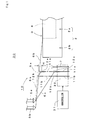
- Fig. 1 diagrammatically shows a part of the front view of a schematic construction of a knitting yarn gripping device 10 of a certain embodiment of the present invention as a part of a front view of a flatbed knitting machine 30.
- the knitting yarn gripping device 10 is provided, at one lateral side of a needle bed 2, with two gripping mechanisms 11a, 11b having basically the same construction as the gripping device 8 of Fig. 9 and a cutting device 7.
- the knitting yarn gripping device 10 may be provided with the same construction at the other lateral side of the needle bed 2 as well.
- the gripping mechanisms 11a, 11b have, at upper ends thereof, gripping portions 12a, 12b, and are driven to move up and down via a drive unit 32 which is controlled by a controller 31 which is control means for controlling the flatbed knitting machine 30.
- the controller 31 controls at least the inner gripping mechanism 11a so that the standby position where the gripping portion 12a is closed to grip an end of a knitting yarn 6a and stands in readiness can be set higher than a lower limit of a lifting-and-lowering stroke of the gripping mechanism 11a.
- a height of the standby position is set to be within such a range that a carriage can move in reciprocation along the needle bed without being interrupted.
- the standby position is set so that such a pressing mechanism can also move without being interrupted.
- the gripping mechanism 11a opens its gripping portion 12a when moving first downward to a lower limit than the standby position and then turns around to move upward.
- the gripping portion 12a is kept in the closed state.
- the gripping mechanism 11a can also be moved up while gripping the knitting yarn 6a by its gripping portion 12a.
- the inner gripping portion 12a is also moved up.
- the inner gripping portion 12a is moved up to a position equal in level to the outer gripping portion 12b, since the inner gripping portion 12a is closed, the inner gripping portion 12a lifts the knitting yarn 6b at its upper end. As a result of this, it becomes hard for the outer griping portion 12b to catch the knitting yarn 6b. Also, the knitting yarn 6a gripped by the inner gripping portion 12a is gripped by the outer gripping portion 12b as well.
- an upper position to which the inner gripping portion 12a is moved up is set to be lower by only a height difference H than an upper position to which the outer gripping portion 12b is moved up, in order not interrupt the gripping motion of the outer gripping portion 12b to open at an outer side so as to catch and grip the knitting yarn 6b.
- the height difference H is set to the order of e.g. 10mm.
- the height difference H produces the result that when both gripping portions 12a, 12b gripping the knitting yarn 6a are lowered to the standby positions equal in level to each other, the knitting yarn 6a extending between the gripping portions 12a, 12b is put in a slacked state.
- This slackness can prevent exertion of an excessive tensile force on the knitting yarn 6a even when only one of the gripping portions 12a, 12b is lowered to a position lower than the standby position and then returned around to move up to release the knitting yarn 6a.
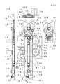
- Fig. 2 shows the state in which the gripping mechanism 11 is moved down to a lower limit of the stroke and the gripping portion 12 is closed.
- the gripping portion 12 is provided with three nip pawls 13, 14, 15, and the two outside nip pawls 13, 15 are associated, so that a front end portion of the gripping portion 12 is opened and closed in their cooperation with the inside nip pawl 14.
- the three nip pawls 13, 15; 14 are pivoted about a common nip pivot 17a to open and close the front end portion of the gripping portion.
- Two rods 16 are connected at their lower end portions to each other through an operation pivot 17b.
- the nip pawls 13, 15 and an upper end portion of the rod 16 are connected through a rod pivot 17c.
- the nip pawl 14 and the upper end portion of the rod 16 are connected through a rod pivot 17d.
- the nip pawls 13, 15 and 14, and the rods 16 form a linkage mechanism to allow the degree of opening and closing of the front end portions of the gripping portion to vary according to a distance between the nip pivot 17a and the operation pivot 17b.
- the nip pivot 17a is fixed to the mounting plate 18 at a location near an upper end thereof.
- the mounting plate 18 is nearly in the form of a vertically extending plate and has a slot 18a formed in an intermediate part thereof.
- the mounting plate 18 has a rack 18b formed at one lateral side thereof and has a cam recess 18c formed at the other lateral side thereof.
- a hook 20 of the open/close lock mechanism 19 is mounted on the mounting plate 18 at a location near a lower end portion thereof.
- the hook 20 has a nearly L-shaped form and is pivotally supported by a hook pivot 20a at a front end thereof on the long side. The long side of the hook 20 is pushed from the lateral side by a push spring 21 and is urged in a direction of a front end 20b of the hook on the short side.
- the operation pivot 17b is fixed to the operation plate 22 at a location near the upper end of the same.
- the operation plate 22 is connected to the mounting plate 18 through a tension spring 23.
- the tension spring 23 is accommodated in a space formed by a slot 22a formed in an intermediate portion of the operation plate 22 and the slot 18a of the mounting plate 18.
- the operation plate 22 is so disposed as to lay over the mounting plate 18 and has a notch 22b formed at a lateral side thereof on the side on which the cam recess 18c of the mounting plate 18 is formed.
- the cam recess 18c and the notch 22b are provided in order that a pivot pawl 26 pivotable about a pivot 25 can be operated by an operation lock mechanism 24.
- the rack 18b of the mounting plate 18 formed at the lateral side is meshed with a pinion 28.
- the mounting board 18 and the pinion 28 are main components of a drive unit 32 of Fig. 1 .
- a rotation shaft 29 of the pinion 28 is rotationally driven by a motor, the mounting plate 18 can be shifted in vertical position.
- the gripping mechanism 11 moves up and down in response to the movement of the mounting plate 18. Since the tension spring 23 urges the operation plate 22 in a direction in which it is moved closer to the mounting plate 18, the gripping portion 12 is urged in a direction in which it is closed via the linkage mechanism.
- the mounting plate 18 and the operation plate 22 are shifted in vertical position in such a manner as to slide over a support block 40.
- the support block 40 is mounted on a frame at a lateral side of the needle bed of the flatbed knitting machine.
- the support block 40 supports thereon the pivot 25 of the pivot pawl 26 and the rotation shaft 29.
- the support block 40 is provided, at a lower portion thereof, with an abutment portion 40a.
- the knitting yarn gripping device 10 includes a grip lock mechanism 50 for locking the linkage mechanism in the middle of the gripping portion 12 being closed, to only keep the gripping portion 12 in the stage of catching the knitting yarn prior to gripping it.
- the grip lock mechanism 50 includes a lock lever 51 and a wire spring 52.
- the lock lever 51 is urged by the wire spring 52 in the counterclockwise direction, when viewed from the front configuration 10A.
- the lock lever 51 is pivotally supported by the rod pivot 17b by which the nip pawl 14 and the upper end of the rod 16 are connected.
- the support block 40 is provided, at its upper portion, with a slanted surface 40b.
- the abutment portion 40a and the slanted surface 40b are respectively provided at a lower portion of a guide groove 40c and at an upper portion of the guide groove 40c in which the mounting plate 18 and the operation plate 22 are accommodated in the overlying relation with each other.
- Fig. 3 shows the state in which the mounting plate 18 is moved upward from the state of Fig. 2 , so that the gripping portion 12 is opened and locked by the open/close lock mechanism 19.
- the operation plate 22 urged by means of the tension spring 23 is moved up together.
- the pivot pawl 26 is urged by means of a leaf spring, not illustrated, so that its pawl portion 26a can be pressed against the lateral side of the operation plate 22.
- the roller 27 provided on the pivot pawl 26 is fitted in the cam recess 18c of the operation plate 18 so that the pawl portion 26a of the pivot pawl 26 can be fitted into the notch 22b.
- the support block 40 has, on the back side, substantially the same guide groove as the guide groove 40c. Like gripping mechanism 11 is accommodated in that guide groove on the back side, for upward and downward drive. In this regard, however, to allow the drive on the back side, a pinion 58 and a rotation shaft 59 are disposed at locations different from the locations where the pinion 28 and the rotation shaft 59 are disposed. Thus, the knitting yarn gripping portion 10 of Fig. 1 is provided with two gripping mechanisms 11a, 11b for a single support block 40.
- Fig. 4 shows the state in which the lock of the open/close lock mechanism 19 is released and also the gripping portion 12 is locked by a grip lock mechanism 50 in the middle of being closed.
- Fig. 3 when the mounting plate 18 and the operation plate 22 are interlocked by the open/close lock mechanism 19 and then the mounting plate 18 is moved upward, the front end 20b of the hook 20 abuts with the abutment portion 40a at the lower portion of the support block 40. As a result of this, the hook 20 is pivoted in the clockwise direction to disengage the intermediate portion 20c from the abutment portion 22c of the operation plate 22, so that the lock is released.
- the operation plate 22 Since the operation plate 22 is biased by the tension spring 23 so that the distance for the operation plate 22 to be lowered relatively from the mounting plate 18 can be decreased, the operation plate 22 is moved upward. As a result of this, the distance between the nip pivot 17a and the operation pivot 17b is narrowed, so that the gripping portion 12 is closed.
- a grip lock mechanism 50 for preventing the gripping portion 12 from being closed completely.
- a lock lever 51 of the grip lock mechanism 50 has a locking portion 51b extending obliquely outwardly from a support portion 51a supported by the rod pivot 17d.
- the locking portion 51b is brought into abutment with a stepped portion 15b of the nip pawl 15, whereby the gripping portion 12 is locked to prevent the gripping portion 12 from being closed completely.
- the gripping portion 12 is closed completely unless the grip lock mechanism 50 is used.
- a catching space 50a is formed between front ends of the nip pawls 13 and 15, and 14 locked by the grip lock mechanism 50, so that the knitting yarn can be pulled down in state of being only caught without being gripped. Since the gripping portion 12 does not grip the knitting yarn, the knitting yarn can move from the yarn feeder to a zone from the gripping portion 12 to the knitted fabric through the catching space 50a, to be additionally supplied to that zone, even in the middle of being pulled down. This can prevent exertion of an excess tension on the knitting yarn extending between the gripping portion 12 and the knitted fabric, thus preventing occurrence of a close stitch or a yarn break even after the gripping portion 12 is closed and grips the knitting yarn, after lowered.
- Fig. 5 shows the state in which the mounting plate 18 is moved down to the standby position and the locks of the open/close lock mechanism 19, the operation lock mechanism 24, and the grip lock mechanism 50 are all released.
- the lock of the grip lock mechanism 50 in Fig. 4 is released when a lock releasing portion 51c provided at a lower end of the lock lever 51 is brought into abutment with the slanted surface 40b of the support block 40.
- the lock lever 51 is pivoted about the rod pivot 17d at the support portion 51a in a direction in which the lock releasing portion 51c is inserted in the guide groove 40c.
- the locking portion 51b is disengaged from the stepped portion 15b of the nip pawl 15, so that the gripping portion 12 can be closed completely to grip the knitting yarn.
- the mounting plate 18 when the mounting plate 18 is moved down to a lower limit area, including the lower limit shown in Fig. 2 , where the operation plate 22 can be locked by the operation lock mechanism 24 to prevent the upward movement, it can open the gripping portion 12 in the middle of moving upward as shown in Fig. 3 and can also lock the open/close lock mechanism 19.
- the mounting plate 18 moving up to an upper limit area as shown in Fig. 4 , the lock of the open/close lock mechanism 19 is released and the knitting yarn 6 is caught by the gripping portion 12 closed.
- the grip lock mechanism 50 is not provided, the lock of the open/close lock mechanism 19 is released and the knitting yarn 6 is gripped by the gripping portion 12.
- the gripping portion 12 can be driven to catch or grip the knitting yarn 6, while being lowered.
- the operation plate 22 is not locked by the operation lock mechanism 24. Consequently, the gripping portion 12 can be moved upward in the closed state. Also, when the downward movement of the mounting plate 18 is limited to a range within which the mounting plate 18 is positioned above the standby position and the lock of the grip lock mechanism 50 is not released by the slanted surface 40b, the gripping portion 12 can be placed in standby in the catch mode in which the gripping portion 12 is not closed completely, leaving the catching space 50a, as is the case with Fig. 4 . When the mounting plate 18 is moved up from this condition, the gripping portion 12 can be moved up, with the catching space 50a kept intact. In other words, the gripping portion 12 can be placed in the standby condition while holing the knitting yarn by catching or gripping it and can also keep that holding state intact even when moved up from the standby condition.
- Fig. 6 shows constructions of the mounting plate 18, the hook 20, the operation plate 22, and the pivot pawl 26 as components of the knitting yarn gripping device 10.
- the mounting plate 18 has a screw hole 18d formed in an upper end portion thereof for mounting the nip pivot 17a. It also has a fitting hole 18e for spring peg use, formed at a location below the screw hole 18d and above the slot 18a, for supporting an upper end of the tension spring 23.
- a screw hole 18f for mounting the hook pivot 20a of the hook 20 is provided below the slot 18a.
- the mounting plate 18 has, at a lower end portion thereof, a spring latch 18g for catching a lateral side of the push spring 21. It also has, at an upper portion thereof, a slot 18h formed between the screw hole 18d and the fitting hole 18e.
- the operation plate 22 has a stepped portion, formed at an upper end portion thereof, for receiving the rod 16 and a screw hole 22d for mounting the operation pivot 17b.
- the slot 18h of the mounting plate 18 is provided for escaping a tip of the threaded portion of the operation pivot 17b, which is screwed in the screw hole 22d and on which the two rods 16 are pivotally mounted, being projected to the back side.
- a fitting hole 22e for the spring peg supporting the lower end of the tension spring 23 is provided below the slot 22a.
- the operation plate 22 has a void 22f formed at a lateral side of the upper end portion, for accommodating the lock releasing portion 51c of the lock lever 51. It also has, at its upper end, a supporting portion 22g for supporting the wire spring 52.
- the hook 20 has a penetrating hole 20d for the hook pivot 20a and an insertion hole 20e for receiving a lateral side of the push spring 21.
- the pivot pawl 26 also has a penetrating hole 26b for the pivot 25.
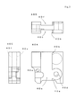
- Fig. 7 shows a configuration of the support block 40 as a component of the knitting yarn gripping device 10.
- the guide groove 40c has, at one side thereof, a penetrating hole 40d for the rotation shaft 29 and at the other side thereof, a penetrating hole 40e for the pivot 25.
- the support block has a guide groove 40f on the back side of the guide groove 40c. The same gripping mechanism as the gripping mechanism 11 can be formed by using the guide groove 40f.
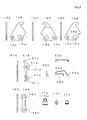
- Fig. 8 shows constructions of the nip pawls 13, 14, 15, the lock lever 51, the rod 16, the nip pivot 17a, and the rod pivot 17c, 17d as components of the knitting yarn gripping device 10.
- the operation pivot 17b is substantially the same in configuration as the nip pivot 17a.
- the nip pawls 13, 14, 15 have penetrating holes 13a, 14a, 15a, respectively, for the nip pivot 17a.
- the nip pawls 13, 15 have penetrating holes 13a, 15a, respectively, for the rod pivot 17c.
- the nip pawl 14 has a penetrating hole 14a for the rod pivot 17d.
- the lock lever 51 has a fitting hole 51d for the rod pivot 17d at its supporting portion 51a.
- a spring latch 51e for catching an end of the wire spring 52 is also provided between the supporting portion 51a and the lock releasing portion 51c.
- the wire spring 52 is provided with a urging portion 52a inserted in the spring latch 51e of the lock lever 51 to urge it and a base portion 52b inserted in the supporting portion 22g at the upper end portion of the operation plate 22 to be supported by it.
- the rod 16 has penetrating holes 16a, 16b for the operation pivot 17b and the rod pivots 17c, 17d to be penetrated, respectively.
Landscapes
- Engineering & Computer Science (AREA)
- Textile Engineering (AREA)
- Knitting Machines (AREA)
Abstract
Description
- The present invention relates to a knitting yarn gripping device of a flatbed knitting machine, arranged at a lateral side of a needle bed, for gripping a knitting yarn, and a control method of the same.
- In general, a
flatbed knitting machine 1 as is simplistically shown inFig. 9 has at least one pair ofneedle beds 2 which are arranged in front and back to face each other so as to define aneedle bed gap 3 therebetween. Front end portions of the knitting needles, not illustrated, are advanced from the front andback needle beds 2 into theneedle bed gap 3 and are retracted therefrom so that a knittedfabric 4 such as e.g. a sweater can be shaped into a final form while being knitted continuously. Aknitting yarn 6 is fed to the knitting needle on theneedle beds 2 from ayarn feeder 5 moved over theneedle bed gap 3. When the use of theknitting yarn 6 for the knittedfabric 4 is ended, theyarn feeder 5 is moved to a location on a lateral side of theneedle bed 2. The knittingyarn 6 extending from a final knitted loop in the knittedfabric 4 to theyarn feeder 5 is put in a slanted condition. - There is provided a
cutting device 7 for cutting theknitting yarn 6 extending from the knittedfabric 4 to theyarn feeder 5. The cutting of theknitting yarn 6 can allow smooth discharge of the knittedfabric 4 and can eliminate the need for splitting theknitting yarn 6 between the knittedfabrics 4 after discharged. Only the cutting results in floatation of a tip of the knitted yarn remaining on theyarn feeder 5 side, however. Gripping devices 8a, 8b are provided at an area on a lateral side of theneedle bed gap 3 into and from which the knitting needles are advanced from the front andback needle beds 2 and retracted, so that when theknitting yarn 6 extending to theyarn feeder 5 is cut by thecutting device 7, the open/close gripping portions 9a, 9b catch and hold an end of theknitting yarn 6 while gripping it (SeePatent Literature 1, for example). - In the holding mode, the gripping portions 9a, 9b are moved down to a lower limit of the stroke by the gripping devices 8a, 8b. When moved up to an upper point of the stroke from the lower limit, the gripping portions 9a, 9b can be opened in the middle of the upward movement. The gripping portions 9a, 9b opened catch the knitting yarns 6a, 6b in the course of moving up to the upper point of the stroke. Then, the gripping portions 9a, 9b are closed at the upper point of the stroke, to grip the knitting yarns 6a, 6b. After closed, the gripping portions 9a, 9b are moved downwards keeping the gripping of the knitting yarns 6a, 6b. When the next knitted
fabric 4 is knitted, the yarn feeders 5a, 5b are moved over theneedle bed gap 3 so that the knitting yarns 6a, 6b gripped at their ends by the gripping portions 9a, 9b can be fed to the knitting needles advanced into and retracted from theneedle bed gap 3. After the knitting yarns 6a, 6b are knitted into the knittedfabric 4, the gripping portions 9a, 9b can be opened to release the grip of the ends of the knitting yarns 6a, 6b. - The knitting yarns 6a, 6b are gripped by the gripping devices 8a, 8b not only when they are put in a standby condition until the next knitting but also when they are moved downward temporarily. For instance, when the knitted
fabric 4 such as a sweater is knitted in a tubular form, its body 4a and sleeve 4b are knitted in a tubular form in a body knitting area 2a and in a sleeve knitting area 2b at a lateral side of the body knitting area 2a, respectively. When the sleeve 4b is knitted after the yarn feeder 5b for theknitting yarn 6 used for knitting the body 4a is temporarily moved outward of theneedle bed 2, as represented in a full line, theknitting yarn 6 may possibly be knitted in together. This possible knit-in-together problem can be avoided for example when the gripping device 8b is first moved upward to catch theknitting yarn 6 by the opened gripping portion 9b, as represented in a full line, and then moved downward to close the gripping portion 9b, as represented in a two-dot chain line, so that the knitting yarn 6b can be pulled down, as represented in a two-dot chain line. - [Patent Literature 1] Japanese Examined Patent Publication No.
Hei 4-74463 - It is assumed in
Fig. 9 that when the inner gripping device 8a located close to theneedle bed 2 grips an end of the knitting yarn 6a extending from the yarn feeder 5a and is put in a standby condition, theknitting yarn 6 is pulled down temporarily by the outer gripping device 8b located away from theneedle bed 2. The yarn feeders 5a, 5b are disposed to feed the knitting yarns 6a, 6b to an area near a center part of theneedle bed gap 3. Due to this, when the gripping device 8b is lifted up to open its gripping portion 9b, so as to catch and grip theknitting yarn 6, the knitting yarn 6a gripped by the gripping device 8a is also lifted up, as represented in a two-dot chain line. The knitting yarn 6a may then be grazed and worn in the middle of being lifted up, to cause a yarn break, depending on material used for the knitting yarn 6a. Even if that does not cause the yarn break, as a result of the knitting yarn 6a being pulled overly, a tensile force may be increased overly so that the knitting yarn 6a may be dropped off from the gripping portion 9a. - It may be conceivable as a measure against these possible problems for the case where the inner gripping device 8a grips the knitting yarn 6a and is put in the standby condition that when the outer gripping device 8b is lifted up to catch another knitting yarn 6b, the inner gripping device 8a is also lifted up together. But, this involves a problem that even when the griping portion 9a of the gripping device 8a is closed and is put in the standby state, the gripping portion 9a closed may open in the middle of being lifted and release the knitting yarn 6a gripped. In the case where the
cutting device 7 cuts the knitting yarn 6b extending between the gripping portion 9b and the knittedfabric 4 and the outer gripping device 8b grips an end of the cut knitting yarn 6b preliminarily in advance of being brought into the standby condition, even when the inner gripping device 8a is lifted, the knitting yarn 6b is not lifted together. But, this involves a problem that a restriction is introduced on controlling those two different gripping devices 8a, 8b. - It is an object of the present invention to provide a knitting yarn gripping device of a flatbed knitting machine which is capable of preventing a yarn break or a yarn cast-off, even when the outer gripping device is lifted, with the inner gripping device in the standby condition while gripping the knitting yarn, and a control method of the same.
- The present invention provides a knitting yarn gripping device of a flatbed knitting machine provided with a plurality of gripping mechanisms, which are each provided, at an upper end thereof, with a gripping portion for gripping a knitting yarn extending from a yarn feeder and are arranged in order between a movement zone where the yarn feeder is moved laterally of a needle bed and the needle bed, with a needle bed side as an inner side and a movement zone side as an outer side, each gripping mechanism comprising:
- a mounting plate which is driven to move up and down between an upper limit and a lower limit of a predetermined stroke and has, at an upper end portion thereof, a gripping portion mounted in a openable and closable manner,
- an operation plate which is disposed in an overlying relation with the mounting plate and has, at an upper end portion, with an operation portion for opening and closing the gripping portion, the operating plate being structured so that it can open the gripping portion when a distance for the operation plate to be lowered relative to the mounting plate exceeds an opening reference,
- a tension spring which is provided between the mounting plate and the operation plate for urging the operation plate in a direction in which the distance for the operation plate to be lowered relative to the mounting plate decreases,
- an open/close lock mechanism which is provided between the mounting plate and the operation plate, so that when the distance for the operation plate to be lowered relative to the mounting plate exceeds the opening reference within a predetermined lower limit range of the stroke of the mounting plate, the open/close lock mechanism can operate to lock the operation plate so as to prevent the distance lowered from decreasing below the opening reference and can release the lock within a predetermined upper limit range of the stroke of the mounting plate, and
- an operation lock mechanism which operates to lock the operation plate to prevent the upward movement while the mounting plate is moving down to the lower limit range and release the lock after the mounting plate is moved up in the state of the operation plate being locked and then the lock by the open/close lock mechanism is initiated,
- wherein when the knitting yarn extending from the yarn feeder moved to the movement zone is caught or gripped to be held by the inner gripping mechanism, a position to which the mounting plate is moved down is limited to a predetermined standby position upper in level than the lower limit range,
- when the mounting plate is moved up and down by the outer gripping mechanism, following opening-and-closing and gripping procedures that the mounting plate is moved down to the lower limit area, whereby the operation plate is locked by the operation lock mechanism to prevent the upward movement; then the mounting plate is moved up to open the gripping portion in the middle of moving upward and also lock the open/close lock mechanism; then the mounting plate is moved up to the upper limit area, whereby the lock of the open/close lock mechanism is released and the knitting yarn is caught or gripped by the gripping portion closed; and then the gripping portion is moved down, at least the inner gripping mechanism controls the mounting plate in such a manner as to simultaneously move up from the standby position and then move down, and
- the gripping mechanism further comprises control means for controlling the mounting plate of the inner gripping mechanism in such a manner as to move up and down, following the opening-and-closing and gripping procedures, when the knitting yarn is caught or gripped by the inner gripping mechanism.
- The present invention is characterized in that the gripping mechanism further comprises a grip lock mechanism which is disposed at an upper portion of the mounting plate and is so structured that when the lock by the open/close lock mechanism is released and then the gripping portion is closed, the gripping portion is locked in a partly closed state so that it can be kept at a stage before gripping the knitting yarn, and then the lock of the gripping portion is released in the middle of the mounting plate being moved down to the standby position, whereby the gripping portion is closed to grip the knitting yarn.
- The present invention is characterized in that the gripping mechanism further comprises:
- a support block having a guide groove for guiding upward and downward shift of the mounting plate and the operation plate, wherein the guide groove has, at a lower end thereof, a bottom surface via which the lock of the open/close lock mechanism is released and has, at an upper end thereof, a slanted surface via which the lock of the grip lock mechanism is released, and
- a lock lever included in the grip lock mechanism and having a support portion which is pivotally supported by the gripping portion, a locking portion which projects obliquely outwardly from the support portion to lock the gripping portion in its partly closed state, and a lock releasing portion which extends vertically downwardly of the support portion, wherein when abutting with the slanted surface at the upper end of the guide groove of the support block, the lock releasing portion is pivoted so that the lock of the gripping portion by the locking portion is released and thereby is moved down together with the downward movement of the mounting plate through the guide groove.
- Also, the present invention provides a control method of a knitting yarn gripping device of a flatbed knitting machine provided with a plurality of gripping mechanisms, which are each provided, at an upper end thereof, with a gripping portion for gripping a knitting yarn extending from a yarn feeder and are arranged in order between a movement zone where the yarn feeder is moved laterally of a needle bed and the needle bed, with a needle bed side as an inner side and a movement zone side as an outer side,
- each gripping mechanism is preset so that
- it can be driven to move up and down between an upper limit and a lower limit of a predetermined stroke,
- it can be locked within a predetermined lower limit range of the stroke in a state of the gripping portion being opened, and
- the lock can be released within a predetermined upper limit range of the stroke, whereby the gripping portion is closed to catch the knitting yarn,
- The prevent invention is characterized in that a distance for the inner gripping mechanism to move up from the standby position is set to be lower in level by only a predetermined difference than a distance for the outer gripping mechanism to move up, following the opening-and-closing and gripping procedures, so as to open the gripping portion.
- According to the knitting yarn gripping device of the present invention, the mounting plate is driven to move up and down between an upper limit and a lower limit of a predetermined stroke and the gripping portion is opened and closed according to a distance for the operation plate to be moved down relative to the mounting plate. The mounting plate has, at an upper end portion thereof, the gripping portion mounted in an openable and closable manner. The operation plate actuated to open and close the gripping portion is disposed in an overlying relation with the mounting plate. The mounting plate and the operation plate are pulled each other by the tension spring and can be locked by the open/close lock mechanism to keep the gripping portion in the opened state. When the gripping portion is opened, it is required that the mounting plate is moved down to the lower limit range and the operation plate is locked by the operation lock mechanism, first, and then, the mounting plate is moved up. When the mounting plate is moved up to the upper limit range, the lock of the open/close lock mechanism is released so that the gripping portion can be closed to catch or grip the knitting yarn. Then, the mounting plate is moved down to the predetermined standby position which is above the lower limit area. Following these opening-and-closing and gripping procedures, the gripping portion can be moved up and down and opened and closed, to catch or grip the knitting yarn.
The control means controls the mounting plates in such a manner that when the mounting plate is moved up and down by the outer gripping mechanism, following the opening-and-closing and gripping procedures, whereby the knitting yarn is caught or gripped by the gripping portion, the mounting plate of the inner gripping mechanism can be simultaneously moved up together from the standby position and then be moved down. Even when the inner gripping mechanism is moved up from the standby position, the gripping portion is not opened. This can avoid a possible problem that the gripping portion may be moved up in the state of gripping the knitting yarn to cause an overly increased tension of the knitting yarn that may cause a yarn break or a yarn cast-off. - According to the present invention, even when the lock by the open/close lock mechanism is released, the gripping portion can be locked, when being in the middle of being closed, by the grip lock mechanism, to prevent the knitting yarn caught from being gripped. This can produce the result that even when the gripping portion is in the middle of being moved down, the knitting yarn can be supplied additionally from the yarn feeder to avoid an overly increased tension of the knitting yarn that may cause a close stitch or a yarn break on the knitted fabric side.
- According to the present invention, even when the lock by the grip lock mechanism is released by bringing the lock releasing portion of the lock lever into abutment with the slanted surface at the upper end of the guide groove of the support block, the lock releasing portion can be moved down through the guide groove to allow the mounting plate to move down further. Since a stroke for allowing the mounting plate to move down can be added after the lock by the grip lock mechanism is released, the gripping portion even when moved up can be prevented from being opened during the downward movement to the standby position during which the operation plate is not locked by the operation lock mechanism. When the operation plate is moved down to the position where it is locked by the operation lock mechanism, the gripping portion is put in the state in which it can be opened when moved up following the opening-and-closing and gripping procedures.
- Further, according to the present invention, when the outer gripping mechanism is moved up to catch the knitting yarn in the condition in which the knitting yarn extending from the yarn feeder to move in a lateral side of the needle bed is gripped by the inner gripping mechanism, the inner gripping mechanism is also moved up together. This can prevent exertion of an excess tension on the knitting yarn gripped by the inner gripping mechanism, to prevent a yarn break or a yarn cast-off. Since the grip by the inner gripping mechanism is performed at the predetermined standby position which is above the lower limit range, the inner gripping mechanism may be moved up therefrom to keep the grip or may alternatively be moved down therefrom first and then moved up, following the opening-and-closing and gripping procedures, to open the gripping portion. Thus, these two different modes can be selectively used, according to need.
- According to the present invention, a distance for the inner gripping mechanism to move up from the standby position is set to be lower in level by only a predetermined difference than a distance for the outer gripping mechanism to move up, following the opening-and-closing and gripping procedures, so as to open the gripping portion. When this level difference is predetermined in such a manner that the catching and gripping motion of the outer gripping portion opened is not hindered by an upper end of the inner gripping portion closed, the knitting yarn can be reliably caught and gripped by the outer gripping portion. Even in the case where the knitting yarn gripped by the gripping portion of the inner gripping mechanism is caught by the outer gripping portion, when the both gripping mechanisms are moved down to the standby positions equal in level to each other, the knitting yarn extending between the both gripping portions can be slacken off, whereby exertion of an overly increased tension on the knitting yarn can be prevented when one of the gripping portions is moved down to open the gripping portion following the opening-and-closing and gripping procedures.
-
- [
Fig.1] Fig. 1 is a partial front view of a flatbed knitting machine, diagrammatically showing a schematic construction of a knittingyarn gripping device 10 of a certain embodiment of the present invention. - [
Fig.2] Fig. 2 shows a front view and a part of a rear view of the knittingyarn gripping device 10 ofFig. 1 , showing the state in which agripping mechanism 11 is moved down to a lower limit of the stroke and a grippingportion 12 is closed. - [
Fig.3] Fig. 3 shows a front view, a left side view, a plan view, and a part of a rear view of the knittingyarn gripping device 10 ofFig. 1 , showing the state in which even when a mountingplate 18 is moved upward, an operatingplate 22 is locked to prevent the upward movement by anoperation lock mechanism 24 and also the grippingportion 12 is opened and locked by an open/close lock mechanism 19. - [
Fig.4] Fig. 4 shows a front view and a part of a rear view of the knittingyarn gripping device 10 ofFig. 1 , showing the state in which the lock of the open/close lock mechanism 19 is released and also the grippingportion 12 is locked by agrip lock mechanism 50 in the middle of being closed. - [
Fig.5] Fig. 5 shows a front view and a part of a rear view of the knittingyarn gripping device 10 ofFig. 1 , showing the state in which the mountingplate 18 is moved down to a standby position and the locks of the open/close lock mechanism 19, theoperation lock mechanism 24, and thegrip lock mechanism 50 are all released. - [
Fig.6] Fig. 6 shows a front view and a left side view, showing constructions of the mountingplate 18, a hook member 20a, theoperation plate 22, and apivot pawl 26 as components of the knittingyarn gripping device 10 ofFig. 1 . - [
Fig.7] Fig. 7 shows a plan view, a left side view, and a front view, showing a construction of asupport block 40 as a component of the knittingyarn gripping device 10 ofFig. 1 . - [
Fig. 8] Fig. 8 shows a left side view and a front view showing constructions of a nippawls lock lever 51, arod 16, a nip pivot 17a, an operation pivot 17b, and a rod pivot 17c as components of the knittingyarn gripping device 10 ofFig. 1 , and a plan view, a left side view, and a front view, showing a configuration of awire spring 52 as the component. - [
Fig.9] Fig. 9 is a partial front view, diagrammatically showing a schematic construction of a conventionalflatbed knitting machine 1 having agripping device 8. - In the following, a certain embodiment of the present invention is described with reference to
Figs. 1-8 . In the embodiment, corresponding parts to the parts described inFig. 9 are labeled the same reference characters, for avoidance of redundancy of explanation. In the description ofFigs. 1-8 , explanation on like-numbered parts corresponding to the parts previously explained may be omitted, for avoidance of redundancy of explanation. Alphabets A, B, C, and D added to the reference numerals throughout the drawingfigures 2-8 indicate a front construction, a part of a rear construction, a left-side construction, and a plan construction, respectively. It is to be noted that the front direction corresponds to a lateral direction with respect to the flatbed knitting machine. -
Fig. 1 diagrammatically shows a part of the front view of a schematic construction of a knittingyarn gripping device 10 of a certain embodiment of the present invention as a part of a front view of aflatbed knitting machine 30. The knittingyarn gripping device 10 is provided, at one lateral side of aneedle bed 2, with twogripping mechanisms 11a, 11b having basically the same construction as thegripping device 8 ofFig. 9 and acutting device 7. The knittingyarn gripping device 10 may be provided with the same construction at the other lateral side of theneedle bed 2 as well. Thegripping mechanisms 11a, 11b have, at upper ends thereof, gripping portions 12a, 12b, and are driven to move up and down via adrive unit 32 which is controlled by acontroller 31 which is control means for controlling theflatbed knitting machine 30. - The
controller 31 controls at least the inner gripping mechanism 11a so that the standby position where the gripping portion 12a is closed to grip an end of a knitting yarn 6a and stands in readiness can be set higher than a lower limit of a lifting-and-lowering stroke of the gripping mechanism 11a. A height of the standby position is set to be within such a range that a carriage can move in reciprocation along the needle bed without being interrupted. In the case of the carriage having a pressing mechanism, such as a stitch presser, for pressing a knitted fabric downward in theneedle bed gap 3, the standby position is set so that such a pressing mechanism can also move without being interrupted. - The gripping mechanism 11a opens its gripping portion 12a when moving first downward to a lower limit than the standby position and then turns around to move upward. When the gripping mechanism 11a moves directly from the standby position, the gripping portion 12a is kept in the closed state. Thus, when the outer
gripping mechanism 11b is moved up to catch the knitting yarn 6b by its gripping portion 12b, the gripping mechanism 11a can also be moved up while gripping the knitting yarn 6a by its gripping portion 12a. When only the gripping portion 12a of the inner gripping mechanism 11a is moved upward to catch the knitting yarn 6a and then moved downward for gripping operation, since the outergripping mechanism 11b is not needed to be moved upward, only the gripping mechanism 11a is operated singularly. - As mentioned above, when the outer gripping portion 12b is moved up to catch and grip the knitting yarn 6b in the state in which the inner gripping mechanism 12a grips an end of the knitting yarn 6a in its standby position, the inner gripping portion 12a is also moved up. At this time, when the inner gripping portion 12a is moved up to a position equal in level to the outer gripping portion 12b, since the inner gripping portion 12a is closed, the inner gripping portion 12a lifts the knitting yarn 6b at its upper end. As a result of this, it becomes hard for the outer griping portion 12b to catch the knitting yarn 6b. Also, the knitting yarn 6a gripped by the inner gripping portion 12a is gripped by the outer gripping portion 12b as well. Consequently, an upper position to which the inner gripping portion 12a is moved up is set to be lower by only a height difference H than an upper position to which the outer gripping portion 12b is moved up, in order not interrupt the gripping motion of the outer gripping portion 12b to open at an outer side so as to catch and grip the knitting yarn 6b. The height difference H is set to the order of e.g. 10mm. The height difference H produces the result that when both gripping portions 12a, 12b gripping the knitting yarn 6a are lowered to the standby positions equal in level to each other, the knitting yarn 6a extending between the gripping portions 12a, 12b is put in a slacked state. This slackness can prevent exertion of an excessive tensile force on the knitting yarn 6a even when only one of the gripping portions 12a, 12b is lowered to a position lower than the standby position and then returned around to move up to release the knitting yarn 6a.
- Even when three or more
gripping mechanisms 11 are provided, the inner gripping mechanism can be moved up together with the outer griping mechanism in the same manner. The upward movement of the inner gripping mechanism associated with the upward movement of the outer gripping mechanism may always be introduced whether the inner gripping mechanism grips the knitting yarn or not.
Fig. 2 shows the state in which thegripping mechanism 11 is moved down to a lower limit of the stroke and the grippingportion 12 is closed. The grippingportion 12 is provided with three nippawls pawls portion 12 is opened and closed in their cooperation with the inside nippawl 14. The three nippawls rods 16 are connected at their lower end portions to each other through an operation pivot 17b. The nippawls rod 16 are connected through a rod pivot 17c. Thenip pawl 14 and the upper end portion of therod 16 are connected through a rod pivot 17d. The nippawls rods 16 form a linkage mechanism to allow the degree of opening and closing of the front end portions of the gripping portion to vary according to a distance between the nip pivot 17a and the operation pivot 17b. - The nip pivot 17a is fixed to the mounting
plate 18 at a location near an upper end thereof. The mountingplate 18 is nearly in the form of a vertically extending plate and has a slot 18a formed in an intermediate part thereof. Also, the mountingplate 18 has a rack 18b formed at one lateral side thereof and has a cam recess 18c formed at the other lateral side thereof. Ahook 20 of the open/close lock mechanism 19 is mounted on the mountingplate 18 at a location near a lower end portion thereof. Thehook 20 has a nearly L-shaped form and is pivotally supported by a hook pivot 20a at a front end thereof on the long side. The long side of thehook 20 is pushed from the lateral side by apush spring 21 and is urged in a direction of a front end 20b of the hook on the short side. - The operation pivot 17b is fixed to the
operation plate 22 at a location near the upper end of the same. Theoperation plate 22 is connected to the mountingplate 18 through atension spring 23. Thetension spring 23 is accommodated in a space formed by a slot 22a formed in an intermediate portion of theoperation plate 22 and the slot 18a of the mountingplate 18. Theoperation plate 22 is so disposed as to lay over the mountingplate 18 and has a notch 22b formed at a lateral side thereof on the side on which the cam recess 18c of the mountingplate 18 is formed. The cam recess 18c and the notch 22b are provided in order that apivot pawl 26 pivotable about apivot 25 can be operated by anoperation lock mechanism 24. When aroller 27 mounted on thepivot pawl 26 is guided by the cam recess 18c so that a pawl portion 26a at the front end of thepivot pawl 26 is fitted in the notch 22b, theoperation plate 22 is locked to prevent following upward movement with the upward movement of the mountingplate 18. The mountingplate 18 and theoperation plate 22 are both locked by thehook 20 of the open/close lock mechanism 19 as well. - The rack 18b of the mounting
plate 18 formed at the lateral side is meshed with apinion 28. The mountingboard 18 and thepinion 28 are main components of adrive unit 32 ofFig. 1 . When arotation shaft 29 of thepinion 28 is rotationally driven by a motor, the mountingplate 18 can be shifted in vertical position. When the mountingplate 18 is moved up and down, the grippingmechanism 11 moves up and down in response to the movement of the mountingplate 18. Since thetension spring 23 urges theoperation plate 22 in a direction in which it is moved closer to the mountingplate 18, the grippingportion 12 is urged in a direction in which it is closed via the linkage mechanism. - The mounting
plate 18 and theoperation plate 22 are shifted in vertical position in such a manner as to slide over asupport block 40. Thesupport block 40 is mounted on a frame at a lateral side of the needle bed of the flatbed knitting machine. Thesupport block 40 supports thereon thepivot 25 of thepivot pawl 26 and therotation shaft 29. Thesupport block 40 is provided, at a lower portion thereof, with an abutment portion 40a. When the front end 20b of thehook 20 abuts with the abutment portion 40a, the interlock between the mountingplate 18 and theoperation plate 22 is released by thehook 20. - The knitting
yarn gripping device 10 includes agrip lock mechanism 50 for locking the linkage mechanism in the middle of the grippingportion 12 being closed, to only keep the grippingportion 12 in the stage of catching the knitting yarn prior to gripping it. Thegrip lock mechanism 50 includes alock lever 51 and awire spring 52. Thelock lever 51 is urged by thewire spring 52 in the counterclockwise direction, when viewed from thefront configuration 10A. Thelock lever 51 is pivotally supported by the rod pivot 17b by which thenip pawl 14 and the upper end of therod 16 are connected. In order to release the lock of the linkage mechanism by thelock lever 51, thesupport block 40 is provided, at its upper portion, with a slanted surface 40b. The abutment portion 40a and the slanted surface 40b are respectively provided at a lower portion of a guide groove 40c and at an upper portion of the guide groove 40c in which the mountingplate 18 and theoperation plate 22 are accommodated in the overlying relation with each other. -
Fig. 3 shows the state in which the mountingplate 18 is moved upward from the state ofFig. 2 , so that the grippingportion 12 is opened and locked by the open/close lock mechanism 19. When the mountingplate 18 is moved up from the state ofFig. 2 , theoperation plate 22 urged by means of thetension spring 23 is moved up together. Thepivot pawl 26 is urged by means of a leaf spring, not illustrated, so that its pawl portion 26a can be pressed against the lateral side of theoperation plate 22. Theroller 27 provided on thepivot pawl 26 is fitted in the cam recess 18c of theoperation plate 18 so that the pawl portion 26a of thepivot pawl 26 can be fitted into the notch 22b. When the notch 22b reaches the position of the pawl portion 26a of thepivot pawl 26 with the upward movement of theoperation plate 22, the pawl portion 26a is engaged in the notch 22b and thereby theoperation plate 22 is locked to stop the upward movement. When the mountingplate 18 is moved upward with theoperation plate 22 remaining at rest, theoperation plate 22 is lowered relative to the mountingplate 18. As the distance between the nip pivot 17a at the upper end portion of the mountingplate 18 and the operation pivot 17b at the upper end portion of theoperation plate 22 is increased, the grippingportion 12 is opened. When the distance lowered exceeds an opening reference position at which the abutment portion 22c at the lower end of theoperation plate 22 is lowered below an intermediate portion 20c of the L-shapedhook 20 between the long side thereof and the short side thereof, thehook 20 urged by means of thepush spring 21 is pivoted so that its intermediate portion 20c is positioned above the abutment portion 22c. - When the mounting
plate 18 is moved up further, theroller 27 is disengaged from the cam recess 18c and thepivot pawl 26 is pivoted in the clockwise direction, so that the pawl portion 26a is disengaged from the notch 22b of theoperation plate 22. As a result of this, the lock against theoperation plate 22 by theoperation lock mechanism 24 is released and theoperation plate 22 is moved upward by the urging force of thetension spring 23 so as to decrease the distance for theoperation plate 22 to be lowered relative to the mountingplate 18. When the abutment portion 22c moving up abuts with the intermediate portion 20c of thehook 20, the upward movement of theoperation place 22 is stopped and is put in the state of being locked by the open/close lock mechanism 19. When the mountingplate 18 is moved upward until the locked state is released, theoperation plate 22 is also moved up together, with the grippingportion 12 remaining opened. - The
support block 40 has, on the back side, substantially the same guide groove as the guide groove 40c. Like grippingmechanism 11 is accommodated in that guide groove on the back side, for upward and downward drive. In this regard, however, to allow the drive on the back side, apinion 58 and arotation shaft 59 are disposed at locations different from the locations where thepinion 28 and therotation shaft 59 are disposed. Thus, the knittingyarn gripping portion 10 ofFig. 1 is provided with twogripping mechanisms 11a, 11b for asingle support block 40. -
Fig. 4 shows the state in which the lock of the open/close lock mechanism 19 is released and also the grippingportion 12 is locked by agrip lock mechanism 50 in the middle of being closed. As shown inFig. 3 , when the mountingplate 18 and theoperation plate 22 are interlocked by the open/close lock mechanism 19 and then the mountingplate 18 is moved upward, the front end 20b of thehook 20 abuts with the abutment portion 40a at the lower portion of thesupport block 40. As a result of this, thehook 20 is pivoted in the clockwise direction to disengage the intermediate portion 20c from the abutment portion 22c of theoperation plate 22, so that the lock is released. Since theoperation plate 22 is biased by thetension spring 23 so that the distance for theoperation plate 22 to be lowered relatively from the mountingplate 18 can be decreased, theoperation plate 22 is moved upward. As a result of this, the distance between the nip pivot 17a and the operation pivot 17b is narrowed, so that the grippingportion 12 is closed. - In the illustrated embodiment, there is provided a
grip lock mechanism 50 for preventing the grippingportion 12 from being closed completely. Alock lever 51 of thegrip lock mechanism 50 has a locking portion 51b extending obliquely outwardly from a support portion 51a supported by the rod pivot 17d. The locking portion 51b is brought into abutment with a stepped portion 15b of thenip pawl 15, whereby the grippingportion 12 is locked to prevent the grippingportion 12 from being closed completely. When the lock of the open/close lock mechanism 19 is released, the grippingportion 12 is closed completely unless thegrip lock mechanism 50 is used. - A catching space 50a is formed between front ends of the nip pawls 13 and 15, and 14 locked by the
grip lock mechanism 50, so that the knitting yarn can be pulled down in state of being only caught without being gripped. Since the grippingportion 12 does not grip the knitting yarn, the knitting yarn can move from the yarn feeder to a zone from the grippingportion 12 to the knitted fabric through the catching space 50a, to be additionally supplied to that zone, even in the middle of being pulled down. This can prevent exertion of an excess tension on the knitting yarn extending between the grippingportion 12 and the knitted fabric, thus preventing occurrence of a close stitch or a yarn break even after the grippingportion 12 is closed and grips the knitting yarn, after lowered. -
Fig. 5 shows the state in which the mountingplate 18 is moved down to the standby position and the locks of the open/close lock mechanism 19, theoperation lock mechanism 24, and thegrip lock mechanism 50 are all released. The lock of thegrip lock mechanism 50 inFig. 4 is released when alock releasing portion 51c provided at a lower end of thelock lever 51 is brought into abutment with the slanted surface 40b of thesupport block 40. Thelock lever 51 is pivoted about the rod pivot 17d at the support portion 51a in a direction in which thelock releasing portion 51c is inserted in the guide groove 40c. As a result of this, the locking portion 51b is disengaged from the stepped portion 15b of thenip pawl 15, so that the grippingportion 12 can be closed completely to grip the knitting yarn. - As mentioned above, when the mounting
plate 18 is moved down to a lower limit area, including the lower limit shown inFig. 2 , where theoperation plate 22 can be locked by theoperation lock mechanism 24 to prevent the upward movement, it can open the grippingportion 12 in the middle of moving upward as shown inFig. 3 and can also lock the open/close lock mechanism 19. By the mountingplate 18 moving up to an upper limit area as shown inFig. 4 , the lock of the open/close lock mechanism 19 is released and theknitting yarn 6 is caught by the grippingportion 12 closed. In the case that thegrip lock mechanism 50 is not provided, the lock of the open/close lock mechanism 19 is released and theknitting yarn 6 is gripped by the grippingportion 12. Following these opening-and-closing and gripping procedures, the grippingportion 12 can be driven to catch or grip theknitting yarn 6, while being lowered. - When the mounting
plate 18 is lifted up from the standby position without following the opening-and-closing and gripping procedures, theoperation plate 22 is not locked by theoperation lock mechanism 24. Consequently, the grippingportion 12 can be moved upward in the closed state. Also, when the downward movement of the mountingplate 18 is limited to a range within which the mountingplate 18 is positioned above the standby position and the lock of thegrip lock mechanism 50 is not released by the slanted surface 40b, the grippingportion 12 can be placed in standby in the catch mode in which the grippingportion 12 is not closed completely, leaving the catching space 50a, as is the case withFig. 4 . When the mountingplate 18 is moved up from this condition, the grippingportion 12 can be moved up, with the catching space 50a kept intact. In other words, the grippingportion 12 can be placed in the standby condition while holing the knitting yarn by catching or gripping it and can also keep that holding state intact even when moved up from the standby condition. -
Fig. 6 shows constructions of the mountingplate 18, thehook 20, theoperation plate 22, and thepivot pawl 26 as components of the knittingyarn gripping device 10. The mountingplate 18 has a screw hole 18d formed in an upper end portion thereof for mounting the nip pivot 17a. It also has a fitting hole 18e for spring peg use, formed at a location below the screw hole 18d and above the slot 18a, for supporting an upper end of thetension spring 23. A screw hole 18f for mounting the hook pivot 20a of thehook 20 is provided below the slot 18a. The mountingplate 18 has, at a lower end portion thereof, a spring latch 18g for catching a lateral side of thepush spring 21. It also has, at an upper portion thereof, a slot 18h formed between the screw hole 18d and the fitting hole 18e. - The
operation plate 22 has a stepped portion, formed at an upper end portion thereof, for receiving therod 16 and a screw hole 22d for mounting the operation pivot 17b. The slot 18h of the mountingplate 18 is provided for escaping a tip of the threaded portion of the operation pivot 17b, which is screwed in the screw hole 22d and on which the tworods 16 are pivotally mounted, being projected to the back side. A fitting hole 22e for the spring peg supporting the lower end of thetension spring 23 is provided below the slot 22a. Theoperation plate 22 has a void 22f formed at a lateral side of the upper end portion, for accommodating thelock releasing portion 51c of thelock lever 51. It also has, at its upper end, a supporting portion 22g for supporting thewire spring 52. - The
hook 20 has a penetrating hole 20d for the hook pivot 20a and an insertion hole 20e for receiving a lateral side of thepush spring 21. Thepivot pawl 26 also has a penetrating hole 26b for thepivot 25. -
Fig. 7 shows a configuration of thesupport block 40 as a component of the knittingyarn gripping device 10. The guide groove 40c has, at one side thereof, a penetrating hole 40d for therotation shaft 29 and at the other side thereof, a penetrating hole 40e for thepivot 25. The support block has a guide groove 40f on the back side of the guide groove 40c. The same gripping mechanism as the grippingmechanism 11 can be formed by using the guide groove 40f. -
Fig. 8 shows constructions of the nippawls lock lever 51, therod 16, the nip pivot 17a, and the rod pivot 17c, 17d as components of the knittingyarn gripping device 10. The operation pivot 17b is substantially the same in configuration as the nip pivot 17a. The nippawls pawls nip pawl 14 has a penetrating hole 14a for the rod pivot 17d. Thelock lever 51 has a fitting hole 51d for the rod pivot 17d at its supporting portion 51a. A spring latch 51e for catching an end of thewire spring 52 is also provided between the supporting portion 51a and thelock releasing portion 51c. Thewire spring 52 is provided with a urging portion 52a inserted in the spring latch 51e of thelock lever 51 to urge it and a base portion 52b inserted in the supporting portion 22g at the upper end portion of theoperation plate 22 to be supported by it. Therod 16 has penetrating holes 16a, 16b for the operation pivot 17b and the rod pivots 17c, 17d to be penetrated, respectively. -
- 10
- Knitting yarn gripping device
- 11
- Gripping mechanism
- 12
- Gripping portion
- 13, 14, 15
- Nip pawl
- 18
- Mounting plate
- 19
- Open/close lock mechanism
- 20
- Hook
- 22
- Operation plate
- 23
- Tension spring
- 24
- Operation lock mechanism
- 26
- Pivot pawl
- 28
- Pinion
- 30
- Flatbed knitting machine
- 31
- Controller
- 40
- Support block
- 50
- Grip lock mechanism
- 51
- Lock lever
when the outer gripping mechanism is moved up and down, following opening-and-closing and gripping procedures that the outer gripping mechanism is moved down to the lower limit area and is locked in the opened state of the gripping portion; then is moved up to the upper limit area, whereby the lock is released to close the gripping portion so as to catch or grip the knitting yarn by it; and then the gripping portion is moved down, at least the inner gripping mechanism is controlled in such a manner as to simultaneously move up from the standby position and then move down, and
when the knitting yarn is caught and gripped by the inner gripping mechanism, the inner gripping mechanism is controlled in such a manner as to move up and down, following the opening-and-closing and gripping procedures.
Claims (5)
- A knitting yarn gripping device of a flatbed knitting machine provided with a plurality of gripping mechanisms, which are each provided, at an upper end thereof, with a gripping portion for gripping a knitting yarn extending from a yarn feeder and are arranged in order between a movement zone where the yarn feeder is moved laterally of a needle bed and the needle bed, with a needle bed side as an inner side and a movement zone side as an outer side,
each gripping mechanism comprising:a mounting plate which is driven to move up and down between an upper limit and a lower limit of a predetermined stroke and has, at an upper end portion thereof, a gripping portion mounted in a openable and closable manner,an operation plate which is disposed in an overlying relation with the mounting plate and has, at an upper end portion, with an operation portion for opening and closing the gripping portion, the operating plate being structured so that it can open the gripping portion when a distance for the operation plate to be lowered relative to the mounting plate exceeds an opening reference,a tension spring which is provided between the mounting plate and the operation plate for urging the operation plate in a direction in which the distance for the operation plate to be lowered relative to the mounting plate decreases,an open/close lock mechanism which is provided between the mounting plate and the operation plate, so that when the distance for the operation plate to be lowered relative to the mounting plate exceeds the opening reference within a predetermined lower limit range of the stroke of the mounting plate, the open/close lock mechanism can operate to lock the operation plate so as to prevent the distance lowered from decreasing below the opening reference and can release the lock within a predetermined upper limit range of the stroke of the mounting plate, andan operation lock mechanism which operates to lock the operation plate to prevent the upward movement while the mounting plate is moving down to the lower limit range and release the lock after the mounting plate is moved up in the state of the operation plate being locked and then the lock by the open/close lock mechanism is initiated,wherein when the knitting yarn extending from the yarn feeder moved to the movement zone is caught or gripped to be held by the inner gripping mechanism, a position to which the mounting plate is moved down is limited to a predetermined standby position upper in level than the lower limit range,when the mounting plate is moved up and down by the outer gripping mechanism, following opening-and-closing and gripping procedures that the mounting plate is moved down to the lower limit area, whereby the operation plate is locked by the operation lock mechanism to prevent the upward movement; then the mounting plate is moved up to open the gripping portion in the middle of moving upward and also lock the open/close lock mechanism; then the mounting plate is moved up to the upper limit area, whereby the lock of the open/close lock mechanism is released and the knitting yarn is caught or gripped by the gripping portion closed; and then the gripping portion is moved down, at least the inner gripping mechanism controls the mounting plate in such a manner as to simultaneously move up from the standby position and then move down, andthe gripping mechanism further comprises control means for controlling the mounting plate of the inner gripping mechanism in such a manner as to move up and down, following the opening-and-closing and gripping procedures, when the knitting yarn is caught or gripped by the inner gripping mechanism. - The knitting yarn gripping device of the flatbed knitting machine according to Claim 1, wherein the gripping mechanism further comprises a grip lock mechanism which is disposed at an upper portion of the mounting plate and is so structured that when the lock by the open/close lock mechanism is released and then the gripping portion is closed, the gripping portion is locked in a partly closed state so that it can be kept at a stage before gripping the knitting yarn, and then the lock of the gripping portion is released in the middle of the mounting plate being moved down to the standby position, whereby the gripping portion is closed to grip the knitting yarn.
- The knitting yarn gripping device of the flatbed knitting machine according to Claim 2, wherein the gripping mechanism further comprises:a support block having a guide groove for guiding upward and downward shift of the mounting plate and the operation plate, wherein the guide groove has, at a lower end thereof, a bottom surface via which the lock of the open/close lock mechanism is released and has, at an upper end thereof, a slanted surface via which the lock of the grip lock mechanism is released, anda lock lever included in the grip lock mechanism and having a support portion which is pivotally supported by the gripping portion, a locking portion which projects obliquely outwardly from the support portion to lock the gripping portion in its partly closed state, and a lock releasing portion which extends vertically downwardly of the support portion, wherein when abutting with the slanted surface at the upper end of the guide groove of the support block, the lock releasing portion is pivoted so that the lock of the gripping portion by the locking portion is released and thereby is moved down together with the downward movement of the mounting plate through the guide groove.
- A control method of a knitting yarn gripping device of a flatbed knitting machine provided with a plurality of gripping mechanisms, which are each provided, at an upper end thereof, with a gripping portion for gripping a knitting yarn extending from a yarn feeder and are arranged in order between a movement zone where the yarn feeder is moved laterally of a needle bed and the needle bed, with a needle bed side as an inner side and a movement zone side as an outer side,
each gripping mechanism is preset so that
it can be driven to move up and down between an upper limit and a lower limit of a predetermined stroke,
it can be locked within a predetermined lower limit range of the stroke in a state of the gripping portion being opened, and
the lock can be released within a predetermined upper limit range of the stroke, whereby the gripping portion is closed to catch the knitting yarn,
wherein when the knitting yarn extending from the yarn feeder moved to the movement zone at a lateral side of the needle bed is caught or gripped to be held by the inner gripping mechanism, a position to which the inner gripping mechanism is moved down is limited to a predetermined standby position upper in level than the lower limit range,
when the outer gripping mechanism is moved up and down, following opening-and-closing and gripping procedures that the outer gripping mechanism is moved down to the lower limit area and is locked in the opened state of the gripping portion; then is moved up to the upper limit area, whereby the lock is released to close the gripping portion so as to catch or grip the knitting yarn by it; and then the gripping portion is moved down, at least the inner gripping mechanism is controlled in such a manner as to simultaneously move up from the standby position and then move down, and
when the knitting yarn is caught and gripped by the inner gripping mechanism, the inner gripping mechanism is controlled in such a manner as to move up and down, following the opening-and-closing and gripping procedures. - The control method of the knitting yarn gripping device of the flatbed knitting machine according to Claim 4, wherein a distance for the inner gripping mechanism to move up from the standby position is set to be lower in level by only a predetermined difference than a distance for the outer gripping mechanism to move up, following the opening-and-closing and gripping procedures, so as to open the gripping portion.
Applications Claiming Priority (1)
| Application Number | Priority Date | Filing Date | Title |
|---|---|---|---|
| JP2009299270A JP5286250B2 (en) | 2009-12-29 | 2009-12-29 | Knitting yarn gripping device of flat knitting machine and control method thereof |
Publications (2)
| Publication Number | Publication Date |
|---|---|
| EP2341171A1 true EP2341171A1 (en) | 2011-07-06 |
| EP2341171B1 EP2341171B1 (en) | 2014-12-17 |
Family
ID=43836826
Family Applications (1)
| Application Number | Title | Priority Date | Filing Date |
|---|---|---|---|
| EP10016141.3A Active EP2341171B1 (en) | 2009-12-29 | 2010-12-28 | Knitting yarn gripping device of flatbed knitting machine, and control method of the same |
Country Status (3)
| Country | Link |
|---|---|
| EP (1) | EP2341171B1 (en) |
| JP (1) | JP5286250B2 (en) |
| CN (1) | CN102108596B (en) |
Cited By (4)
| Publication number | Priority date | Publication date | Assignee | Title |
|---|---|---|---|---|
| CN110258018A (en) * | 2019-07-22 | 2019-09-20 | 苏州星科自动化科技有限公司 | Thread drawing-off device and drawnwork equipment is cut with its flat machine |
| EP3722473A1 (en) * | 2019-04-08 | 2020-10-14 | H. Stoll AG & Co. KG | Gripping device for a device for inserting inserts into a knitted fabric |
| CN118329633A (en) * | 2024-05-21 | 2024-07-12 | 浦江县龙凯晟服装针织有限公司 | Stretching detection equipment for elastic knitted gray fabric of polyester |
| EP4726091A1 (en) * | 2024-10-11 | 2026-04-15 | Shima Seiki Mfg., Ltd. | Yarn re-gripping method and flat knitting machine |
Families Citing this family (3)
| Publication number | Priority date | Publication date | Assignee | Title |
|---|---|---|---|---|
| CN104452072A (en) * | 2014-12-09 | 2015-03-25 | 绍兴文理学院元培学院 | Yarn clamping device |
| JP2019173248A (en) * | 2018-03-29 | 2019-10-10 | 株式会社島精機製作所 | Knitting yarn retaining/cutting device for flat-knitting machine |
| JP7438007B2 (en) * | 2020-04-23 | 2024-02-26 | 株式会社島精機製作所 | Thread insertion device for flat knitting machines |
Citations (4)
| Publication number | Priority date | Publication date | Assignee | Title |
|---|---|---|---|---|
| JPS5933787U (en) * | 1982-08-25 | 1984-03-02 | 株式会社島アイデア・センタ− | Yarn clamping and cutting device for flat knitting machines |
| JPH02269848A (en) * | 1989-04-08 | 1990-11-05 | Shima Seiki Seisakusho:Kk | Yarn cutting and retaining device, yarn retaining device and yarn cutting device in filling knitting machinery |
| JPH0474463A (en) | 1990-07-17 | 1992-03-09 | Nec Corp | Manufacture of semiconductor device |
| WO2010041433A1 (en) * | 2008-10-10 | 2010-04-15 | 株式会社島精機製作所 | Yarn nipping device for weft knitting machine |
Family Cites Families (3)
| Publication number | Priority date | Publication date | Assignee | Title |
|---|---|---|---|---|
| JP2547683B2 (en) * | 1991-09-18 | 1996-10-23 | 株式会社島精機製作所 | Yarn cutting device for flat knitting machine |
| JP4965912B2 (en) * | 2006-06-30 | 2012-07-04 | 株式会社島精機製作所 | Knitting yarn holding and cutting apparatus and flat knitting machine |
| CN101641468B (en) * | 2007-03-22 | 2011-06-29 | 株式会社岛精机制作所 | Knitting yarn switching method and knitting yarn switching device |
-
2009
- 2009-12-29 JP JP2009299270A patent/JP5286250B2/en active Active
-
2010
- 2010-12-28 EP EP10016141.3A patent/EP2341171B1/en active Active
- 2010-12-29 CN CN201010611948.2A patent/CN102108596B/en active Active
Patent Citations (4)
| Publication number | Priority date | Publication date | Assignee | Title |
|---|---|---|---|---|
| JPS5933787U (en) * | 1982-08-25 | 1984-03-02 | 株式会社島アイデア・センタ− | Yarn clamping and cutting device for flat knitting machines |
| JPH02269848A (en) * | 1989-04-08 | 1990-11-05 | Shima Seiki Seisakusho:Kk | Yarn cutting and retaining device, yarn retaining device and yarn cutting device in filling knitting machinery |
| JPH0474463A (en) | 1990-07-17 | 1992-03-09 | Nec Corp | Manufacture of semiconductor device |
| WO2010041433A1 (en) * | 2008-10-10 | 2010-04-15 | 株式会社島精機製作所 | Yarn nipping device for weft knitting machine |
Cited By (5)
| Publication number | Priority date | Publication date | Assignee | Title |
|---|---|---|---|---|
| EP3722473A1 (en) * | 2019-04-08 | 2020-10-14 | H. Stoll AG & Co. KG | Gripping device for a device for inserting inserts into a knitted fabric |
| CN110258018A (en) * | 2019-07-22 | 2019-09-20 | 苏州星科自动化科技有限公司 | Thread drawing-off device and drawnwork equipment is cut with its flat machine |
| CN110258018B (en) * | 2019-07-22 | 2024-02-06 | 苏州星科自动化科技有限公司 | Yarn drawing device and flat knitting machine yarn cutting and drawing equipment with same |
| CN118329633A (en) * | 2024-05-21 | 2024-07-12 | 浦江县龙凯晟服装针织有限公司 | Stretching detection equipment for elastic knitted gray fabric of polyester |
| EP4726091A1 (en) * | 2024-10-11 | 2026-04-15 | Shima Seiki Mfg., Ltd. | Yarn re-gripping method and flat knitting machine |
Also Published As
| Publication number | Publication date |
|---|---|
| CN102108596A (en) | 2011-06-29 |
| EP2341171B1 (en) | 2014-12-17 |
| JP2011137271A (en) | 2011-07-14 |
| JP5286250B2 (en) | 2013-09-11 |
| CN102108596B (en) | 2014-05-21 |
Similar Documents
| Publication | Publication Date | Title |
|---|---|---|
| EP2341171B1 (en) | Knitting yarn gripping device of flatbed knitting machine, and control method of the same | |
| KR101476951B1 (en) | Method for preventing stitch from coming apart, device for preventing stitch from coming apart, and stitch structure | |
| KR101955279B1 (en) | Multi-thread chain stitch sewing machine with seam ravel preventing apparatus | |
| JP4125319B2 (en) | Yarn feeder for flat knitting machine | |
| KR101867409B1 (en) | Flatbed knitting machine and knitting method | |
| KR101032508B1 (en) | Upper thread control device of sewing machine | |
| US7918171B2 (en) | Threading device of sewing machine | |
| CN102177287B (en) | Knitting yarn holding device for flat knitting machine | |
| ITMI20002403A1 (en) | APPARATUS TO PREVENT THE LEAVING OF SEWING LINES | |
| JP4009843B2 (en) | Yarn feeder in knitting machine | |
| JP6216556B2 (en) | Sewing machine threader and sewing machine | |
| JP4516799B2 (en) | Net making method | |
| JP5362233B2 (en) | Material presser | |
| US2010928A (en) | Stop motion for warp knitting machines | |
| EP2415917A1 (en) | Compound needle for flatbed knitting machine | |
| JP5053824B2 (en) | Sewing machine threading device | |
| JP4965913B2 (en) | Knitting yarn retracting method and flat knitting machine | |
| JP3870175B2 (en) | Weft tension adjuster for net making machine | |
| JP4374313B2 (en) | Flat knitting machine | |
| CN112210894B (en) | Method and device for preventing stitch from being opened | |
| CN112442798B (en) | Method and device for preventing stitch from being opened | |
| IT8419885A1 (en) | Sewing stitch conversion device | |
| CZ20013795A3 (en) | Sewing machine | |
| EP3168351B1 (en) | Flatbed knitting machine and knitting method | |
| US3008315A (en) | Welt wire inserting device for straight bar knitting machines |
Legal Events
| Date | Code | Title | Description |
|---|---|---|---|
| PUAI | Public reference made under article 153(3) epc to a published international application that has entered the european phase |
Free format text: ORIGINAL CODE: 0009012 |
|
| AK | Designated contracting states |
Kind code of ref document: A1 Designated state(s): AL AT BE BG CH CY CZ DE DK EE ES FI FR GB GR HR HU IE IS IT LI LT LU LV MC MK MT NL NO PL PT RO RS SE SI SK SM TR |
|
| AX | Request for extension of the european patent |
Extension state: BA ME |
|
| 17P | Request for examination filed |
Effective date: 20120105 |
|
| GRAJ | Information related to disapproval of communication of intention to grant by the applicant or resumption of examination proceedings by the epo deleted |
Free format text: ORIGINAL CODE: EPIDOSDIGR1 |
|
| GRAP | Despatch of communication of intention to grant a patent |
Free format text: ORIGINAL CODE: EPIDOSNIGR1 |
|
| INTG | Intention to grant announced |
Effective date: 20140625 |
|
| GRAS | Grant fee paid |
Free format text: ORIGINAL CODE: EPIDOSNIGR3 |
|
| GRAA | (expected) grant |
Free format text: ORIGINAL CODE: 0009210 |
|
| AK | Designated contracting states |
Kind code of ref document: B1 Designated state(s): AL AT BE BG CH CY CZ DE DK EE ES FI FR GB GR HR HU IE IS IT LI LT LU LV MC MK MT NL NO PL PT RO RS SE SI SK SM TR |
|
| REG | Reference to a national code |
Ref country code: GB Ref legal event code: FG4D |
|
| REG | Reference to a national code |
Ref country code: CH Ref legal event code: EP |
|
| REG | Reference to a national code |
Ref country code: IE Ref legal event code: FG4D |
|
| REG | Reference to a national code |
Ref country code: AT Ref legal event code: REF Ref document number: 702025 Country of ref document: AT Kind code of ref document: T Effective date: 20150115 |
|
| REG | Reference to a national code |
Ref country code: DE Ref legal event code: R096 Ref document number: 602010020986 Country of ref document: DE Effective date: 20150129 |
|
| PG25 | Lapsed in a contracting state [announced via postgrant information from national office to epo] |
Ref country code: LT Free format text: LAPSE BECAUSE OF FAILURE TO SUBMIT A TRANSLATION OF THE DESCRIPTION OR TO PAY THE FEE WITHIN THE PRESCRIBED TIME-LIMIT Effective date: 20141217 Ref country code: NO Free format text: LAPSE BECAUSE OF FAILURE TO SUBMIT A TRANSLATION OF THE DESCRIPTION OR TO PAY THE FEE WITHIN THE PRESCRIBED TIME-LIMIT Effective date: 20150317 Ref country code: FI Free format text: LAPSE BECAUSE OF FAILURE TO SUBMIT A TRANSLATION OF THE DESCRIPTION OR TO PAY THE FEE WITHIN THE PRESCRIBED TIME-LIMIT Effective date: 20141217 |
|
| REG | Reference to a national code |
Ref country code: LT Ref legal event code: MG4D |
|
| PG25 | Lapsed in a contracting state [announced via postgrant information from national office to epo] |
Ref country code: LV Free format text: LAPSE BECAUSE OF FAILURE TO SUBMIT A TRANSLATION OF THE DESCRIPTION OR TO PAY THE FEE WITHIN THE PRESCRIBED TIME-LIMIT Effective date: 20141217 Ref country code: GR Free format text: LAPSE BECAUSE OF FAILURE TO SUBMIT A TRANSLATION OF THE DESCRIPTION OR TO PAY THE FEE WITHIN THE PRESCRIBED TIME-LIMIT Effective date: 20150318 Ref country code: RS Free format text: LAPSE BECAUSE OF FAILURE TO SUBMIT A TRANSLATION OF THE DESCRIPTION OR TO PAY THE FEE WITHIN THE PRESCRIBED TIME-LIMIT Effective date: 20141217 Ref country code: SE Free format text: LAPSE BECAUSE OF FAILURE TO SUBMIT A TRANSLATION OF THE DESCRIPTION OR TO PAY THE FEE WITHIN THE PRESCRIBED TIME-LIMIT Effective date: 20141217 Ref country code: HR Free format text: LAPSE BECAUSE OF FAILURE TO SUBMIT A TRANSLATION OF THE DESCRIPTION OR TO PAY THE FEE WITHIN THE PRESCRIBED TIME-LIMIT Effective date: 20141217 |
|
| REG | Reference to a national code |
Ref country code: AT Ref legal event code: MK05 Ref document number: 702025 Country of ref document: AT Kind code of ref document: T Effective date: 20141217 |
|
| PG25 | Lapsed in a contracting state [announced via postgrant information from national office to epo] |
Ref country code: NL Free format text: LAPSE BECAUSE OF FAILURE TO SUBMIT A TRANSLATION OF THE DESCRIPTION OR TO PAY THE FEE WITHIN THE PRESCRIBED TIME-LIMIT Effective date: 20141217 Ref country code: BE Free format text: LAPSE BECAUSE OF NON-PAYMENT OF DUE FEES Effective date: 20141231 |
|
| PG25 | Lapsed in a contracting state [announced via postgrant information from national office to epo] |
Ref country code: ES Free format text: LAPSE BECAUSE OF FAILURE TO SUBMIT A TRANSLATION OF THE DESCRIPTION OR TO PAY THE FEE WITHIN THE PRESCRIBED TIME-LIMIT Effective date: 20141217 Ref country code: EE Free format text: LAPSE BECAUSE OF FAILURE TO SUBMIT A TRANSLATION OF THE DESCRIPTION OR TO PAY THE FEE WITHIN THE PRESCRIBED TIME-LIMIT Effective date: 20141217 Ref country code: SK Free format text: LAPSE BECAUSE OF FAILURE TO SUBMIT A TRANSLATION OF THE DESCRIPTION OR TO PAY THE FEE WITHIN THE PRESCRIBED TIME-LIMIT Effective date: 20141217 Ref country code: RO Free format text: LAPSE BECAUSE OF FAILURE TO SUBMIT A TRANSLATION OF THE DESCRIPTION OR TO PAY THE FEE WITHIN THE PRESCRIBED TIME-LIMIT Effective date: 20141217 Ref country code: CZ Free format text: LAPSE BECAUSE OF FAILURE TO SUBMIT A TRANSLATION OF THE DESCRIPTION OR TO PAY THE FEE WITHIN THE PRESCRIBED TIME-LIMIT Effective date: 20141217 |
|
| REG | Reference to a national code |
Ref country code: CH Ref legal event code: PL |
|
| PG25 | Lapsed in a contracting state [announced via postgrant information from national office to epo] |
Ref country code: PL Free format text: LAPSE BECAUSE OF FAILURE TO SUBMIT A TRANSLATION OF THE DESCRIPTION OR TO PAY THE FEE WITHIN THE PRESCRIBED TIME-LIMIT Effective date: 20141217 Ref country code: IS Free format text: LAPSE BECAUSE OF FAILURE TO SUBMIT A TRANSLATION OF THE DESCRIPTION OR TO PAY THE FEE WITHIN THE PRESCRIBED TIME-LIMIT Effective date: 20150417 Ref country code: AT Free format text: LAPSE BECAUSE OF FAILURE TO SUBMIT A TRANSLATION OF THE DESCRIPTION OR TO PAY THE FEE WITHIN THE PRESCRIBED TIME-LIMIT Effective date: 20141217 |
|
| REG | Reference to a national code |
Ref country code: DE Ref legal event code: R097 Ref document number: 602010020986 Country of ref document: DE |
|
| REG | Reference to a national code |
Ref country code: IE Ref legal event code: MM4A |
|
| PG25 | Lapsed in a contracting state [announced via postgrant information from national office to epo] |
Ref country code: MC Free format text: LAPSE BECAUSE OF FAILURE TO SUBMIT A TRANSLATION OF THE DESCRIPTION OR TO PAY THE FEE WITHIN THE PRESCRIBED TIME-LIMIT Effective date: 20141217 |
|
| PLBE | No opposition filed within time limit |
Free format text: ORIGINAL CODE: 0009261 |
|
| STAA | Information on the status of an ep patent application or granted ep patent |
Free format text: STATUS: NO OPPOSITION FILED WITHIN TIME LIMIT |
|
| PG25 | Lapsed in a contracting state [announced via postgrant information from national office to epo] |
Ref country code: LI Free format text: LAPSE BECAUSE OF NON-PAYMENT OF DUE FEES Effective date: 20141231 Ref country code: IE Free format text: LAPSE BECAUSE OF NON-PAYMENT OF DUE FEES Effective date: 20141228 Ref country code: DK Free format text: LAPSE BECAUSE OF FAILURE TO SUBMIT A TRANSLATION OF THE DESCRIPTION OR TO PAY THE FEE WITHIN THE PRESCRIBED TIME-LIMIT Effective date: 20141217 Ref country code: CH Free format text: LAPSE BECAUSE OF NON-PAYMENT OF DUE FEES Effective date: 20141231 |
|
| REG | Reference to a national code |
Ref country code: FR Ref legal event code: ST Effective date: 20151019 |
|
| 26N | No opposition filed |
Effective date: 20150918 |
|
| GBPC | Gb: european patent ceased through non-payment of renewal fee |
Effective date: 20150317 |
|
| PG25 | Lapsed in a contracting state [announced via postgrant information from national office to epo] |
Ref country code: GB Free format text: LAPSE BECAUSE OF NON-PAYMENT OF DUE FEES Effective date: 20150317 |
|
| PG25 | Lapsed in a contracting state [announced via postgrant information from national office to epo] |
Ref country code: SI Free format text: LAPSE BECAUSE OF FAILURE TO SUBMIT A TRANSLATION OF THE DESCRIPTION OR TO PAY THE FEE WITHIN THE PRESCRIBED TIME-LIMIT Effective date: 20141217 Ref country code: FR Free format text: LAPSE BECAUSE OF NON-PAYMENT OF DUE FEES Effective date: 20150217 |
|
| PG25 | Lapsed in a contracting state [announced via postgrant information from national office to epo] |
Ref country code: SM Free format text: LAPSE BECAUSE OF FAILURE TO SUBMIT A TRANSLATION OF THE DESCRIPTION OR TO PAY THE FEE WITHIN THE PRESCRIBED TIME-LIMIT Effective date: 20141217 |
|
| PG25 | Lapsed in a contracting state [announced via postgrant information from national office to epo] |
Ref country code: BE Free format text: LAPSE BECAUSE OF FAILURE TO SUBMIT A TRANSLATION OF THE DESCRIPTION OR TO PAY THE FEE WITHIN THE PRESCRIBED TIME-LIMIT Effective date: 20141217 |
|
| PG25 | Lapsed in a contracting state [announced via postgrant information from national office to epo] |
Ref country code: PT Free format text: LAPSE BECAUSE OF FAILURE TO SUBMIT A TRANSLATION OF THE DESCRIPTION OR TO PAY THE FEE WITHIN THE PRESCRIBED TIME-LIMIT Effective date: 20141217 Ref country code: CY Free format text: LAPSE BECAUSE OF FAILURE TO SUBMIT A TRANSLATION OF THE DESCRIPTION OR TO PAY THE FEE WITHIN THE PRESCRIBED TIME-LIMIT Effective date: 20141217 Ref country code: BG Free format text: LAPSE BECAUSE OF FAILURE TO SUBMIT A TRANSLATION OF THE DESCRIPTION OR TO PAY THE FEE WITHIN THE PRESCRIBED TIME-LIMIT Effective date: 20141217 |
|
| PG25 | Lapsed in a contracting state [announced via postgrant information from national office to epo] |
Ref country code: LU Free format text: LAPSE BECAUSE OF NON-PAYMENT OF DUE FEES Effective date: 20141228 Ref country code: TR Free format text: LAPSE BECAUSE OF FAILURE TO SUBMIT A TRANSLATION OF THE DESCRIPTION OR TO PAY THE FEE WITHIN THE PRESCRIBED TIME-LIMIT Effective date: 20141217 Ref country code: HU Free format text: LAPSE BECAUSE OF FAILURE TO SUBMIT A TRANSLATION OF THE DESCRIPTION OR TO PAY THE FEE WITHIN THE PRESCRIBED TIME-LIMIT; INVALID AB INITIO Effective date: 20101228 Ref country code: MT Free format text: LAPSE BECAUSE OF FAILURE TO SUBMIT A TRANSLATION OF THE DESCRIPTION OR TO PAY THE FEE WITHIN THE PRESCRIBED TIME-LIMIT Effective date: 20141217 |
|
| PG25 | Lapsed in a contracting state [announced via postgrant information from national office to epo] |
Ref country code: MK Free format text: LAPSE BECAUSE OF FAILURE TO SUBMIT A TRANSLATION OF THE DESCRIPTION OR TO PAY THE FEE WITHIN THE PRESCRIBED TIME-LIMIT Effective date: 20141217 |
|
| PG25 | Lapsed in a contracting state [announced via postgrant information from national office to epo] |
Ref country code: AL Free format text: LAPSE BECAUSE OF FAILURE TO SUBMIT A TRANSLATION OF THE DESCRIPTION OR TO PAY THE FEE WITHIN THE PRESCRIBED TIME-LIMIT Effective date: 20141217 |
|
| PGFP | Annual fee paid to national office [announced via postgrant information from national office to epo] |
Ref country code: DE Payment date: 20250930 Year of fee payment: 16 |
|
| PGFP | Annual fee paid to national office [announced via postgrant information from national office to epo] |
Ref country code: IT Payment date: 20251121 Year of fee payment: 16 |