EP2340997A1 - Vibration damping mechanism and aircraft with a support structure and a rotor with such a mechanism - Google Patents
Vibration damping mechanism and aircraft with a support structure and a rotor with such a mechanism Download PDFInfo
- Publication number
- EP2340997A1 EP2340997A1 EP10015170A EP10015170A EP2340997A1 EP 2340997 A1 EP2340997 A1 EP 2340997A1 EP 10015170 A EP10015170 A EP 10015170A EP 10015170 A EP10015170 A EP 10015170A EP 2340997 A1 EP2340997 A1 EP 2340997A1
- Authority
- EP
- European Patent Office
- Prior art keywords
- resonator
- rotor
- support
- mass
- mechanism according
- Prior art date
- Legal status (The legal status is an assumption and is not a legal conclusion. Google has not performed a legal analysis and makes no representation as to the accuracy of the status listed.)
- Granted
Links
- 230000007246 mechanism Effects 0.000 title claims abstract description 61
- 238000013016 damping Methods 0.000 title claims description 80
- 230000005284 excitation Effects 0.000 claims abstract description 15
- 230000008878 coupling Effects 0.000 claims description 13
- 238000010168 coupling process Methods 0.000 claims description 13
- 238000005859 coupling reaction Methods 0.000 claims description 13
- 230000005489 elastic deformation Effects 0.000 claims description 2
- 230000033001 locomotion Effects 0.000 description 13
- 230000005540 biological transmission Effects 0.000 description 7
- 238000010586 diagram Methods 0.000 description 6
- 230000000694 effects Effects 0.000 description 5
- 230000006870 function Effects 0.000 description 4
- 238000006073 displacement reaction Methods 0.000 description 3
- 238000002513 implantation Methods 0.000 description 3
- 238000009434 installation Methods 0.000 description 3
- 230000004048 modification Effects 0.000 description 3
- 238000012986 modification Methods 0.000 description 3
- 238000012545 processing Methods 0.000 description 3
- 230000008901 benefit Effects 0.000 description 2
- 238000001914 filtration Methods 0.000 description 2
- 238000007667 floating Methods 0.000 description 2
- 230000010354 integration Effects 0.000 description 2
- 230000010355 oscillation Effects 0.000 description 2
- 239000000725 suspension Substances 0.000 description 2
- 241001415961 Gaviidae Species 0.000 description 1
- 238000010521 absorption reaction Methods 0.000 description 1
- 230000003321 amplification Effects 0.000 description 1
- 238000013459 approach Methods 0.000 description 1
- 230000000295 complement effect Effects 0.000 description 1
- 238000013461 design Methods 0.000 description 1
- 230000001066 destructive effect Effects 0.000 description 1
- 238000011161 development Methods 0.000 description 1
- 229920001971 elastomer Polymers 0.000 description 1
- 239000000806 elastomer Substances 0.000 description 1
- 238000005339 levitation Methods 0.000 description 1
- 230000000670 limiting effect Effects 0.000 description 1
- 238000005259 measurement Methods 0.000 description 1
- 230000009347 mechanical transmission Effects 0.000 description 1
- 238000000465 moulding Methods 0.000 description 1
- 238000003199 nucleic acid amplification method Methods 0.000 description 1
- 210000000056 organ Anatomy 0.000 description 1
- 230000008520 organization Effects 0.000 description 1
- 230000004044 response Effects 0.000 description 1
- 230000002269 spontaneous effect Effects 0.000 description 1
Images


Classifications
-
- B—PERFORMING OPERATIONS; TRANSPORTING
- B64—AIRCRAFT; AVIATION; COSMONAUTICS
- B64C—AEROPLANES; HELICOPTERS
- B64C27/00—Rotorcraft; Rotors peculiar thereto
- B64C27/001—Vibration damping devices
-
- F—MECHANICAL ENGINEERING; LIGHTING; HEATING; WEAPONS; BLASTING
- F16—ENGINEERING ELEMENTS AND UNITS; GENERAL MEASURES FOR PRODUCING AND MAINTAINING EFFECTIVE FUNCTIONING OF MACHINES OR INSTALLATIONS; THERMAL INSULATION IN GENERAL
- F16F—SPRINGS; SHOCK-ABSORBERS; MEANS FOR DAMPING VIBRATION
- F16F15/00—Suppression of vibrations in systems; Means or arrangements for avoiding or reducing out-of-balance forces, e.g. due to motion
- F16F15/10—Suppression of vibrations in rotating systems by making use of members moving with the system
- F16F15/14—Suppression of vibrations in rotating systems by making use of members moving with the system using masses freely rotating with the system, i.e. uninvolved in transmitting driveline torque, e.g. rotative dynamic dampers
- F16F15/1407—Suppression of vibrations in rotating systems by making use of members moving with the system using masses freely rotating with the system, i.e. uninvolved in transmitting driveline torque, e.g. rotative dynamic dampers the rotation being limited with respect to the driving means
- F16F15/1464—Masses connected to driveline by a kinematic mechanism or gear system
- F16F15/1471—Masses connected to driveline by a kinematic mechanism or gear system with a kinematic mechanism, i.e. linkages, levers
-
- B—PERFORMING OPERATIONS; TRANSPORTING
- B64—AIRCRAFT; AVIATION; COSMONAUTICS
- B64C—AEROPLANES; HELICOPTERS
- B64C27/00—Rotorcraft; Rotors peculiar thereto
- B64C27/001—Vibration damping devices
- B64C2027/005—Vibration damping devices using suspended masses
Definitions
- the present invention is in the field of equipment for flying apparatus comprising a bearing structure connected to a rotor, such as a propeller of an aircraft or a rotor of a rotorcraft and for example a helicopter. More particularly, the present invention relates vibration damping mechanisms induced by aeroelastic instabilities resulting from a coupling between the vibration modes of the carrier structure and the vibration modes of the rotor. The invention relates to such a mechanism and a flying apparatus provided with such a mechanism.
- flying apparatus provided with a rotor connected to a supporting structure, for example a plane equipped with a propeller or a rotorcraft equipped with a lift or propulsion rotor.
- the rotor conventionally comprises a rotor mast integral with a hub, this hub carrying a plurality of radially distributed blades.
- the carrier structure has a cell, sometimes called “fuselage” in which are arranged motor means adapted to drive the rotor in rotation.
- the carrier structure comprises a rotor mounting structure for attaching the rotor to the cell.
- Such a mounting structure usually comprises mechanical transmission means as well as fixing elements of these transmission means to the cell.
- a mounting structure of a rotorcraft called “pylon” by those skilled in the French language and “pylon” in the English language, includes a main power transmission gearbox and fastening elements of this box. main transmission of power to the cell, such as suspension bars for example.
- the motorization means of the carrier structure then drive the rotor via the transmission means of the mounting structure.
- the carrier structure and the rotor are each subjected to forced excitation inherent to the speed of advance of the aircraft.
- the dynamic excitation of the rotor results from aerodynamic loads to which this rotor is subjected, these aerodynamic loads decomposing into fixed axes in a coplanar effort exerted in the general plane of the hub of the rotor which is perpendicular to the axis of rotation of the rotor, in an axial force which is exerted along the axis of rotation of the rotor, and in a coplanar moment acting in a plane perpendicular to the axis of rotation of the rotor tangentially to the rotational movement of the rotor hub.
- the carrier structure is subjected to forced excitation.
- the tail boom of a helicopter cell can be excited directly by a turbulent airflow from the main lift and propulsion rotor.
- Flying devices equipped with a rotor are generally structured to mitigate the consequences of such vibrations.
- antivibration systems For this purpose, it is common to equip the rotor or the structure of antivibration systems, sometimes called resonator, to filter the dynamic forces at the most inconvenient frequencies, from a passenger comfort point of view or to avoid the breakage of passengers. an element subjected to this vibratory fatigue. These antivibration systems are then set to one of the harmonics of the rotational speed of the rotor.
- Such pendular resonators are effective for only a given frequency.
- Such pendular resonators are arranged to equip a rotor head implanted at the top of the carrier structure, the rotor providing lift or propulsion, and do not take into account the specific characteristics of the bearing structure relating in particular to its mass and its excitation frequency.
- the resonators have the effect of stifling the vibrations by creating an antiresonance at the given frequency of adjustment.
- the resonator generates two new resonances (or modes of vibration) whose two respective frequencies are located on both sides of the antiresonance frequency.
- the frequency range defined by these two modes remains relatively narrow. Nevertheless, the two modes of vibration created by the resonators are not normally troublesome in that the two resonances differ from the given frequency to be processed.
- Vibration damping mechanisms are also known for treating the vibrations that result from the forced excitation of the supporting structure.
- FR2784350 (EUROCOPTER FRANCE) which describes a damped resonator arranged to be implanted at the tail of the carrier structure to filter given frequencies.
- a problem lies in the attenuation of the vibration phenomena induced by the aeroelastic instabilities experienced by an aircraft in flight.
- aeroelastic instabilities may result from the coupling between the modes of vibration of the carrier structure and the flow of air moving around it, namely in particular a fixed wing type structure (wing of airplane) or wing rotating (rotorcraft rotor blades or airplane propeller blades). It is then instabilities known to the skilled person under the general term "floating" or "flutter" in the English language.
- aeroelastic instabilities correspond for example to instabilities known as "whirl flutter" in English designating the coupling of the vibration modes of a rotor equipped with blades or blades with vibration modes of the supporting structure supporting the rotor.
- the manufacturer can not use the previously described resonators that can deal with forced excitation, and not couplings. Therefore, the manufacturer often chooses to modify its carrier structure, stiffening for example, such a modification having a financial cost but also an impact in terms of mass not insignificant. Moreover, he may be difficult to make the changes in question on an existing device.
- the present invention therefore aims to combat the phenomenon of coupling vibration modes of the carrier structure and the rotor of an aircraft, by simple means, inexpensive, and can be easily implemented on an existing device.
- the principle is to bring damping to the mode (s) of vibration being involved in the unstable coupling.
- the mechanism is passive including passive mobility mounting means and passive damping means. This mechanism is adjusted according to the natural frequency of the eigenmode of vibration of the carrier structure to be treated.
- the mechanism is therefore self-adaptive and does not require the implantation of sensors and a means for controlling the movement of the mass.
- a damping means provides a force in phase quadrature with the displacement of the body in question, which has a limiting effect in amplitude of the oscillations.
- a friction generating means has a completely different effect, the friction preventing a movement of a body relative to another body to a certain threshold of effort. Friction is therefore not comparable to damping.
- the approach of the present invention was in its entirety to gather on a rotor not only a resonator with all of its own components, but also damping means related to the resonator.
- the damping means are calibrated according to the characteristics of the carrier structure of the device, and in particular according to its mass and its excitation frequency.
- the rotor is used as an interface between the resonator and the carrier structure for the interposition of the damping means, and resonator-specific members are operated at least in part for the implementation of the damping means on the rotor, with advantage of reducing at best the size and mass of the mechanism.
- the entire mechanism is placed closer to the source of harmonic vibrations and / or aeroelastic instabilities, with the advantage of increasing its performance.
- the resonator and the damping means are structurally distinct members, the damping means can be easily implanted on the device regardless of the implantation of the resonators made beforehand.
- the implementation of damping means does not induce modification of the carrier structure itself, and their installation is potentially optional depending on the needs.
- the mechanism has the effect of damping vibrations over a wide frequency range, without creating vibration antiresonance unlike a conventional pendulum resonator.
- the damping provided makes it possible to modify the modes of vibration of the supporting structure supporting the rotor equipped with the mechanism, and thus prevents the creation of a destructive coupling between the vibration modes of the rotor and the bearing structure of this rotor.
- the mechanism can be combined with a pendular resonator processing one of the harmonics of the rotor.
- the mobility mounting means comprising a mass-articulated arm
- the resonator is preferably of the pendular type and comprises a mass carried pendulum by the support of the mechanism by means of an articulated arm. More specifically the mass is carried on a branch or similar member of the support to which it is assigned.
- a branch is in particular a member radially extended beyond the axis of rotation of the hub, in a general plane which is orthogonal to this axis of rotation.
- the arrangement of such an articulated arm allows its easy operation for taking the damping means on the mobility means of the mass.
- the articulated arm is not only a member that confers the pendular mobility of the mass of the resonator, but also is an organ through which the damping means of the resonator are mounted on the support.
- the organization of the mechanism makes it possible to easily operate damping means of any type, depending on the needs, the type of apparatus or the characteristics specific to the supporting structure to be preserved from vibrations.
- the resonator is more particularly means able to oppose vibrations on a first narrow frequency range induced by a forced excitation to which the rotor is subjected.
- the damping means associated with the resonator are able to oppose vibrations causing instabilities over a second frequency range wider than said first frequency range by being adapted according to the characteristics of a carrier structure of the flying apparatus and / or as a function of observed imperfections of the vibration damping, and are especially able to oppose the aeromechanical instabilities (floating ).
- the gripping member is indifferently a fixed member or a movable member of the support.
- the engagement member that comprises the hub is likely to be a fixed member, such as a said branch or similar member that includes the support, or to be a movable member, such as a resonator, the damping means being interposed in engagement with two neighboring resonators and more particularly on the articulated arms which they respectively comprise.
- the mass is pendulum on the hub according to a pivotal mobility around at least one pivot axis.
- a pivot axis is capable of being oriented indifferently parallel and / or perpendicular to the axis of rotation of the hub.
- the arm of the mass movable mounting means is articulated on the support in a pivotal mobility about an axis oriented parallel to the axis of rotation of the rotor head to dampen the vibrations forced specifically in the general plane of the rotor head generating a force in this plane.
- this arm is articulated on the support in a mobility pivoting about an axis oriented orthogonal to the axis of rotation of the rotor head, to mitigate or even dampen the forced vibrations specifically out of the general plane of the head of rotor by generating a couple out of this plane.
- the articulated arm is advantageously arranged as a lever arm, having between its ends at least one inflection zone.
- Such an inflection zone is for example formed from an arrangement of the lever arm elbow or T.
- the articulated arm is articulated on the hub between its ends and on the damping means to one of its ends, in particular at its end closest to the axis of rotation of the support.
- the articulated arm carries the mass at its other end so that the latter is disposed farthest from the axis of rotation of the rotor head.
- the damping means are likely to be of the type with mechanical deformation, such as a hydraulic cylinder, or elastic with the aid of a member formed from a high loss angle elastomer for example.
- the damping means may be of either hydraulic, pneumatic, elastic or magnetic, and do not include in fact mechanical friction means for small displacements of the moving mass are allowed.
- the damping means favorably have a constant damping coefficient over time, and constant as a function of the temperature and amplitude of oscillation, to produce a force proportional to the speed of rotation of the mass.
- a friction mechanism would not allow proper operation because the movement of the mass would be allowed only from a certain level of effort.
- the antivibration system would be blocked: the risk would be that the structure to be insulated is characterized by a limit cycle response, the antivibration system fulfilling its function only for the highest amplitudes of vibration.
- the resonator is movably mounted on a first branch of the support.
- the damping means are interposed between the movable mounting means that includes the resonator, and a second branch of the hub adjacent to the first branch which constitutes said gripping member.
- a plurality of resonators are movably mounted on the support.
- the damping means are interposed between the movable mounting means of two neighboring resonators on which the damping means are jointly engaged.
- the damping means are still likely to be of the electromagnetic type associating cooperating magnetic members respectively assigned to the resonator and the support. More particularly, one of the magnetic members is generally arranged in a cage incorporating at least one magnetic element, this cage housing a body forming at least partly the other magnetic member.
- the resonator is pivotably mounted on the support by means of an arm articulated about an axis parallel to the axis of rotation of the support.
- the cage is carried by the branch of the hub on which is mounted the pendulum resonator, being disposed in axial offset with respect to the overall plane of mobility of the pendular resonator.
- the body is connected to the pendulum resonator via an operating rod.
- the cage is carried by a branch of the support on which is mounted the pendulum resonator.
- At least one magnetic element integrated in the cage is disposed axially offset relative to the overall mobility plane of the resonator and the body is at least partly the mass of the pendular resonator.
- the cage is carried by the hinge arm that includes the pendulum resonator.
- the body is at least partly the mass of the pendular resonator and is tangentially articulated to the end of a retaining rod which is articulated at its other end to the gripping member that comprises the support.
- One application of the mechanism of the present invention resides notably in its integration with a rotor intended to be implanted at the top of a supporting structure, in particular in the case of an application to a rotorcraft and in particular a helicopter.
- the mechanism of the present invention is applicable to any rotor head for a flying apparatus.
- the present invention also relates to a flying apparatus provided with a rotor and a bearing structure comprising a cell and a structure for mounting the rotor to the cell.
- This flying apparatus is remarkable in that the rotor comprises a vibration damping mechanism according to the invention as described above to prevent the coupling of the vibration modes of the carrier structure and vibration modes of the rotor.
- a flying apparatus 110 comprises a rotor 100 carried by a carrier structure 106.
- the carrying structure 106 has a cell 105 suitable for accommodating passengers and turbine engine type engine means, for example, and a mounting structure 104 including transmission means and carrying the rotor 100.
- the transmission means are furthermore linked. to motorization means.
- the mounting structure 104 comprises a main power transmission box fixed to the cell 105 by fixing elements, suspension bar type for example.
- the rotor 100 is then provided with a rotor mast 103 engaged on the one hand on the mounting structure 104 and on the other hand on a hub 102 of the rotor 100. At least two blades 101 are distributed radially on the hub 102.
- a mechanism 90 is arranged on the rotor 100 to avoid the creation of a coupling between the modes of vibrations of the carrier structure and the rotor vibration modes.
- This mechanism 90 comprises a support fixed to the hub 102. As a result, the mechanism 90 rotates about an axis of rotation A1 of the rotor.
- diagrams (a), (b) and (c) illustrate the operation of a pendular resonator 1 of the type known and used in the field of flying apparatus provided with a rotor 100 provided with a hub 102, rotorcraft especially.
- flying apparatuses combine a carrier structure 106 which is equipped with motorized means to ensure its lift or its displacement, on which motorized means the rotor 100 is intended to be engaged.
- the carrier structure is subjected to vibratory stresses due to harmonic vibrations of the rotor 100 in rotation and / or to aeroelastic instabilities.
- the rotor head comprises a support 3 provided with branches 4 which are each carrying a pendular resonator 1.
- Each pendulum resonator 1 comprises a mass 5 carried in pendulum by means of an articulated arm 6 by a branch 4 assigned to him.
- the mass 5 is articulated in pendulum on the branch 4 in mobility.
- the pendular resonators 1 are structured and carried by the hub 3 to damp the vibrations to which the rotor 100 is specifically subjected.
- the pendulum masses 5 are articulated on the support 3 about an axis. of pivoting A2 orthogonal to the axis of rotation A1 , so that they are movable relative to the general plane P of the support 3 by acting outside this plane P.
- the pendulum masses 5 generate an axial force outside this plane P
- the pendulum masses 5 generate a moment outside said plane P.
- the pendulum masses 5 are articulated on the support 3 about respective pivot axes A2 which are parallel to the axis of rotation A1 of the rotor 100, the pendulum masses 5 generating a force in the general plane P of the support 3.
- Such pendular resonators 1 are suitable for processing vibration frequencies with respect to rotor harmonics, but do not take into account the characteristics of the carrier structure, namely the fuselage in a helicopter application, relating to its mass and its frequency. of excitement in particular. Such pendular resonators are not suitable for processing the asynchronous frequencies of the rotor. It is recalled that a contribution of a very low depreciation by a complementary means could possibly be appropriate.
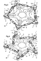
- a rotor 100 is shown with the support 3 and at least one branch 4 for attaching a mechanism 90 which is assigned to it.
- Each of the branches 4 that comprises the hub 3 is equipped at its free end with a pendular resonator 1 of the type shown in FIG. fig.2 , in particular to damp the harmonic vibrations to which the rotating rotor 100 is subjected.
- the mechanism 90 is equipped with damping means 8 of the pendulum movement of each mass 5. These damping means 8 take into account the characteristics of the carrier structure 106 in question, including its mass and excitation frequency. It is then a question of positively increasing the damping coefficients of the aerodynamic surfaces or those of the fuselage
- the rotor 100 is equipped with a vibration damping mechanism 90 which associates pendular resonators 1, comprising their mass 5 carried by the articulated arm 6 of movable mounting means of this mass 5 on the hub 3, with damping means 8 of the movements of the pendular resonators 1.
- damping means 8 are assigned to each of the pendular resonators 1 to counteract their effect as a function of the characteristics of the supporting structure, being interposed between the corresponding pendular resonator 1 and a gripping member 9 on the support 3 of the head 2.
- damping means 8 are capable of being of the type with mechanical or elastic deformation, as illustrated in FIGS. fig.3 and fig.4 or to be of the electromagnetic type employing cooperating magnetic members respectively assigned to the mass 5 and to the support 3, as illustrated in FIGS. fig.5 to fig.8 .
- the vibration damping mechanism 90 of the present invention is of reduced bulk and mass, and exploits existing members of the support 3 for the implantation of the damping means 8, pendular resonators 1 in particular and more particularly the arm articulated 6 and / or the mass 5 they comprise.
- the installation and adjustment of the damping means 8 may be performed optionally, or to be performed on an existing device according to the needs or instabilities of the carrier structure revealed in use. Such an installation can be carried out without major structural modification of the rotor 100 and / or the existing support structure, and the damping means 8 can be easily selected and set up according to the needs and / or according to the typology of the flying apparatus on which the mechanism or mechanisms must be implanted .
- the rotor head 2 is shown in the general plane of the support 3 which it comprises.
- This support 3 is provided with five branches 4 radially distributed, with which support 3 they form a one-piece assembly that can be obtained by molding.
- Pendular resonators 1 are installed at the free end of each of the branches 4 by means of the articulated arm 6 which they comprise. These arms 6 are articulated between their ends on the branch 4 which is assigned to them about a pivot axis A2 parallel to the axis of rotation A1 of the support 3.
- the mass 5 and the means of 8 damping assigned to them are mounted at a respective end of the corresponding articulated arm 6.
- the damping means 8 consist of hydraulic cylinders.
- the articulated arms 6 are advantageously arranged as lever arms, so that the effect provided by the pendulum mass 5 is amplified.
- Such amplification makes it possible to reduce the overall bulk and mass of the mechanism, in addition to an operation advantageously associated between two damping means 8 that can be assigned to neighboring resonators 1, as illustrated on FIG. fig.3 .
- the articulated arms 6 are T-shaped and the damping means 8 which are assigned to them are successively and respectively engaged on one of the wings of the T of the articulated arm 6 of a pendular resonator 1, and on one wings of the articulated arm 6 that includes a pendulum resonator 1 neighbor.
- an articulated arm 6 of a given pendular resonator 1 is therefore a gripping member 9 of a damping means 8 coming from a pendular resonator 1 adjacent said pendular resonator 1 given.
- a same damping means 8 is used for two adjacent pendular resonators 1, in cooperation with another damping means 8 successively connecting these pendular resonators 1 with a pendulum resonator 1 according to.
- the articulated arms 6 are arranged in lever arm being bent and articulated on the support 3 in their inflection zone.
- One end of the damping means 8 assigned to a pendular resonator 1 is articulated to the free end of the elbow of the corresponding articulated arm 6, and their other end is engaged on the support 3, and in particular on a branch 4 next to that carrying said pendular resonator 1.
- each arm 4 carrying a pendular resonator 1 gives a gripping member 9 of a damping means 8 from a pendular resonator 1 adjacent said pendular resonator 1 given.
- a rotor 100 is partially shown to illustrate an embodiment of a mechanism 90 of the invention.
- the support 3 carries a pendular resonator 1 whose arm 6 is articulated about a pivot axis A2 parallel to the axis A1 of rotation of the support 3.
- the damping means 8 are of the electromagnetic type and associate two cooperating magnetic members 10,11, one of which is arranged in a cage 10 inside which is disposed a body 11 forming the other magnetic member.
- the body 11 is formed of a magnetic mass and the cage 10 integrates an electromagnetic element 12, such as a coil in an open circuit or short-circuited with a resistor, providing a spontaneous damping of the pivoting movement of the articulated arm 6.
- the damping means 8 are carried by the branch 4 of the support 3 which is carrying the pendular resonator 1, being arranged axially offset relative to the general plane P of mobility of the resonator 1.
- the body 11 is connected to ground 5 of the pendular resonator 1 via a drive rod 13.
- An articulated arm pivotal movement 6 is braked by the body 11 which cooperates with the electromagnetic element 12 housed in the cage 10, and the vibrations to which the pendular resonator 1 is subjected are damped taking into account the characteristics of the bearing structure and / or imperfections found in the absorption of the vibrations obtained, from which the damping means 8 are adjusted.
- Each damping means 8, and more particularly the cage 10 is fixed by a dedicated member 10 'to a fixed gripping member 9, in this case a branch 4 of the support 3.
- the resonators pendulum 1 act according to the centrifugal force induced by the rotary movement of the rotor 100, their adjustment being obtained spontaneously according to the rotational speed of the rotor 100.
- the pendular resonators 1 dampen the vibrations induced by a forced excitation at a frequency corresponding to one or several harmonics of the rotor 100, on a narrow band of frequencies.
- the mechanism 90 associating the pendular resonators 1 and the damping means 8 which are assigned to them vibrates in quadrature of phase with respect to the carrying structure 106 and opposes its movement, a part of the damping Provided being transferred to the carrier structure 106.
- the damping provided by the damping means 8 against the movement of the pendular resonators 1 provides above all an increase in the band of vibration frequencies compared to that provided by the pendulum resonators 1 in themselves only and therefore respond to the need for vibrations at the origin of aeroelastic instabilities.
- a rotor 100 is equipped with a mechanism according to another embodiment of the present invention.
- the damping means 8 are of the electromagnetic type and are carried by the articulated arm 6 that includes the pendular resonator 1.
- the damping means 8 combine a cage 10 which incorporates a magnetic element 12 and which houses a magnetic body 11 coaxial.
- the body 11 is formed at least in part by the mass 5 that includes the pendular resonator 1, and is connected to a gripping member 9 secured to the support 3 by means of a rod 7 articulated at its periphery.
- a rotor 100 is equipped with a mechanism according to another embodiment of the present invention.
- the damping means 8 are of the electromagnetic type and combine a body 11 formed at least in part by the mass 5 that comprises the pendular resonator 1, which is housed inside a cage 10 carried by a gripping member 9 the hub 3 on which is articulated the resonator 1 by means of the articulated arm 6.
- the cage incorporates electromagnetic elements 14, such as tracks or a coil, which are arranged in axial offset with respect to the overall plane P of mobility of the resonator 1 being placed on either side of the body 11.
- These electromagnetic elements 14 are in particular shaped in angular sector, so that the mass 5 of the pendular resonator 1 is kept close to the electromagnetic elements 14 during its pivoting induced by the rotation of the rotor head 2.
Landscapes
- Engineering & Computer Science (AREA)
- Mechanical Engineering (AREA)
- Aviation & Aerospace Engineering (AREA)
- General Engineering & Computer Science (AREA)
- Physics & Mathematics (AREA)
- Acoustics & Sound (AREA)
- Vibration Prevention Devices (AREA)
- Fluid-Damping Devices (AREA)
- Turbine Rotor Nozzle Sealing (AREA)
- Support Of Aerials (AREA)
Abstract
Description
La présente invention est du domaine des équipements pour appareil volant comportant une structure porteuse liée à un rotor, tels qu'une hélice d'un avion ou un rotor d'un giravion et par exemple un hélicoptère. Plus particulièrement, la présente invention relève des mécanismes amortisseurs de vibrations induites par des instabilités aéroélastiques résultant d'un couplage entre les modes de vibrations de la structure porteuse et les modes de vibration du rotor. L'invention a pour objet un tel mécanisme et un appareil volant muni d'un tel mécanisme.The present invention is in the field of equipment for flying apparatus comprising a bearing structure connected to a rotor, such as a propeller of an aircraft or a rotor of a rotorcraft and for example a helicopter. More particularly, the present invention relates vibration damping mechanisms induced by aeroelastic instabilities resulting from a coupling between the vibration modes of the carrier structure and the vibration modes of the rotor. The invention relates to such a mechanism and a flying apparatus provided with such a mechanism.
Parmi les aéronefs, on distingue les appareils volants muni d'un rotor lié à une structure porteuse, par exemple un avion muni d'une hélice ou encore un giravion muni d'un rotor de sustentation voire de propulsion.Among the aircraft, there are flying apparatus provided with a rotor connected to a supporting structure, for example a plane equipped with a propeller or a rotorcraft equipped with a lift or propulsion rotor.
Le rotor comporte classiquement un mât rotor solidaire d'un moyeu, ce moyeu portant une pluralité de pales radialement réparties.The rotor conventionally comprises a rotor mast integral with a hub, this hub carrying a plurality of radially distributed blades.
Par ailleurs, la structure porteuse possède une cellule, dénommée parfois « fuselage » dans laquelle sont agencés des moyens moteurs aptes à entraîner en rotation le rotor. De plus, la structure porteuse comporte une structure de montage du rotor, permettant de fixer le rotor à la cellule.Furthermore, the carrier structure has a cell, sometimes called "fuselage" in which are arranged motor means adapted to drive the rotor in rotation. In addition, the carrier structure comprises a rotor mounting structure for attaching the rotor to the cell.
Une telle structure de montage comporte usuellement des moyens de transmission mécanique ainsi que des éléments de fixation de ces moyens de transmission à la cellule. Par exemple, une structure de montage d'un giravion, appelée « pylône » par l'homme du métier en langue française et « pylon » en langue anglaise, comprend une boîte de transmission principale de puissance et des éléments de fixations de cette boîte de transmission principale de puissance à la cellule, telles que des barres de suspension par exemple.Such a mounting structure usually comprises mechanical transmission means as well as fixing elements of these transmission means to the cell. For example, a mounting structure of a rotorcraft, called "pylon" by those skilled in the French language and "pylon" in the English language, includes a main power transmission gearbox and fastening elements of this box. main transmission of power to the cell, such as suspension bars for example.
Les moyens de motorisation de la structure porteuse entraînent alors le rotor via les moyens de transmission de la structure de montage.The motorization means of the carrier structure then drive the rotor via the transmission means of the mounting structure.
La structure porteuse et le rotor sont chacune soumises à des excitations forcées inhérentes à la vitesse d'avancement de l'aéronef.The carrier structure and the rotor are each subjected to forced excitation inherent to the speed of advance of the aircraft.
L'excitation dynamique du rotor, par exemple le rotor de sustentation et de propulsion d'un hélicoptère, résulte des charges aérodynamiques auxquelles ce rotor est soumis, ces charges aérodynamiques se décomposant en axes fixes en un effort coplanaire s'exerçant dans le plan général du moyeu du rotor qui est perpendiculaire à l'axe de rotation du rotor, en un effort axial qui s'exerce suivant l'axe de rotation du rotor, et en un moment coplanaire s'exerçant dans un plan perpendiculaire à l'axe de rotation du rotor tangentiellement au mouvement de rotation du moyeu du rotor. Les fréquences de telles vibrations en axes fixes c'est-à-dire liés à la cellule de la structure porteuse, sont égales au produit kbΩ où « Ω » désigne la vitesse de rotation du rotor, « b » le nombre de pales et « k » un nombre entier positif. Les fréquences fondamentales correspondent à un nombre « k » égal à l'unité. Ces excitations sont transmises du rotor à la structure par le pylône.The dynamic excitation of the rotor, for example the rotor of levitation and propulsion of a helicopter, results from aerodynamic loads to which this rotor is subjected, these aerodynamic loads decomposing into fixed axes in a coplanar effort exerted in the general plane of the hub of the rotor which is perpendicular to the axis of rotation of the rotor, in an axial force which is exerted along the axis of rotation of the rotor, and in a coplanar moment acting in a plane perpendicular to the axis of rotation of the rotor tangentially to the rotational movement of the rotor hub. The frequencies of such vibrations in fixed axes that is to say related to the cell of the carrier structure, are equal to the product kbΩ where "Ω" designates the speed of rotation of the rotor, "b" the number of blades and " k "a positive integer. The fundamental frequencies correspond to a number "k" equal to unity. These excitations are transmitted from the rotor to the structure by the pylon.
De même, la structure porteuse est soumise à des excitations forcées. Par exemple, la poutre de queue d'une cellule d'hélicoptère peut être excitée directement par un flux d'air turbulent provenant du rotor principal de sustentation et de propulsion.Similarly, the carrier structure is subjected to forced excitation. For example, the tail boom of a helicopter cell can be excited directly by a turbulent airflow from the main lift and propulsion rotor.
Les appareils volants munis d'un rotor sont globalement structurés pour pallier aux conséquences de telles vibrations.Flying devices equipped with a rotor are generally structured to mitigate the consequences of such vibrations.
A cet effet, il est courant d'équiper le rotor ou la structure de systèmes antivibratoires, dénommés parfois résonateur, pour filtrer les efforts dynamiques aux fréquences les plus gênantes, d'un point de vue confort des passagers ou encore pour éviter la casse d'un élément soumis à cette fatigue vibratoire. Ces systèmes antivibratoires sont alors réglés sur un des harmoniques de la vitesse de rotation du rotor.For this purpose, it is common to equip the rotor or the structure of antivibration systems, sometimes called resonator, to filter the dynamic forces at the most inconvenient frequencies, from a passenger comfort point of view or to avoid the breakage of passengers. an element subjected to this vibratory fatigue. These antivibration systems are then set to one of the harmonics of the rotational speed of the rotor.
Dans ces conditions, il a été proposé tel que selon le document
Cependant, de tels résonateurs pendulaires sont efficaces pour uniquement une fréquence donnée. De tels résonateurs pendulaires sont agencés pour équiper une tête de rotor implantée en sommet de la structure porteuse, le rotor procurant la sustentation voire la propulsion, et ne prennent pas en compte les caractéristiques propres de la structure porteuse relatives notamment à sa masse et à sa fréquence d'excitation.However, such pendular resonators are effective for only a given frequency. Such pendular resonators are arranged to equip a rotor head implanted at the top of the carrier structure, the rotor providing lift or propulsion, and do not take into account the specific characteristics of the bearing structure relating in particular to its mass and its excitation frequency.
En effet, les résonateurs ont pour effet d'étouffer les vibrations en créant une antirésonance à la fréquence donnée de réglage. En conséquence, le résonateur génère deux nouvelles résonances (ou modes de vibration) dont les deux fréquences respectives sont situées de part et d'autre de la fréquence d'antirésonance. La plage de fréquence définie par ces deux modes reste relativement étroite. Néanmoins, les deux modes de vibrations créés par les résonateurs ne sont normalement pas gênants dans la mesure où les deux résonances diffèrent de la fréquence donnée à traiter.Indeed, the resonators have the effect of stifling the vibrations by creating an antiresonance at the given frequency of adjustment. As a result, the resonator generates two new resonances (or modes of vibration) whose two respective frequencies are located on both sides of the antiresonance frequency. The frequency range defined by these two modes remains relatively narrow. Nevertheless, the two modes of vibration created by the resonators are not normally troublesome in that the two resonances differ from the given frequency to be processed.
Le document
On connait aussi des mécanismes amortisseurs de vibrations pour traiter les vibrations qui résultent de l'excitation forcé de la structure porteuse. On peut par exemple se reporter au document
Outre les excitations forcées, un autre phénomène vibratoire peut être à l'origine de problèmes majeurs.In addition to the forced excitations, another vibratory phenomenon can be at the origin of major problems.
Dans le domaine aéronautique en particulier, un problème réside dans l'atténuation des phénomènes vibratoires induits par les instabilités aéroélastiques que subit un appareil en vol. Par exemple, de telles instabilités aéroélastiques peuvent résulter du couplage entre les modes de vibration de la structure porteuse et le flux d'air en mouvement autour d'elle, à savoir notamment une structure de type voilure fixe (aile d'avion) ou voilure tournante (pales de rotor de giravion ou d'hélice d'avion). Il s'agit alors d'instabilités connues par l'homme du métier sous le terme général « flottement » ou « flutter » en langue anglaise.In the aeronautical field in particular, a problem lies in the attenuation of the vibration phenomena induced by the aeroelastic instabilities experienced by an aircraft in flight. For example, such aeroelastic instabilities may result from the coupling between the modes of vibration of the carrier structure and the flow of air moving around it, namely in particular a fixed wing type structure (wing of airplane) or wing rotating (rotorcraft rotor blades or airplane propeller blades). It is then instabilities known to the skilled person under the general term "floating" or "flutter" in the English language.
D'autres instabilités aéroélastiques correspondent par exemple aux instabilités dénommées « whirl flutter » en langue anglaise désignant le couplage des modes de vibrations d'un rotor équipé de pales ou d'aubes avec des modes de vibrations de la structure porteuse supportant le rotor.Other aeroelastic instabilities correspond for example to instabilities known as "whirl flutter" in English designating the coupling of the vibration modes of a rotor equipped with blades or blades with vibration modes of the supporting structure supporting the rotor.
Ces phénomènes de « flutter » et de « whirl flutter » se caractérisent par des vibrations à cycle limite ou des vibrations divergentes pouvant conduire à des ruptures de pièces mécaniques ou d'éléments structuraux. Il est donc impératif de prendre en compte ces phénomènes dans la conception de l'aéronef de façon à repousser les vitesses critiques (vitesse d'avancement, vitesse de rotation du rotor) au-delà des limites du domaine de vol.These phenomena of "flutter" and "whirl flutter" are characterized by limited-cycle vibrations or divergent vibrations that can lead to breaks in mechanical parts or structural elements. It is therefore imperative to take these phenomena into account in the design of the aircraft so as to push the critical speeds (forward speed, rotational speed of the rotor) beyond the limits of the flight envelope.
En particulier pour le « whirl-flutter », les constructeurs évitent que les modes du rotor soient susceptibles de se coupler aux modes de la structure porteuse, assurant ainsi la compatibilité de ces deux ensembles. Pour cela il suffit généralement de s'assurer du placement des fréquences propres et des amortissements respectifs des modes des différents ensembles.In particular for the whirl-flutter, the manufacturers avoid that the rotor modes are likely to couple with the modes of the carrier structure, thus ensuring the compatibility of these two sets. For this it is generally sufficient to ensure the placement of eigenfrequencies and respective damping modes of different sets.
Il est cependant difficile de modifier à posteriori les caractéristiques modales de la structure porteuse ou du rotor, si de tels phénomènes apparaissent au cours de la mise au point de l'aéronef. De plus, un constructeur peut être amené à modifier un aéronef existant pour répondre à des besoins spécifiques d'un utilisateur, ce qui peut impacter le comportement de l'appareil vis-à-vis de ces instabilités.However, it is difficult to modify a posteriori modal characteristics of the carrier structure or the rotor, if such phenomena occur during the development of the aircraft. In addition, a manufacturer may have to modify an existing aircraft to meet the specific needs of a user, which may impact the behavior of the aircraft vis-à-vis these instabilities.
Pour résoudre ces phénomènes qui peuvent apparaître comme explicité précédemment, le constructeur ne peut pas utiliser les résonateurs décris précédemment qui permettent de traiter des excitations forcées, et non pas des couplages. Dès lors, le constructeur choisit souvent de modifier sa structure porteuse, en la raidissant par exemple, une telle modification ayant un coût financier mais aussi un impact en terme de masse non négligeable. De plus, il peut être délicat de réaliser les modifications en question sur un appareil existant.To solve these phenomena that may appear as explained above, the manufacturer can not use the previously described resonators that can deal with forced excitation, and not couplings. Therefore, the manufacturer often chooses to modify its carrier structure, stiffening for example, such a modification having a financial cost but also an impact in terms of mass not insignificant. Moreover, he may be difficult to make the changes in question on an existing device.
La présente invention a alors pour objet de lutter contre le phénomène de couplage des modes de vibrations de la structure porteuse et du rotor d'un aéronef, par des moyens simples, peu onéreux, et pouvant être facilement implémentés sur un appareil existant. Le principe est d'apporter de l'amortissement au(x) mode(s) de vibration étant en cause dans le couplage instable.The present invention therefore aims to combat the phenomenon of coupling vibration modes of the carrier structure and the rotor of an aircraft, by simple means, inexpensive, and can be easily implemented on an existing device. The principle is to bring damping to the mode (s) of vibration being involved in the unstable coupling.
Selon l'invention, un mécanisme amortisseur de vibrations pour empêcher le couplage des modes de vibration d'une structure porteuse et des modes de vibration d'un rotor fixé à la structure comprend un support apte à être fixé à un rotor et au moins un résonateur comportant une masse portée par le support par l'intermédiaire de moyens de montage en mobilité de cette masse sur le support, ce mécanisme comportant des moyens d'amortissement du résonateur qui sont interposés entre le résonateur et un organe de prise sur le support.According to the invention, a vibration damping mechanism for preventing the coupling of the vibration modes of a carrier structure and the vibration modes of a rotor fixed to the structure comprises a support adapted to be fixed to a rotor and at least one resonator comprising a mass carried by the support by means of movable mounting means of this mass on the support, this mechanism comprising damping means of the resonator which are interposed between the resonator and a gripping member on the support.
Ainsi, le mécanisme est passif en comprenant un moyen de montage en mobilité passif et des moyens d'amortissement passifs. Ce mécanisme est réglé en fonction de la fréquence propre du mode propre de vibration de la structure porteuse à traiter.Thus, the mechanism is passive including passive mobility mounting means and passive damping means. This mechanism is adjusted according to the natural frequency of the eigenmode of vibration of the carrier structure to be treated.
Le mécanisme est donc auto-adaptatif et ne nécessite pas l'implantation de capteurs et d'un moyen de commande du déplacement de la masse.The mechanism is therefore self-adaptive and does not require the implantation of sensors and a means for controlling the movement of the mass.
On rappelle qu'un moyen d'amortissement apporte un effort en quadrature de phase avec le déplacement du corps considéré, ce qui a un effet de limitation en amplitude des oscillations. Un moyen générant des frictions a un tout autre effet, la friction empêchant un déplacement d'un corps par rapport à un autre corps jusqu'à un certain seuil d'effort. La friction n'est donc pas assimilable à de l'amortissement.It is recalled that a damping means provides a force in phase quadrature with the displacement of the body in question, which has a limiting effect in amplitude of the oscillations. A friction generating means has a completely different effect, the friction preventing a movement of a body relative to another body to a certain threshold of effort. Friction is therefore not comparable to damping.
La démarche de la présente invention a consisté dans sa globalité à rassembler sur un rotor non seulement un résonateur avec l'ensemble de ses composants propres, mais aussi des moyens d'amortissement liés au résonateur. Les moyens d'amortissement sont tarés en fonction des caractéristiques propres à la structure porteuse de l'appareil, et notamment en fonction de sa masse et de sa fréquence d'excitation. Le rotor est exploitée comme interface entre le résonateur et la structure porteuse pour l'interposition des moyens d'amortissement, et des organes propres au résonateur sont exploités au moins en partie pour l'implantation des moyens d'amortissement sur le rotor, avec pour avantage de réduire au mieux l'encombrement et la masse du mécanisme. L'ensemble du mécanisme est placé au plus proche de la source des vibrations harmoniques et/ ou d'instabilités aéroélastiques, avec pour avantage d'accroître ses performances. Le résonateur et les moyens d'amortissement constituent des organes structurellement distincts, les moyens d'amortissement pouvant être facilement implantés sur l'appareil indépendamment de l'implantation des résonateurs faite au préalable. L'implantation des moyens d'amortissement n'induit pas de modification de la structure porteuse en elle-même, et leur installation est potentiellement optionnelle selon les besoins.The approach of the present invention was in its entirety to gather on a rotor not only a resonator with all of its own components, but also damping means related to the resonator. The damping means are calibrated according to the characteristics of the carrier structure of the device, and in particular according to its mass and its excitation frequency. The rotor is used as an interface between the resonator and the carrier structure for the interposition of the damping means, and resonator-specific members are operated at least in part for the implementation of the damping means on the rotor, with advantage of reducing at best the size and mass of the mechanism. The entire mechanism is placed closer to the source of harmonic vibrations and / or aeroelastic instabilities, with the advantage of increasing its performance. The resonator and the damping means are structurally distinct members, the damping means can be easily implanted on the device regardless of the implantation of the resonators made beforehand. The implementation of damping means does not induce modification of the carrier structure itself, and their installation is potentially optional depending on the needs.
Le mécanisme a pour effet d'amortir les vibrations sur une plage de fréquence large, sans création d'antirésonance de vibrations contrairement à un résonateur pendulaire classique.The mechanism has the effect of damping vibrations over a wide frequency range, without creating vibration antiresonance unlike a conventional pendulum resonator.
L'amortissement apporté permet de modifier les modes de vibration de la structure porteuse supportant le rotor équipé du mécanisme, et empêche donc la création d'un couplage destructeur entre les modes de vibrations du rotor et de la structure porteuse de ce rotor.The damping provided makes it possible to modify the modes of vibration of the supporting structure supporting the rotor equipped with the mechanism, and thus prevents the creation of a destructive coupling between the vibration modes of the rotor and the bearing structure of this rotor.
De plus, on note que le mécanisme est cumulable avec un résonateur pendulaire traitant un des harmoniques du rotor.In addition, it is noted that the mechanism can be combined with a pendular resonator processing one of the harmonics of the rotor.
Les moyens de montage en mobilité comportant un bras articulé par masse, le résonateur est préférentiellement du type pendulaire et comprend une masse portée en pendule par le support du mécanisme par l'intermédiaire d'un bras articulé. Plus spécifiquement la masse est portée sur une branche ou organe analogue de ce support à laquelle il est affecté. Une telle branche est notamment un organe radialement étendu au-delà de l'axe de rotation du moyeu, dans un plan général qui est orthogonal à cet axe de rotation.The mobility mounting means comprising a mass-articulated arm, the resonator is preferably of the pendular type and comprises a mass carried pendulum by the support of the mechanism by means of an articulated arm. More specifically the mass is carried on a branch or similar member of the support to which it is assigned. Such a branch is in particular a member radially extended beyond the axis of rotation of the hub, in a general plane which is orthogonal to this axis of rotation.
L'agencement d'un tel bras articulé permet son exploitation aisée pour la prise des moyens d'amortissement sur les moyens de mobilité de la masse. Le bras articulé est non seulement un organe qui confère la mobilité pendulaire de la masse du résonateur, mais aussi est un organe par l'intermédiaire duquel les moyens d'amortissement du résonateur sont montés sur le support. L'organisation du mécanisme rend possible une exploitation aisée de moyens d'amortissement de types relativement quelconques, selon les besoins, le type d'appareil ou les caractéristiques propres à la structure porteuse devant être préservée des vibrations.The arrangement of such an articulated arm allows its easy operation for taking the damping means on the mobility means of the mass. The articulated arm is not only a member that confers the pendular mobility of the mass of the resonator, but also is an organ through which the damping means of the resonator are mounted on the support. The organization of the mechanism makes it possible to easily operate damping means of any type, depending on the needs, the type of apparatus or the characteristics specific to the supporting structure to be preserved from vibrations.
Le résonateur constitue plus particulièrement des moyens aptes à s'opposer aux vibrations sur une première plage de fréquences étroites induites par une excitation forcée à laquelle est soumis le rotor. Les moyens d'amortissement associés au résonateur sont aptes à s'opposer aux vibrations à l'origine d'instabilités sur une deuxième plage de fréquences plus large que ladite première plage de fréquences en étant adaptés en fonction des caractéristiques d'une structure porteuse de l'appareil volant et/ou en fonction d'imperfections constatées de l'amortissement des vibrations, et sont surtout aptes à s'opposer aux instabilités aéromécaniques (flottement...).The resonator is more particularly means able to oppose vibrations on a first narrow frequency range induced by a forced excitation to which the rotor is subjected. The damping means associated with the resonator are able to oppose vibrations causing instabilities over a second frequency range wider than said first frequency range by being adapted according to the characteristics of a carrier structure of the flying apparatus and / or as a function of observed imperfections of the vibration damping, and are especially able to oppose the aeromechanical instabilities (floating ...).
Selon divers modes de réalisation, l'organe de prise est indifféremment un organe fixe ou un organe mobile du support. Plus particulièrement, l'organe de prise que comporte le moyeu est susceptible d'être un organe fixe, tel qu'une dite branche ou organe analogue que comporte le support, ou d'être un organe mobile, tel qu'un résonateur, les moyens d'amortissement étant interposés en prise sur deux résonateurs voisins et plus particulièrement sur les bras articulés qu'ils comportent respectivement.According to various embodiments, the gripping member is indifferently a fixed member or a movable member of the support. More particularly, the engagement member that comprises the hub is likely to be a fixed member, such as a said branch or similar member that includes the support, or to be a movable member, such as a resonator, the damping means being interposed in engagement with two neighboring resonators and more particularly on the articulated arms which they respectively comprise.
En outre, la masse est portée en pendule sur le moyeu selon une mobilité de pivotement autour d'au moins un axe de pivotement. Un tel axe de pivotement est susceptible d'être orienté indifféremment parallèlement et/ou perpendiculairement à l'axe de rotation du moyeu. Par exemple encore, le bras des moyens de montage en mobilité de la masse est articulé sur le support selon une mobilité en pivotement autour d'un axe orienté parallèlement à l'axe de rotation de la tête de rotor pour amortir les vibrations forcées spécifiquement dans le plan général de la tête de rotor en générant un effort dans ce plan. Par exemple encore, ce bras est articulé sur le support selon une mobilité en pivotement autour d'un axe orienté orthogonalement à l'axe de rotation de la tête de rotor, pour atténuer voire amortir les vibrations forcées spécifiquement hors du plan général de la tête de rotor en générant un couple hors de ce plan.In addition, the mass is pendulum on the hub according to a pivotal mobility around at least one pivot axis. Such a pivot axis is capable of being oriented indifferently parallel and / or perpendicular to the axis of rotation of the hub. For example again, the arm of the mass movable mounting means is articulated on the support in a pivotal mobility about an axis oriented parallel to the axis of rotation of the rotor head to dampen the vibrations forced specifically in the general plane of the rotor head generating a force in this plane. For example again, this arm is articulated on the support in a mobility pivoting about an axis oriented orthogonal to the axis of rotation of the rotor head, to mitigate or even dampen the forced vibrations specifically out of the general plane of the head of rotor by generating a couple out of this plane.
Le bras articulé est avantageusement agencé en bras de levier, en comportant entre ses extrémités au moins une zone d'inflexion. Une telle zone d'inflexion est par exemple formée à partir d'un agencement du bras de levier en coude ou en T. Le bras articulé est articulé sur le moyeu entre ses extrémités et sur les moyens d'amortissement à l'une de ses extrémités, notamment à son extrémité la plus proche de l'axe de rotation du support. Le bras articulé est porteur de la masse à son autre extrémité de sorte que cette dernière soit disposée au plus éloigné de l'axe de rotation de la tête de rotor.The articulated arm is advantageously arranged as a lever arm, having between its ends at least one inflection zone. Such an inflection zone is for example formed from an arrangement of the lever arm elbow or T. The articulated arm is articulated on the hub between its ends and on the damping means to one of its ends, in particular at its end closest to the axis of rotation of the support. The articulated arm carries the mass at its other end so that the latter is disposed farthest from the axis of rotation of the rotor head.
Les moyens d'amortissement sont susceptibles d'être du type à déformation mécanique, tel qu'un vérin hydraulique, ou élastique à l'aide d'un organe formé à partir d'un élastomère à angle de perte important par exemple.The damping means are likely to be of the type with mechanical deformation, such as a hydraulic cylinder, or elastic with the aid of a member formed from a high loss angle elastomer for example.
Ainsi, les moyens d'amortissement peuvent être de type soit hydraulique, soit pneumatique, soit élastique ou soit magnétique, et n'incluent de fait pas des moyens mécaniques à frictions pour que des petits déplacements de la masse mobile soient permis.Thus, the damping means may be of either hydraulic, pneumatic, elastic or magnetic, and do not include in fact mechanical friction means for small displacements of the moving mass are allowed.
Les moyens d'amortissement ont favorablement un coefficient d'amortissement constant dans le temps, et constant en fonction de la température et de l'amplitude d'oscillation, pour produire un effort proportionnel à la vitesse de rotation de la masse.The damping means favorably have a constant damping coefficient over time, and constant as a function of the temperature and amplitude of oscillation, to produce a force proportional to the speed of rotation of the mass.
Un mécanisme à friction ne permettrait pas un fonctionnement correct car le déplacement de la masse ne serait autorisé qu'à partir d'un certain niveau d'effort. Pour de faibles excitations le système antivibratoire serait bloqué : le risque serait que la structure à isoler se caractérise par une réponse à cycle limite, le système antivibratoire ne remplissant sa fonction que pour les plus fortes amplitudes de vibration.A friction mechanism would not allow proper operation because the movement of the mass would be allowed only from a certain level of effort. For weak excitations the antivibration system would be blocked: the risk would be that the structure to be insulated is characterized by a limit cycle response, the antivibration system fulfilling its function only for the highest amplitudes of vibration.
Selon une variante, le résonateur est monté mobile sur une première branche du support. Les moyens d'amortissement sont interposés entre les moyens de montage en mobilité que comporte le résonateur, et une deuxième branche du moyeu voisine de la première branche qui constitue le dit organe de prise.According to one variant, the resonator is movably mounted on a first branch of the support. The damping means are interposed between the movable mounting means that includes the resonator, and a second branch of the hub adjacent to the first branch which constitutes said gripping member.
Selon une autre variante, une pluralité de résonateurs sont montés mobiles sur le support. Les moyens d'amortissement sont interposés entre les moyens de montage en mobilité de deux résonateurs voisins sur lesquels les moyens d'amortissement sont conjointement en prise.According to another variant, a plurality of resonators are movably mounted on the support. The damping means are interposed between the movable mounting means of two neighboring resonators on which the damping means are jointly engaged.
Les moyens d'amortissement sont encore susceptibles d'être du type électromagnétique associant des organes magnétiques coopérant respectivement affectés au résonateur et au support. Plus particulièrement, l'un des organes magnétiques est globalement agencé en cage intégrant au moins un élément magnétique, cette cage logeant un corps formant au moins en partie l'autre organe magnétique.The damping means are still likely to be of the electromagnetic type associating cooperating magnetic members respectively assigned to the resonator and the support. More particularly, one of the magnetic members is generally arranged in a cage incorporating at least one magnetic element, this cage housing a body forming at least partly the other magnetic member.
Selon une forme de réalisation, le résonateur est monté mobile en pivotement sur le support par l'intermédiaire d'un bras articulé autour d'un axe parallèle à l'axe de rotation du support.According to one embodiment, the resonator is pivotably mounted on the support by means of an arm articulated about an axis parallel to the axis of rotation of the support.
Selon une variante, la cage est portée par la branche du moyeu sur laquelle est monté le résonateur pendulaire, en étant disposée en décalage axial par rapport au plan global de mobilité du résonateur pendulaire. Le corps est relié au résonateur pendulaire par l'intermédiaire d'une bielle de manoeuvre.According to a variant, the cage is carried by the branch of the hub on which is mounted the pendulum resonator, being disposed in axial offset with respect to the overall plane of mobility of the pendular resonator. The body is connected to the pendulum resonator via an operating rod.
Selon une autre variante, la cage est portée par une branche du support sur laquelle est monté le résonateur pendulaire. Au moins un élément magnétique intégré à la cage est disposé en décalage axial par rapport au plan global de mobilité du résonateur et le corps constitue au moins en partie la masse du résonateur pendulaire.According to another variant, the cage is carried by a branch of the support on which is mounted the pendulum resonator. At least one magnetic element integrated in the cage is disposed axially offset relative to the overall mobility plane of the resonator and the body is at least partly the mass of the pendular resonator.
Selon encore une autre variante, la cage est portée par le bras d'articulation que comporte le résonateur pendulaire. Le corps constitue au moins en partie la masse du résonateur pendulaire et est tangentiellement articulé à l'extrémité d'une bielle de retenue qui est articulée à son autre extrémité sur l'organe de prise que comporte le support.According to yet another variant, the cage is carried by the hinge arm that includes the pendulum resonator. The body is at least partly the mass of the pendular resonator and is tangentially articulated to the end of a retaining rod which is articulated at its other end to the gripping member that comprises the support.
L'utilisation de moyens électromagnétiques, dont l'encombrement et la masse sont avantageusement réduits à partir de l'exploitation de la masse du résonateur pendulaire pour former l'un des organes magnétiques, permet d'éviter les frottements entre les pièces en mouvement.The use of electromagnetic means, whose bulk and mass are advantageously reduced from the exploitation of the mass of the pendulum resonator to form one magnetic members, avoids friction between moving parts.
Une application du mécanisme de la présente invention réside notamment dans son intégration à un rotor destiné à être implanté au sommet d'une structure porteuse notamment dans le cas d'une application à un giravion et en particulier un hélicoptère. Cependant, il doit être compris que le mécanisme de la présente invention est applicable à toute tête de rotor pour appareil volant.One application of the mechanism of the present invention resides notably in its integration with a rotor intended to be implanted at the top of a supporting structure, in particular in the case of an application to a rotorcraft and in particular a helicopter. However, it should be understood that the mechanism of the present invention is applicable to any rotor head for a flying apparatus.
Dans ce contexte, la présente invention a aussi pour objet un appareil volant muni d'un rotor et d'une structure porteuse comportant une cellule et une structure de montage du rotor à la cellule. Cet appareil volant est remarquable en ce que le rotor comporte un mécanisme amortisseur de vibrations selon l'invention tel que décrit précédemment pour empêcher le couplage des modes de vibration de la structure porteuse et des modes de vibration du rotor.In this context, the present invention also relates to a flying apparatus provided with a rotor and a bearing structure comprising a cell and a structure for mounting the rotor to the cell. This flying apparatus is remarkable in that the rotor comprises a vibration damping mechanism according to the invention as described above to prevent the coupling of the vibration modes of the carrier structure and vibration modes of the rotor.
Des exemples de réalisation de la présente invention vont être décrits en relation avec les figures des planches annexées, dans lesquelles :
- la
fig.1 illustre un aéronef selon l'invention. - la
fig.2 illustre une tête de rotor munie de résonateurs pendulaires qui sont articulés sur cette tête de rotor, et est composée de schémas a, b et c représentant respectivement diverses positions de masses pendulaires en mouvement que comprennent ces résonateurs. - les
fig.3 et fig.4 sont des illustrations d'une tête de rotor équipée d'un mécanisme de la présente invention selon des formes respectives de réalisation, vue dans un plan orthogonal à l'axe de rotation de cette tête de rotor. - la
fig.5 est une illustration partielle en coupe axiale d'une tête de rotor équipée d'un mécanisme de la présente invention selon une autre forme de réalisation. - la
fig.6 est une représentation schématique d'une tête de rotor équipée d'un mécanisme de la présente invention selon une autre forme de réalisation, vue dans un plan orthogonal à l'axe de rotation de cette tête de rotor. - les
fig.7 et fig.8 sont des représentations schématiques d'une tête de rotor équipée d'un mécanisme de la présente invention selon une autre forme de réalisation, respectivement vue dans un plan orthogonal et vue dans un plan parallèle à l'axe de rotation de cette tête de rotor.
- the
fig.1 illustrates an aircraft according to the invention. - the
fig.2 illustrates a rotor head provided with pendular resonators which are articulated on this rotor head, and is composed of diagrams a, b and c respectively representing various positions of oscillating masses in motion that include these resonators. - the
fig.3 and fig.4 are illustrations of a rotor head equipped with a mechanism of the present invention according to respective embodiments, seen in a plane orthogonal to the axis of rotation of the rotor head. - the
fig.5 is a partial illustration in axial section of a rotor head equipped with a mechanism of the present invention according to another embodiment. - the
fig.6 is a schematic representation of a rotor head equipped with a mechanism of the present invention according to another embodiment, seen in a plane orthogonal to the axis of rotation of this rotor head. - the
fig.7 and fig.8 are schematic representations of a rotor head equipped with a mechanism of the present invention according to another embodiment, respectively seen in an orthogonal plane and seen in a plane parallel to the axis of rotation of the rotor head.
En référence à la
La structure porteuse 106 possède une cellule 105 apte à accueillir des passagers et des moyens moteurs de type turbomoteur par exemple, ainsi qu'une structure de montage 104 incluant des moyens de transmission et portant le rotor 100. Les moyens de transmission sont en outre liés aux moyens de motorisation.The carrying
Par exemple, sur un hélicoptère, la structure de montage 104 comprend une boîte de transmission principale de puissance fixée sur la cellule 105 par des éléments de fixation, de type barre de suspension par exemple.For example, on a helicopter, the mounting
Le rotor 100 est alors pourvu d'un mât rotor 103 en prise d'une part sur la structure de montage 104 et d'autre part sur un moyeu 102 du rotor 100. Au moins deux pales 101 sont réparties radialement sur ce moyeu 102.The
Selon l'invention, un mécanisme 90 est agencé sur le rotor 100 pour éviter la création d'un couplage entre les modes de vibrations de la structure porteuse et les modes de vibrations du rotor. Ce mécanisme 90 comporte un support fixé au moyeu 102. Dès lors, le mécanisme 90 effectue une rotation autour d'un axe de rotation A1 du rotor.According to the invention, a
Sur la
Ces contraintes vibratoires dues aux vibrations harmoniques génèrent des vibrations qui induisent des efforts sur le rotor 100. Ces efforts sont orientés :
- *) axialement suivant l'axe de rotation A1 de la tête de rotor,
- *) dans le plan général P de la tête de rotor, et
- *) tangentiellement au trajet rotatif de la tête de rotor, en générant un couple.
- *) axially along the axis of rotation A1 of the rotor head,
- *) in the general plane P of the rotor head, and
- *) tangentially to the rotary path of the rotor head, generating a torque.
Les contraintes vibratoires dues à des phénomènes vibratoires divergents conduisent quant à elles à des instabilités aéroélastiques des structures. Pour contrer ces contraintes, la tête de rotor comprend un support 3 muni de branches 4 qui sont chacune porteuses d'un résonateur pendulaire 1. Chaque résonateur pendulaire 1 comprend une masse 5 portée en pendule au moyen d'un bras articulé 6 par une branche 4 qui lui est affectée. Sur l'exemple illustré, la masse 5 est articulée en pendule sur la branche 4 en mobilité.The vibratory stresses due to divergent vibratory phenomena lead to aeroelastic instabilities of the structures. To counter these constraints, the rotor head comprises a
Les résonateurs pendulaires 1 sont structurés et portés par le moyeu 3 pour amortir les vibrations auxquelles est soumis spécifiquement le rotor 100. Sur les schémas (a) et (b), les masses pendulaires 5 sont articulées sur le support 3 autour d'un axe de pivotement A2 orthogonal à l'axe de rotation A1, de sorte qu'elles soient mobiles par rapport au plan général P du support 3 en agissant hors de ce plan P. Sur le schéma (a), les masses pendulaires 5 génèrent un effort axial hors de ce plan P, et sur le schéma (b) les masses pendulaires 5 génèrent un moment hors du dit plan P. Sur le schéma (c), les masses pendulaires 5 sont articulées sur le support 3 autour d'axes respectifs de pivotement A2 qui sont parallèles à l'axe de rotation A1 du rotor 100, les masses pendulaires 5 générant un effort dans le plan général P du support 3.The
De tels résonateurs pendulaires 1 sont adaptés pour traiter des fréquences de vibrations au regard des harmoniques du rotor, mais ne prennent pas en compte les caractéristiques de la structure porteuse, à savoir le fuselage dans une application hélicoptère, relatives à sa masse et à sa fréquence d'excitation notamment. De tels résonateurs pendulaires ne sont pas adaptés au traitement des fréquences asynchrones du rotor. On rappelle qu'un apport d'un très faible amortissement par un moyen complémentaire pourrait éventuellement convenir.Such
Sur les
Plus particulièrement, le rotor 100 est équipé d'un mécanisme 90 amortisseur de vibrations qui associe des résonateurs pendulaires 1, comprenant leur masse 5 portée par le bras articulé 6 de moyens de montage en mobilité de cette masse 5 sur le moyeu 3, avec des moyens d'amortissement 8 des mouvements des résonateurs pendulaires 1.More particularly, the
Ces moyens d'amortissement 8 sont affectés à chacun des résonateurs pendulaires 1 pour contrer leur effet en fonction des caractéristiques propres à la structure porteuse, en étant interposés entre le résonateur pendulaire 1 correspondant et un organe de prise 9 sur le support 3 de la tête de rotor 2. De tels moyens d'amortissement 8 sont susceptibles d'être du type à déformation mécanique ou élastique, tels qu'illustrés sur les
Le mécanisme 90 amortisseur de vibrations de la présente invention est d'un encombrement et d'une masse réduits, et exploite des organes existants du support 3 pour l'implantation des moyens d'amortissement 8, résonateurs pendulaires 1 notamment et plus particulièrement le bras articulé 6 et/ou la masse 5 qu'ils comprennent. L'installation et le réglage des moyens d'amortissement 8 sont susceptibles d'être effectués optionnellement, voir d'être effectués sur un appareil existant en fonction des besoins ou d'instabilités de la structure porteuse révélées à l'usage. Une telle installation peut être effectuée sans modification structurelle majeure du rotor 100 et/ou de la structure porteuse existantes, et les moyens d'amortissement 8 peuvent être facilement sélectionnés et mis en place selon les besoins et/ou selon la typologie de l'appareil volant sur lequel le ou les mécanismes doivent être implantés.The
Sur les
Plus particulièrement selon la variante représentée sur la
Un même moyen d'amortissement 8 est exploité pour deux résonateurs pendulaires 1 voisins, en coopération avec un autre moyen d'amortissement 8 reliant successivement ces résonateurs pendulaires 1 avec un résonateur pendulaire 1 suivant.A same damping means 8 is used for two adjacent
Plus particulièrement encore selon la variante représentée sur la
Sur la
Chaque moyen d'amortissement 8, et plus particulièrement la cage 10, est fixé par un organe dédié 10' à un organe de prise 9 fixe, en l'occurrence une branche 4 du support 3.Each damping means 8, and more particularly the
Une distinction entre les résultats spécifiquement procurés par le résonateur 1 seulement et son association avec les moyens d'amortissement 8, réside dans une aptitude à amortir des vibrations de fréquences significativement différentes, respectivement relatives au rotor 100 et à la structure porteuse 106. Les résonateurs pendulaire 1 agissent selon la force centrifuge induite par le mouvement tournant du rotor 100, leur réglage étant obtenu spontanément en fonction du régime de rotation du rotor 100. Les résonateurs pendulaires 1 amortissent les vibrations induites par une excitation forcée suivant une fréquence correspondante à une ou plusieurs harmoniques de le rotor 100, sur une bande étroite de fréquences. Le mécanisme 90, de la présente invention associant les résonateurs pendulaires 1 et les moyens d'amortissement 8 qui leurs sont affectés vibre en quadrature de phase par rapport à la structure porteuse 106 et s'oppose à son mouvement, une partie de l'amortissement procuré étant transféré sur la structure porteuse 106. Par ailleurs, l'amortissement que procurent les moyens d'amortissement 8 à l'encontre du mouvement des résonateurs pendulaires 1 procure surtout un accroissement de la bande de fréquences des vibrations par rapport à celle que procure les résonateurs pendulaires 1 en eux-mêmes seulement et par conséquent répondent au besoin des vibrations à l'origine d'instabilités aéroélastiques.A distinction between the results specifically provided by the
Sur la
Sur les
Claims (17)
caractérisé en ce qu'il comprend un support (3) apte à être fixé audit rotor (100) et au moins un résonateur (1) comportant une masse (5) portée par ledit support (3) par l'intermédiaire de moyens de montage en mobilité (6) de cette masse (5) sur ledit support (3), ledit mécanisme (90) comportant des moyens d'amortissement (8) du résonateur (1) qui sont interposés entre le résonateur (1) et un organe de prise (9) sur ledit support (3).Vibration damping mechanism (90) for preventing the coupling of the vibration modes of a carrier structure (106) and the vibration modes of a rotor (100) attached to said carrier structure (106),
characterized in that it comprises a support (3) adapted to be fixed to said rotor (100) and at least one resonator (1) comprising a mass (5) carried by said support (3) by means of mounting means in mobility (6) of this mass (5) on said support (3), said mechanism (90) comprising damping means (8) of the resonator (1) which are interposed between the resonator (1) and a socket (9) on said support (3).
caractérisé en ce que, lesdits moyens de montage en mobilité comportant un bras articulé par masse, le résonateur (1) est du type pendulaire comprenant une masse (5) portée en pendule sur ledit support (3) par l'intermédiaire d'un bras articulé (6).Mechanism according to claim 1,
characterized in that , said movable mounting means having an arm articulated by mass, the resonator (1) is of the pendular type comprising a mass (5) carried in pendulum on said support (3) by means of an arm articulated (6).
caractérisé en ce que le résonateur (1) constitue des moyens aptes à s'opposer aux vibrations sur une première plage de fréquences étroites induites par une excitation forcée à laquelle est soumise le rotor (100), et en ce que les moyens d'amortissement (8) associés au résonateur (1) sont aptes à s'opposer aux vibrations à l'origine d'une instabilité sur une deuxième plage de fréquences plus large que ladite première plage en étant adaptés en fonction des caractéristiques d'une structure porteuse de l'appareil volant et/ou en fonction d'imperfections constatées de l'amortissement des vibrations.Mechanism according to any one of the preceding claims,
characterized in that the resonator (1) constitutes means capable of opposing the vibrations on a first range of narrow frequencies induced by a forced excitation to which the rotor (100) is subjected, and in that the damping means (8) associated with the resonator (1) are able to oppose vibrations causing instability on a second range of frequencies wider than said first range being adapted according to the characteristics of a structure carrying the flying apparatus and / or according to observed imperfections of the vibration damping.
caractérisé en ce que l'organe de prise (9) est indifféremment un organe fixe ou un organe mobile dudit mécanisme (90).Mechanism according to any one of the preceding claims,
characterized in that the gripping member (9) is indifferently a fixed member or a movable member of said mechanism (90).
caractérisé en ce que la masse (5) est portée en pendule selon une mobilité de pivotement autour d'au moins un axe de pivotement (A2) orienté indifféremment parallèlement et/ou perpendiculairement à un axe de rotation (A1) du support (3).Mechanism according to any one of the preceding claims,
characterized in that the mass (5) is carried in pendulum according to a pivotal mobility about at least one pivot axis (A2) oriented indifferently parallel and / or perpendicular to an axis of rotation (A1) of the support (3) .
caractérisé en ce que, lesdits moyens de montage en mobilité comportant un bras articulé par masse, chaque bras articulé (6) est agencé en bras de levier en étant articulé sur le support (3), en étant articulé sur les moyens d'amortissement (8) à l'une de ses extrémités et en étant porteur de la masse (5) à une autre extrémité.Mechanism according to any one of the preceding claims,
characterized in that , said movable mounting means having an arm articulated by mass, each articulated arm (6) is arranged as a lever arm being articulated on the support (3), being articulated on the damping means ( 8) at one of its ends and carrying the mass (5) at another end.
caractérisé en ce que les moyens d'amortissement (8) sont du type à déformation mécanique ou élastique.Mechanism according to any one of the preceding claims,
characterized in that the damping means (8) are of the type with mechanical or elastic deformation.
caractérisé en ce que le résonateur (1) est monté mobile sur une première branche (4) du support (3), et en ce que les moyens d'amortissement (8) sont interposés entre les moyens de montage en mobilité (6) que comporte le résonateur (1) et une deuxième branche (4) du moyeu (3) qui est voisine de la première branche (4) et qui constitue le dit organe de prise (9).Mechanism according to claim 7,
characterized in that the resonator (1) is movably mounted on a first limb (4) of the carrier (3), and in that the damping means (8) are interposed between the movable mounting means (6) that comprises the resonator (1) and a second leg (4) of the hub (3) which is close to the first leg (4) and which constitutes said gripping member (9).
caractérisé en ce qu'une pluralité de résonateurs (1) étant montés mobiles sur le support (3), les moyens d'amortissement (8) sont interposés entre les moyens de montage en mobilité (6) que comportent deux résonateurs (1) voisins et sur lesquels les moyens d'amortissement (8) sont conjointement en prise.Mechanism according to claim 7,
characterized in that a plurality of resonators (1) being movably mounted on the support (3), the damping means (8) are interposed between the movable mounting means (6) that comprise two resonators (1) neighbors and on which the damping means (8) are jointly engaged.
caractérisé en ce que les moyens d'amortissement (8) sont du type électromagnétique associant des organes magnétiques coopérants respectivement affectés au résonateur (1) et au support (3), l'un des organes magnétiques étant agencé en cage (10) intégrant au moins un élément magnétique (12,14), cette cage (10) logeant un corps (11) formant au moins en partie l'autre organe magnétique.Mechanism according to one of Claims 1 to 6,
characterized in that the damping means (8) are of the electromagnetic type associating cooperating magnetic members respectively assigned to the resonator (1) and to the support (3), one of the magnetic members being arranged in a cage (10) integrating with the least one magnetic element (12,14), this cage (10) housing a body (11) forming at least partly the other magnetic member.
caractérisé en ce que, lesdits moyens de montage en mobilité comportant un bras articulé par masse, le bras articulé (6) est monté mobile en pivotement sur le support (3) autour d'un axe de pivotement (A2) parallèle à l'axe de rotation (A1) du support (3).Mechanism according to claim 10,
characterized in that , said movable mounting means having a mass-articulated arm, the articulated arm (6) is pivotably mounted on the support (3) about a pivot axis (A2) parallel to the axis rotation (A1) of the support (3).
caractérisé en ce que la cage (10) est portée par une branche (4) du support (3) sur laquelle est monté le résonateur (1), la cage (10) étant disposée en décalage axial par rapport au plan global (P) de mobilité du résonateur pendulaire (1) et le corps (11) étant relié au résonateur (1) par l'intermédiaire d'une bielle de manoeuvre (13).Mechanism according to claim 11,
characterized in that the cage (10) is carried by a leg (4) of the support (3) on which the resonator (1) is mounted, the cage (10) being arranged axially offset with respect to the overall plane ( P ) of mobility of the pendular resonator (1) and the body (11) being connected to the resonator (1) via an operating rod (13).
caractérisé en ce que la cage (10) est portée par une branche (4) du support (3) sur laquelle est monté le résonateur (1), au moins un élément magnétique (14) intégré à la cage (10) étant disposé en décalage axial par rapport au plan global (P) de mobilité du résonateur (1) et le corps (11) constituant au moins en partie la masse (5) du résonateur (1).Mechanism according to claim 11,
characterized in that the cage (10) is carried by a branch (4) of the support (3) on which the resonator (1) is mounted, at least one magnetic element (14) integrated in the cage (10) being arranged in axial offset with respect to the overall plane ( P ) of mobility of the resonator (1) and the body (11) constituting at least part of the mass (5) of the resonator (1).
caractérisé en ce que la cage (10) est portée par le bras d'articulation (6) que comporte le résonateur (1), le corps (11) constituant au moins en partie la masse (5) du résonateur pendulaire (1) et étant tangentiellement articulé à l'extrémité d'une bielle de retenue (7) articulée à son autre extrémité sur l'organe de prise (9) que comporte le support (3).Mechanism according to claim 11,
characterized in that the cage (10) is carried by the hinge arm (6) which the resonator (1) comprises, the body (11) constituting at least part of the mass (5) of the pendulum resonator (1) and being tangentially articulated at the end of a retaining rod (7) articulated at its other end to the gripping member (9) that comprises the support (3).
caractérisé en ce que ledit mécanisme est passif.Mechanism according to any one of the preceding claims,
characterized in that said mechanism is passive.
caractérisé en ce que les moyens d'amortissement (8) sont de type soit hydraulique, soit pneumatique, soit élastique ou soit magnétique.Mechanism according to any one of the preceding claims,
characterized in that the damping means (8) are of either hydraulic, pneumatic, elastic or magnetic type.
caractérisé en ce que ledit rotor (100) comporte un mécanisme (90) amortisseur de vibrations selon l'une quelconque des revendications précédentes pour empêcher le couplage des modes de vibration de ladite structure porteuse (106) et des modes de vibration dudit rotor (100).A flying apparatus (110) having a rotor (100) and a carrier (106) having a cell (105) and a mounting structure (104) of the rotor (100) to said cell (105),
characterized in that said rotor (100) comprises a vibration damping mechanism (90) according to any one of the preceding claims for preventing coupling of the vibration modes of said carrier structure (106) and vibration modes of said rotor (100). ).
Applications Claiming Priority (1)
| Application Number | Priority Date | Filing Date | Title |
|---|---|---|---|
| FR0906121A FR2954274B1 (en) | 2009-12-17 | 2009-12-17 | VIBRATION DAMPER MECHANISM, AND FLYING APPARATUS PROVIDED WITH A CARRIER STRUCTURE AND A ROTOR HAVING SUCH A MECHANISM |
Publications (2)
| Publication Number | Publication Date |
|---|---|
| EP2340997A1 true EP2340997A1 (en) | 2011-07-06 |
| EP2340997B1 EP2340997B1 (en) | 2012-05-09 |
Family
ID=42320865
Family Applications (1)
| Application Number | Title | Priority Date | Filing Date |
|---|---|---|---|
| EP10015170A Active EP2340997B1 (en) | 2009-12-17 | 2010-12-01 | Vibration damping mechanism and aircraft with a support structure and a rotor with such a mechanism |
Country Status (6)
| Country | Link |
|---|---|
| US (1) | US8695917B2 (en) |
| EP (1) | EP2340997B1 (en) |
| KR (1) | KR101234831B1 (en) |
| CN (1) | CN102102733B (en) |
| AT (1) | ATE556927T1 (en) |
| FR (1) | FR2954274B1 (en) |
Families Citing this family (27)
| Publication number | Priority date | Publication date | Assignee | Title |
|---|---|---|---|---|
| JP5022457B2 (en) * | 2010-02-17 | 2012-09-12 | 三菱重工業株式会社 | Vibration reducing apparatus and vibration reducing method |
| GB2482545B (en) * | 2010-08-06 | 2017-05-03 | Ge Aviat Systems Ltd | Aircraft propellers with composite blades mounted to a single propeller hub |
| EP2670661B1 (en) * | 2011-02-04 | 2015-01-14 | Lord Corporation | Rotary wing aircraft vibration control system with resonant inertial actuators |
| US9126680B2 (en) * | 2011-11-16 | 2015-09-08 | Textron Innovations Inc. | Dual mode rotor hub assembly |
| US9260185B2 (en) * | 2012-01-25 | 2016-02-16 | Textron Innovations Inc. | System and method of harvesting power with a rotor hub damper |
| JP5863528B2 (en) * | 2012-03-23 | 2016-02-16 | 三菱重工業株式会社 | Vibration reduction device |
| KR102241339B1 (en) * | 2014-01-15 | 2021-04-15 | 로오드 코포레이션 | Hub-based active vibration control systems, devices, and methods with offset imbalanced rotors |
| US10065730B2 (en) * | 2014-01-22 | 2018-09-04 | Bell Helicopter Textron Inc. | Active vibration control system with non-concentric revolving masses |
| FR3019522B1 (en) * | 2014-04-07 | 2016-05-20 | Airbus Helicopters | REMOVABLE SUSTAINABLE ASSEMBLY OF A GIRAVION AND GIRAVION |
| WO2016053464A1 (en) * | 2014-10-03 | 2016-04-07 | Sikorsky Aircraft Corporation | Blade damper with a magnetic contaminants trap |
| US9788446B1 (en) * | 2015-03-27 | 2017-10-10 | Paul H. Townsend | Mobile vibration isolation device |
| US9399380B1 (en) * | 2015-04-17 | 2016-07-26 | Ping Fan | Vibration-type electric generator applied to automobile suspension system |
| US9828084B2 (en) * | 2015-05-06 | 2017-11-28 | The Boeing Company | Vibration dampening for horizontal stabilizers |
| US10507920B2 (en) * | 2015-05-18 | 2019-12-17 | Sikorsky Aircraft Corp. | Systems and methods for lifting body vibration control |
| CN106741926A (en) * | 2015-11-24 | 2017-05-31 | 中国直升机设计研究所 | A kind of helicopter ball flexible hub damper arrangement form |
| CN205186541U (en) * | 2015-11-24 | 2016-04-27 | 零度智控(北京)智能科技有限公司 | Unmanned aerial vehicle organism support |
| US10457388B2 (en) * | 2016-02-16 | 2019-10-29 | Bell Helicopter Textron, Inc. | Rotor assembly with high lock-number blades |
| US10472057B2 (en) * | 2016-02-16 | 2019-11-12 | Bell Helicopter Textron Inc. | Rotor assembly with high lock-number blades |
| FR3052209B1 (en) * | 2016-06-02 | 2018-06-01 | Airbus Helicopters | RESONATOR, AND AIRCRAFT PROVIDED WITH THIS RESONATOR |
| FR3053312B1 (en) * | 2016-06-29 | 2019-07-19 | Airbus Helicopters | ROTOR AND AIRCRAFT PROVIDED WITH SUCH A ROTOR |
| US10773798B2 (en) * | 2017-09-29 | 2020-09-15 | Bell Textron Inc. | Rotor hub with blade-to-blade dampers attached to the pitch change axis |
| US10746047B2 (en) | 2017-10-27 | 2020-08-18 | General Electric Company | Structure for mitigating vibratory modes of counter-rotating engine rotors |
| US10597150B2 (en) * | 2018-04-24 | 2020-03-24 | Textron Innovations Inc. | Articulated rotor systems with blade-to-blade damping |
| EP3755623A1 (en) * | 2018-05-08 | 2020-12-30 | AVX Aircraft Company | Rotor hub |
| US20220144416A1 (en) * | 2020-11-08 | 2022-05-12 | Bell Textron Inc. | Liquid inertia vibration elimination system with compound period strut |
| US11428160B2 (en) | 2020-12-31 | 2022-08-30 | General Electric Company | Gas turbine engine with interdigitated turbine and gear assembly |
| CN113353251B (en) * | 2021-08-09 | 2021-12-28 | 四川聚变未来航空科技有限公司 | Multi-rotor aircraft |
Citations (3)
| Publication number | Priority date | Publication date | Assignee | Title |
|---|---|---|---|---|
| US5934424A (en) | 1996-11-01 | 1999-08-10 | The University Of Connecticut | Centrifugal delayed resonator pendulum absorber |
| FR2784350A1 (en) | 1998-10-12 | 2000-04-14 | Eurocopter France | Helicopter tail shake vibration compensator has control operating drive to move weight compensating for induced vibration |
| FR2808256A1 (en) | 2000-04-27 | 2001-11-02 | Eurocopter France | Helicopter main rotor with anti-vibration head includes two pendulums connected to support rotating with hub, pendulum oscillates on hub between two neighboring rotor blades |
Family Cites Families (13)
| Publication number | Priority date | Publication date | Assignee | Title |
|---|---|---|---|---|
| US3484173A (en) * | 1968-12-06 | 1969-12-16 | United Aircraft Corp | Double action damper bumper |
| FR2630703B1 (en) * | 1988-04-29 | 1990-08-24 | Aerospatiale | ROTOR HEAD OF A GIRAVION WITH ELASTIC RETURN INTERPAL DRAWERS WITH BUILT-IN DAMPING |
| FR2653405B1 (en) * | 1989-10-20 | 1992-02-07 | Aerospatiale | ROTARY VISCO-ELASTIC DEVICE FOR ELASTIC RECALLING AND DAMPING IN TRAIL FOR A ROTOR BLADE OF A GIRAVION, AND ROTOR HEAD COMPRISING SAME. |
| US5431261A (en) * | 1994-05-12 | 1995-07-11 | University Of Connecticut | Delayed resonators as active dynamic absorbers |
| FR2733961B1 (en) * | 1995-05-12 | 1997-07-18 | Eurocopter France | DEVICE FOR DAMPING THE BLADES OF A ROTOR |
| FR2750948B1 (en) * | 1996-07-12 | 1998-10-30 | Eurocopter France | DEVICE FOR LOCKING, AT LEAST IN STEP, THE BLADES OF A ROTOR |
| FR2768995B1 (en) * | 1997-10-01 | 1999-12-03 | Eurocopter France | PENDULUM ROTOR HEAD RESONATOR |
| FR2826933B1 (en) * | 2001-07-04 | 2003-09-26 | Eurocopter France | FLUID INERTIA TRAIL SHOCK ABSORBER FOR A GIRAVION ROTOR |
| FR2835506B1 (en) * | 2002-02-06 | 2004-03-12 | Eurocopter France | DOUBLE PISTON TRAIN SHOCK ABSORBER FOR ROTOR OF ROTOR |
| FR2837462B1 (en) * | 2002-03-20 | 2004-05-28 | Eurocopter France | ROTOR OF GIRAVION WITH HOMOCINETIC DRIVE |
| FR2890937B1 (en) * | 2005-09-21 | 2009-04-24 | Eurocopter France | ROTOR OF GIRAVION WITH ARTICULATED BLADES IN BEAT AND IN TRAINEE |
| FR2910877B1 (en) * | 2006-12-28 | 2009-09-25 | Eurocopter France | IMPROVEMENT TO ROTORS OF GIRAVIONS EQUIPPED WITH INTERPAL SHOCK ABSORBERS |
| PL2184229T3 (en) * | 2008-11-11 | 2013-04-30 | Agustawestland Spa | Helicopter rotor |
-
2009
- 2009-12-17 FR FR0906121A patent/FR2954274B1/en active Active
-
2010
- 2010-12-01 AT AT10015170T patent/ATE556927T1/en active
- 2010-12-01 EP EP10015170A patent/EP2340997B1/en active Active
- 2010-12-15 US US12/968,653 patent/US8695917B2/en active Active
- 2010-12-15 KR KR1020100128436A patent/KR101234831B1/en active IP Right Grant
- 2010-12-15 CN CN201010604120.4A patent/CN102102733B/en active Active
Patent Citations (3)
| Publication number | Priority date | Publication date | Assignee | Title |
|---|---|---|---|---|
| US5934424A (en) | 1996-11-01 | 1999-08-10 | The University Of Connecticut | Centrifugal delayed resonator pendulum absorber |
| FR2784350A1 (en) | 1998-10-12 | 2000-04-14 | Eurocopter France | Helicopter tail shake vibration compensator has control operating drive to move weight compensating for induced vibration |
| FR2808256A1 (en) | 2000-04-27 | 2001-11-02 | Eurocopter France | Helicopter main rotor with anti-vibration head includes two pendulums connected to support rotating with hub, pendulum oscillates on hub between two neighboring rotor blades |
Also Published As
| Publication number | Publication date |
|---|---|
| EP2340997B1 (en) | 2012-05-09 |
| ATE556927T1 (en) | 2012-05-15 |
| FR2954274A1 (en) | 2011-06-24 |
| KR101234831B1 (en) | 2013-02-19 |
| US8695917B2 (en) | 2014-04-15 |
| US20110155841A1 (en) | 2011-06-30 |
| KR20110069721A (en) | 2011-06-23 |
| CN102102733A (en) | 2011-06-22 |
| CN102102733B (en) | 2013-08-21 |
| FR2954274B1 (en) | 2012-02-24 |
Similar Documents
| Publication | Publication Date | Title |
|---|---|---|
| EP2340997B1 (en) | Vibration damping mechanism and aircraft with a support structure and a rotor with such a mechanism | |
| EP2356027B1 (en) | System for joining two components like an aircraft engine and an aircraft pylon | |
| EP2336024B1 (en) | Rotor bearing structure, rotorcraft carrying said bearing structure and method for avoiding instable coupling of the system eigenmodes | |
| FR2638418A1 (en) | DEVICE FOR ASSEMBLING THE FINES OF A PROPELLER | |
| EP1939087B1 (en) | Rotorcraft rotor improvement equipped with inter-blade shock absorbers | |
| EP1553324A1 (en) | Bearing support with double stiffness | |
| EP2754612B1 (en) | Three-point shackle with vibration-filtering capacity and aircraft engine attachment provided with such a shackle | |
| EP2253535B1 (en) | Device with distributed masses for reducing the vibration caused by a lift rotor of a rotorcraft, and hub of a rotor provided with such a device | |
| JP5544123B2 (en) | Helicopter rotor | |
| FR2982584A1 (en) | DEVICE FOR NOT VARYING THE BLADES OF A SUSTENTATION ROTOR | |
| CA2914331C (en) | Rear rotorcraft rotor, rotorcraft equipped with such a rear rotor and static and/or dynamic balancing method for a rear rotor of a rotorcraft | |
| EP3252339B1 (en) | A resonator, and an aircraft fitted with the resonator | |
| EP2138399A1 (en) | Blade for reducing the drag movements of said blade and method for reducing such a drag movement | |
| EP0742144A1 (en) | Device for damping lead-lag motion of rotor blades of a helicopter | |
| FR2982583A1 (en) | MEANS FOR ANTI-VIBRATION SUSPENSION OF AN AIRCRAFT POWER TRANSMISSION BOX, ANTI-VIBRATION SUSPENSION DEVICE, AND AN AIRCRAFT | |
| FR3017566A1 (en) | AIRCRAFT AND AIRCRAFT ENGINE INSTALLATION HAVING A LINK DEVICE FOR BINDING A POWER TRANSMISSION BOX AND A MOTOR | |
| FR2974347A1 (en) | ROTOR DAMPING DEVICE, ROTOR AND AIRCRAFT ASSOCIATED | |
| WO2014174222A1 (en) | Structure for suspending a twin prop-fan engine from a structural element of an aircraft | |
| KR101227106B1 (en) | A blade damper, and a rotor fitted with such a damper | |
| EP3976928B1 (en) | Assembly for turbomachine and turbomachine | |
| WO2022157443A1 (en) | Assembly comprising an aircraft turbine engine and mounting pylon thereof | |
| EP2853490B1 (en) | Dampening device for a supercritical transmission shaft | |
| CA2876809C (en) | Shock absorbing device for a supercritical drive shaft | |
| BE488057A (en) |
Legal Events
| Date | Code | Title | Description |
|---|---|---|---|
| PUAI | Public reference made under article 153(3) epc to a published international application that has entered the european phase |
Free format text: ORIGINAL CODE: 0009012 |
|
| AK | Designated contracting states |
Kind code of ref document: A1 Designated state(s): AL AT BE BG CH CY CZ DE DK EE ES FI FR GB GR HR HU IE IS IT LI LT LU LV MC MK MT NL NO PL PT RO RS SE SI SK SM TR |
|
| AX | Request for extension of the european patent |
Extension state: BA ME |
|
| 17P | Request for examination filed |
Effective date: 20110616 |
|
| RIN1 | Information on inventor provided before grant (corrected) |
Inventor name: CRANGA, PAUL Inventor name: MANFREDOTTI, THOMAS Inventor name: RE, JOACHIM Inventor name: PULA, MATTHIEU |
|
| 17Q | First examination report despatched |
Effective date: 20110929 |
|
| GRAP | Despatch of communication of intention to grant a patent |
Free format text: ORIGINAL CODE: EPIDOSNIGR1 |
|
| GRAS | Grant fee paid |
Free format text: ORIGINAL CODE: EPIDOSNIGR3 |
|
| GRAA | (expected) grant |
Free format text: ORIGINAL CODE: 0009210 |
|
| AK | Designated contracting states |
Kind code of ref document: B1 Designated state(s): AL AT BE BG CH CY CZ DE DK EE ES FI FR GB GR HR HU IE IS IT LI LT LU LV MC MK MT NL NO PL PT RO RS SE SI SK SM TR |
|
| REG | Reference to a national code |
Ref country code: GB Ref legal event code: FG4D Free format text: NOT ENGLISH |
|
| REG | Reference to a national code |
Ref country code: AT Ref legal event code: REF Ref document number: 556927 Country of ref document: AT Kind code of ref document: T Effective date: 20120515 Ref country code: CH Ref legal event code: EP |
|
| REG | Reference to a national code |
Ref country code: IE Ref legal event code: FG4D Free format text: LANGUAGE OF EP DOCUMENT: FRENCH |
|
| REG | Reference to a national code |
Ref country code: DE Ref legal event code: R096 Ref document number: 602010001302 Country of ref document: DE Effective date: 20120712 |
|
| REG | Reference to a national code |
Ref country code: NL Ref legal event code: VDEP Effective date: 20120509 |
|
| REG | Reference to a national code |
Ref country code: LT Ref legal event code: MG4D Effective date: 20120509 |
|
| PG25 | Lapsed in a contracting state [announced via postgrant information from national office to epo] |
Ref country code: SE Free format text: LAPSE BECAUSE OF FAILURE TO SUBMIT A TRANSLATION OF THE DESCRIPTION OR TO PAY THE FEE WITHIN THE PRESCRIBED TIME-LIMIT Effective date: 20120509 Ref country code: FI Free format text: LAPSE BECAUSE OF FAILURE TO SUBMIT A TRANSLATION OF THE DESCRIPTION OR TO PAY THE FEE WITHIN THE PRESCRIBED TIME-LIMIT Effective date: 20120509 Ref country code: PL Free format text: LAPSE BECAUSE OF FAILURE TO SUBMIT A TRANSLATION OF THE DESCRIPTION OR TO PAY THE FEE WITHIN THE PRESCRIBED TIME-LIMIT Effective date: 20120509 Ref country code: NO Free format text: LAPSE BECAUSE OF FAILURE TO SUBMIT A TRANSLATION OF THE DESCRIPTION OR TO PAY THE FEE WITHIN THE PRESCRIBED TIME-LIMIT Effective date: 20120809 Ref country code: IS Free format text: LAPSE BECAUSE OF FAILURE TO SUBMIT A TRANSLATION OF THE DESCRIPTION OR TO PAY THE FEE WITHIN THE PRESCRIBED TIME-LIMIT Effective date: 20120909 Ref country code: CY Free format text: LAPSE BECAUSE OF FAILURE TO SUBMIT A TRANSLATION OF THE DESCRIPTION OR TO PAY THE FEE WITHIN THE PRESCRIBED TIME-LIMIT Effective date: 20120509 Ref country code: LT Free format text: LAPSE BECAUSE OF FAILURE TO SUBMIT A TRANSLATION OF THE DESCRIPTION OR TO PAY THE FEE WITHIN THE PRESCRIBED TIME-LIMIT Effective date: 20120509 Ref country code: RS Free format text: LAPSE BECAUSE OF FAILURE TO SUBMIT A TRANSLATION OF THE DESCRIPTION OR TO PAY THE FEE WITHIN THE PRESCRIBED TIME-LIMIT Effective date: 20120509 |
|
| REG | Reference to a national code |
Ref country code: AT Ref legal event code: MK05 Ref document number: 556927 Country of ref document: AT Kind code of ref document: T Effective date: 20120509 |
|
| PG25 | Lapsed in a contracting state [announced via postgrant information from national office to epo] |
Ref country code: HR Free format text: LAPSE BECAUSE OF FAILURE TO SUBMIT A TRANSLATION OF THE DESCRIPTION OR TO PAY THE FEE WITHIN THE PRESCRIBED TIME-LIMIT Effective date: 20120509 Ref country code: SI Free format text: LAPSE BECAUSE OF FAILURE TO SUBMIT A TRANSLATION OF THE DESCRIPTION OR TO PAY THE FEE WITHIN THE PRESCRIBED TIME-LIMIT Effective date: 20120509 Ref country code: PT Free format text: LAPSE BECAUSE OF FAILURE TO SUBMIT A TRANSLATION OF THE DESCRIPTION OR TO PAY THE FEE WITHIN THE PRESCRIBED TIME-LIMIT Effective date: 20120910 Ref country code: LV Free format text: LAPSE BECAUSE OF FAILURE TO SUBMIT A TRANSLATION OF THE DESCRIPTION OR TO PAY THE FEE WITHIN THE PRESCRIBED TIME-LIMIT Effective date: 20120509 Ref country code: GR Free format text: LAPSE BECAUSE OF FAILURE TO SUBMIT A TRANSLATION OF THE DESCRIPTION OR TO PAY THE FEE WITHIN THE PRESCRIBED TIME-LIMIT Effective date: 20120810 |
|
| PG25 | Lapsed in a contracting state [announced via postgrant information from national office to epo] |
Ref country code: AT Free format text: LAPSE BECAUSE OF FAILURE TO SUBMIT A TRANSLATION OF THE DESCRIPTION OR TO PAY THE FEE WITHIN THE PRESCRIBED TIME-LIMIT Effective date: 20120509 Ref country code: NL Free format text: LAPSE BECAUSE OF FAILURE TO SUBMIT A TRANSLATION OF THE DESCRIPTION OR TO PAY THE FEE WITHIN THE PRESCRIBED TIME-LIMIT Effective date: 20120509 Ref country code: SK Free format text: LAPSE BECAUSE OF FAILURE TO SUBMIT A TRANSLATION OF THE DESCRIPTION OR TO PAY THE FEE WITHIN THE PRESCRIBED TIME-LIMIT Effective date: 20120509 Ref country code: EE Free format text: LAPSE BECAUSE OF FAILURE TO SUBMIT A TRANSLATION OF THE DESCRIPTION OR TO PAY THE FEE WITHIN THE PRESCRIBED TIME-LIMIT Effective date: 20120509 Ref country code: CZ Free format text: LAPSE BECAUSE OF FAILURE TO SUBMIT A TRANSLATION OF THE DESCRIPTION OR TO PAY THE FEE WITHIN THE PRESCRIBED TIME-LIMIT Effective date: 20120509 Ref country code: DK Free format text: LAPSE BECAUSE OF FAILURE TO SUBMIT A TRANSLATION OF THE DESCRIPTION OR TO PAY THE FEE WITHIN THE PRESCRIBED TIME-LIMIT Effective date: 20120509 Ref country code: RO Free format text: LAPSE BECAUSE OF FAILURE TO SUBMIT A TRANSLATION OF THE DESCRIPTION OR TO PAY THE FEE WITHIN THE PRESCRIBED TIME-LIMIT Effective date: 20120509 |
|
| PLBE | No opposition filed within time limit |
Free format text: ORIGINAL CODE: 0009261 |
|
| STAA | Information on the status of an ep patent application or granted ep patent |
Free format text: STATUS: NO OPPOSITION FILED WITHIN TIME LIMIT |
|
| 26N | No opposition filed |
Effective date: 20130212 |
|
| REG | Reference to a national code |
Ref country code: DE Ref legal event code: R097 Ref document number: 602010001302 Country of ref document: DE Effective date: 20130212 |
|
| BERE | Be: lapsed |
Owner name: EUROCOPTER Effective date: 20121231 |
|
| PG25 | Lapsed in a contracting state [announced via postgrant information from national office to epo] |
Ref country code: MC Free format text: LAPSE BECAUSE OF NON-PAYMENT OF DUE FEES Effective date: 20121231 Ref country code: BG Free format text: LAPSE BECAUSE OF FAILURE TO SUBMIT A TRANSLATION OF THE DESCRIPTION OR TO PAY THE FEE WITHIN THE PRESCRIBED TIME-LIMIT Effective date: 20120809 |
|
| REG | Reference to a national code |
Ref country code: IE Ref legal event code: MM4A |
|
| PG25 | Lapsed in a contracting state [announced via postgrant information from national office to epo] |
Ref country code: BE Free format text: LAPSE BECAUSE OF NON-PAYMENT OF DUE FEES Effective date: 20121231 |
|
| REG | Reference to a national code |
Ref country code: DE Ref legal event code: R119 Ref document number: 602010001302 Country of ref document: DE Effective date: 20130702 |
|
| PG25 | Lapsed in a contracting state [announced via postgrant information from national office to epo] |
Ref country code: IE Free format text: LAPSE BECAUSE OF NON-PAYMENT OF DUE FEES Effective date: 20121201 Ref country code: ES Free format text: LAPSE BECAUSE OF FAILURE TO SUBMIT A TRANSLATION OF THE DESCRIPTION OR TO PAY THE FEE WITHIN THE PRESCRIBED TIME-LIMIT Effective date: 20120820 Ref country code: DE Free format text: LAPSE BECAUSE OF NON-PAYMENT OF DUE FEES Effective date: 20130702 |
|
| PG25 | Lapsed in a contracting state [announced via postgrant information from national office to epo] |
Ref country code: AL Free format text: LAPSE BECAUSE OF FAILURE TO SUBMIT A TRANSLATION OF THE DESCRIPTION OR TO PAY THE FEE WITHIN THE PRESCRIBED TIME-LIMIT Effective date: 20120509 Ref country code: MT Free format text: LAPSE BECAUSE OF FAILURE TO SUBMIT A TRANSLATION OF THE DESCRIPTION OR TO PAY THE FEE WITHIN THE PRESCRIBED TIME-LIMIT Effective date: 20120509 |
|
| PG25 | Lapsed in a contracting state [announced via postgrant information from national office to epo] |
Ref country code: TR Free format text: LAPSE BECAUSE OF FAILURE TO SUBMIT A TRANSLATION OF THE DESCRIPTION OR TO PAY THE FEE WITHIN THE PRESCRIBED TIME-LIMIT Effective date: 20120509 |
|
| PG25 | Lapsed in a contracting state [announced via postgrant information from national office to epo] |
Ref country code: LU Free format text: LAPSE BECAUSE OF NON-PAYMENT OF DUE FEES Effective date: 20121201 Ref country code: SM Free format text: LAPSE BECAUSE OF FAILURE TO SUBMIT A TRANSLATION OF THE DESCRIPTION OR TO PAY THE FEE WITHIN THE PRESCRIBED TIME-LIMIT Effective date: 20120509 |
|
| REG | Reference to a national code |
Ref country code: FR Ref legal event code: CD Owner name: AIRBUS HELICOPTERS, FR Effective date: 20140602 |
|
| PG25 | Lapsed in a contracting state [announced via postgrant information from national office to epo] |
Ref country code: HU Free format text: LAPSE BECAUSE OF FAILURE TO SUBMIT A TRANSLATION OF THE DESCRIPTION OR TO PAY THE FEE WITHIN THE PRESCRIBED TIME-LIMIT Effective date: 20101201 |
|
| PG25 | Lapsed in a contracting state [announced via postgrant information from national office to epo] |
Ref country code: MK Free format text: LAPSE BECAUSE OF FAILURE TO SUBMIT A TRANSLATION OF THE DESCRIPTION OR TO PAY THE FEE WITHIN THE PRESCRIBED TIME-LIMIT Effective date: 20120509 |
|
| REG | Reference to a national code |
Ref country code: CH Ref legal event code: PL |
|
| PG25 | Lapsed in a contracting state [announced via postgrant information from national office to epo] |
Ref country code: CH Free format text: LAPSE BECAUSE OF NON-PAYMENT OF DUE FEES Effective date: 20141231 Ref country code: LI Free format text: LAPSE BECAUSE OF NON-PAYMENT OF DUE FEES Effective date: 20141231 |
|
| REG | Reference to a national code |
Ref country code: FR Ref legal event code: PLFP Year of fee payment: 6 |
|
| REG | Reference to a national code |
Ref country code: FR Ref legal event code: PLFP Year of fee payment: 7 |
|
| REG | Reference to a national code |
Ref country code: FR Ref legal event code: PLFP Year of fee payment: 8 |
|
| PGFP | Annual fee paid to national office [announced via postgrant information from national office to epo] |
Ref country code: GB Payment date: 20221223 Year of fee payment: 13 |
|
| PGFP | Annual fee paid to national office [announced via postgrant information from national office to epo] |
Ref country code: IT Payment date: 20221228 Year of fee payment: 13 |
|
| P01 | Opt-out of the competence of the unified patent court (upc) registered |
Effective date: 20230530 |
|
| PGFP | Annual fee paid to national office [announced via postgrant information from national office to epo] |
Ref country code: FR Payment date: 20231221 Year of fee payment: 14 |
|
| GBPC | Gb: european patent ceased through non-payment of renewal fee |
Effective date: 20231201 |