EP2340965A1 - Vehicle headlamp - Google Patents
Vehicle headlamp Download PDFInfo
- Publication number
- EP2340965A1 EP2340965A1 EP10194076A EP10194076A EP2340965A1 EP 2340965 A1 EP2340965 A1 EP 2340965A1 EP 10194076 A EP10194076 A EP 10194076A EP 10194076 A EP10194076 A EP 10194076A EP 2340965 A1 EP2340965 A1 EP 2340965A1
- Authority
- EP
- European Patent Office
- Prior art keywords
- light
- distribution pattern
- light distribution
- lane marker
- lamp unit
- Prior art date
- Legal status (The legal status is an assumption and is not a legal conclusion. Google has not performed a legal analysis and makes no representation as to the accuracy of the status listed.)
- Granted
Links
- 239000003550 marker Substances 0.000 claims abstract description 114
- 229910052736 halogen Inorganic materials 0.000 claims description 16
- 150000002367 halogens Chemical class 0.000 claims description 13
- 235000019557 luminance Nutrition 0.000 description 44
- 238000002474 experimental method Methods 0.000 description 37
- 230000000007 visual effect Effects 0.000 description 23
- 230000009977 dual effect Effects 0.000 description 14
- 238000001514 detection method Methods 0.000 description 13
- 230000002093 peripheral effect Effects 0.000 description 13
- 230000001678 irradiating effect Effects 0.000 description 7
- 239000003086 colorant Substances 0.000 description 5
- 238000011156 evaluation Methods 0.000 description 5
- 238000011160 research Methods 0.000 description 5
- 125000005843 halogen group Chemical group 0.000 description 3
- 238000010586 diagram Methods 0.000 description 2
- 230000004438 eyesight Effects 0.000 description 2
- 230000003595 spectral effect Effects 0.000 description 2
- 238000005286 illumination Methods 0.000 description 1
- 238000005259 measurement Methods 0.000 description 1
- 238000000034 method Methods 0.000 description 1
- 239000000203 mixture Substances 0.000 description 1
- 230000004310 photopic vision Effects 0.000 description 1
- 230000004296 scotopic vision Effects 0.000 description 1
Images




Classifications
-
- B—PERFORMING OPERATIONS; TRANSPORTING
- B60—VEHICLES IN GENERAL
- B60Q—ARRANGEMENT OF SIGNALLING OR LIGHTING DEVICES, THE MOUNTING OR SUPPORTING THEREOF OR CIRCUITS THEREFOR, FOR VEHICLES IN GENERAL
- B60Q1/00—Arrangement of optical signalling or lighting devices, the mounting or supporting thereof or circuits therefor
- B60Q1/0029—Spatial arrangement
- B60Q1/0041—Spatial arrangement of several lamps in relation to each other
-
- B—PERFORMING OPERATIONS; TRANSPORTING
- B60—VEHICLES IN GENERAL
- B60Q—ARRANGEMENT OF SIGNALLING OR LIGHTING DEVICES, THE MOUNTING OR SUPPORTING THEREOF OR CIRCUITS THEREFOR, FOR VEHICLES IN GENERAL
- B60Q1/00—Arrangement of optical signalling or lighting devices, the mounting or supporting thereof or circuits therefor
- B60Q1/02—Arrangement of optical signalling or lighting devices, the mounting or supporting thereof or circuits therefor the devices being primarily intended to illuminate the way ahead or to illuminate other areas of way or environments
- B60Q1/04—Arrangement of optical signalling or lighting devices, the mounting or supporting thereof or circuits therefor the devices being primarily intended to illuminate the way ahead or to illuminate other areas of way or environments the devices being headlights
- B60Q1/18—Arrangement of optical signalling or lighting devices, the mounting or supporting thereof or circuits therefor the devices being primarily intended to illuminate the way ahead or to illuminate other areas of way or environments the devices being headlights being additional front lights
-
- F—MECHANICAL ENGINEERING; LIGHTING; HEATING; WEAPONS; BLASTING
- F21—LIGHTING
- F21S—NON-PORTABLE LIGHTING DEVICES; SYSTEMS THEREOF; VEHICLE LIGHTING DEVICES SPECIALLY ADAPTED FOR VEHICLE EXTERIORS
- F21S41/00—Illuminating devices specially adapted for vehicle exteriors, e.g. headlamps
- F21S41/10—Illuminating devices specially adapted for vehicle exteriors, e.g. headlamps characterised by the light source
- F21S41/12—Illuminating devices specially adapted for vehicle exteriors, e.g. headlamps characterised by the light source characterised by the type of emitted light
- F21S41/125—Coloured light
-
- F—MECHANICAL ENGINEERING; LIGHTING; HEATING; WEAPONS; BLASTING
- F21—LIGHTING
- F21S—NON-PORTABLE LIGHTING DEVICES; SYSTEMS THEREOF; VEHICLE LIGHTING DEVICES SPECIALLY ADAPTED FOR VEHICLE EXTERIORS
- F21S41/00—Illuminating devices specially adapted for vehicle exteriors, e.g. headlamps
- F21S41/10—Illuminating devices specially adapted for vehicle exteriors, e.g. headlamps characterised by the light source
- F21S41/14—Illuminating devices specially adapted for vehicle exteriors, e.g. headlamps characterised by the light source characterised by the type of light source
- F21S41/18—Combination of light sources of different types or shapes
-
- B—PERFORMING OPERATIONS; TRANSPORTING
- B60—VEHICLES IN GENERAL
- B60Q—ARRANGEMENT OF SIGNALLING OR LIGHTING DEVICES, THE MOUNTING OR SUPPORTING THEREOF OR CIRCUITS THEREFOR, FOR VEHICLES IN GENERAL
- B60Q2400/00—Special features or arrangements of exterior signal lamps for vehicles
- B60Q2400/50—Projected symbol or information, e.g. onto the road or car body
Definitions
- the present invention relates to a vehicle headlamp adapted to superimpose a lane marker irradiation light distribution pattern over a light distribution pattern.
- a vehicle lamp including a lamp unit that is adapted to selectively form a low-beam light distribution pattern or a high-beam light distribution pattern as a light distribution pattern for a headlamp.
- JP-A-2003-59317 discloses a vehicle lamp that includes an additional lamp unit in addition to a main lamp unit for forming a light distribution pattern for a headlamp.
- the additional lamp unit forms an additional light distribution pattern that enhances the brightness of a distant road shoulder portion of the light distribution pattern.
- JP-A-2009-126444 discloses a vehicle lamp that includes an additional lamp unit in addition to a main lamp unit for forming a light distribution pattern for a headlamp.
- the additional lamp unit forms an additional light distribution pattern that enhances the brightness of a peripheral region of a vehicle visually recognized in the peripheral view of a driver.
- JP-A-2009-126444 discloses that it is advantageous to irradiate a distant region in front of a vehicle with light including more short-wavelength components than the short-wavelength components of the light irradiating the peripheral region of a vehicle.
- the vehicle lamp disclosed in JP-A-2003-59317 can irradiate a lane marker (that is, a white road surface line) on the road surface in front of a vehicle with the additional light distribution pattern that is formed by the additional lamp unit.
- a lane marker that is, a white road surface line
- a light source of the main lamp unit is a halogen bulb and a light source of the additional lamp unit is a halogen bulb. Accordingly, there is a problem in that the visibility of the lane marker is merely improved by the increase of the amount of light even though an additional light distribution pattern for irradiating the lane marker is superimposed on the light distribution pattern for a headlamp.
- the vehicle lamp disclosed in JP-A-2009-126444 can also irradiate a lane marker on the road surface in front of a vehicle with the additional light distribution pattern that is formed by the additional lamp unit.
- both of the normal light distribution pattern and the additional light distribution pattern are formed by the same kind of light or the normal light distribution pattern for the headlamp is formed by light including more short-wavelength components than the short-wavelength components of the additional light distribution pattern. Accordingly, there is a problem in that it is not possible to improve the visibility of the lane marker.
- Exemplary embodiments of the present invention may address the above disadvantages and other disadvantages not described above.
- the present invention is not required to overcome the disadvantages described above or any other disadvantages, and thus, an exemplary embodiment of the present invention may not overcome any disadvantages.
- a vehicle lamp capable of superimposing and forming a lane marker irradiation light distribution pattern on a light distribution pattern for a headlamp and can sufficiently improve the visibility of a lane marker.
- a vehicle lamp including a main lamp unit that forms a main light distribution pattern for a headlamp, and an additional lamp unit that emits blue light or mixed light including blue light to form a lane marker irradiation light distribution pattern, wherein the lane marker irradiation light distribution patten is superimposed onto the main light distribution pattern.
- a vehicle lamp including a main lamp unit that forms a main light distribution pattern for a headlamp, and an additional lamp unit that emits blue light or mixed light including blue light to form a lane marker irradiation light distribution pattern, wherein the lane marker irradiation light distribution patten is superimposed onto the main light distribution pattern.
- the "main lamp unit” is configured to form a light distribution pattern for a headlamp. However, if the main lamp unit has a function of forming at least a low-beam light distribution pattern as the "light distribution pattern" in this case, the main lamp unit may have only a function of forming a low-beam light distribution pattern and may have a function of selectively forming the low-beam light distribution pattern and another light distribution pattern (e.g., a high-beam light distribution pattern).
- the "lane marker irradiation light distribution pattern" indicates a light distribution pattern for irradiating a lane marker on the road surface at the front side of a vehicle.
- the lane marker may be a lane marker close to the shoulder of a road, may be a lane marker of an opposite lane or may be both types of lane markers.
- the structure of the additional lamp unit is not particularly limited.
- blue light means visible light of which the dominant wavelength is 490 nm or less. More preferably, the term blue light means visible light of which the dominant wavelength is 485 nm or less.
- color light other than blue light included in the mixed color light is not particularly limited.
- the vehicle lamp is capable of superimposing and forming a lane marker irradiation light distribution pattern on a light distribution pattern for a headlamp.
- the additional lamp unit for forming the lane marker irradiation light distribution pattern is adapted to irradiate blue light or mixed color light including blue light, it may be possible to obtain the following advantages.
- a structure that irradiates blue light or mixed color light including blue light is employed as the additional lamp unit for forming a lane marker irradiation light distribution pattern. Accordingly, it may be possible to improve the visibility of a lane marker. In addition, since the lane marker is generally a white line, it may be possible to further improve the visibility of the lane marker by irradiating the lane marker with blue light or mixed color light including blue light.
- the vehicle lamp that is adapted to be capable of superimposing and forming the lane marker irradiation light distribution pattern on the light distribution pattern for a headlamp.
- color light other than blue light included in the mixed color light which includes blue light
- color light other than blue light included in the mixed color light is not particularly limited as described above.
- the mixed color light including blue light is mixed color light of blue light and red light, it may be possible to obtain the following operational advantages.
- red light since red light has high reflectance on the human skin, it may be possible to improve the visibility of not only a lane marker but also a pedestrian by mixing red light with blue light.
- red light means visible light of which the dominant wavelength is 600 nm or more. More preferably, the term red light means visible light of which the dominant wavelength is 620 nm or more.
- a light-emitting element for example, a light-emitting diode or the like
- a light-emitting diode or the like which emits blue light or mixed color light including blue light
- a light source of the main lamp unit is a halogen bulb in the above-mentioned structure, white light of which the color temperature is lower, as compared to when a discharge bulb or the like is used, as the light source is irradiated and a light distribution pattern for a headlamp, which slightly takes on a yellow tinge, is formed. Accordingly, the visibility of the lane marker is slightly lowered. Therefore, it is particularly effective that the lane marker irradiation light distribution pattern is formed by blue light or mixed color light including blue light.
- the maximum luminance of the lane marker irradiation light distribution pattern be set to a value equal to or lower than 10% of the maximum luminance of a portion of the light distribution pattern for a headlamp overlapping the lane marker irradiation light distribution pattern.
- the maximum luminance of the lane marker irradiation light distribution pattern be set to a value equal to or lower than 8% of the maximum luminance of the portion of the low-beam light distribution pattern overlapping the lane marker irradiation light distribution pattern.
- Fig. 1 is a front view of a vehicle lamp 10 according to this embodiment.
- the vehicle lamp 10 includes a main lamp unit 20, an additional lamp unit 30, and an extension panel 16.
- the main lamp unit 20 and the additional lamp unit 30 are housed in a lamp chamber, which is formed by a plane translucent cover 12 and a lamp body 14, together with the extension panel 16 surrounding the main lamp unit 20 and the additional lamp unit 30.
- the main lamp unit 20 is a parabolic lamp unit.
- the main lamp unit 20 includes an H4 halogen bulb 22 that is used as a light source and a reflector 24 that reflects forward light emitted from the H4 halogen bulb 22.
- the main lamp unit 20 reflects forward light, which is emitted from a low-beam filament or a high-beam filament of the H4 halogen bulb 22, as diffused light or deflected light by the reflecting surface 24a of the reflector 24 thereof. Accordingly, the main lamp unit 20 may selectively form a low-beam light distribution pattern and a high-beam light distribution pattern.
- the additional lamp unit 30 is a direct-projection type lamp unit.
- the additional lamp unit 30 includes a light-emitting element 32 that is used as a light source, and a lens 34 that deflects and emits forward light emitted from the light-emitting element 32.
- the light-emitting element 32 is a light-emitting diode (LED) that emits blue light, and the dominant wavelength of the light emitted from the light-emitting element is set to about 470 nm.
- the additional lamp unit 30 emits forward light, which is emitted from a light-emitting chip 32a of the light-emitting element 32, as diffused and deflected light by the lens 34 thereof. Accordingly, the additional lamp unit forms a lane marker irradiation light distribution pattern.
- Fig. 2 is a perspective view showing the low-beam light distribution pattern PL and the lane marker irradiation light distribution pattern PA formed on a virtual vertical screen, which is disposed at a position 25 m ahead of the lamp, by light irradiated forward from the vehicle lamp 10.
- the vehicle lamp 10 is arranged in the middle of a traveling lane, on which a subject vehicle travels, on a road having two lanes where vehicles should keep to the left.
- Fig. 2 shows the road surface at the front side of a vehicle, the low-beam light distribution pattern PL, and the lane marker irradiation light distribution pattern PA.
- a lane marker LM1 close to the shoulder of a road is positioned at the left side of the traveling lane on which a subject vehicle is traveling
- a lane marker LM2 of a center line is positioned at the right side of the traveling lane on which a subject vehicle is traveling.
- the lane markers LM1 and LM2 extend obliquely downward from a H-V point, which is a vanishing point positioned at the front side of the lamp, toward the left and right sides at the same angle. Further, a lane marker LM3 of an opposite lane extends obliquely downward from the H-V point toward the right side at an angle close to an angle corresponding to the horizontal line as compared to the lane marker LM2 of the center line.
- the low-beam light distribution pattern PL is a left low-beam light distribution pattern.
- the low-beam light distribution pattern PL has a cut-off line, which is formed of a horizontal cut-off line CL1 and an oblique cut-off line CL2, at the upper end edge thereof.
- the horizontal cut-off line CL1 is formed at one side of a V-V line, which is a vertical line passing through the H-V point, close to the opposite lane.
- the oblique cut-off line CL2 is formed so as to be inclined upward (for example, 15°) toward the traveling lane from an intersection of the horizontal cut-off line CL1 and the V-V line.
- an elbow point E which is the intersection of the horizontal cut-off line CL1 and the oblique cut-off line CL2, is positioned below the H-V point by an angle of about 0.5 to 0.6°.
- the low-beam light distribution pattern PL is formed by the light that is irradiated from the main lamp unit 20 using the H4 halogen bulb 22 as a light source (that is, the low-beam light distribution pattern is formed by white light of which the color temperature is lower as compared to when a discharge bulb or the like is used as the light source). Accordingly, the low-beam light distribution pattern is a light distribution pattern that slightly takes on a yellow tinge.
- the lane marker irradiation light distribution pattern PA is a substantially spot-like light distribution pattern that is slightly elongated so as to extend downward toward the left side from a point positioned at the lower left side of the elbow point E of the low-beam light distribution pattern PL.
- the lane marker irradiation light distribution pattern PA is formed while being superimposed on the low-beam light distribution pattern PL.
- the lane marker irradiation light distribution pattern PA is formed so as to irradiate the lane marker LM1, which is close to the shoulder of a road, among three lane markers LM1, LM2, and LM3.
- the lane marker irradiation light distribution pattern PA is completely superimposed on the low-beam light distribution pattern PL, but the exemplary embodiment of the invention is not limited thereto.
- the lane marker irradiation light distribution pattern PA may be partially superimposed on the low-beam light distribution pattern PL.
- the lane marker irradiation light distribution pattern PA is formed by the light irradiated from the additional lamp unit 30 using the light-emitting element 32, which emits blue light, as a light source. Accordingly, the lane marker irradiation light distribution pattern is a blue light distribution pattern.
- the maximum luminance of the lane marker irradiation light distribution pattern PA is set to a value that is equal to or lower than 10% (for example, a value of about 5%) of the maximum luminance of a portion of the low-beam light distribution pattern PL overlapping the lane marker irradiation light distribution pattern PA.
- the portion where the low-beam light distribution pattern PL overlaps the lane marker irradiation light distribution pattern PA somewhat takes on a blue tinge as compared to other portions.
- a driver of the subject vehicle feels discomfort due to this.
- the inventors of the invention deduced the fact that if a peripheral visual field is irradiated with blue light or mixed color light including blue light when the entire visual field is irradiated with white light, the visibility of the peripheral visual field is significantly improved even though the luminance of the peripheral visual field is equal to that of the central visual field.
- the experimental research was performed through three experiments, that is, a basic experiment, a main experiment, and an application experiment. Each of the three experiments will be described below.
- Relationships between a recognition rate/recognition time and color stimulus of monochromatic light were examined to study the wavelength distribution of illumination light that is easily recognized in response to a visual object (for example, a lane marker, a pedestrian, or the like) under a mesopic environment.
- a visual object for example, a lane marker, a pedestrian, or the like
- Landolt rings that is, the shape of the letter "C" of the alphabet
- the directions of the respective Landolt rings were randomly set.
- the recognition rates of the Landolt rings the ratio of the correct response to the directions of the Landolt rings
- time taken for examinees to recognize the respective Landolt rings were measured from the examinees' responses to the directions of the respective Landolt rings.
- white light and four kinds of monochromatic light that is, blue light, green light, yellow light, and red light were used as color light used for depicting the Landolt rings.
- Fig. 3 shows the results of the experiment.
- Fig. 3A is a graph showing a relationship between the recognition rates of the Landolt rings and the level of contrast between the Landolt rings, which are formed on the screen, and the background thereof. Further, Fig. 3B is a graph showing a relationship between the level of contrast and the recognition time.
- recognition time is substantially constant regardless of the level of contrast in the cases of the other color lights except for yellow light, and recognition time is slightly shorter in the case of blue light.
- a detection limit where an examinee feels a difference in color between white light and mixed light when monochromatic light is gradually added to white light, is referred to as a "purity discrimination threshold”.
- the detection limit is referred to as a “detection limit”.
- the luminance (that is, background luminance) of the screen was set to three levels, that is, 0.1, 0.3, and 0.5 cd/m 2
- the experiment was performed under the respective conditions (I) to (III) at the three levels of background luminance by three examinees.
- This experiment was performed using a dual viewing device 100 shown in Fig. 4 .
- the dual viewing device 100 is configured so that a prism 106 is disposed at a connecting portion 104 between a pair of (left and right) integrating spheres 102L and 102R to form dual visual fields and a pair of (left and right) prism surfaces 106L and 106R may be observed from the outside.
- white light source units 108L and 108R for providing white light (specifically, halogen light) into the integrating spheres 102L and 102R are mounted on the integrating spheres 102L and 102R, respectively.
- an LED light source unit 110 for providing arbitrary color light into the integrating sphere 102R and a measurement unit 112 for measuring luminance are mounted on the right integrating sphere 102R.
- the dual viewing device 100 generates low-luminance white light, which becomes adaptable light, on one visual field (the dual visual field corresponding to the integrating sphere 102L) of the dual visual fields, and generates stimulus light by mixing color light with white reference light on the other visual field (the dual visual field corresponding to the integrating sphere 102R). Then, the dual viewing device forms the dual visual fields by combining the white light with the stimulus light with the prism 106 that is provided in the middle of the dual viewing device. In this case, the dual viewing device 100 is automatically adjusted so that the luminances of the dual visual fields (that is, the luminances of the pair of (left and right) prism surfaces 106L and 106R) are equal to each other.
- each of the examinees kept an eye on the pair of (left and right) prism surfaces 106L and 106R of the prism 106 from a position that is distant from the prism surfaces at the front side of the prism surfaces by a distance of about 50 cm.
- the examinee determined a detection limit, where the examinee felt a difference in color between both the prism surfaces 106L and 106R, by the examinee adding mixed color light to only the right view region (integrating sphere 102R) by the examinee's own operation.
- luminance added at this time was measured by an observer.
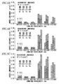
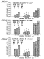
- Figs. 5 to 7 show the results of the experiment.
- Fig. 5 is a graph showing the results in the case of mixing ratio (I), that is, the respective colors of B1, Gr, Ye, and Re lights are mixed at a luminance ratio of 1:1.
- each of Figs. 5A , 6A , and 7A shows a case where background luminance is 0.1 cd/m 2
- each of Figs. 5B , 6B , and 7B shows a case where background luminance is 0.3 cd/m 2
- each of Figs. 5C , 6C , and 7C shows a case where background luminance is 0.5 cd/m 2 .
- the results for three examinees are shown by graphs A, B, and C, respectively.
- the "combined wavelength” represented on the horizontal axis is the wavelength corresponding to the mixed color light where colors are mixed so as to correspond to six kinds of combinations
- the "added luminance” represented on the vertical axis is the luminance corresponding to a detection limit.
- Small luminance means that a detection limit is small, that is, the examinee's discrimination ability is high.
- blue light or mixed color light including blue light is mixed with white light even though the amount of the blue light or mixed color light is small, there is a possibility that the visibility of a lane marker is improved.
- the mixed color light is mixed color light of blue light and red light.
- the mixed color light is mixed color light of blue light and red light as described above, there is a possibility that the visibility of a pedestrian is also improved by the addition of red light of which the reflectance is high on the human skin.
- a halogen lamp specifically, a fog lamp using a halogen bulb as a light source.
- the left lane marker was additionally irradiated with blue light (470 nm) and red light (620 nm) by the light-emitting diode and the left and right lane markers were compared with each other in terms of visibility.
- the light irradiated from the halogen lamp of a base was reduced for the left lane marker additionally irradiated with the mixed color light (blue light + red light) so that the luminance of the left lane marker was equal to that of the right lane marker.
- the ratio of the mixed color light (blue light + red light) to be added was set to the luminance of three levels of 17.2%, 8.0%, and 4.5% of the luminance of the light that was irradiated from the headlamp using a halogen bulb as a light source.
- the mixing ratios of blue light and red light were set to five ratios, that is, 0% + 100%, 25% + 75%, 50% + 50%, 75% + 25%, and 100% + 0% at an interval of 25%.
- the chromaticity of the left lane marker which was irradiated with the mixed color light (blue light + red light), was measured together with the chromaticity of the right lane marker.
- the evaluation of the visibility of the lane marker was performed by organoleptic evaluation based on the impression of each of four examinees.
- Fig. 8 is a table showing the results of the evaluation of the visibility of the lane markers that areaggregated as the impressions of the four examinees. The impressions of four examinees are disclosed in the respective sections of the table shown in Fig. 8 .
- Fig. 9 is a view showing a relationship between the evaluation and chromaticity of the lane marker.
- the evaluation results of the visibility of the lane marker based on the impressions of the four examinees are shown by rough area division in Fig. 9 .
- the impressions of four examinees were different from each other in terms of the mixing ratio of blue light and red light and the ratio of the mixed color light to the light irradiated from the headlamp.
- the visibility in the peripheral visual field was particularly improved in a portion surrounded by a thick frame in the table of Fig. 8 (that is, when the ratio of blue light was 75% or more, the ratio of the mixed color light (color light ratio) was 4.5% or 8.0%, and when the ratio of blue light was in the range of 25 to 75% and the color light ratio is 8.0%).
- the portion surrounded by the thick frame might be understood as a highly evaluated area even on the chromaticity diagram shown in Fig. 9 .
- the highly evaluated area was a portion near blue light in a white range defined by the ECE standard and an area between the white range and a portion slightly shifted toward the blue light side.
- the lane marker is irradiated with irradiation light having a color light ratio and a mixing ratio of the portion surrounded by the thick frame so that the chromaticity of the lane marker is in a predetermined chromaticity range, it is considered that the visibility of the lane marker can be sufficiently improved.
- the vehicle lamp 10 according to this embodiment has superimposed and formed the lane marker irradiation light distribution pattern PA on the low-beam light distribution pattern PL.
- the additional lamp unit 30 for forming the lane marker irradiation light distribution pattern PA has employed the structure for irradiating blue light on the basis of the above-mentioned conclusions, it may be possible to sufficiently improve the visibility of the lane marker LM1.
- the lane marker LM1 is generally a white line, it may be possible to further improve the visibility of the lane marker LM1 by irradiating the lane marker LM1 with blue light.
- the light-emitting element 32 for emitting blue light (specifically, blue light-emitting diode) has been used as the light source of the additional lamp unit 30 in this embodiment. Accordingly, it may be possible to form the lane marker irradiation light distribution pattern PA by blue light with a simple structure.
- the low-beam light distribution pattern PL is formed by white light of which the color temperature is lower as compared to when a discharge bulb is used as the light source.
- the low-beam light distribution pattern PL is formed of a light distribution pattern that slightly takes on a yellow tinge, so that the visibility of the lane marker LM1 is slightly lowered. Therefore, as in this embodiment, it is particularly effective that the lane marker irradiation light distribution pattern PA is formed by blue light with the additional lamp unit 30.
- the maximum luminance of the lane marker irradiation light distribution pattern PA is equal to or lower than 10% of the maximum luminance of a portion of the low-beam light distribution pattern PL overlapping the lane marker irradiation light distribution pattern PA. Accordingly, it may be possible to prevent a driver of the subject vehicle from feeling the discomfort that is caused by the excessive increase of the luminance of the lane marker irradiation light distribution pattern PA and a strong blue tinge.
- an advantage of improving the visibility of the lane marker LM 1 is obtained by a small amount of blue light as described above. Accordingly, even though the low-beam light distribution pattern PL slightly takes on a yellow tinge, it may be possible to remove concern that a driver of the subject vehicle feels discomfort.
- the lane marker irradiation light distribution pattern PA may always be superimposed and formed when the low-beam light distribution pattern PL is formed.
- the lane marker irradiation light distribution pattern may be superimposed and formed only when the visibility of the lane marker LM1 or the like needs to be improved.
- the maximum luminance of the lane marker irradiation light distribution pattern PA is equal to or lower than 10% of the maximum luminance of a portion of the low-beam light distribution pattern PL overlapping the lane marker irradiation light distribution pattern PA.
- the maximum luminance of the lane marker irradiation light distribution pattern is equal to or lower than 8% of the maximum luminance of the portion of the low-beam light distribution pattern overlapping the lane marker irradiation light distribution pattern, it may be possible to substantially and reliably remove concern that a driver of the subject vehicle feels discomfort.
- the mixed color light including blue light is the mixed color light of blue light and red light
- a light-emitting chip for emitting red light may be disposed adjacent to a light-emitting chip 32a for emitting blue light.
- the main lamp unit 20 has been adapted to form the lane marker irradiation light distribution pattern PA that irradiates the lane marker LM I close to the shoulder of a road.
- the main lamp unit may be adapted to form a lane marker irradiation light distribution pattern that irradiates the lane marker LM2 of a center line or the lane marker LM3 of the opposite lane.
- the light source of the main lamp unit 20 is the H4 halogen bulb 22
- the light source even when a discharge bulb, a white light-emitting diode, or the like is used as the light source, it may be possible to obtain substantially the same operational advantages as those of the above-mentioned embodiment.
- the structure of the vehicle lamp 10, which is used under a traffic regulation where vehicles must keep to the left, has been described in the above-mentioned embodiment. However, a structure symmetrical to the structure of the vehicle lamp 10 may be applied under a traffic regulation where vehicles must keep to the right.
Landscapes
- Engineering & Computer Science (AREA)
- Mechanical Engineering (AREA)
- General Engineering & Computer Science (AREA)
- Non-Portable Lighting Devices Or Systems Thereof (AREA)
- Led Device Packages (AREA)
Abstract
Description
- The present invention relates to a vehicle headlamp adapted to superimpose a lane marker irradiation light distribution pattern over a light distribution pattern.
- In the past, there has been known a vehicle lamp including a lamp unit that is adapted to selectively form a low-beam light distribution pattern or a high-beam light distribution pattern as a light distribution pattern for a headlamp.
-
JP-A-2003-59317 - Meanwhile,
JP-A-2009-126444 JP-A-2009-126444 - The vehicle lamp disclosed in
JP-A-2003-59317 - However, in the vehicle lamp disclosed in
JP-A-2003-59317 - Meanwhile, the vehicle lamp disclosed in
JP-A-2009-126444 - However, in the vehicle lamp disclosed in
JP-A-2009-126444 - Exemplary embodiments of the present invention may address the above disadvantages and other disadvantages not described above. However, the present invention is not required to overcome the disadvantages described above or any other disadvantages, and thus, an exemplary embodiment of the present invention may not overcome any disadvantages.
- Accordingly, it is an illustrative aspect of the present invention to provide a vehicle lamp capable of superimposing and forming a lane marker irradiation light distribution pattern on a light distribution pattern for a headlamp and can sufficiently improve the visibility of a lane marker.
- According to one or more aspects of the present invention, there is provided a vehicle lamp including a main lamp unit that forms a main light distribution pattern for a headlamp, and an additional lamp unit that emits blue light or mixed light including blue light to form a lane marker irradiation light distribution pattern, wherein the lane marker irradiation light distribution patten is superimposed onto the main light distribution pattern.
- Other aspects and advantages of the present invention will be apparent from the following description, the drawings and the claims.
-
-
Fig. 1 is a front view of a vehicle lamp according to an exemplary embodiment of the invention; -
Fig. 2 is a perspective view showing a low-beam light distribution pattern and a lane marker irradiation light distribution pattern formed on a virtual vertical screen, which is disposed 25 m ahead of the lamp, by light irradiated forward from the vehicle lamp; -
Figs. 3A and 3B are graphs showing basic experiment results according to the embodiment; -
Fig. 4 is a front view of a dual viewing device used in the main experiment of the embodiment; -
Figs. 5A to 5C are graphs (#1) showing the results of the main experiment; -
Figs. 6A to 6C are graphs (#2) showing the results of the main experiment; -
Figs. 7A to 7C are graphs (#3) showing the results of the main experiment; -
Fig. 8 is a table showing the results of an application experiment of the embodiment; and -
Fig. 9 is a view showing the results of the application experiment using a chromaticity diagram. - According to exemplary embodiments of the present invention, there is provided a vehicle lamp including a main lamp unit that forms a main light distribution pattern for a headlamp, and an additional lamp unit that emits blue light or mixed light including blue light to form a lane marker irradiation light distribution pattern, wherein the lane marker irradiation light distribution patten is superimposed onto the main light distribution pattern.
- The "main lamp unit" is configured to form a light distribution pattern for a headlamp. However, if the main lamp unit has a function of forming at least a low-beam light distribution pattern as the "light distribution pattern" in this case, the main lamp unit may have only a function of forming a low-beam light distribution pattern and may have a function of selectively forming the low-beam light distribution pattern and another light distribution pattern (e.g., a high-beam light distribution pattern).
- The "lane marker irradiation light distribution pattern" indicates a light distribution pattern for irradiating a lane marker on the road surface at the front side of a vehicle. In this case, the lane marker may be a lane marker close to the shoulder of a road, may be a lane marker of an opposite lane or may be both types of lane markers.
- As long as the "additional lamp unit" is configured to emit blue light or mixed color light including blue light, the structure of the additional lamp unit is not particularly limited.
- The term "blue light" means visible light of which the dominant wavelength is 490 nm or less. More preferably, the term blue light means visible light of which the dominant wavelength is 485 nm or less.
- In the "mixed color light including blue light", color light other than blue light included in the mixed color light is not particularly limited.
- According to the present invention, the vehicle lamp is capable of superimposing and forming a lane marker irradiation light distribution pattern on a light distribution pattern for a headlamp. However, since the additional lamp unit for forming the lane marker irradiation light distribution pattern is adapted to irradiate blue light or mixed color light including blue light, it may be possible to obtain the following advantages.
- That is, in the past, a phenomenon known as the Purkinje shift, where a wavelength where the maximum spectral luminous efficacy is shifted to a short-wavelength side as vision proceeds to a scotopic vision from a photopic vision via a mesopic vision has been obtained. This relates to spectral luminous efficacy in a central visual field (that is, a peripheral region of a point of gaze). However, the fact that the same phenomenon occurs even in a peripheral visual field (that is, a peripheral view region) was obtained as a conclusion of the experimental research of the inventors of the invention. Specifically, the following fact has been concluded: if a peripheral visual field is irradiated with blue light or mixed color light including blue light when the entire visual field is irradiated with white light, the visibility of the peripheral visual field is significantly improved even though the luminance of the peripheral visual field is equal to that of the central visual field.
- In the present invention, on the basis of the above-mentioned conclusion, a structure that irradiates blue light or mixed color light including blue light is employed as the additional lamp unit for forming a lane marker irradiation light distribution pattern. Accordingly, it may be possible to improve the visibility of a lane marker. In addition, since the lane marker is generally a white line, it may be possible to further improve the visibility of the lane marker by irradiating the lane marker with blue light or mixed color light including blue light.
- As described above, according to the invention, it may be possible to sufficiently improve the visibility of the lane marker using the vehicle lamp that is adapted to be capable of superimposing and forming the lane marker irradiation light distribution pattern on the light distribution pattern for a headlamp.
- In the above-mentioned structure, color light other than blue light included in the mixed color light, which includes blue light, is not particularly limited as described above. However, if the mixed color light including blue light is mixed color light of blue light and red light, it may be possible to obtain the following operational advantages.
- That is, since red light has high reflectance on the human skin, it may be possible to improve the visibility of not only a lane marker but also a pedestrian by mixing red light with blue light. Here, the term "red light" means visible light of which the dominant wavelength is 600 nm or more. More preferably, the term red light means visible light of which the dominant wavelength is 620 nm or more.
- If a light-emitting element (for example, a light-emitting diode or the like), which emits blue light or mixed color light including blue light, is used as a light source of the additional lamp unit in the above-mentioned structure, it may be possible to form the lane marker irradiation light distribution pattern by blue light or mixed color light including blue light with a simple structure.
- If a light source of the main lamp unit is a halogen bulb in the above-mentioned structure, white light of which the color temperature is lower, as compared to when a discharge bulb or the like is used, as the light source is irradiated and a light distribution pattern for a headlamp, which slightly takes on a yellow tinge, is formed. Accordingly, the visibility of the lane marker is slightly lowered. Therefore, it is particularly effective that the lane marker irradiation light distribution pattern is formed by blue light or mixed color light including blue light.
- If the luminance of the lane marker irradiation light distribution pattern is excessively increased in the above-mentioned structure, a blue tinge becomes strong, so that a driver of a subject vehicle feels discomfort. Accordingly, it is preferable that the maximum luminance of the lane marker irradiation light distribution pattern be set to a value equal to or lower than 10% of the maximum luminance of a portion of the light distribution pattern for a headlamp overlapping the lane marker irradiation light distribution pattern. Further, it is more preferable that the maximum luminance of the lane marker irradiation light distribution pattern be set to a value equal to or lower than 8% of the maximum luminance of the portion of the low-beam light distribution pattern overlapping the lane marker irradiation light distribution pattern.
- Exemplary embodiments of the present invention will now be described with reference to the drawings.
-
Fig. 1 is a front view of avehicle lamp 10 according to this embodiment. - As shown in
Fig. 1 , thevehicle lamp 10 includes a main lamp unit 20, anadditional lamp unit 30, and anextension panel 16. The main lamp unit 20 and theadditional lamp unit 30 are housed in a lamp chamber, which is formed by a planetranslucent cover 12 and alamp body 14, together with theextension panel 16 surrounding the main lamp unit 20 and theadditional lamp unit 30. - The main lamp unit 20 is a parabolic lamp unit. The main lamp unit 20 includes an
H4 halogen bulb 22 that is used as a light source and areflector 24 that reflects forward light emitted from theH4 halogen bulb 22. - Further, the main lamp unit 20 reflects forward light, which is emitted from a low-beam filament or a high-beam filament of the
H4 halogen bulb 22, as diffused light or deflected light by the reflectingsurface 24a of thereflector 24 thereof. Accordingly, the main lamp unit 20 may selectively form a low-beam light distribution pattern and a high-beam light distribution pattern. - The
additional lamp unit 30 is a direct-projection type lamp unit. Theadditional lamp unit 30 includes a light-emittingelement 32 that is used as a light source, and alens 34 that deflects and emits forward light emitted from the light-emittingelement 32. In this case, the light-emittingelement 32 is a light-emitting diode (LED) that emits blue light, and the dominant wavelength of the light emitted from the light-emitting element is set to about 470 nm. - Further, the
additional lamp unit 30 emits forward light, which is emitted from a light-emittingchip 32a of the light-emittingelement 32, as diffused and deflected light by thelens 34 thereof. Accordingly, the additional lamp unit forms a lane marker irradiation light distribution pattern. -
Fig. 2 is a perspective view showing the low-beam light distribution pattern PL and the lane marker irradiation light distribution pattern PA formed on a virtual vertical screen, which is disposed at a position 25 m ahead of the lamp, by light irradiated forward from thevehicle lamp 10. - Meanwhile, in
Fig. 2 , for convenience, thevehicle lamp 10 is arranged in the middle of a traveling lane, on which a subject vehicle travels, on a road having two lanes where vehicles should keep to the left.Fig. 2 shows the road surface at the front side of a vehicle, the low-beam light distribution pattern PL, and the lane marker irradiation light distribution pattern PA. In this state, a lane marker LM1 close to the shoulder of a road is positioned at the left side of the traveling lane on which a subject vehicle is traveling, and a lane marker LM2 of a center line is positioned at the right side of the traveling lane on which a subject vehicle is traveling. The lane markers LM1 and LM2 extend obliquely downward from a H-V point, which is a vanishing point positioned at the front side of the lamp, toward the left and right sides at the same angle. Further, a lane marker LM3 of an opposite lane extends obliquely downward from the H-V point toward the right side at an angle close to an angle corresponding to the horizontal line as compared to the lane marker LM2 of the center line. - As shown in
Fig. 2 , the low-beam light distribution pattern PL is a left low-beam light distribution pattern. The low-beam light distribution pattern PL has a cut-off line, which is formed of a horizontal cut-off line CL1 and an oblique cut-off line CL2, at the upper end edge thereof. In this case, the horizontal cut-off line CL1 is formed at one side of a V-V line, which is a vertical line passing through the H-V point, close to the opposite lane. The oblique cut-off line CL2 is formed so as to be inclined upward (for example, 15°) toward the traveling lane from an intersection of the horizontal cut-off line CL1 and the V-V line. Further, an elbow point E, which is the intersection of the horizontal cut-off line CL1 and the oblique cut-off line CL2, is positioned below the H-V point by an angle of about 0.5 to 0.6°. - The low-beam light distribution pattern PL is formed by the light that is irradiated from the main lamp unit 20 using the
H4 halogen bulb 22 as a light source (that is, the low-beam light distribution pattern is formed by white light of which the color temperature is lower as compared to when a discharge bulb or the like is used as the light source). Accordingly, the low-beam light distribution pattern is a light distribution pattern that slightly takes on a yellow tinge. - Meanwhile, the lane marker irradiation light distribution pattern PA is a substantially spot-like light distribution pattern that is slightly elongated so as to extend downward toward the left side from a point positioned at the lower left side of the elbow point E of the low-beam light distribution pattern PL. The lane marker irradiation light distribution pattern PA is formed while being superimposed on the low-beam light distribution pattern PL. Further, the lane marker irradiation light distribution pattern PA is formed so as to irradiate the lane marker LM1, which is close to the shoulder of a road, among three lane markers LM1, LM2, and LM3.
In addtition, inFig. 2 , the lane marker irradiation light distribution pattern PA is completely superimposed on the low-beam light distribution pattern PL, but the exemplary embodiment of the invention is not limited thereto. For example, the lane marker irradiation light distribution pattern PA may be partially superimposed on the low-beam light distribution pattern PL. - The lane marker irradiation light distribution pattern PA is formed by the light irradiated from the
additional lamp unit 30 using the light-emittingelement 32, which emits blue light, as a light source. Accordingly, the lane marker irradiation light distribution pattern is a blue light distribution pattern. In this case, the maximum luminance of the lane marker irradiation light distribution pattern PA is set to a value that is equal to or lower than 10% (for example, a value of about 5%) of the maximum luminance of a portion of the low-beam light distribution pattern PL overlapping the lane marker irradiation light distribution pattern PA. Accordingly, the portion where the low-beam light distribution pattern PL overlaps the lane marker irradiation light distribution pattern PA somewhat takes on a blue tinge as compared to other portions. However, there is no concern that a driver of the subject vehicle feels discomfort due to this. - The details of experimental research concerning the employment of the structure of the
vehicle lamp 10 according to this embodiment will be described below. - From the results of the experimental research to be described below, as a conclusion, the inventors of the invention deduced the fact that if a peripheral visual field is irradiated with blue light or mixed color light including blue light when the entire visual field is irradiated with white light, the visibility of the peripheral visual field is significantly improved even though the luminance of the peripheral visual field is equal to that of the central visual field.
- The experimental research was performed through three experiments, that is, a basic experiment, a main experiment, and an application experiment. Each of the three experiments will be described below.
- Relationships between a recognition rate/recognition time and color stimulus of monochromatic light were examined to study the wavelength distribution of illumination light that is easily recognized in response to a visual object (for example, a lane marker, a pedestrian, or the like) under a mesopic environment.
- While white light was irradiated on a gray screen from a projector lamp, Landolt rings (that is, the shape of the letter "C" of the alphabet) were depicted at four positions on the screen by a plurality of kinds of color light. In this case, the directions of the respective Landolt rings were randomly set. Further, the recognition rates of the Landolt rings (the ratio of the correct response to the directions of the Landolt rings) and time taken for examinees to recognize the respective Landolt rings were measured from the examinees' responses to the directions of the respective Landolt rings.
- In this case, in order to create the mesopic environment, background luminance was set to 0.3 cd/m2 (= square meter) by the light irradiated from the projector lamp.
- Further, white light and four kinds of monochromatic light, that is, blue light, green light, yellow light, and red light were used as color light used for depicting the Landolt rings.
- The experiment was performed by three examinees.
-
Fig. 3 shows the results of the experiment. -
Fig. 3A is a graph showing a relationship between the recognition rates of the Landolt rings and the level of contrast between the Landolt rings, which are formed on the screen, and the background thereof. Further,Fig. 3B is a graph showing a relationship between the level of contrast and the recognition time. - From the graphs shown in
Fig. 3A , the following was found: when contrast is reduced, a recognition rate is rapidly lowered in the cases of white light, green light, and yellow light. In contrast, even though contrast is reduced, the recognition rate is scarcely lowered in the cases of blue light and red light. The recognition rate is particularly high in the case of blue light. - Further, from the graphs shown in
Fig. 3B , the following was found: recognition time is substantially constant regardless of the level of contrast in the cases of the other color lights except for yellow light, and recognition time is slightly shorter in the case of blue light. - It makes no sense at all that blue light or red light is used alone in a headlamp. Accordingly, a detection limit was measured in the case of mixed color light obtained by mixing blue light with other color light.
- Meanwhile, a detection limit, where an examinee feels a difference in color between white light and mixed light when monochromatic light is gradually added to white light, is referred to as a "purity discrimination threshold". However, since the color light to be added is mixed color light in the main experiment, the detection limit is referred to as a "detection limit".
- While white light was irradiated on a gray screen from a projector lamp in a darkroom having a brightness of about 1 Lux, the luminance (that is, background luminance) of the screen was set to three levels, that is, 0.1, 0.3, and 0.5 cd/m2
- Mixed color light obtained by the mixture of two of blue light (Bl: 405 nm), green light (Gr: 523 nm), yellow light (Ye: 572 nm), and red light (Re: 680 nm) was used as the mixed color light.
- In this case, the following three ratios were set as a mixing ratio.
- (I) A mixing ratio where the respective colors of the color lights are mixed at a luminance ratio of 1:1 while focusing on a "luminance value".
- (II) A mixing ratio where the respective colors are mixed (except for a Ye component) at a brightness coefficient-luminance ratio (i.e., a luminance ratio of Re : Gr : Bl = 1: 4.59 : 0.06) while focusing on the "feeling of brightness".
- (III) A mixing ratio where each color light is mixed so that the luminance of the Ye component is added to the luminance of each of the Re, Gr, and Bl components at a luminance ratio of Re, Gr, and B1: Ye = 1: 4.
- The experiment was performed under the respective conditions (I) to (III) at the three levels of background luminance by three examinees.
- This experiment was performed using a
dual viewing device 100 shown inFig. 4 . - The
dual viewing device 100 is configured so that aprism 106 is disposed at a connectingportion 104 between a pair of (left and right) integratingspheres light source units spheres spheres light source unit 110 for providing arbitrary color light into the integratingsphere 102R and ameasurement unit 112 for measuring luminance are mounted on theright integrating sphere 102R. - The
dual viewing device 100 generates low-luminance white light, which becomes adaptable light, on one visual field (the dual visual field corresponding to the integratingsphere 102L) of the dual visual fields, and generates stimulus light by mixing color light with white reference light on the other visual field (the dual visual field corresponding to the integratingsphere 102R). Then, the dual viewing device forms the dual visual fields by combining the white light with the stimulus light with theprism 106 that is provided in the middle of the dual viewing device. In this case, thedual viewing device 100 is automatically adjusted so that the luminances of the dual visual fields (that is, the luminances of the pair of (left and right) prism surfaces 106L and 106R) are equal to each other. - This experiment was performed with the following procedure.
- Firstly, before the start of the experiment, examinees are adapted to darkness for 30 minutes under a low-illuminance environment.
- Next, the same low-luminance white light was provided to the pair of (left and right) integrating
spheres prism 106 from a position that is distant from the prism surfaces at the front side of the prism surfaces by a distance of about 50 cm. - In this state, the examinee determined a detection limit, where the examinee felt a difference in color between both the prism surfaces 106L and 106R, by the examinee adding mixed color light to only the right view region (integrating
sphere 102R) by the examinee's own operation. At the time of the determination of the detection limit, luminance added at this time was measured by an observer. -
Figs. 5 to 7 show the results of the experiment. -
Fig. 5 is a graph showing the results in the case of mixing ratio (I), that is, the respective colors of B1, Gr, Ye, and Re lights are mixed at a luminance ratio of 1:1.Fig. 6 is a graph showing the results in the case of mixing ratio (II), that is, the case where the respective colors are mixed at a luminance ratio of Re : Gr : Bl = 1 : 4.59 : 0.06.Fig. 7 is a graph showing the results in the case of mixing ratio (III), that is, the case where the respective color lights are mixed at a luminance ratio of Re, Gr, and B1: Ye = 1:4. - In
Figs. 5 to 7 , each ofFigs. 5A ,6A , and7A shows a case where background luminance is 0.1 cd/m2, each ofFigs. 5B ,6B , and7B shows a case where background luminance is 0.3 cd/m2, and each ofFigs. 5C ,6C , and7C shows a case where background luminance is 0.5 cd/m2. Further, in each of these cases, the results for three examinees are shown by graphs A, B, and C, respectively. - In each of these graphs, the "combined wavelength" represented on the horizontal axis is the wavelength corresponding to the mixed color light where colors are mixed so as to correspond to six kinds of combinations, and the "added luminance" represented on the vertical axis is the luminance corresponding to a detection limit. Small luminance means that a detection limit is small, that is, the examinee's discrimination ability is high.
- From the graphs shown in
Figs. 5 to 7 , the following was found: if blue light is mixed with other color light even when a mixing ratio is any one of (I), (II), and (III), a detection limit is significantly reduced in any combination as compared to when color lights except for blue light are mixed with each other. - In this case, from the graphs shown in
Figs. 6 and7 , the following was found: if blue light is mixed with the other color lights, a detection limit is sufficiently reduced even though the luminance ratio of the blue light is small. - Further, from the graphs shown in
Fig. 6 , the following was found: if color light to be mixed with blue light is red light, a detection limit is reduced as compared to when the color light to be mixed with blue light is green light. - Furthermore, from the graphs shown in
Fig. 7 , the following was found: even when the color light to be mixed with blue light is yellow light and the luminance ratio of blue light is small, a detection limit is sufficiently reduced. - From the above-mentioned conclusions, the following will be understood.
- If blue light or mixed color light including blue light is mixed with white light even though the amount of the blue light or mixed color light is small, there is a possibility that the visibility of a lane marker is improved.
- In this case, even though white light takes on a yellow tinge, there is the same possibility as the above-mentioned possibility.
- Further, when mixed color light including blue light is employed, it is effective that the mixed color light is mixed color light of blue light and red light.
- If the mixed color light is mixed color light of blue light and red light as described above, there is a possibility that the visibility of a pedestrian is also improved by the addition of red light of which the reflectance is high on the human skin.
- When the results of the main experiment were reflected on the structure of a headlamp, an experiment for confirming the improvement of the visibility of a lane marker was performed.
- Specifically, when mixed color light of blue light and red light was added to the light irradiated from the headlamp as lane marker irradiating light, an appropriate value of the ratio of the mixed color light to be added and an appropriate value of the mixing ratio of the blue light and the red light of the mixed color light were obtained.
- In a darkroom, two lane markers were arranged on right and left sides and each of the lane markers was irradiated by a halogen lamp (specifically, a fog lamp using a halogen bulb as a light source).
- In this state, the left lane marker was additionally irradiated with blue light (470 nm) and red light (620 nm) by the light-emitting diode and the left and right lane markers were compared with each other in terms of visibility.
- In this case, the light irradiated from the halogen lamp of a base was reduced for the left lane marker additionally irradiated with the mixed color light (blue light + red light) so that the luminance of the left lane marker was equal to that of the right lane marker.
- The ratio of the mixed color light (blue light + red light) to be added was set to the luminance of three levels of 17.2%, 8.0%, and 4.5% of the luminance of the light that was irradiated from the headlamp using a halogen bulb as a light source.
- Further, the mixing ratios of blue light and red light were set to five ratios, that is, 0% + 100%, 25% + 75%, 50% + 50%, 75% + 25%, and 100% + 0% at an interval of 25%.
- In this case, the chromaticity of the left lane marker, which was irradiated with the mixed color light (blue light + red light), was measured together with the chromaticity of the right lane marker. Moreover, the evaluation of the visibility of the lane marker was performed by organoleptic evaluation based on the impression of each of four examinees.
-
Fig. 8 is a table showing the results of the evaluation of the visibility of the lane markers that areaggregated as the impressions of the four examinees. The impressions of four examinees are disclosed in the respective sections of the table shown inFig. 8 . - Further,
Fig. 9 is a view showing a relationship between the evaluation and chromaticity of the lane marker. The evaluation results of the visibility of the lane marker based on the impressions of the four examinees are shown by rough area division inFig. 9 . - As shown in the table of
Fig. 8 , the impressions of four examinees were different from each other in terms of the mixing ratio of blue light and red light and the ratio of the mixed color light to the light irradiated from the headlamp. - Moreover, it was found that the visibility in the peripheral visual field was particularly improved in a portion surrounded by a thick frame in the table of
Fig. 8 (that is, when the ratio of blue light was 75% or more, the ratio of the mixed color light (color light ratio) was 4.5% or 8.0%, and when the ratio of blue light was in the range of 25 to 75% and the color light ratio is 8.0%). - The portion surrounded by the thick frame might be understood as a highly evaluated area even on the chromaticity diagram shown in
Fig. 9 . The highly evaluated area was a portion near blue light in a white range defined by the ECE standard and an area between the white range and a portion slightly shifted toward the blue light side. - Accordingly, if the lane marker is irradiated with irradiation light having a color light ratio and a mixing ratio of the portion surrounded by the thick frame so that the chromaticity of the lane marker is in a predetermined chromaticity range, it is considered that the visibility of the lane marker can be sufficiently improved.
- Next, the operational advantages of this embodiment will be described.
- The
vehicle lamp 10 according to this embodiment has superimposed and formed the lane marker irradiation light distribution pattern PA on the low-beam light distribution pattern PL. However, since theadditional lamp unit 30 for forming the lane marker irradiation light distribution pattern PA has employed the structure for irradiating blue light on the basis of the above-mentioned conclusions, it may be possible to sufficiently improve the visibility of the lane marker LM1. - In addition, since the lane marker LM1 is generally a white line, it may be possible to further improve the visibility of the lane marker LM1 by irradiating the lane marker LM1 with blue light.
- As described above, according to this embodiment, it may be possible to sufficiently improve the visibility of the lane marker LM1 in the
vehicle lamp 10 capable of superimposing the lane marker irradiation light distribution pattern PA on the low-beam light distribution pattern PL. - In particular, the light-emitting
element 32 for emitting blue light (specifically, blue light-emitting diode) has been used as the light source of theadditional lamp unit 30 in this embodiment. Accordingly, it may be possible to form the lane marker irradiation light distribution pattern PA by blue light with a simple structure. - Further, a halogen bulb (specifically, the H4 halogen bulb 22) has been used as the light source of the main lamp unit 20 in this embodiment. Accordingly, the low-beam light distribution pattern PL is formed by white light of which the color temperature is lower as compared to when a discharge bulb is used as the light source. For this reason, the low-beam light distribution pattern PL is formed of a light distribution pattern that slightly takes on a yellow tinge, so that the visibility of the lane marker LM1 is slightly lowered. Therefore, as in this embodiment, it is particularly effective that the lane marker irradiation light distribution pattern PA is formed by blue light with the
additional lamp unit 30. - Furthermore, in this embodiment, the maximum luminance of the lane marker irradiation light distribution pattern PA is equal to or lower than 10% of the maximum luminance of a portion of the low-beam light distribution pattern PL overlapping the lane marker irradiation light distribution pattern PA. Accordingly, it may be possible to prevent a driver of the subject vehicle from feeling the discomfort that is caused by the excessive increase of the luminance of the lane marker irradiation light distribution pattern PA and a strong blue tinge.
- Moreover, an advantage of improving the visibility of the lane marker LM 1 is obtained by a small amount of blue light as described above. Accordingly, even though the low-beam light distribution pattern PL slightly takes on a yellow tinge, it may be possible to remove concern that a driver of the subject vehicle feels discomfort.
- In addition, since an advantage of improving the visibility of the lane marker LM1 is obtained by a small amount of blue light as described above, it may be possible to employ an inexpensive lamp structure where a current-limiting resistor is merely connected to the light-emitting
element 32. - In the above-mentioned embodiment, it goes without saying that the lane marker irradiation light distribution pattern PA may always be superimposed and formed when the low-beam light distribution pattern PL is formed. However, the lane marker irradiation light distribution pattern may be superimposed and formed only when the visibility of the lane marker LM1 or the like needs to be improved.
- In the above-mentioned embodiment, there has been described a case where the maximum luminance of the lane marker irradiation light distribution pattern PA is equal to or lower than 10% of the maximum luminance of a portion of the low-beam light distribution pattern PL overlapping the lane marker irradiation light distribution pattern PA. However, if the maximum luminance of the lane marker irradiation light distribution pattern is equal to or lower than 8% of the maximum luminance of the portion of the low-beam light distribution pattern overlapping the lane marker irradiation light distribution pattern, it may be possible to substantially and reliably remove concern that a driver of the subject vehicle feels discomfort.
- A case where the
additional lamp unit 30 for forming the lane marker irradiation light distribution pattern PA is configured to irradiate blue light has been described in the above-mentioned embodiment. However, even when the additional lamp unit is configured to irradiate mixed color light including blue light, it may be possible to obtain the same operational advantages as those of the above-mentioned embodiment as apparent from the results of the experimental research. - In this case, if the mixed color light including blue light is the mixed color light of blue light and red light, it may be possible to improve the visibility of not only a lane marker LM1 but also a pedestrian by red light of which the reflectance is high on the human skin. Meanwhile, in order to achieve this mixed color light, for example, as the structure of the light-emitting
element 32, a light-emitting chip for emitting red light may be disposed adjacent to a light-emittingchip 32a for emitting blue light. - In the above-mentioned embodiment, the main lamp unit 20 has been adapted to form the lane marker irradiation light distribution pattern PA that irradiates the lane marker LM I close to the shoulder of a road. However, the main lamp unit may be adapted to form a lane marker irradiation light distribution pattern that irradiates the lane marker LM2 of a center line or the lane marker LM3 of the opposite lane.
- A case where the lane marker irradiation light distribution pattern PA is superimposed on the low-beam light distribution pattern PL has been described in the above-mentioned embodiment. However, even though the lane marker irradiation light distribution pattern PA is superimposed on the high-beam light distribution pattern, it may be possible to obtain substantially the same operational advantages as those of the above-mentioned embodiment.
- A case where the light source of the main lamp unit 20 is the
H4 halogen bulb 22 has been described in the above-mentioned embodiment. However, even when a discharge bulb, a white light-emitting diode, or the like is used as the light source, it may be possible to obtain substantially the same operational advantages as those of the above-mentioned embodiment. - The structure of the
vehicle lamp 10, which is used under a traffic regulation where vehicles must keep to the left, has been described in the above-mentioned embodiment. However, a structure symmetrical to the structure of thevehicle lamp 10 may be applied under a traffic regulation where vehicles must keep to the right.
Claims (9)
- A vehicle lamp comprising:a main lamp unit that forms a main light distribution pattern for a headlamp; andan additional lamp unit that emits blue light or mixed light including blue light to form a lane marker irradiation light distribution pattern, wherein the lane marker irradiation light distribution patten is superimposed onto the main light distribution pattern.
- The vehicle lamp according to claim 1, wherein the additional lamp unit emits mixed light including blue light and red light.
- The vehicle lamp according to claim 1 or 2,
wherein the additional lamp unit comprises a light-emitting element that emits blue light or mixed light including blue light. - The vehicle lamp according to any one of claims 1 to 3,
wherein the main lamp unit comprises a halogen bulb. - The vehicle lamp according to any one of claims 1 to 4,
wherein the maximum luminance of the lane marker irradiation light distribution pattern is equal to or less than 10% of the maximum luminance of the main light distribution pattern onto which the lane marker irradiation light distribution pattern is superimposed. - The vehicle lamp according to any one of claims 1 to 5,
wherein the maximum luminance of the lane marker irradiation light distribution pattern is equal to or less than 8% of the maximum luminance of the main light distribution pattern onto which the lane marker irradiation light distribution pattern is superimposed. - The vehicle lamp according to any one of claims 1 to 6, wherein a ratio of the blue light with respect to the mixed light is in a range of about 25% to about 75%, and
wherein the maximum luminance of the lane marker irradiation light distribution pattern is about 8% of the maximum luminance of the main light distribution pattern onto which the lane marker irradiation light distribution pattern is superimposed. - The vehicle lamp according to claim 1, wherein the lane marker irradiation light distribution patten is partially superimposed onto the main light distribution pattern.
- The vehicle lamp according to claim 1, wherein the lane marker irradiation light distribution patten is completely superimposed onto the main light distribution pattern.
Applications Claiming Priority (1)
| Application Number | Priority Date | Filing Date | Title |
|---|---|---|---|
| JP2009278211A JP5520023B2 (en) | 2009-12-08 | 2009-12-08 | Lighting fixtures for vehicles |
Publications (2)
| Publication Number | Publication Date |
|---|---|
| EP2340965A1 true EP2340965A1 (en) | 2011-07-06 |
| EP2340965B1 EP2340965B1 (en) | 2018-10-17 |
Family
ID=43732147
Family Applications (1)
| Application Number | Title | Priority Date | Filing Date |
|---|---|---|---|
| EP10194076.5A Not-in-force EP2340965B1 (en) | 2009-12-08 | 2010-12-08 | Vehicle headlamp |
Country Status (3)
| Country | Link |
|---|---|
| US (1) | US8297815B2 (en) |
| EP (1) | EP2340965B1 (en) |
| JP (1) | JP5520023B2 (en) |
Cited By (6)
| Publication number | Priority date | Publication date | Assignee | Title |
|---|---|---|---|---|
| EP2599665A3 (en) * | 2011-12-02 | 2014-07-16 | Volkswagen Aktiengesellschaft | Lighting device and method for projecting warning signals |
| DE102013001286A1 (en) * | 2013-01-25 | 2014-07-31 | GM Global Technology Operations LLC (n. d. Ges. d. Staates Delaware) | Headlight system for motor car, has motor car headlight that is adapted to lane in car transverse direction adjacent to peripheral region to apply light of different spectral compositions |
| DE102013002212A1 (en) * | 2013-02-06 | 2014-08-07 | GM Global Technology Operations LLC (n. d. Ges. d. Staates Delaware) | Lane keeping assistance system for a motor vehicle |
| DE102013016276A1 (en) * | 2013-09-28 | 2015-04-02 | GM GLOBAL TECHNOLOGY OPERATION LLC (n. d. Ges. d. Staates Delaware) | Headlight for a vehicle |
| DE102013017625A1 (en) | 2013-10-23 | 2015-04-23 | Audi Ag | Method for operating a driver assistance device of a motor vehicle and driver assistance device |
| EP3142163A1 (en) * | 2015-09-08 | 2017-03-15 | Konica Minolta, Inc. | Organic electroluminescent element and vehicle lamp fitting |
Families Citing this family (3)
| Publication number | Priority date | Publication date | Assignee | Title |
|---|---|---|---|---|
| JP6374145B2 (en) * | 2013-06-21 | 2018-08-15 | 株式会社小糸製作所 | Vehicle lamp system |
| JP6471756B2 (en) * | 2014-12-09 | 2019-02-20 | 信越化学工業株式会社 | LED light source for in-vehicle headlights |
| DE102017217897A1 (en) * | 2017-10-09 | 2019-04-11 | Osram Gmbh | Lamp with yellow and with white and / or blue light source group |
Citations (9)
| Publication number | Priority date | Publication date | Assignee | Title |
|---|---|---|---|---|
| DE10014301A1 (en) * | 1999-03-26 | 2000-10-12 | Koito Mfg Co Ltd | Vehicle headlamp arrangement uses light from second section to variably expand base light distribution to alter quantity of light or colour depending on driving situation or environment |
| JP2003059317A (en) | 2001-08-09 | 2003-02-28 | Koito Mfg Co Ltd | Headlight device for vehicles |
| US20060285341A1 (en) * | 2005-06-16 | 2006-12-21 | Yasushi Yatsuda | Lamp, optical module, vehicle headlight including the same, and method for controlling color tone of emitted light |
| FR2889869A1 (en) * | 2005-08-16 | 2007-02-23 | Koito Mfg Co Ltd | LAMP FOR VEHICLE |
| US20090086500A1 (en) * | 2007-10-01 | 2009-04-02 | Koito Manufacturing Co., Ltd. | Vehicle headlamp |
| JP2009126444A (en) | 2007-11-27 | 2009-06-11 | Stanley Electric Co Ltd | Vehicle headlamp |
| JP2009211854A (en) * | 2008-03-03 | 2009-09-17 | Nissan Motor Co Ltd | Vehicle headlamp |
| DE102009010508A1 (en) * | 2009-02-25 | 2009-10-01 | Daimler Ag | Lighting device for headlight of motor vehicle, has control unit controlling LEDs independent of each other to adjust respective light intensity of LEDs, and optical unit provided for mixing and optical formation of light emitted by LEDs |
| EP2213512A1 (en) * | 2007-10-31 | 2010-08-04 | Panasonic Corporation | Vehicular lighting device |
-
2009
- 2009-12-08 JP JP2009278211A patent/JP5520023B2/en active Active
-
2010
- 2010-12-07 US US12/962,062 patent/US8297815B2/en not_active Expired - Fee Related
- 2010-12-08 EP EP10194076.5A patent/EP2340965B1/en not_active Not-in-force
Patent Citations (9)
| Publication number | Priority date | Publication date | Assignee | Title |
|---|---|---|---|---|
| DE10014301A1 (en) * | 1999-03-26 | 2000-10-12 | Koito Mfg Co Ltd | Vehicle headlamp arrangement uses light from second section to variably expand base light distribution to alter quantity of light or colour depending on driving situation or environment |
| JP2003059317A (en) | 2001-08-09 | 2003-02-28 | Koito Mfg Co Ltd | Headlight device for vehicles |
| US20060285341A1 (en) * | 2005-06-16 | 2006-12-21 | Yasushi Yatsuda | Lamp, optical module, vehicle headlight including the same, and method for controlling color tone of emitted light |
| FR2889869A1 (en) * | 2005-08-16 | 2007-02-23 | Koito Mfg Co Ltd | LAMP FOR VEHICLE |
| US20090086500A1 (en) * | 2007-10-01 | 2009-04-02 | Koito Manufacturing Co., Ltd. | Vehicle headlamp |
| EP2213512A1 (en) * | 2007-10-31 | 2010-08-04 | Panasonic Corporation | Vehicular lighting device |
| JP2009126444A (en) | 2007-11-27 | 2009-06-11 | Stanley Electric Co Ltd | Vehicle headlamp |
| JP2009211854A (en) * | 2008-03-03 | 2009-09-17 | Nissan Motor Co Ltd | Vehicle headlamp |
| DE102009010508A1 (en) * | 2009-02-25 | 2009-10-01 | Daimler Ag | Lighting device for headlight of motor vehicle, has control unit controlling LEDs independent of each other to adjust respective light intensity of LEDs, and optical unit provided for mixing and optical formation of light emitted by LEDs |
Cited By (7)
| Publication number | Priority date | Publication date | Assignee | Title |
|---|---|---|---|---|
| EP2599665A3 (en) * | 2011-12-02 | 2014-07-16 | Volkswagen Aktiengesellschaft | Lighting device and method for projecting warning signals |
| DE102013001286A1 (en) * | 2013-01-25 | 2014-07-31 | GM Global Technology Operations LLC (n. d. Ges. d. Staates Delaware) | Headlight system for motor car, has motor car headlight that is adapted to lane in car transverse direction adjacent to peripheral region to apply light of different spectral compositions |
| DE102013002212A1 (en) * | 2013-02-06 | 2014-08-07 | GM Global Technology Operations LLC (n. d. Ges. d. Staates Delaware) | Lane keeping assistance system for a motor vehicle |
| DE102013016276A1 (en) * | 2013-09-28 | 2015-04-02 | GM GLOBAL TECHNOLOGY OPERATION LLC (n. d. Ges. d. Staates Delaware) | Headlight for a vehicle |
| DE102013017625A1 (en) | 2013-10-23 | 2015-04-23 | Audi Ag | Method for operating a driver assistance device of a motor vehicle and driver assistance device |
| DE102013017625B4 (en) * | 2013-10-23 | 2017-03-09 | Audi Ag | Method for operating a driver assistance device of a motor vehicle and driver assistance device |
| EP3142163A1 (en) * | 2015-09-08 | 2017-03-15 | Konica Minolta, Inc. | Organic electroluminescent element and vehicle lamp fitting |
Also Published As
| Publication number | Publication date |
|---|---|
| JP2011124003A (en) | 2011-06-23 |
| US8297815B2 (en) | 2012-10-30 |
| US20110134654A1 (en) | 2011-06-09 |
| JP5520023B2 (en) | 2014-06-11 |
| EP2340965B1 (en) | 2018-10-17 |
Similar Documents
| Publication | Publication Date | Title |
|---|---|---|
| EP2340965B1 (en) | Vehicle headlamp | |
| US9175822B2 (en) | Vehicle headlight | |
| JP4745184B2 (en) | Lighting device | |
| US20190001868A1 (en) | Vehicle headlight and light distribution control device of vehicle headlight | |
| JP2011136651A (en) | Vehicular lighting system | |
| JP5831751B2 (en) | Vehicle headlamp | |
| CN103388756B (en) | Illuminator | |
| JP5907407B2 (en) | Vehicle headlamp | |
| US12391168B2 (en) | Headlight device | |
| TWI588407B (en) | Headlight color temperature control module | |
| US7859430B2 (en) | LED road traffic signal light | |
| JP2020199886A (en) | Head-up display device and head-up display system | |
| JP5668958B2 (en) | Vehicle headlamp | |
| JP2011165441A (en) | Headlamp for vehicle | |
| JP2012206684A (en) | Vehicular illuminating lamp device | |
| JP5637352B2 (en) | Vehicle headlamp | |
| JP6992296B2 (en) | Vehicle lighting | |
| JP5843082B2 (en) | Vehicle headlamp | |
| JP2014143130A (en) | Vehicle head lamp and vehicle | |
| WO2023090426A1 (en) | Personnel lamp and vehicle lamp | |
| JP2016006778A (en) | Vehicular headlamp | |
| JP2009286198A (en) | Lighting system for irradiating pedestrian and vehicular headlamp device | |
| JP2013187009A (en) | Vehicle signal lighting fixture | |
| JP6261345B2 (en) | Vehicle lighting | |
| DE102011120039A1 (en) | Lighting device and method for the projection of warning signals |
Legal Events
| Date | Code | Title | Description |
|---|---|---|---|
| PUAI | Public reference made under article 153(3) epc to a published international application that has entered the european phase |
Free format text: ORIGINAL CODE: 0009012 |
|
| 17P | Request for examination filed |
Effective date: 20101208 |
|
| AK | Designated contracting states |
Kind code of ref document: A1 Designated state(s): AL AT BE BG CH CY CZ DE DK EE ES FI FR GB GR HR HU IE IS IT LI LT LU LV MC MK MT NL NO PL PT RO RS SE SI SK SM TR |
|
| AX | Request for extension of the european patent |
Extension state: BA ME |
|
| 17Q | First examination report despatched |
Effective date: 20160226 |
|
| STAA | Information on the status of an ep patent application or granted ep patent |
Free format text: STATUS: EXAMINATION IS IN PROGRESS |
|
| GRAP | Despatch of communication of intention to grant a patent |
Free format text: ORIGINAL CODE: EPIDOSNIGR1 |
|
| STAA | Information on the status of an ep patent application or granted ep patent |
Free format text: STATUS: GRANT OF PATENT IS INTENDED |
|
| RIC1 | Information provided on ipc code assigned before grant |
Ipc: B60Q 1/18 20060101ALI20180515BHEP Ipc: B60Q 1/00 20060101AFI20180515BHEP Ipc: F21S 41/14 20180101ALI20180515BHEP Ipc: F21S 41/125 20180101ALI20180515BHEP |
|
| INTG | Intention to grant announced |
Effective date: 20180614 |
|
| GRAS | Grant fee paid |
Free format text: ORIGINAL CODE: EPIDOSNIGR3 |
|
| GRAA | (expected) grant |
Free format text: ORIGINAL CODE: 0009210 |
|
| STAA | Information on the status of an ep patent application or granted ep patent |
Free format text: STATUS: THE PATENT HAS BEEN GRANTED |
|
| AK | Designated contracting states |
Kind code of ref document: B1 Designated state(s): AL AT BE BG CH CY CZ DE DK EE ES FI FR GB GR HR HU IE IS IT LI LT LU LV MC MK MT NL NO PL PT RO RS SE SI SK SM TR |
|
| REG | Reference to a national code |
Ref country code: GB Ref legal event code: FG4D |
|
| REG | Reference to a national code |
Ref country code: FR Ref legal event code: PLFP Year of fee payment: 9 |
|
| REG | Reference to a national code |
Ref country code: CH Ref legal event code: EP |
|
| REG | Reference to a national code |
Ref country code: IE Ref legal event code: FG4D |
|
| REG | Reference to a national code |
Ref country code: DE Ref legal event code: R096 Ref document number: 602010054368 Country of ref document: DE Ref country code: AT Ref legal event code: REF Ref document number: 1053595 Country of ref document: AT Kind code of ref document: T Effective date: 20181115 |
|
| REG | Reference to a national code |
Ref country code: NL Ref legal event code: MP Effective date: 20181017 |
|
| PGFP | Annual fee paid to national office [announced via postgrant information from national office to epo] |
Ref country code: GB Payment date: 20181212 Year of fee payment: 13 |
|
| REG | Reference to a national code |
Ref country code: LT Ref legal event code: MG4D |
|
| REG | Reference to a national code |
Ref country code: AT Ref legal event code: MK05 Ref document number: 1053595 Country of ref document: AT Kind code of ref document: T Effective date: 20181017 |
|
| PG25 | Lapsed in a contracting state [announced via postgrant information from national office to epo] |
Ref country code: NL Free format text: LAPSE BECAUSE OF FAILURE TO SUBMIT A TRANSLATION OF THE DESCRIPTION OR TO PAY THE FEE WITHIN THE PRESCRIBED TIME-LIMIT Effective date: 20181017 |
|
| PG25 | Lapsed in a contracting state [announced via postgrant information from national office to epo] |
Ref country code: PL Free format text: LAPSE BECAUSE OF FAILURE TO SUBMIT A TRANSLATION OF THE DESCRIPTION OR TO PAY THE FEE WITHIN THE PRESCRIBED TIME-LIMIT Effective date: 20181017 Ref country code: HR Free format text: LAPSE BECAUSE OF FAILURE TO SUBMIT A TRANSLATION OF THE DESCRIPTION OR TO PAY THE FEE WITHIN THE PRESCRIBED TIME-LIMIT Effective date: 20181017 Ref country code: NO Free format text: LAPSE BECAUSE OF FAILURE TO SUBMIT A TRANSLATION OF THE DESCRIPTION OR TO PAY THE FEE WITHIN THE PRESCRIBED TIME-LIMIT Effective date: 20190117 Ref country code: LV Free format text: LAPSE BECAUSE OF FAILURE TO SUBMIT A TRANSLATION OF THE DESCRIPTION OR TO PAY THE FEE WITHIN THE PRESCRIBED TIME-LIMIT Effective date: 20181017 Ref country code: AT Free format text: LAPSE BECAUSE OF FAILURE TO SUBMIT A TRANSLATION OF THE DESCRIPTION OR TO PAY THE FEE WITHIN THE PRESCRIBED TIME-LIMIT Effective date: 20181017 Ref country code: FI Free format text: LAPSE BECAUSE OF FAILURE TO SUBMIT A TRANSLATION OF THE DESCRIPTION OR TO PAY THE FEE WITHIN THE PRESCRIBED TIME-LIMIT Effective date: 20181017 Ref country code: IS Free format text: LAPSE BECAUSE OF FAILURE TO SUBMIT A TRANSLATION OF THE DESCRIPTION OR TO PAY THE FEE WITHIN THE PRESCRIBED TIME-LIMIT Effective date: 20190217 Ref country code: BG Free format text: LAPSE BECAUSE OF FAILURE TO SUBMIT A TRANSLATION OF THE DESCRIPTION OR TO PAY THE FEE WITHIN THE PRESCRIBED TIME-LIMIT Effective date: 20190117 Ref country code: LT Free format text: LAPSE BECAUSE OF FAILURE TO SUBMIT A TRANSLATION OF THE DESCRIPTION OR TO PAY THE FEE WITHIN THE PRESCRIBED TIME-LIMIT Effective date: 20181017 Ref country code: ES Free format text: LAPSE BECAUSE OF FAILURE TO SUBMIT A TRANSLATION OF THE DESCRIPTION OR TO PAY THE FEE WITHIN THE PRESCRIBED TIME-LIMIT Effective date: 20181017 |
|
| PG25 | Lapsed in a contracting state [announced via postgrant information from national office to epo] |
Ref country code: GR Free format text: LAPSE BECAUSE OF FAILURE TO SUBMIT A TRANSLATION OF THE DESCRIPTION OR TO PAY THE FEE WITHIN THE PRESCRIBED TIME-LIMIT Effective date: 20190118 Ref country code: PT Free format text: LAPSE BECAUSE OF FAILURE TO SUBMIT A TRANSLATION OF THE DESCRIPTION OR TO PAY THE FEE WITHIN THE PRESCRIBED TIME-LIMIT Effective date: 20190217 Ref country code: AL Free format text: LAPSE BECAUSE OF FAILURE TO SUBMIT A TRANSLATION OF THE DESCRIPTION OR TO PAY THE FEE WITHIN THE PRESCRIBED TIME-LIMIT Effective date: 20181017 Ref country code: SE Free format text: LAPSE BECAUSE OF FAILURE TO SUBMIT A TRANSLATION OF THE DESCRIPTION OR TO PAY THE FEE WITHIN THE PRESCRIBED TIME-LIMIT Effective date: 20181017 Ref country code: RS Free format text: LAPSE BECAUSE OF FAILURE TO SUBMIT A TRANSLATION OF THE DESCRIPTION OR TO PAY THE FEE WITHIN THE PRESCRIBED TIME-LIMIT Effective date: 20181017 |
|
| REG | Reference to a national code |
Ref country code: DE Ref legal event code: R097 Ref document number: 602010054368 Country of ref document: DE |
|
| PG25 | Lapsed in a contracting state [announced via postgrant information from national office to epo] |
Ref country code: CZ Free format text: LAPSE BECAUSE OF FAILURE TO SUBMIT A TRANSLATION OF THE DESCRIPTION OR TO PAY THE FEE WITHIN THE PRESCRIBED TIME-LIMIT Effective date: 20181017 Ref country code: IT Free format text: LAPSE BECAUSE OF FAILURE TO SUBMIT A TRANSLATION OF THE DESCRIPTION OR TO PAY THE FEE WITHIN THE PRESCRIBED TIME-LIMIT Effective date: 20181017 Ref country code: DK Free format text: LAPSE BECAUSE OF FAILURE TO SUBMIT A TRANSLATION OF THE DESCRIPTION OR TO PAY THE FEE WITHIN THE PRESCRIBED TIME-LIMIT Effective date: 20181017 |
|
| REG | Reference to a national code |
Ref country code: CH Ref legal event code: PL |
|
| PLBE | No opposition filed within time limit |
Free format text: ORIGINAL CODE: 0009261 |
|
| STAA | Information on the status of an ep patent application or granted ep patent |
Free format text: STATUS: NO OPPOSITION FILED WITHIN TIME LIMIT |
|
| PG25 | Lapsed in a contracting state [announced via postgrant information from national office to epo] |
Ref country code: LU Free format text: LAPSE BECAUSE OF NON-PAYMENT OF DUE FEES Effective date: 20181208 Ref country code: MC Free format text: LAPSE BECAUSE OF FAILURE TO SUBMIT A TRANSLATION OF THE DESCRIPTION OR TO PAY THE FEE WITHIN THE PRESCRIBED TIME-LIMIT Effective date: 20181017 Ref country code: EE Free format text: LAPSE BECAUSE OF FAILURE TO SUBMIT A TRANSLATION OF THE DESCRIPTION OR TO PAY THE FEE WITHIN THE PRESCRIBED TIME-LIMIT Effective date: 20181017 Ref country code: SM Free format text: LAPSE BECAUSE OF FAILURE TO SUBMIT A TRANSLATION OF THE DESCRIPTION OR TO PAY THE FEE WITHIN THE PRESCRIBED TIME-LIMIT Effective date: 20181017 Ref country code: SK Free format text: LAPSE BECAUSE OF FAILURE TO SUBMIT A TRANSLATION OF THE DESCRIPTION OR TO PAY THE FEE WITHIN THE PRESCRIBED TIME-LIMIT Effective date: 20181017 Ref country code: RO Free format text: LAPSE BECAUSE OF FAILURE TO SUBMIT A TRANSLATION OF THE DESCRIPTION OR TO PAY THE FEE WITHIN THE PRESCRIBED TIME-LIMIT Effective date: 20181017 |
|
| REG | Reference to a national code |
Ref country code: IE Ref legal event code: MM4A |
|
| 26N | No opposition filed |
Effective date: 20190718 |
|
| REG | Reference to a national code |
Ref country code: BE Ref legal event code: MM Effective date: 20181231 |
|
| PG25 | Lapsed in a contracting state [announced via postgrant information from national office to epo] |
Ref country code: IE Free format text: LAPSE BECAUSE OF NON-PAYMENT OF DUE FEES Effective date: 20181208 Ref country code: SI Free format text: LAPSE BECAUSE OF FAILURE TO SUBMIT A TRANSLATION OF THE DESCRIPTION OR TO PAY THE FEE WITHIN THE PRESCRIBED TIME-LIMIT Effective date: 20181017 |
|
| PG25 | Lapsed in a contracting state [announced via postgrant information from national office to epo] |
Ref country code: BE Free format text: LAPSE BECAUSE OF NON-PAYMENT OF DUE FEES Effective date: 20181231 |
|
| PG25 | Lapsed in a contracting state [announced via postgrant information from national office to epo] |
Ref country code: CH Free format text: LAPSE BECAUSE OF NON-PAYMENT OF DUE FEES Effective date: 20181231 Ref country code: LI Free format text: LAPSE BECAUSE OF NON-PAYMENT OF DUE FEES Effective date: 20181231 |
|
| PG25 | Lapsed in a contracting state [announced via postgrant information from national office to epo] |
Ref country code: MT Free format text: LAPSE BECAUSE OF NON-PAYMENT OF DUE FEES Effective date: 20181208 |
|
| PGFP | Annual fee paid to national office [announced via postgrant information from national office to epo] |
Ref country code: DE Payment date: 20191126 Year of fee payment: 10 |
|
| PGFP | Annual fee paid to national office [announced via postgrant information from national office to epo] |
Ref country code: FR Payment date: 20191115 Year of fee payment: 10 |
|
| PG25 | Lapsed in a contracting state [announced via postgrant information from national office to epo] |
Ref country code: TR Free format text: LAPSE BECAUSE OF FAILURE TO SUBMIT A TRANSLATION OF THE DESCRIPTION OR TO PAY THE FEE WITHIN THE PRESCRIBED TIME-LIMIT Effective date: 20181017 |
|
| PG25 | Lapsed in a contracting state [announced via postgrant information from national office to epo] |
Ref country code: HU Free format text: LAPSE BECAUSE OF FAILURE TO SUBMIT A TRANSLATION OF THE DESCRIPTION OR TO PAY THE FEE WITHIN THE PRESCRIBED TIME-LIMIT; INVALID AB INITIO Effective date: 20101208 Ref country code: CY Free format text: LAPSE BECAUSE OF FAILURE TO SUBMIT A TRANSLATION OF THE DESCRIPTION OR TO PAY THE FEE WITHIN THE PRESCRIBED TIME-LIMIT Effective date: 20181017 Ref country code: MK Free format text: LAPSE BECAUSE OF NON-PAYMENT OF DUE FEES Effective date: 20181017 |
|
| GBPC | Gb: european patent ceased through non-payment of renewal fee |
Effective date: 20191208 |
|
| PG25 | Lapsed in a contracting state [announced via postgrant information from national office to epo] |
Ref country code: GB Free format text: LAPSE BECAUSE OF NON-PAYMENT OF DUE FEES Effective date: 20191208 |
|
| REG | Reference to a national code |
Ref country code: DE Ref legal event code: R119 Ref document number: 602010054368 Country of ref document: DE |
|
| PG25 | Lapsed in a contracting state [announced via postgrant information from national office to epo] |
Ref country code: FR Free format text: LAPSE BECAUSE OF NON-PAYMENT OF DUE FEES Effective date: 20201231 |
|
| PG25 | Lapsed in a contracting state [announced via postgrant information from national office to epo] |
Ref country code: DE Free format text: LAPSE BECAUSE OF NON-PAYMENT OF DUE FEES Effective date: 20210701 |