EP2340703A1 - Air curtain discharge protection for an agricultural harvester - Google Patents
Air curtain discharge protection for an agricultural harvester Download PDFInfo
- Publication number
- EP2340703A1 EP2340703A1 EP10196476A EP10196476A EP2340703A1 EP 2340703 A1 EP2340703 A1 EP 2340703A1 EP 10196476 A EP10196476 A EP 10196476A EP 10196476 A EP10196476 A EP 10196476A EP 2340703 A1 EP2340703 A1 EP 2340703A1
- Authority
- EP
- European Patent Office
- Prior art keywords
- plenum
- air curtain
- discharge
- disposed
- blower
- Prior art date
- Legal status (The legal status is an assumption and is not a legal conclusion. Google has not performed a legal analysis and makes no representation as to the accuracy of the status listed.)
- Granted
Links
Images



Classifications
-
- A—HUMAN NECESSITIES
- A01—AGRICULTURE; FORESTRY; ANIMAL HUSBANDRY; HUNTING; TRAPPING; FISHING
- A01D—HARVESTING; MOWING
- A01D41/00—Combines, i.e. harvesters or mowers combined with threshing devices
- A01D41/12—Details of combines
- A01D41/1243—Devices for laying-out or distributing the straw
Definitions
- the present invention relates to the improvement of an agricultural harvester. More specifically it relates to an improvement relating to the passage of discharge from the harvester.
- Agricultural harvesting machines such as combines typically include a spreader for propelling crop residue onto a harvested field.
- Crop residue may include stalks, leaves and cobs separated from corn or maize; straw and chaff separated from wheat and other grasses; and stalks, leaves and pods of legumes such as soybeans.
- What is needed is a way to preserve and support free windrow formation of discharge exiting the harvester and to reduce scattering of straw and other materials that decreases the ability of that material to be collected for baling.
- the present invention relates to an agricultural harvester comprising a rear door (16) for expelling discharge (20) in a windrow.
- the havester is provided with a discharge system that comprises a blower having an intake side and a discharge side and a plenum fluidly connected to the discharge side of the blower.
- the plenum is arranged and disposed to distribute air exiting the discharge side of the blower to form an air curtain according to a predetermined profile at a location adjacent discharge exiting a rear door of the agricultural harvester as a windrow.
- the present invention further relates to a kit containing the blower and plenum of the discharge system.
- the kit may further comprise instructions how to assemble the discharge system to a harvester.
- An advantage of the present invention is that the air curtain provides a shield that protects straw and other discharge exiting the harvester from wind that would otherwise have a tendency to disrupt free windrow formation of the exiting discharge.
- a further advantage of the invention is that the use of an air curtain reduces the likelihood of blockage of the discharge path that may occur through the use of a stationary physical barrier.
- Yet another advantage of the present invention is that the air curtain can be used to define the width and other characteristics of the window.
- FIGS 1 through 3 illustrate an agricultural harvester 10 in the form of a combine.
- the combine 10 may include an appropriate header (not shown) which cuts and collects cereal grasses, corn, soybeans or any other plants commonly harvested by combines. The cut, collected plant material is then routed to a thresher within the combine where the grains and seeds are separated from the stalk and any surrounding husk.
- cereal grasses for example, the cereal grains are collected in a hopper in the combine, while the straw, chaff and other residue waste material are expelled from a rear door 16 of the combine 10 as discharge 20.
- the discharge 20 may be scattered as it exits the combine 10, typically through the operation of some device designed to disperse the discharge 20 over a wide area.
- the discharge 20 may instead exit the combine as a windrow 25, in which the discharge 20 is ejected from the rear door 16 and falls freely to the ground by gravity in which a guide 18 may sometimes be provided at the rear door 16 of the combine to guide the discharge 20 away from the combine 10 during its fall.
- the ability for free windrow formation can be significantly impacted by wind, particularly tail winds (as illustrated) or side winds for which access to the discharge is largely unobstructed.
- the combine 10 is equipped with a discharge system 100 that creates an air curtain 150 that combats wind effects to preserve and support free windrow formation of straw and other discharge exiting the combine.
- the discharge system 100 includes a blower 110 that is mounted to the combine 10, as well as a plenum 120 that is arranged and disposed to distribute air from the blower at high velocities to form an air curtain 150 that protects the discharge 20.
- the velocity of the air exiting the plenum 120 is between about 40 and about 80 mph, although the velocity could fall outside of this range under certain operating conditions, including, for example, the height of the plenum 120 above the ground, the density of the discharge, magnitude of the wind, and other factors.
- the air curtain 150 is a thin sheet of air, typically between about 0.6 cm to about 5 cm wide, more typically about 1.3 cm to about 2.5 cm wide, that is directed at a high velocity from the plenum 120 toward the ground.
- the air curtain 150 acts as a barrier that shields wind to lessen its effect on the discharge 20 as it falls from the rear door 16 to the ground.
- the presence of a stationary physical barrier could introduce resistance forces that could slow the movement of discharge 20 as it exits the combine 10, which could, in turn, lead to internal blockages within, and eventual failure of, the combine 10.
- the air curtain 150 overcomes such concerns, as straw or other discharge 20 that may come into contact with the air curtain 150 is forced away from the combine 10 and toward the ground by the downward motion of the air.
- the blower 110 can be any suitable fan, compressor or other device for drawing air through an intake and discharging it at a higher velocity. It will be appreciated that the capacity of the particular blower needed in terms of total cubic meter per minute in a particular circumstance may depend on several factors including the length of any ducting 115 from the blower 110 to the plenum 120, the desired velocity of the air in the air curtain 150 to be formed, and the volume of the air curtain 150 desired to be achieved, which is a function of the thickness and area of the air curtain 150.
- blowers 110 connected to a single plenum 120 to increase the total volume of air passing to the plenum 120 and/or to more evenly distribute the air through the plenum to obtain a more uniform velocity profile in the air curtain 150.
- the blower 110 may be a variable speed blower so that the velocity of the air in the air curtain 150 can be adjustably increased or decreased depending on wind speed to avoid committing unnecessary power from the combine's engine to power the blower 150 in low wind conditions when a lesser velocity in the air curtain 150 could still provide the shielding effect sought to be achieved.
- the blower 110 may be coupled to be in electronic communication with a wind speed sensor 130 which are sometimes mounted to combines and other agricultural equipment.
- the wind speed sensor 130 ( Figures 1-3 ) can be used to automatically adjust blower speed to account for detected changes in wind speed.
- the plenum 120 is fluidly connected to the blower 110, either directly or through ductwork 115, to carry the air from the blower 110 to an inlet 122 of the plenum 120.
- the plenum 120 is a chamber having a narrow outlet 124 and is configured in an arrangement to form the air curtain 150 according to a predetermined profile.
- the plenum 120 is typically constructed as a molded plastic part, but may be constructed of any other suitable material, such as metal or fiberglass, for example.
- the plenum 120 may be attached directly to the combine 10, such as by affixing it to the rear door 16, or it may be attached indirectly, for example, being supported by the ducting 115 extending from the blower 110 to the plenum inlet 122. In either case, the plenum 120 is near the rear door 16 such that the air curtain 150 formed by the plenum 120 is adjacent the discharge 20 leaving the rear door 16 of the combine 10.
- the air curtain 150 may be formed as to be substantially perpendicular to the ground or it may be angled downwardly away from the rear door.
- the plenum 120 may be configured to form an air curtain having a profile that is substantially planar, while in other embodiments, the air curtain may have a profile that partially surrounds the discharge to form an open channel.
- the plenum forms a complete perimeter to form an air curtain that has a profile corresponding to a closed channel that fully surrounds the sides of the discharge 20.
- the dimensions of the channel may be constant along the length of the air curtain.
- the plenum 120 may be configured so that at least one dimension of the air curtain changes in a uniform manner along its length.
- FIG 5 a top view of an elongated, linear plenum 120 configured to form an air curtain 150 having a planar profile is shown.
- the plenum 120 has an outlet 124 positioned to form an air curtain perpendicular to the ground, although the plenum 120 could be slightly rotated and/or the outlet 124 configured to direct the air curtain away from the rear door of the combine at an angle.
- Figure 6 illustrates a top view of the partial perimeter plenum 120 shown in Figures 1 through 4 , configured to form an air curtain that partially surrounds the discharge to form an open channel.
- a plenum 120 that forms an air curtain 150 to partially surround the discharge 20 may be desired because it provides a single air curtain 150 that protects from both side and tail winds.
- the body of the combine 10 may adequately protect the discharge 20 from headwinds.
- Figure 7 illustrates a top view of a plenum 120 that can be used to provide an air curtain that forms a complete perimeter to form a closed channel that fully surrounds the sides of the discharge 20.
- the body of the combine 10 may protect against headwinds even without an air curtain that establishes a full perimeter, the use of an air curtain 150 that forms an enclosed passage for discharge 20 may further be useful to define characteristics of the windrow 25 to be formed.
- FIG. 9a The cross-sectional view of Figure 9a illustrates how a full perimeter plenum can be arranged to produce a closed channel having a substantially constant dimension along its length. It further illustrates the manner in which the plenum may be arranged to form an air curtain that extends downwardly away from the rear door (not shown) with respect to a plane perpendicular to the ground, to form an angle ⁇ . In embodiments in which the air curtain is so angled, the angle ⁇ may be any angle up to about 60 degrees. In such cases, the air curtain 150 may extend a length of about 1.8 m to 2.7 m from the plenum 120 to the ground.
- Figures 9b and 9c both illustrate embodiments in which the air curtain 150 forms a channel that has a uniform change in dimensions along its length.
- the channel has a uniformly decreasing dimension as the distance from the plenum to the ground increases, while in Figure 9c , the channel has a uniformly increasing dimension along that same distance.
- the passageway formed by the air curtain 150 can be used to define characteristics such as the width and density of windrow formation to further aid in subsequent baling operations.
- the air curtain may be used to define a windrow 25 having a width in the range of about 0.9 to about 1.2 m.
- Figures 9a, 9b, or 9c may be molded or otherwise permanently formed to impart a particular profile to the air curtain 150
- the outlets 124 of the plenum 120 may include a hinge 126 and/or louvers 128 so that the profile of the air curtain 150 can be modified without requiring the plenum 120 to be replaced.
- the configurations shown in Figures 9a, 9b and 9c could each be achieved with the plenum 120 of Figure 7 by adjusting the plenum outlets 124 using the hinges 126.
- closing or opening one or more louvers 128 can also be used to control the profile of the air curtain 150 by allowing or preventing air to exit the plenum 120 at certain locations along its length.
- a discharge system 100 in accordance with exemplary embodiments may be provided as standard or optional equipment on combines and other agricultural harvesters.
- the discharge system may be provided as an after-market add-on kit.
- a kit can include the blower 110 and plenum 120, as well as instructions for mounting the blower 110 to the combine 10 and for fluidly connecting the plenum 120 to the discharge of the blower 110 so that when the kit has been assembled, the plenum 120 is arranged and disposed to form an air curtain 150 adjacent discharge 20 exiting the rear door 16 of the combine 10 as described above.
- plenum 120 has been shown having a uniform cross-section, the invention is not so limited and that depending upon the number of blowers 110 and air curtain 150 to be achieved, a non-uniform plenum 120 may be used in order to obtain uniformity of the air curtain 150.
- the plenum 120 may further include adjustment devices such as flapper valves (not shown) disposed with the plenum 120 to selectively control the shape and relative velocity of different portions of the air curtain.
Landscapes
- Life Sciences & Earth Sciences (AREA)
- Environmental Sciences (AREA)
- Ventilation (AREA)
- Control Of Positive-Displacement Air Blowers (AREA)
Abstract
Description
- The present invention relates to the improvement of an agricultural harvester. More specifically it relates to an improvement relating to the passage of discharge from the harvester.
- Agricultural harvesting machines such as combines typically include a spreader for propelling crop residue onto a harvested field. Crop residue may include stalks, leaves and cobs separated from corn or maize; straw and chaff separated from wheat and other grasses; and stalks, leaves and pods of legumes such as soybeans. In many instances it is desirable for the crop residue to be spread as evenly as possible over the entire width of the harvested swath, to avoid problems resulting from uneven spreading, such as, but not limited to, difficulty in passage of fall tillage tools through residue clumps or thick areas; uneven insulation of the field resulting in uneven field warming and thawing and weed or crop emergence during the following planting season; and increased rodent and insect habitat.
- In some cases, though, particularly where combines are used to harvest cereal grains, there may be a desire to windrow straw or other discharge for subsequent baling. Windrow discharge from the combine can be stalled or disbursed by strong winds that approach the straw perpendicular to its discharge trajectory. As a result, a secondary operation may be necessary to arrange the straw in a narrow dense formation for processing by a baling machine. In some cases, fine straw and other smaller particles that might otherwise be collected for baling are lost altogether, having been disbursed by the wind and fallen through the stubble and being too fine to be recovered by a secondary operation.
- What is needed is a way to preserve and support free windrow formation of discharge exiting the harvester and to reduce scattering of straw and other materials that decreases the ability of that material to be collected for baling.
- The present invention relates to an agricultural harvester comprising a rear door (16) for expelling discharge (20) in a windrow. The havester is provided with a discharge system that comprises a blower having an intake side and a discharge side and a plenum fluidly connected to the discharge side of the blower. The plenum is arranged and disposed to distribute air exiting the discharge side of the blower to form an air curtain according to a predetermined profile at a location adjacent discharge exiting a rear door of the agricultural harvester as a windrow.
- The present invention further relates to a kit containing the blower and plenum of the discharge system. The kit may further comprise instructions how to assemble the discharge system to a harvester.
- An advantage of the present invention is that the air curtain provides a shield that protects straw and other discharge exiting the harvester from wind that would otherwise have a tendency to disrupt free windrow formation of the exiting discharge.
- A further advantage of the invention is that the use of an air curtain reduces the likelihood of blockage of the discharge path that may occur through the use of a stationary physical barrier.
- Yet another advantage of the present invention is that the air curtain can be used to define the width and other characteristics of the window.
- Other features and advantages of the present invention will be apparent from the following more detailed description of preferred embodiments, taken in conjunction with the accompanying drawings which illustrate the invention by way of example.
-
-
Figure 1 is side view of a combine harvester in accordance with an exemplary embodiment. -
Figure 2 is top view of a combine harvester ofFigure 1 . -
Figure 3 is a rear view of a combine harvester ofFigure 1 . -
Figure 4 is a perspective view of an air curtain discharge system in accordance with an exemplary embodiment. -
Figure 5 is a top view of a linear plenum for use with an agricultural harvester discharge system in accordance with an exemplary embodiment. -
Figure 6 is a top view of a plenum arranged and disposed to form an air curtain having a profile that partially surrounds adjacent combine discharge in accordance with a further exemplary embodiment. -
Figure 7 is a top view of a plenum arranged and disposed to form an air curtain having a profile defining a closed perimeter that surrounds adjacent combine discharge in accordance with another exemplary embodiment. -
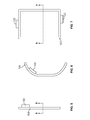
Figure 8 is a cross-sectional view taken along line 8-8 of the plenum ofFigure 5 . -
Figure 9a is a cross-sectional view of an embodiment of the plenum taken along line 9-9 ofFigure 7 configured for an air curtain profile having substantially constant dimensions along its length. -
Figure 9b is a cross-sectional view of an alternate embodiment of the plenum taken along line 9-9 ofFigure 7 configured for an air curtain profile that has a uniform decrease in dimension as the distance from the agricultural harvester to the ground increases. -
Figure 9c is a cross-sectional view of another alternate embodiment of the plenum taken along line 9-9 ofFigure 7 configured for an air curtain profile that has a uniform increase in dimension as the distance from the agricultural harvester to the ground increases. - Wherever possible, the same reference numbers will be used throughout the drawings to refer to the same or like parts.
-
Figures 1 through 3 illustrate anagricultural harvester 10 in the form of a combine. Thecombine 10 may include an appropriate header (not shown) which cuts and collects cereal grasses, corn, soybeans or any other plants commonly harvested by combines. The cut, collected plant material is then routed to a thresher within the combine where the grains and seeds are separated from the stalk and any surrounding husk. In the case of cereal grasses, for example, the cereal grains are collected in a hopper in the combine, while the straw, chaff and other residue waste material are expelled from arear door 16 of thecombine 10 asdischarge 20. - The
discharge 20 may be scattered as it exits thecombine 10, typically through the operation of some device designed to disperse thedischarge 20 over a wide area. In some cases, particularly in situations where thedischarge 20 is to be collected and baled, thedischarge 20 may instead exit the combine as awindrow 25, in which thedischarge 20 is ejected from therear door 16 and falls freely to the ground by gravity in which aguide 18 may sometimes be provided at therear door 16 of the combine to guide thedischarge 20 away from thecombine 10 during its fall. The ability for free windrow formation can be significantly impacted by wind, particularly tail winds (as illustrated) or side winds for which access to the discharge is largely unobstructed. - According to an embodiment of the invention, the
combine 10 is equipped with adischarge system 100 that creates anair curtain 150 that combats wind effects to preserve and support free windrow formation of straw and other discharge exiting the combine. Thedischarge system 100 includes ablower 110 that is mounted to thecombine 10, as well as aplenum 120 that is arranged and disposed to distribute air from the blower at high velocities to form anair curtain 150 that protects thedischarge 20. In some embodiments, the velocity of the air exiting theplenum 120 is between about 40 and about 80 mph, although the velocity could fall outside of this range under certain operating conditions, including, for example, the height of theplenum 120 above the ground, the density of the discharge, magnitude of the wind, and other factors. - The
air curtain 150 is a thin sheet of air, typically between about 0.6 cm to about 5 cm wide, more typically about 1.3 cm to about 2.5 cm wide, that is directed at a high velocity from theplenum 120 toward the ground. As a result, theair curtain 150 acts as a barrier that shields wind to lessen its effect on thedischarge 20 as it falls from therear door 16 to the ground. The presence of a stationary physical barrier could introduce resistance forces that could slow the movement ofdischarge 20 as it exits thecombine 10, which could, in turn, lead to internal blockages within, and eventual failure of, thecombine 10. Theair curtain 150 overcomes such concerns, as straw orother discharge 20 that may come into contact with theair curtain 150 is forced away from thecombine 10 and toward the ground by the downward motion of the air. - As better seen in the perspective view of the
discharge system 100 shown inFigure 4 , theblower 110 can be any suitable fan, compressor or other device for drawing air through an intake and discharging it at a higher velocity. It will be appreciated that the capacity of the particular blower needed in terms of total cubic meter per minute in a particular circumstance may depend on several factors including the length of anyducting 115 from theblower 110 to theplenum 120, the desired velocity of the air in theair curtain 150 to be formed, and the volume of theair curtain 150 desired to be achieved, which is a function of the thickness and area of theair curtain 150. In some cases, it may be desirable to employmultiple blowers 110 connected to asingle plenum 120 to increase the total volume of air passing to theplenum 120 and/or to more evenly distribute the air through the plenum to obtain a more uniform velocity profile in theair curtain 150. - The
blower 110 may be a variable speed blower so that the velocity of the air in theair curtain 150 can be adjustably increased or decreased depending on wind speed to avoid committing unnecessary power from the combine's engine to power theblower 150 in low wind conditions when a lesser velocity in theair curtain 150 could still provide the shielding effect sought to be achieved. In one embodiment, theblower 110 may be coupled to be in electronic communication with awind speed sensor 130 which are sometimes mounted to combines and other agricultural equipment. The wind speed sensor 130 (Figures 1-3 ) can be used to automatically adjust blower speed to account for detected changes in wind speed. - The
plenum 120 is fluidly connected to theblower 110, either directly or throughductwork 115, to carry the air from theblower 110 to aninlet 122 of theplenum 120. Theplenum 120 is a chamber having anarrow outlet 124 and is configured in an arrangement to form theair curtain 150 according to a predetermined profile. Theplenum 120 is typically constructed as a molded plastic part, but may be constructed of any other suitable material, such as metal or fiberglass, for example. Theplenum 120 may be attached directly to thecombine 10, such as by affixing it to therear door 16, or it may be attached indirectly, for example, being supported by theducting 115 extending from theblower 110 to theplenum inlet 122. In either case, theplenum 120 is near therear door 16 such that theair curtain 150 formed by theplenum 120 is adjacent thedischarge 20 leaving therear door 16 of thecombine 10. - The
air curtain 150 may be formed as to be substantially perpendicular to the ground or it may be angled downwardly away from the rear door. In some embodiments, theplenum 120 may be configured to form an air curtain having a profile that is substantially planar, while in other embodiments, the air curtain may have a profile that partially surrounds the discharge to form an open channel. In still other embodiments, the plenum forms a complete perimeter to form an air curtain that has a profile corresponding to a closed channel that fully surrounds the sides of thedischarge 20. In embodiments in which the air curtain forms an open or closed channel, the dimensions of the channel may be constant along the length of the air curtain. Alternatively, theplenum 120 may be configured so that at least one dimension of the air curtain changes in a uniform manner along its length. - Turning to
Figure 5 , a top view of an elongated,linear plenum 120 configured to form anair curtain 150 having a planar profile is shown. As seen in the cross-sectional view shown inFigure 8 , theplenum 120 has anoutlet 124 positioned to form an air curtain perpendicular to the ground, although theplenum 120 could be slightly rotated and/or theoutlet 124 configured to direct the air curtain away from the rear door of the combine at an angle. -
Figure 6 illustrates a top view of thepartial perimeter plenum 120 shown inFigures 1 through 4 , configured to form an air curtain that partially surrounds the discharge to form an open channel. In many circumstances, aplenum 120 that forms anair curtain 150 to partially surround thedischarge 20 may be desired because it provides asingle air curtain 150 that protects from both side and tail winds. The body of thecombine 10 may adequately protect thedischarge 20 from headwinds. -
Figure 7 illustrates a top view of aplenum 120 that can be used to provide an air curtain that forms a complete perimeter to form a closed channel that fully surrounds the sides of thedischarge 20. Although the body of thecombine 10 may protect against headwinds even without an air curtain that establishes a full perimeter, the use of anair curtain 150 that forms an enclosed passage fordischarge 20 may further be useful to define characteristics of thewindrow 25 to be formed. - The cross-sectional view of
Figure 9a illustrates how a full perimeter plenum can be arranged to produce a closed channel having a substantially constant dimension along its length. It further illustrates the manner in which the plenum may be arranged to form an air curtain that extends downwardly away from the rear door (not shown) with respect to a plane perpendicular to the ground, to form an angle θ. In embodiments in which the air curtain is so angled, the angle θ may be any angle up to about 60 degrees. In such cases, theair curtain 150 may extend a length of about 1.8 m to 2.7 m from theplenum 120 to the ground. -
Figures 9b and 9c both illustrate embodiments in which theair curtain 150 forms a channel that has a uniform change in dimensions along its length. InFigure 9b , the channel has a uniformly decreasing dimension as the distance from the plenum to the ground increases, while inFigure 9c , the channel has a uniformly increasing dimension along that same distance. In this manner, the passageway formed by theair curtain 150 can be used to define characteristics such as the width and density of windrow formation to further aid in subsequent baling operations. In one embodiment, the air curtain may be used to define awindrow 25 having a width in the range of about 0.9 to about 1.2 m. - Although shown as a cross-sectional view of the
full perimeter plenum 120 illustrated inFigure 7 , it will be appreciated that the principles described inFigures 9a through 9c apply in a similar manner with respect to apartial perimeter plenum 120 as illustrated inFigure 6 . - While any one of
Figures 9a, 9b, or 9c may be molded or otherwise permanently formed to impart a particular profile to theair curtain 150, these Figures further demonstrate that theoutlets 124 of theplenum 120 may include ahinge 126 and/orlouvers 128 so that the profile of theair curtain 150 can be modified without requiring theplenum 120 to be replaced. For example, the configurations shown inFigures 9a, 9b and 9c could each be achieved with theplenum 120 ofFigure 7 by adjusting theplenum outlets 124 using thehinges 126. Likewise, closing or opening one ormore louvers 128 can also be used to control the profile of theair curtain 150 by allowing or preventing air to exit theplenum 120 at certain locations along its length. - A
discharge system 100 in accordance with exemplary embodiments may be provided as standard or optional equipment on combines and other agricultural harvesters. Alternatively, the discharge system may be provided as an after-market add-on kit. Such a kit can include theblower 110 andplenum 120, as well as instructions for mounting theblower 110 to thecombine 10 and for fluidly connecting theplenum 120 to the discharge of theblower 110 so that when the kit has been assembled, theplenum 120 is arranged and disposed to form anair curtain 150adjacent discharge 20 exiting therear door 16 of thecombine 10 as described above. - It will be appreciated that while the
plenum 120 has been shown having a uniform cross-section, the invention is not so limited and that depending upon the number ofblowers 110 andair curtain 150 to be achieved, anon-uniform plenum 120 may be used in order to obtain uniformity of theair curtain 150. Theplenum 120 may further include adjustment devices such as flapper valves (not shown) disposed with theplenum 120 to selectively control the shape and relative velocity of different portions of the air curtain. - While the invention has been described with reference to a preferred embodiment, it will be understood by those skilled in the art that various changes may be made and equivalents may be substituted for elements thereof without departing from the scope of the invention as defined by the appended claims.
Claims (17)
- An agricultural harvester (10) comprising a rear door (16) for expelling discharge (20) in a windrow,
characterised in that it further comprises:a blower (110) having an intake side and a discharge side; anda plenum (120) attached adjacent the rear door (16) and being fluidly connected to the discharge side of the blower (110), the plenum (120) being arranged and disposed to distribute air exiting the discharge side of the blower (110) to form an air curtain (150) according to a predetermined profile adjacent the discharge (20) exiting the rear door (16). - A harvester according to claim 1, wherein the plenum (120) is arranged and disposed to form an air curtain (150) that extends from the rear door (16) toward the ground and that has substantially constant dimensions as the distance from the agricultural harvester (10) to the ground increases.
- A harvester according to claim 1, wherein the plenum (120) is arranged and disposed to form an air curtain (150) that extends from the rear door (16) toward the ground and that has a change in dimension as the distance from the agricultural harvester (10) to the ground increases.
- A harvester according to any of the preceding claims, wherein the plenum (120) is arranged and disposed to form an air curtain (150) that is substantially perpendicular to the ground.
- A harvester according to any of the claims 1 to 3, wherein the plenum (120) is arranged and disposed to form an air curtain (150) that extends downwardly away from the rear door (16) toward the ground at an angle (θ) of up to about 60 degrees with respect to a plane perpendicular to the ground.
- A harvester according to any of the preceding claims, wherein the plenum (120) is arranged and disposed to form an air curtain (150) having a profile that partially surrounds the adjacent discharge (20).
- A harvester according to any of the preceding claims, wherein the plenum (120) is arranged and disposed to form an air curtain (150) that extends toward the ground as an open channel.
- A harvester according to any of the claims 1 to 5, wherein the plenum (120) is arranged and disposed to form an air curtain (150) having a profile that surrounds the adjacent discharge (20).
- A harvester according to claim 8, wherein the plenum (120) is arranged and disposed to form an air curtain (150) that extends from the rear door (16) toward the ground as a closed channel.
- A harvester according to any of the preceding claims, wherein the plenum (120) is arranged and disposed to form the air curtain (150) having a length in the range of about 1.8 m to about 2.7 m.
- A harvester according to any of the preceding claims, wherein the plenum (120) is arranged and disposed to form the air curtain (150) having a width in the range of about 1.3 cm to about 5 cm.
- A harvester according to any of the preceding claims, wherein the plenum (120) is arranged and disposed to form the air curtain (150) defining a windrow having a width of less than about 1.2 m.
- A harvester according to any of the preceding claims, wherein the blower (110) is a variable speed blower.
- A harvester according to claim 13, further comprising a wind speed sensor (130) in electronic communication with the blower (110).
- A harvester according to any of the preceding claims, wherein the plenum (120) has a louver (128) for modifying the predetermined profile of the air curtain (150).
- A harvester according to any of the preceding claims, wherein the plenum (120) has a hinged outlet.
- A discharge passage kit for an agricultural harvester (10) comprising:a blower (110) having an intake side and a discharge side;a plenum (120),wherein the blower and plenum are configured for mounting to the harvester to thereby provide a harvester according to any of the preceding claims.
Applications Claiming Priority (1)
| Application Number | Priority Date | Filing Date | Title |
|---|---|---|---|
| US12/651,548 US8475248B2 (en) | 2010-01-04 | 2010-01-04 | Air curtain discharge protection for an agricultural harvester |
Publications (2)
| Publication Number | Publication Date |
|---|---|
| EP2340703A1 true EP2340703A1 (en) | 2011-07-06 |
| EP2340703B1 EP2340703B1 (en) | 2012-11-21 |
Family
ID=43797870
Family Applications (1)
| Application Number | Title | Priority Date | Filing Date |
|---|---|---|---|
| EP10196476A Active EP2340703B1 (en) | 2010-01-04 | 2010-12-22 | Air curtain discharge protection for an agricultural harvester |
Country Status (2)
| Country | Link |
|---|---|
| US (1) | US8475248B2 (en) |
| EP (1) | EP2340703B1 (en) |
Cited By (3)
| Publication number | Priority date | Publication date | Assignee | Title |
|---|---|---|---|---|
| EP2522210A1 (en) * | 2011-05-12 | 2012-11-14 | CLAAS Selbstfahrende Erntemaschinen GmbH | Combine harvester |
| EP3153002A1 (en) | 2015-10-05 | 2017-04-12 | CNH Industrial Belgium nv | A crop residue spreader |
| EP3469883A1 (en) * | 2017-10-16 | 2019-04-17 | Deere & Company | Combine harvester and discharge assembly of the same |
Families Citing this family (5)
| Publication number | Priority date | Publication date | Assignee | Title |
|---|---|---|---|---|
| DE102011000057A1 (en) * | 2011-01-07 | 2012-07-12 | Claas Selbstfahrende Erntemaschinen Gmbh | Combine harvester with a distribution device for distributing shredded crops |
| US9326450B2 (en) * | 2011-12-15 | 2016-05-03 | Agco Corporation | Baler accumulation windguard |
| US10225987B2 (en) * | 2012-12-12 | 2019-03-12 | Cnh Industrial America Llc | Discharge guide for an agricultural harvester |
| US10743461B2 (en) | 2015-12-15 | 2020-08-18 | Cnh Industrial America Llc | Air assist system for spinner spreaders |
| US20250331464A1 (en) * | 2024-04-26 | 2025-10-30 | Cnh Industrial America Llc | Aspiration system for agricultural vehicle |
Citations (4)
| Publication number | Priority date | Publication date | Assignee | Title |
|---|---|---|---|---|
| US5176322A (en) * | 1986-08-29 | 1993-01-05 | Sartor Giuseppe M | Crop-spraying apparatus |
| WO1993013643A1 (en) * | 1990-09-18 | 1993-07-22 | Donald George Brooks | Harvesting machine chaff blower |
| FR2868341A1 (en) * | 2004-04-06 | 2005-10-07 | Exel Ind | Phyto-sanitary liquid spraying process for e.g. plant, involves generating air curtains, so as to prevent progression of fine droplets in vertical direction, where curtains are oriented according to spraying conditions |
| EP2042018A1 (en) * | 2007-09-28 | 2009-04-01 | CNH Belgium N.V. | Windrow forming construction |
Family Cites Families (16)
| Publication number | Priority date | Publication date | Assignee | Title |
|---|---|---|---|---|
| US2826204A (en) * | 1955-06-09 | 1958-03-11 | William M Miller | Thresher having pneumatic spreader |
| US3456652A (en) * | 1965-12-20 | 1969-07-22 | Robert A Louks | Blowing apparatus for use with threshing machine riddles |
| GB1582956A (en) * | 1976-07-30 | 1981-01-21 | Ici Ltd | Composite magnetic particles |
| US4406112A (en) | 1981-03-03 | 1983-09-27 | Brooks Donald G | Pressure air manifold and outlets system for grain header or harvester cutting platforms |
| US4412549A (en) | 1981-10-29 | 1983-11-01 | Sperry Corporation | Combine harvester with improved cleaning |
| US4711253A (en) | 1986-05-19 | 1987-12-08 | Haybuster Manufacturing, Inc. | Chaff blower for combines |
| US5120275A (en) * | 1990-08-09 | 1992-06-09 | Rem Manufacturing Limited | Chaff spreading attachment for combines |
| DE4419421C2 (en) | 1994-06-03 | 1996-03-28 | Claas Ohg | Distribution device for choppers |
| US6085510A (en) | 1999-05-12 | 2000-07-11 | Mcdonnell; Steve C. | Sickel guard air system |
| JP2001078558A (en) | 1999-09-10 | 2001-03-27 | Seirei Ind Co Ltd | Dust removing apparatus in combined harvester |
| US6406368B1 (en) | 2000-09-20 | 2002-06-18 | Dutch Blacksmith Shop Ltd. | Straw and chaff spreader with spread to the rear |
| SE525637C2 (en) | 2003-06-24 | 2005-03-22 | Rekordverken Ab | Combine harvester with spreader for crop residues |
| EP1662857A4 (en) | 2003-09-09 | 2009-06-10 | Redekop Entpr Inc | Air boost to improve straw chopper spreading in a combine harvester |
| DE10342922A1 (en) | 2003-09-15 | 2005-05-19 | Claas Selbstfahrende Erntemaschinen Gmbh | Chopping and distribution device |
| US7306174B2 (en) | 2004-03-04 | 2007-12-11 | Deere & Company | Broadcast width and location control for a combine spreader |
| US7487024B2 (en) | 2007-04-26 | 2009-02-03 | Cnh America Llc | Apparatus and method for automatically setting operating parameters for a remotely adjustable spreader of an agricultural harvesting machine |
-
2010
- 2010-01-04 US US12/651,548 patent/US8475248B2/en not_active Expired - Fee Related
- 2010-12-22 EP EP10196476A patent/EP2340703B1/en active Active
Patent Citations (4)
| Publication number | Priority date | Publication date | Assignee | Title |
|---|---|---|---|---|
| US5176322A (en) * | 1986-08-29 | 1993-01-05 | Sartor Giuseppe M | Crop-spraying apparatus |
| WO1993013643A1 (en) * | 1990-09-18 | 1993-07-22 | Donald George Brooks | Harvesting machine chaff blower |
| FR2868341A1 (en) * | 2004-04-06 | 2005-10-07 | Exel Ind | Phyto-sanitary liquid spraying process for e.g. plant, involves generating air curtains, so as to prevent progression of fine droplets in vertical direction, where curtains are oriented according to spraying conditions |
| EP2042018A1 (en) * | 2007-09-28 | 2009-04-01 | CNH Belgium N.V. | Windrow forming construction |
Cited By (4)
| Publication number | Priority date | Publication date | Assignee | Title |
|---|---|---|---|---|
| EP2522210A1 (en) * | 2011-05-12 | 2012-11-14 | CLAAS Selbstfahrende Erntemaschinen GmbH | Combine harvester |
| EP3153002A1 (en) | 2015-10-05 | 2017-04-12 | CNH Industrial Belgium nv | A crop residue spreader |
| EP3469883A1 (en) * | 2017-10-16 | 2019-04-17 | Deere & Company | Combine harvester and discharge assembly of the same |
| US11375661B2 (en) | 2017-10-16 | 2022-07-05 | Deere & Company | Combine harvester and discharge assembly of the same |
Also Published As
| Publication number | Publication date |
|---|---|
| US20110165922A1 (en) | 2011-07-07 |
| US8475248B2 (en) | 2013-07-02 |
| EP2340703B1 (en) | 2012-11-21 |
Similar Documents
| Publication | Publication Date | Title |
|---|---|---|
| EP2340703B1 (en) | Air curtain discharge protection for an agricultural harvester | |
| US6863605B2 (en) | Combine harvester with pivoting deflector plate | |
| US6908379B2 (en) | Combine harvester | |
| EP2521434B1 (en) | Combine | |
| US6881145B2 (en) | Harvester combine | |
| US7896732B2 (en) | Crop residue chopping and spreading system for an agricultural combine | |
| EP2329704B1 (en) | A regulator of residue flow for spreading devices on agricultural combines | |
| US10575471B2 (en) | Agricultural combine with reversing chopper rotor | |
| EP1208734A1 (en) | Sensing system for an agricultural combine | |
| EP3515173B1 (en) | Adjustable auger hood for a header of an agricultural harvester | |
| EP3598884B1 (en) | Grain loss apparatus for a grain harvesting vehicle | |
| EP3537866B1 (en) | Crop residue spreader rotor with different paddle shapes | |
| EP2674024B1 (en) | Combine varying dimensional vane threshing system | |
| US20170094902A1 (en) | Material guide for a straw hood of an agricultural vehicle | |
| EP2993968B1 (en) | Chopper/blower arrangement for a header used on an agricultural harvester | |
| EP1442651B1 (en) | Crop residue flow guide with flow-through capability for a rotary crop residue spreader of an agricultural combine. | |
| EP2833710A1 (en) | Oscillating pan of an agricultural combine having a flow control guide vane | |
| EP3087818A1 (en) | Spreader arrangement for an agricultural harvester | |
| WO1992005687A1 (en) | A device for spreading chaff and husks from a combine harvester | |
| US20230062608A1 (en) | Internal drive system for weed seed mill of combine harvester | |
| US20240164252A1 (en) | Straw and chaff spreader for combine harvester | |
| EP3469883A1 (en) | Combine harvester and discharge assembly of the same | |
| CA3182481A1 (en) | Straw and chaff spreader for combine harvester | |
| RU2462017C1 (en) | Device for harvesting and sowing grain crops | |
| RU39038U1 (en) | MOWER-GRINDER ROTOR |
Legal Events
| Date | Code | Title | Description |
|---|---|---|---|
| PUAI | Public reference made under article 153(3) epc to a published international application that has entered the european phase |
Free format text: ORIGINAL CODE: 0009012 |
|
| AK | Designated contracting states |
Kind code of ref document: A1 Designated state(s): AL AT BE BG CH CY CZ DE DK EE ES FI FR GB GR HR HU IE IS IT LI LT LU LV MC MK MT NL NO PL PT RO RS SE SI SK SM TR |
|
| AX | Request for extension of the european patent |
Extension state: BA ME |
|
| 17P | Request for examination filed |
Effective date: 20120109 |
|
| RIC1 | Information provided on ipc code assigned before grant |
Ipc: A01D 41/12 20060101AFI20120329BHEP |
|
| GRAP | Despatch of communication of intention to grant a patent |
Free format text: ORIGINAL CODE: EPIDOSNIGR1 |
|
| GRAS | Grant fee paid |
Free format text: ORIGINAL CODE: EPIDOSNIGR3 |
|
| GRAA | (expected) grant |
Free format text: ORIGINAL CODE: 0009210 |
|
| AK | Designated contracting states |
Kind code of ref document: B1 Designated state(s): AL AT BE BG CH CY CZ DE DK EE ES FI FR GB GR HR HU IE IS IT LI LT LU LV MC MK MT NL NO PL PT RO RS SE SI SK SM TR |
|
| REG | Reference to a national code |
Ref country code: GB Ref legal event code: FG4D |
|
| REG | Reference to a national code |
Ref country code: CH Ref legal event code: EP |
|
| REG | Reference to a national code |
Ref country code: AT Ref legal event code: REF Ref document number: 584545 Country of ref document: AT Kind code of ref document: T Effective date: 20121215 |
|
| REG | Reference to a national code |
Ref country code: IE Ref legal event code: FG4D |
|
| REG | Reference to a national code |
Ref country code: DE Ref legal event code: R096 Ref document number: 602010003716 Country of ref document: DE Effective date: 20130117 |
|
| REG | Reference to a national code |
Ref country code: NL Ref legal event code: VDEP Effective date: 20121121 |
|
| REG | Reference to a national code |
Ref country code: AT Ref legal event code: MK05 Ref document number: 584545 Country of ref document: AT Kind code of ref document: T Effective date: 20121121 |
|
| REG | Reference to a national code |
Ref country code: LT Ref legal event code: MG4D |
|
| PG25 | Lapsed in a contracting state [announced via postgrant information from national office to epo] |
Ref country code: SE Free format text: LAPSE BECAUSE OF FAILURE TO SUBMIT A TRANSLATION OF THE DESCRIPTION OR TO PAY THE FEE WITHIN THE PRESCRIBED TIME-LIMIT Effective date: 20121121 Ref country code: ES Free format text: LAPSE BECAUSE OF FAILURE TO SUBMIT A TRANSLATION OF THE DESCRIPTION OR TO PAY THE FEE WITHIN THE PRESCRIBED TIME-LIMIT Effective date: 20130304 Ref country code: LT Free format text: LAPSE BECAUSE OF FAILURE TO SUBMIT A TRANSLATION OF THE DESCRIPTION OR TO PAY THE FEE WITHIN THE PRESCRIBED TIME-LIMIT Effective date: 20121121 Ref country code: FI Free format text: LAPSE BECAUSE OF FAILURE TO SUBMIT A TRANSLATION OF THE DESCRIPTION OR TO PAY THE FEE WITHIN THE PRESCRIBED TIME-LIMIT Effective date: 20121121 Ref country code: NO Free format text: LAPSE BECAUSE OF FAILURE TO SUBMIT A TRANSLATION OF THE DESCRIPTION OR TO PAY THE FEE WITHIN THE PRESCRIBED TIME-LIMIT Effective date: 20130221 |
|
| PG25 | Lapsed in a contracting state [announced via postgrant information from national office to epo] |
Ref country code: GR Free format text: LAPSE BECAUSE OF FAILURE TO SUBMIT A TRANSLATION OF THE DESCRIPTION OR TO PAY THE FEE WITHIN THE PRESCRIBED TIME-LIMIT Effective date: 20130222 Ref country code: LV Free format text: LAPSE BECAUSE OF FAILURE TO SUBMIT A TRANSLATION OF THE DESCRIPTION OR TO PAY THE FEE WITHIN THE PRESCRIBED TIME-LIMIT Effective date: 20121121 Ref country code: PT Free format text: LAPSE BECAUSE OF FAILURE TO SUBMIT A TRANSLATION OF THE DESCRIPTION OR TO PAY THE FEE WITHIN THE PRESCRIBED TIME-LIMIT Effective date: 20130321 Ref country code: BE Free format text: LAPSE BECAUSE OF FAILURE TO SUBMIT A TRANSLATION OF THE DESCRIPTION OR TO PAY THE FEE WITHIN THE PRESCRIBED TIME-LIMIT Effective date: 20121121 Ref country code: SI Free format text: LAPSE BECAUSE OF FAILURE TO SUBMIT A TRANSLATION OF THE DESCRIPTION OR TO PAY THE FEE WITHIN THE PRESCRIBED TIME-LIMIT Effective date: 20121121 Ref country code: PL Free format text: LAPSE BECAUSE OF FAILURE TO SUBMIT A TRANSLATION OF THE DESCRIPTION OR TO PAY THE FEE WITHIN THE PRESCRIBED TIME-LIMIT Effective date: 20121121 |
|
| PG25 | Lapsed in a contracting state [announced via postgrant information from national office to epo] |
Ref country code: AT Free format text: LAPSE BECAUSE OF FAILURE TO SUBMIT A TRANSLATION OF THE DESCRIPTION OR TO PAY THE FEE WITHIN THE PRESCRIBED TIME-LIMIT Effective date: 20121121 |
|
| REG | Reference to a national code |
Ref country code: DE Ref legal event code: R119 Ref document number: 602010003716 Country of ref document: DE Ref country code: DE Ref legal event code: R409 Ref document number: 602010003716 Country of ref document: DE |
|
| PG25 | Lapsed in a contracting state [announced via postgrant information from national office to epo] |
Ref country code: SK Free format text: LAPSE BECAUSE OF FAILURE TO SUBMIT A TRANSLATION OF THE DESCRIPTION OR TO PAY THE FEE WITHIN THE PRESCRIBED TIME-LIMIT Effective date: 20121121 Ref country code: CZ Free format text: LAPSE BECAUSE OF FAILURE TO SUBMIT A TRANSLATION OF THE DESCRIPTION OR TO PAY THE FEE WITHIN THE PRESCRIBED TIME-LIMIT Effective date: 20121121 Ref country code: BG Free format text: LAPSE BECAUSE OF FAILURE TO SUBMIT A TRANSLATION OF THE DESCRIPTION OR TO PAY THE FEE WITHIN THE PRESCRIBED TIME-LIMIT Effective date: 20130221 Ref country code: EE Free format text: LAPSE BECAUSE OF FAILURE TO SUBMIT A TRANSLATION OF THE DESCRIPTION OR TO PAY THE FEE WITHIN THE PRESCRIBED TIME-LIMIT Effective date: 20121121 Ref country code: RS Free format text: LAPSE BECAUSE OF FAILURE TO SUBMIT A TRANSLATION OF THE DESCRIPTION OR TO PAY THE FEE WITHIN THE PRESCRIBED TIME-LIMIT Effective date: 20121121 Ref country code: DK Free format text: LAPSE BECAUSE OF FAILURE TO SUBMIT A TRANSLATION OF THE DESCRIPTION OR TO PAY THE FEE WITHIN THE PRESCRIBED TIME-LIMIT Effective date: 20121121 Ref country code: MC Free format text: LAPSE BECAUSE OF NON-PAYMENT OF DUE FEES Effective date: 20121231 |
|
| PG25 | Lapsed in a contracting state [announced via postgrant information from national office to epo] |
Ref country code: NL Free format text: LAPSE BECAUSE OF FAILURE TO SUBMIT A TRANSLATION OF THE DESCRIPTION OR TO PAY THE FEE WITHIN THE PRESCRIBED TIME-LIMIT Effective date: 20121121 Ref country code: RO Free format text: LAPSE BECAUSE OF FAILURE TO SUBMIT A TRANSLATION OF THE DESCRIPTION OR TO PAY THE FEE WITHIN THE PRESCRIBED TIME-LIMIT Effective date: 20121121 |
|
| REG | Reference to a national code |
Ref country code: DE Ref legal event code: R409 Ref document number: 602010003716 Country of ref document: DE |
|
| REG | Reference to a national code |
Ref country code: IE Ref legal event code: MM4A |
|
| PLBE | No opposition filed within time limit |
Free format text: ORIGINAL CODE: 0009261 |
|
| STAA | Information on the status of an ep patent application or granted ep patent |
Free format text: STATUS: NO OPPOSITION FILED WITHIN TIME LIMIT |
|
| 26N | No opposition filed |
Effective date: 20130822 |
|
| PG25 | Lapsed in a contracting state [announced via postgrant information from national office to epo] |
Ref country code: IE Free format text: LAPSE BECAUSE OF NON-PAYMENT OF DUE FEES Effective date: 20121222 |
|
| PG25 | Lapsed in a contracting state [announced via postgrant information from national office to epo] |
Ref country code: MT Free format text: LAPSE BECAUSE OF FAILURE TO SUBMIT A TRANSLATION OF THE DESCRIPTION OR TO PAY THE FEE WITHIN THE PRESCRIBED TIME-LIMIT Effective date: 20121121 Ref country code: AL Free format text: LAPSE BECAUSE OF FAILURE TO SUBMIT A TRANSLATION OF THE DESCRIPTION OR TO PAY THE FEE WITHIN THE PRESCRIBED TIME-LIMIT Effective date: 20121121 |
|
| REG | Reference to a national code |
Ref country code: DE Ref legal event code: R097 Ref document number: 602010003716 Country of ref document: DE Effective date: 20130822 |
|
| PG25 | Lapsed in a contracting state [announced via postgrant information from national office to epo] |
Ref country code: HR Free format text: LAPSE BECAUSE OF FAILURE TO SUBMIT A TRANSLATION OF THE DESCRIPTION OR TO PAY THE FEE WITHIN THE PRESCRIBED TIME-LIMIT Effective date: 20130731 |
|
| REG | Reference to a national code |
Ref country code: DE Ref legal event code: R082 Ref document number: 602010003716 Country of ref document: DE Representative=s name: PATENTANWAELTE WALLACH, KOCH & PARTNER, DE |
|
| PG25 | Lapsed in a contracting state [announced via postgrant information from national office to epo] |
Ref country code: TR Free format text: LAPSE BECAUSE OF FAILURE TO SUBMIT A TRANSLATION OF THE DESCRIPTION OR TO PAY THE FEE WITHIN THE PRESCRIBED TIME-LIMIT Effective date: 20121121 |
|
| PG25 | Lapsed in a contracting state [announced via postgrant information from national office to epo] |
Ref country code: SM Free format text: LAPSE BECAUSE OF FAILURE TO SUBMIT A TRANSLATION OF THE DESCRIPTION OR TO PAY THE FEE WITHIN THE PRESCRIBED TIME-LIMIT Effective date: 20121121 Ref country code: LU Free format text: LAPSE BECAUSE OF NON-PAYMENT OF DUE FEES Effective date: 20121222 Ref country code: CY Free format text: LAPSE BECAUSE OF FAILURE TO SUBMIT A TRANSLATION OF THE DESCRIPTION OR TO PAY THE FEE WITHIN THE PRESCRIBED TIME-LIMIT Effective date: 20121121 |
|
| REG | Reference to a national code |
Ref country code: DE Ref legal event code: R082 Ref document number: 602010003716 Country of ref document: DE Representative=s name: PATENTANWAELTE WALLACH, KOCH & PARTNER, DE Effective date: 20140428 Ref country code: DE Ref legal event code: R082 Ref document number: 602010003716 Country of ref document: DE Representative=s name: PATENTANWAELTE WALLACH, KOCH, DR. HAIBACH, FEL, DE Effective date: 20140428 Ref country code: DE Ref legal event code: R081 Ref document number: 602010003716 Country of ref document: DE Owner name: CNH INDUSTRIAL BELGIUM NV, BE Free format text: FORMER OWNER: CNH BELGIUM N.V., ZEDELGEM, BE Effective date: 20140428 |
|
| PG25 | Lapsed in a contracting state [announced via postgrant information from national office to epo] |
Ref country code: HU Free format text: LAPSE BECAUSE OF FAILURE TO SUBMIT A TRANSLATION OF THE DESCRIPTION OR TO PAY THE FEE WITHIN THE PRESCRIBED TIME-LIMIT Effective date: 20101222 |
|
| REG | Reference to a national code |
Ref country code: FR Ref legal event code: CD Owner name: CNH INDUSTRIAL BELGIUM NV Effective date: 20140725 |
|
| PG25 | Lapsed in a contracting state [announced via postgrant information from national office to epo] |
Ref country code: MK Free format text: LAPSE BECAUSE OF FAILURE TO SUBMIT A TRANSLATION OF THE DESCRIPTION OR TO PAY THE FEE WITHIN THE PRESCRIBED TIME-LIMIT Effective date: 20121121 |
|
| REG | Reference to a national code |
Ref country code: CH Ref legal event code: PL |
|
| REG | Reference to a national code |
Ref country code: FR Ref legal event code: PLFP Year of fee payment: 6 |
|
| PG25 | Lapsed in a contracting state [announced via postgrant information from national office to epo] |
Ref country code: CH Free format text: LAPSE BECAUSE OF NON-PAYMENT OF DUE FEES Effective date: 20141231 Ref country code: LI Free format text: LAPSE BECAUSE OF NON-PAYMENT OF DUE FEES Effective date: 20141231 |
|
| PG25 | Lapsed in a contracting state [announced via postgrant information from national office to epo] |
Ref country code: IS Free format text: LAPSE BECAUSE OF FAILURE TO SUBMIT A TRANSLATION OF THE DESCRIPTION OR TO PAY THE FEE WITHIN THE PRESCRIBED TIME-LIMIT Effective date: 20121121 |
|
| REG | Reference to a national code |
Ref country code: FR Ref legal event code: PLFP Year of fee payment: 7 |
|
| REG | Reference to a national code |
Ref country code: FR Ref legal event code: PLFP Year of fee payment: 8 |
|
| REG | Reference to a national code |
Ref country code: FR Ref legal event code: PLFP Year of fee payment: 9 |
|
| PGFP | Annual fee paid to national office [announced via postgrant information from national office to epo] |
Ref country code: GB Payment date: 20191220 Year of fee payment: 10 |
|
| REG | Reference to a national code |
Ref country code: DE Ref legal event code: R082 Ref document number: 602010003716 Country of ref document: DE Representative=s name: MEISSNER BOLTE PATENTANWAELTE RECHTSANWAELTE P, DE |
|
| REG | Reference to a national code |
Ref country code: DE Ref legal event code: R084 Ref document number: 602010003716 Country of ref document: DE |
|
| GBPC | Gb: european patent ceased through non-payment of renewal fee |
Effective date: 20201222 |
|
| PG25 | Lapsed in a contracting state [announced via postgrant information from national office to epo] |
Ref country code: GB Free format text: LAPSE BECAUSE OF NON-PAYMENT OF DUE FEES Effective date: 20201222 |
|
| PGFP | Annual fee paid to national office [announced via postgrant information from national office to epo] |
Ref country code: IT Payment date: 20221206 Year of fee payment: 13 Ref country code: FR Payment date: 20221216 Year of fee payment: 13 |
|
| PG25 | Lapsed in a contracting state [announced via postgrant information from national office to epo] |
Ref country code: FR Free format text: LAPSE BECAUSE OF NON-PAYMENT OF DUE FEES Effective date: 20231231 |
|
| PG25 | Lapsed in a contracting state [announced via postgrant information from national office to epo] |
Ref country code: FR Free format text: LAPSE BECAUSE OF NON-PAYMENT OF DUE FEES Effective date: 20231231 |
|
| PG25 | Lapsed in a contracting state [announced via postgrant information from national office to epo] |
Ref country code: IT Free format text: LAPSE BECAUSE OF NON-PAYMENT OF DUE FEES Effective date: 20231222 |
|
| PGFP | Annual fee paid to national office [announced via postgrant information from national office to epo] |
Ref country code: DE Payment date: 20251229 Year of fee payment: 16 |