EP2339878B1 - Drahtlose Hochgeschwindigkeitsinfrastruktur mit drahtlosen Radios, welche gemäß einer Gitterauslegung platziert sind und richtungsänderbaren Antennen verwenden - Google Patents
Drahtlose Hochgeschwindigkeitsinfrastruktur mit drahtlosen Radios, welche gemäß einer Gitterauslegung platziert sind und richtungsänderbaren Antennen verwenden Download PDFInfo
- Publication number
- EP2339878B1 EP2339878B1 EP10193642.5A EP10193642A EP2339878B1 EP 2339878 B1 EP2339878 B1 EP 2339878B1 EP 10193642 A EP10193642 A EP 10193642A EP 2339878 B1 EP2339878 B1 EP 2339878B1
- Authority
- EP
- European Patent Office
- Prior art keywords
- wireless
- enterprise
- high speed
- wireless radio
- radio
- Prior art date
- Legal status (The legal status is an assumption and is not a legal conclusion. Google has not performed a legal analysis and makes no representation as to the accuracy of the status listed.)
- Active
Links
Images

Classifications
-
- H—ELECTRICITY
- H04—ELECTRIC COMMUNICATION TECHNIQUE
- H04W—WIRELESS COMMUNICATION NETWORKS
- H04W16/00—Network planning, e.g. coverage or traffic planning tools; Network deployment, e.g. resource partitioning or cells structures
- H04W16/24—Cell structures
- H04W16/28—Cell structures using beam steering
-
- H—ELECTRICITY
- H04—ELECTRIC COMMUNICATION TECHNIQUE
- H04W—WIRELESS COMMUNICATION NETWORKS
- H04W84/00—Network topologies
- H04W84/02—Hierarchically pre-organised networks, e.g. paging networks, cellular networks, WLAN [Wireless Local Area Network] or WLL [Wireless Local Loop]
- H04W84/10—Small scale networks; Flat hierarchical networks
Definitions
- Patent publication number US 6498939 discloses a wireless network comprising a server and a client with steerable antennas that communicate using high frequency transmissions at 60 GHz.
- Patent publication number US 2008/0311944 discloses a method and system for 60 GHZ antenna adaptation and user coordination based on base station beacons.
- Patent publication number US 2004/0078209 discloses a method and apparatus for on-site enterprise associate and consumer matching.
- Patent publication number WO 2004/114546 (A1 ) discloses antenna steering for an access point based upon spatial diversity.
- Patent publication number WO 94/011956 discloses a radio communications system using a scanned directional antenna.
- a method for providing a wireless communication system comprising the steps of: situating a plurality of wireless radios in a grid layout within an enterprise; configuring each wireless radio to use four transmission frequencies and each frequency wirelessly transmitting at 60 Gigahertz (GHz) using directional steerable antennas; positioning at least one directional steerable antenna for a particular wireless radio on each side of each wireless radio; and enabling each wireless radio to provide a wireless high speed communication network within the enterprise.
- GHz Gigahertz
- the step of situating a plurality of wireless radios further includes organizing the grid as a rectangle, each wireless radio 10 meters apart from a nearest neighboring wireless radio.
- the step of configuring each wireless radio further includes interfacing at least one of the wireless radios with an enterprise information server.
- the step of configuring each wireless radio further includes configuring each directional steerable antenna to be remotely and wirelessly moved or repositioned by at least 45 degrees in two different directions for a total remote controlled movement of 90 degrees.
- the step of configuring each wireless radio further includes installing and initiating a demand reservation scheduling protocol in each wireless radio permitting a guarantee of bandwidth for transactions using the demand reservation scheduling protocol.
- the step of positioning at least one directional steerable antenna further includes providing at least one additional directional steerable antenna on each side of each wireless radio, one directional steerable antenna reserved for data transmission and one direction steerable antenna reserved for receiving the data, each frequency of the four frequencies for each wireless radio configured for full duplex wireless communications.
- the step of enabling each wireless radio further includes interfacing at least one wireless radio to be directed within 10 meters in direct line of sight of multimedia kiosk, the multimedia kiosk initiates wireless delivery of multimedia from a media source over the grid to the at least one wireless radio and the multimedia then wirelessly delivered to storage of a portable device of a consumer within the enterprise, the consumer interacting with the multimedia kiosk.
- the step of enabling each wireless radio further includes interfacing at least one wireless radio to be directed to a predefined position within the enterprise and at that position video is wirelessly streamed from the at least one wireless radio to a portable device of a consumer for playing the video on the portable device.
- the step of enabling each wireless radio further includes permitting portable devices of a consumer within the enterprise to wirelessly connect to the high speed communication network while a portable device of the consumer remains within range of the high speed communication network.
- a multiprocessor implemented method to execute on a plurality of processors configured to execute the method, comprising: detecting, via one of the processors, a wireless connection request originating from a portable device of a consumer within an enterprise; connecting, via one of the processors, the portable device to a high speed wireless communication network operating within the enterprise, wireless transmission occurring at 60 Gigahertz (GHz) using a plurality of grid situated wireless radios, each wireless radio utilizing four different frequencies and each wireless radio interfaced to at least one additional wireless radio or to a backend enterprise information server; and wirelessly transacting, via one of the processors, with the portable device to delivery information or content to the consumer while in the enterprise and connected to the high speed wireless communication network.
- GHz gigahertz
- connecting further includes authenticating the portable device and the consumer for access to the high speed wireless communication network before connection occurs.
- authenticating further includes setting security policy that is enforced while the portable device remains connected to the high speed wireless communication network.
- wirelessly transacting further includes recording a log of activities occurring with the portable device while connected to the high speed wireless communication network.
- wirelessly transacting further includes providing purchased multimedia to the consumer, via the portable device and over the high speed wireless communication network.
- wirelessly transacting further includes providing targeted advertising to the consumer, via the portable device and over the high speed wireless communication network based on a physical position of the consumer within the enterprise.
- a system for wireless communication comprising: a back-end information server situated within an enterprise; and a plurality of wireless routers arranged in a grid layout throughout the enterprise; the back-end information server being configured to receive data from the wireless routers and deliver data to the wireless routers, and each wireless router configured to wirelessly receive and wirelessly transmit the data within the enterprise and over the grid layout using four transmission frequencies at 60 Gigahertz (GHz) using directional steerable antennas, and each wireless router further configured with at least one directional steerable antenna for a particular wireless router on each side of each wireless router, and each wireless router further configured to interact with at least one additional wireless router and each wireless router configured to interact with portable devices of consumers within the enterprise, the back-end information server and the wireless routers configured to provide a high speed wireless communication network within the enterprise to the portable devices of the consumers.
- GHz Gigahertz
- the back-end information server is configured to access the Internet to provide content from the Internet to the high speed wireless communication network and to deliver information from the high speed wireless communication network to services located remote from the enterprise over the Internet.
- each wireless router is configured to transmit and receive wirelessly in full duplex via four separate frequencies.
- each wireless router is configured with four pairs of directional steerable antennas, each pair of the directional steerable antennas situated on one side of the particular wireless router to which that pair is related.
- each wireless router is situated within the grid layout at 10 meters from a next and neighboring wireless router.
- high speed wireless communication within an enterprise is presented.
- a method for establishing a high speed wireless communication within an enterprise is provided.
- a plurality of wireless radios is situated within a grid layout for an enterprise.
- Each wireless radio is configured to use four transmission frequencies and each frequency wirelessly transmitting at 60 Gigahertz (GHz) using directional steerable antennas.
- At least one directional steerable antenna is positioned for a particular wireless radio on each side of each wireless radio.
- each wireless radio is enabled to provide a wireless high speed communication network within the enterprise.
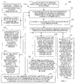
- FIG. 1 is a diagram of a method 100 for establishing a high speed wireless communication within an enterprise, according to an example embodiment.
- Some aspects of the method 100 are implemented as instructions residing on a computer-readable storage medium and executed by a plurality of processors.
- the processors are specifically configured to process certain aspects of the method 100.
- the method 100 forms and establishes a high speed wireless communication network within an enterprise.
- a plurality of wireless radios are physically situated in a grid layout within an enterprise.
- the grid is organized as a rectangle with each wireless radio geographically situated 10 meters (about 30 feet) apart from that wireless radio's nearest neighbouring wireless radio. So, no wireless radio is within 10 meters of another wireless radio.
- This configuration is designed to avoid interference and to ensure that each wireless radio is still within range of another wireless radio within the grid. It is noted that a rectangle arrangement may not always be possible at any given facility; in such a case, other arrangements of the grid can be configured providing interference is minimized and each wireless radio is still within contact of a next wireless radio to relay and transfer signals within the grid.
- each wireless radio is configured to use four transmission frequencies (F1-F4).
- Each wireless frequency transmits at 60 Gigahertz (GHz) using directional steerable antennas.
- the wireless data transmission rate can be up to 7 Gigabits per second (Gbs).
- Most wireless networks are only capable of 54 Megabits per second (Mbs).
- the 7 Gbs transmission rate is a 129 fold increase over the 54 Mbs. It is readily apparent that this huge increase in data transmission can provide a plethora of opportunities.
- At 121 at least one of the wireless radios is interfaced to a back-end wireless information server.
- the enterprise server can be connected to the Internet or connected over a Wide Area Network (WAN) to a geographically remote enterprise facility.
- WAN Wide Area Network
- the enterprise server can also be connected to private networks, such as a satellite link as an interconnection mechanism to distribute content (e.g., movie updates, etc.) to a lot of locations simultaneously. So, the enterprise server provides connectivity from the wireless radios to the data warehouse and resources of the enterprise and to outside networks (public and/or private).
- each antenna is configured to be remotely and wirelessly moved or repositioned by at least 45 degrees in two directions (90 degrees total). This permits the directional antennas to be focused on wireless devices of consumers positioned at locations within the enterprise because the 60 GHz is achieved via a directed beam for a limited distance (such as the 10 meters discussed above). Therefore, each antenna can be moved to focus on locations within a span of 90 degrees (45 degrees in two directions). Software instructions can also be processed on the wireless routers to automatically move the antennas. This includes antenna beam steering mechanisms as well.
- a demand reservation scheduling protocol can be installed and initiated on each or selective ones of the wireless radios. This allows for a guarantee of bandwidth for a particular transaction for a particular customer having a wireless device within the enterprise. This is discussed in greater detail below with reference to the FIG. 4 .
- At 130 at least one antenna for a particular wireless radio is positioned on each side of the wireless radio (see the FIGS. 4 and 5 below for a visual depiction of this arrangement).
- the wireless radios have 4 sides and each side has at least one directional steerable antenna.
- all or at least one of the wireless radios have one additional antenna on each side of the wireless radios. So, each side of the wireless radios has 2 directional steerable antennas. One antenna is used for transmission at one of the designated frequencies and another of the antennas is used for receiving data at that designated frequency. This permits full duplex communication along each of the four sides of the wireless radios (see the FIG. 4 and related discussion below). Separation can be achieved via an antenna pattern and the antennas' locations. Additional separation to reduce crosstalk between transmit and receive antennas can be achieved by using polarization, either circular or linear.
- each wireless radio is enabled to provide a wireless high speed communication network within the enterprise. That is, the wireless radios are configured to interface with one another, relaying signals along paths through the network so a consumer with a wireless device can access resources, information, and content within the wireless network beyond the 10 meter limit of any particular wireless device transmitting at 60 GHz.
- At 141 at least one of the wireless radios and one of its antennas at a particular one of the four frequencies is directed within 10 meters and in direct line of sight of a multimedia kiosk within the enterprise.
- the multimedia kiosk initiates wireless delivery of multimedia from a media source or media server accessible to the wireless network over the grid using the wireless router in line of sight; the delivery is directed via an antenna at a particular frequency to storage of a portable device that is in possession of a consumer within the enterprise.
- the consumer interacts with the multimedia kiosk to purchase multimedia, such as movies, music, etc.
- At 142 at least one of the wireless radios is directed and interfaced to a predefined position within the enterprise.
- video is wirelessly streamed from the wireless radio (via an antenna at a particular frequency) to a portable device of the consumer for playing the video on the portable device of the consumer.
- directed videos can be obtained by the consumer, via the portable device (such as a phone), when the consumer is in a predefined location within the enterprise, such as while in the electronics department where a video plays advertisements for a particular product the enterprise is pitching.
- wireless devices of a consumer within the enterprise are permitted to wireless connect to the high speed communication network while a portable device of the consumer remains within range of the high speed communication network.
- consumers can connect to and utilize the resources (made available by enterprise policy) of the high speed communication network using the consumers' portable devices (phones, netbooks, laptops, iPod Touch®, and the like).
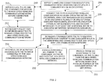
- FIG. 2 is a flow diagram illustrating another method 200 for operating a high speed wireless communication within an enterprise, according to an example embodiment.
- the method 200 (hereinafter “high speed wireless service”) is implemented as instructions within a computer-readable storage medium that execute on a plurality of processors, the processors specifically configured to execute the high speed wireless service.
- the high speed wireless service forms and provides a high speed wireless communication network within an enterprise.
- the high speed wireless service represents operational characteristics of the high speed wireless communication network established by the method 100, presented above with respect to the discussion of the FIG. 1 embodiment.
- high speed wireless service detects a wireless connection request originating from a portable device of a consumer within an enterprise.
- the high speed wireless service authenticates the portable device and the consumer for access to the high speed wireless communication network before the connection occurs to the network.
- the high speed wireless service sets a security policy that is enforced while the portable device remains connected to the high speed wireless communication network. So, automated security can be enforced to ensure that some consumers with a higher security clearance can utilize more resources than other consumers with lower security clearance. For instance, different levels of enterprise loyalty can permit different access to resources within the network.
- the high speed wireless service connects the portable device to the high speed wireless communication network.
- the high speed wireless communication network operates at 60 GHz using a plurality of grid situated wireless radios. Each wireless radio utilizing four different frequencies and each wireless radio interfaced to at least one additional wireless radio or to a back-end enterprise information server. This configuration was described in detail above with reference to the FIG. 1 and is described in greater detail below with reference to the FIGS. 4-5 .
- the high speed wireless service wirelessly transacts with the portable device to deliver information or content to the consumer while in the enterprise and connected to the high speed wireless communication network.
- the high speed wireless service records a log of activities occuring with the portable device while connected to the high speed wireless communication network.
- the activities within the log can also be dynamically evaluated so that should a consumer be performing suspicious activity as compared to policy or templates for detecting suspicious activity, that consumer can be disconnected automatically from the network.
- the log can also later be mined to see how consumers are using the resources of the network to improve the network or to see how a particular consumer is using the network to enhance each consumer's experience with the network during subsequent visits to the enterprise. So, this log of activities can be used by the enterprise in marketing campaigns or for other customer relationship management activities.
- the high speed wireless service provides purchased multimedia to the consumer, via the portable device and over the high speed wireless communication network. Examples of this were provided above with reference to the FIG. 1 .
- the high speed wireless service provides targeted advertising to the consumer, via the portable device and over the high speed wireless communication network based on a physical position of the consumer within the enterprise. Again, this situation was also presented above with reference to the FIG. 1 .
- FIG. 3 is a diagram of an enterprise high speed wireless communication system 300, according to an example embodiment.
- the enterprise high speed wireless communication system 300 is implemented as instructions residing in computer-readable storage media and to execute a plurality of processors (embedded in network devices (routers, switches, hubs, etc.) to collectively form a high speed wireless network within an enterprise.
- processors embedded in network devices (routers, switches, hubs, etc.) to collectively form a high speed wireless network within an enterprise.
- the enterprise high speed wireless communication system 300 implements, inter alia, the methods 100 and 200 of FIGS. 1 and 2 , respectively.
- the enterprise high speed wireless communication system 300 includes a back-end information server 301 and a plurality of wireless routers 302. Each of these and their interactions with one another will now be discussed in turn.
- the back-end information server 301 is configured to receive data from the wireless routers 302 and to deliver data to the wireless routers 302.
- the back-end information server 301 is configured to access the Internet and provide content from the Internet to the high speed wireless communication network (discussed below).
- the back-end information server 301 is also configured to deliver information from the high speed wireless communication network to services located remote from the enterprise over the Internet.
- the wireless routers 302 are arranged in a grid layout throughout an enterprise. Aspects of the configuration of the wireless routers 302 were presented above with reference to the FIG. 1 . Also, processing features of the wireless routers when operational to form a high speed wireless communication network were presented in detail above with reference to the FIG. 2 .
- Each wireless router 302 is configured to wirelessly receive and wirelessly transmit data within the enterprise over the grid at 60 GHz. Moreover, each wireless router 302 is further configured to interact with at least one additional wireless router 302 and each wireless router 302 configured to interact with wireless devices of consumers within the enterprise.
- the back-end information server 301 and the wireless routers 302 are configured and interfaced to one another to provide the high speed wireless communication network within the enterprise to the wireless devices of the consumers.
- each wireless router 302 is configured with four pairs of directional steerable antennas.
- Each pair of the directional steerable antennas is situated on one side of the particular wireless router to which that pair is related (see the FIG. 4 and related discussion and the above discussion associated with the FIG. 1 ).
- One antenna of a pair is used for data transmission and the other antenna of the pair is used for data reception permitting full wireless duplex communication on each side of a wireless radio 302 at one of four frequencies transmitting and receiving at 60 GHz.
- each wireless router 302 is situated within the grid layout at 10 meters from a next and neighboring wireless router. This minimizes interference and ensures that communication paths can be achieved through the high speed wireless communication network.
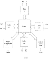
- FIG. 4 is a diagram of a sample enterprise high speed wireless architecture for a wireless router, according to an example embodiment. It is noted that the architecture presented is provided as an illustration and that other configurations are possible with additional components (devices and connections) or fewer components or even components in a different layout. These alternative arrangements are intended to fall within the scope of the present teachings when arranged to perform the techniques presented herein.
- Wireless communications has continuously increased in data transmission rates in recent years. Specifically, over the last few years technology has progressed to open up the 60 GHz (Gigahertz) ISM (Industrial Scientific and Medial radio bands) frequency band.
- 60 GHz Gigahertz
- ISM Intelligent Scientific and Medial radio bands
- ECMA-387 European Computing Manufacturers Association
- PAN Personal Area Networks
- ECMA-387 European Computing Manufacturers Association
- class A service is intended for high speed point to point communications, providing multi-gigabit data rates, using directional steerable (beam steering) antennas.
- the communications logic in these units is essentially a router or switch architecture and can be either connection or packet communications oriented.
- Any particular device receives high speed data on one of its high speed communications links, on for instance frequency 1 (F1), and routes the data with minimal buffering to one of the other ports (antennas) directed another router/switch unit at another frequency (F2) or downward to another end unit, in this case a DVD kiosk at yet another frequency (F3).
- F1 frequency 1
- F2 router/switch unit
- F3 yet another frequency
- these routers implement a demand reservation type scheduling protocol for communications that requires consistent delays, for instance audio and video streams for direct consumption by a customer or consumer of the enterprise.
- Demand reservation implies that a certain traffic capacity (bandwidth) is reserved in the communication's stream for the duration of the connection to guarantee a certain level of quality in terms of overall delay, delay variation, and/or error rate, which translates into glitches, noise and pixelization in video streams.
- bandwidth bandwidth
- demand reservation guarantees that the data is transferred with minimum delay to result in an acceptable transaction time for the consumer that is checking out a video.
- the kiosk is designed to provide high speed wireless video download to a device (memory stick, cell phone, etc.) of the consumer.
- the highly directive nature of the wireless communications antennas at 60 GHz allows the use of very small beam steering antennas. This enables re-use of the same frequency in the same device if antennas are pointed in different directions without that the signals interfering with each other. It is even possible to use the same frequency at separate transmit and receive antennas pointing at another device and transmit and receive two separate data streams simultaneously, i.e. implement full duplex communications.
- a standard 802.11 unit can be added as an interface to existing retail or consumer devices such as a cell phone equipped with WiFi (wireless communications).
- This can be initiated by consumer action such as taking a picture of a product, barcode or advertising display and be driven by a web application hosted on the store (enterprise) infrastructure.
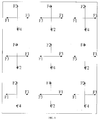
- FIG. 5 is a diagram of a sample transmission configuration for an enterprise high speed wireless communication network, according to an example embodiment.
- FIG. 5 presents a layout grid for transmission devices within an enterprise to provide optimal high speed wireless communication. It is noted that other layouts are foreseeable and can be achieved without departing from the teachings provided herein when such arrangements perform the techniques provided herein.
- FIG. 5 is discussed in terms of the sample layout and sample scenarios that are not intended to limit the other aspects of the teachings presented herein and above.
- the grid can be arranged as a hexagonal grid layout, rather than the rectangle layout depicted in the FIG. 5 .
- a hexagonal layout just 3 frequencies are needed.
- a large store or infrastructure can be set up using multiple devices re-using the same frequency.
- FIG. 5 shows an example of an infrastructure (section) with re-use of the frequencies alternation between rows and columns.
- the distance between the rows and columns is highly dependant on the actual radio and antenna designs.
- the ECMA standard promises a distance of 10 meters, about 30 feet. It should be straight forward to extend this with improved antenna designs.
- Directive steerable antennas provide enough distance and separation between radios to allow re-use. For instance the F2 used vertically in ceiling unit in position 1,1 (bottom left) is aimed at the receiver at position 2,1 (middle left). Due to the line of sight communications and highly directive nature of the antennas the only interfering transmitters for the receiver at 1,1 are towards the top of the diagram in column 1. In FIG. 5 this would be position 4,1 (outside FIG. 5 ).
- This interfering transmitter is located at 3 times the distance of the intended transmitter, which results in a theoretical signal to interference ratio of about 10 dB, sufficient for good communications quality provided the proper encoding and error correction is used.
- the interference can be further reduced, such that the first interfering transmitter is in position 6,1 at 5 times the distance resulting in a signal to interference ratio of about 15 db.
- the building layout may not allow for a neat rectangular layout in all parts of the building.
- the layout example in FIG. 5 is a simple rectangular layout.
- the antenna design is intended such that the antenna directivity is electronically steerable over an angle of at least 90 (+/-45) degrees. This means that more complex layouts are easily implemented provided that potential interference is accounted for.
- the antenna directivity limits the angle over which the interference is a potential problem and simplifies layout.
- the best route can be chosen based on momentary traffic conditions. It also allows for redundancy in case of failure of a device.
- the techniques and systems presented herein provide for a high speed wireless infrastructure suitable for transfer of large data volumes from a server to an end device such as DVD content to a kiosk, and the like.
- the provided techniques and systems provide for an infrastructure with a high degree of scalability for multiple applications that require a high aggregate throughput such as many customers in a store accessing information about products on the shelf of the store (enterprise).
Landscapes
- Engineering & Computer Science (AREA)
- Computer Networks & Wireless Communication (AREA)
- Signal Processing (AREA)
- Mobile Radio Communication Systems (AREA)
Claims (14)
- Verfahren zum Bereitstellen eines drahtlosen Kommunikationssystems, die folgenden Schritte umfassend:Anordnen einer Vielzahl von drahtlosen Funkgeräten (302) in einer Rasteranordnung innerhalb eines Unternehmens; Konfigurieren jedes drahtlosen Funkgeräts (302) zur Verwendung von vier Übertragungsfrequenzen, wobei jede einzelne Frequenz zum drahtlosen Empfangen und Übertragen bei 60 Gigahertz (GHz) unter Einsatz steuerbarer Richtantennen verwendet wird;Anordnen mindestens einer steuerbaren Richtantenne für ein bestimmtes drahtloses Funkgerät (302) auf jeder Seite jedes drahtlosen Funkgeräts (302); undAktivieren der drahtlosen Funkgeräte (302) zum Bereitstellen eines drahtlosen Hochgeschwindigkeitskommunikationsnetzwerks innerhalb des Unternehmens.
- Verfahren nach Anspruch 1, worin der Schritt des Anordnens einer Vielzahl von drahtlosen Funkgeräten (302) des Weiteren das Organisieren des Rasters als Rechteck beinhaltet, wobei sich jedes drahtlose Funkgerät (302) in einem Abstand von 10 Metern von einem nächstgelegenen benachbarten drahtlosen Funkgerät (302) befindet.
- Verfahren nach Anspruch 1 oder 2, worin der Schritt des Konfigurierens jedes drahtlosen Funkgeräts (302) des Weiteren das Verbinden von mindestens einem der drahtlosen Funkgeräte (302) mit einem Unternehmensinformationsserver (301) beinhaltet.
- Verfahren nach einem der Ansprüche 1 bis 3, worin der Schritt des Konfigurierens jedes drahtlosen Funkgeräts (302) des Weiteren das Konfigurieren jeder steuerbaren Richtantenne beinhaltet, sodass diese ferngesteuert und drahtlos für eine ferngesteuerte Gesamtbewegung von 90 Grad um mindestens 45 Grad in zwei unterschiedliche Richtungen bewegbar oder repositionierbar sind.
- Verfahren nach einem der Ansprüche 1 bis 4, worin der Schritt des Konfigurierens jedes drahtlosen Funkgeräts (302) des Weiteren das Installieren und Einleiten eines Anforderungs-Reservierungs-Planungsprotokolls in jedem drahtlosen Funkgerät (302) beinhaltet, was eine Garantie auf Bandbreite für Transaktionen erlaubt, die das Anforderungs-Reservierungs-Planungsprotokoll verwenden.
- Verfahren nach einem der Ansprüche 1 bis 5, worin der Schritt der Anordnung mindestens einer steuerbaren Richtantenne des Weiteren das Bereitstellen mindestens einer zusätzlichen steuerbaren Richtantenne auf jeder Seite jedes drahtlosen Funkgeräts (302) beinhaltet, wobei eine steuerbare Richtantenne für das Übertragen von Daten reserviert ist, und eine steuerbare Richtantenne für das Empfangen der Daten reserviert ist, wobei jede Frequenz der vier Frequenzen für jedes drahtlose Funkgerät (302) für drahtlose Vollduplex-Kommunikationen konfiguriert ist.
- Verfahren nach einem der Ansprüche 1 bis 6, worin der Schritt des Aktivierens jedes drahtlosen Funkgeräts (302) des Weiteren das Verbinden mindestens eines drahtlosen Funkgeräts (302) beinhaltet, das innerhalb von 10 Metern in direkter Sichtverbindung eines Multimedia-Kiosks auszurichten ist, wobei der Multimedia-Kiosk drahtlose Übertragung von Multimedia von einer Medienquelle über das Raster an das mindestens eine drahtlose Funkgerät (302) einleitet, und wobei die Multimedia drahtlos dem Speicher einer tragbaren Vorrichtung eines Verbrauchers innerhalb eines Unternehmens als Reaktion auf den mit dem Multimedia-Kiosk interagierenden Verbraucher bereitgestellt werden.
- Verfahren nach einem der vorstehenden Ansprüche, worin der Schritt des Aktivierens (302) des Weiteren das Verbinden von mindestens einem drahtlosen Funkgerät (302) beinhaltet, das in einer vordefinierte Position innerhalb des Unternehmens ausgerichtet werden soll, und in dieser Position drahtlos Videos von mindestens einem drahtlosen Funkgerät (302) an eine tragbare Vorrichtung eines Verbrauchers zum Abspielen des Videos auf der tragbaren Vorrichtung streamt.
- Verfahren nach einem der vorstehenden Ansprüche, worin der Schritt des Aktivierens jedes drahtlosen Funkgeräts (302) des Weiteren beinhaltet, dass es den tragbaren Vorrichtungen eines Verbrauchers innerhalb des Unternehmens ermöglicht wird, sich drahtlos mit dem Hochgeschwindigkeitskommunikationsnetzwerk zu verbinden, während eine tragbare Vorrichtung des Verbrauchers in Reichweite des Hochgeschwindigkeitskommunikationsnetzwerks bleibt.
- System (300) für drahtlose Kommunikation, Folgendes umfassend:ein innerhalb eines Unternehmens angeordneter Back-End-Informationsserver (301); undeine Vielzahl von drahtlosen Routern (302), die im gesamten Unternehmen in einer Rasteranordnung angeordnet sind;wobei der Back-End-Informationsserver (301) so konfiguriert ist, dass er Daten von den drahtlosen Routern (302) empfängt und Daten an die drahtlosen Router (302) liefert, und wobei jeder drahtlose Router (302) so konfiguriert ist, dass er die Daten innerhalb des Unternehmens und über die Rasteranordnung unter Verwendung von vier Übertragungsfrequenzen bei 60 Gigahertz (GHz) und dem Einsatz steuerbarer Richtantennen drahtlos empfängt und drahtlos überträgt, und jeder einzelne drahtlose Router (302) ist des Weiteren konfiguriert mit mindestens einer steuerbaren Richtantenne für einen bestimmten drahtlosen Router (302), die auf jeder Seite jedes drahtlosen Routers (302) anordnet ist, und jeder einzelne drahtlose Router (302) ist des Weiteren so konfiguriert, dass er mit mindestens einem zusätzlichen drahtlosen Router (302) interagiert, und jeder drahtlose Router (302) ist so konfiguriert, dass er mit tragbaren Vorrichtungen des Verbrauchers innerhalb des Unternehmens, dem Back-End-Informationsserver (301) und den drahtlosen Routern (302) interagiert, die so konfiguriert sind, dass sie den tragbaren Vorrichtungen der Verbrauchers ein drahtloses Hochgeschwindigkeitsnetzwerk innerhalb des Unternehmens bereitstellen.
- System nach Anspruch 10, worin der Back-End-Informationsserver (301) für den Zugriff auf das Internet konfiguriert ist, um dem drahtlosen Hochgeschwindigkeitskommunikationsnetzwerk Inhalt aus dem Internet bereitzustellen und über das Internet Informationen vom drahtlosen Hochgeschwindigkeitskommunikationsnetzwerk an vom Unternehmen entfernt angeordnete Dienste zu liefern.
- System nach Anspruch 10 oder 11, worin jeder drahtlose Router (302) zum drahtlosen Vollduplex-Übertragen und -Empfangen über vier separate Frequenzen konfiguriert ist.
- System nach einem der Ansprüche 10 bis 12, worin jeder einzelne drahtlose Router (302) mit vier Paaren steuerbarer Richtantennen konfiguriert ist, wobei jedes Paar der steuerbaren Richtantennen auf einer Seite des bestimmten drahtlosen Routers (302) angeordnet ist, auf den sich dieses Paar bezieht.
- System nach einem der Ansprüche 10 bis 13, worin sich jeder drahtlose Router (302) innerhalb der Rasteranordnung in einem Abstand von zehn Metern von einem nächsten und benachbarten drahtlosen Router (302) befindet.
Applications Claiming Priority (1)
| Application Number | Priority Date | Filing Date | Title |
|---|---|---|---|
| US12/655,265 US8345577B2 (en) | 2009-12-28 | 2009-12-28 | High speed wireless infrastructure |
Publications (2)
| Publication Number | Publication Date |
|---|---|
| EP2339878A1 EP2339878A1 (de) | 2011-06-29 |
| EP2339878B1 true EP2339878B1 (de) | 2016-09-21 |
Family
ID=43743562
Family Applications (1)
| Application Number | Title | Priority Date | Filing Date |
|---|---|---|---|
| EP10193642.5A Active EP2339878B1 (de) | 2009-12-28 | 2010-12-03 | Drahtlose Hochgeschwindigkeitsinfrastruktur mit drahtlosen Radios, welche gemäß einer Gitterauslegung platziert sind und richtungsänderbaren Antennen verwenden |
Country Status (3)
| Country | Link |
|---|---|
| US (1) | US8345577B2 (de) |
| EP (1) | EP2339878B1 (de) |
| JP (1) | JP5704866B2 (de) |
Families Citing this family (5)
| Publication number | Priority date | Publication date | Assignee | Title |
|---|---|---|---|---|
| US10715579B2 (en) * | 2011-08-31 | 2020-07-14 | Ncr Corporation | Methods and apparatus for downloading digital content |
| EP2752068A4 (de) * | 2011-09-01 | 2015-08-05 | Nec Corp | Kommunikationsendgerät, kommunikationsverfahren, kommunikationssystem und programm |
| US9538138B2 (en) | 2013-06-05 | 2017-01-03 | Puddle Innovations | System for providing access to shared multimedia content |
| CN107995683B (zh) * | 2017-12-13 | 2021-01-26 | 北京小米移动软件有限公司 | 定位系统、室内定位方法、服务器及存储介质 |
| US11570233B2 (en) * | 2018-07-31 | 2023-01-31 | Vestel Elektronik Sanayi Ve Ticaret A.S. | Method, apparatus, system and computer program for data distribution |
Family Cites Families (17)
| Publication number | Priority date | Publication date | Assignee | Title |
|---|---|---|---|---|
| US5488737A (en) * | 1992-11-17 | 1996-01-30 | Southwestern Bell Technology Resources, Inc. | Land-based wireless communications system having a scanned directional antenna |
| ATE429084T1 (de) * | 1999-07-20 | 2009-05-15 | Texas Instruments Inc | Drahtloses netzwerk mit kalibrierung von steuerbaren antennen über unabhängigen kontrollpfad |
| JP2001169342A (ja) * | 1999-12-10 | 2001-06-22 | Hitachi Kokusai Electric Inc | 無線アクセスシステム |
| JP3747759B2 (ja) * | 2000-09-20 | 2006-02-22 | 日本ビクター株式会社 | 情報配信システム |
| JP4489935B2 (ja) * | 2000-12-08 | 2010-06-23 | 株式会社日立国際電気 | 無線通信システム |
| US20040078209A1 (en) * | 2002-10-22 | 2004-04-22 | Thomson Rodney A. | Method and apparatus for on-site enterprise associate and consumer matching |
| JP2004349799A (ja) * | 2003-05-20 | 2004-12-09 | Nippon Telegr & Teleph Corp <Ntt> | 無線通信装置、無線通信システム、基地局 |
| US7587173B2 (en) * | 2003-06-19 | 2009-09-08 | Interdigital Technology Corporation | Antenna steering for an access point based upon spatial diversity |
| US7734293B2 (en) * | 2003-10-29 | 2010-06-08 | Martin Zilliacus | Mapping wireless proximity identificator to subscriber identity for hotspot based wireless services for mobile terminals |
| US7532861B2 (en) * | 2004-12-23 | 2009-05-12 | Microsoft Corporation | Connection interface for conveying RF, data, and power between electronic devices |
| JP2006245827A (ja) * | 2005-03-01 | 2006-09-14 | Bb Mobile Corp | 無線通信システム及びセル構成方法 |
| US7483409B2 (en) * | 2005-12-30 | 2009-01-27 | Motorola, Inc. | Wireless router assisted security handoff (WRASH) in a multi-hop wireless network |
| US20070201540A1 (en) * | 2006-02-14 | 2007-08-30 | Berkman William H | Hybrid power line wireless communication network |
| WO2008011376A2 (en) * | 2006-07-21 | 2008-01-24 | General Electric Company | System and method for providing network device authentication |
| US9300923B2 (en) * | 2007-03-26 | 2016-03-29 | Pelco, Inc. | Method and apparatus for improving video performance in a wireless surveillance system |
| US8041333B2 (en) * | 2007-06-14 | 2011-10-18 | Broadcom Corporation | Method and system for 60 GHz antenna adaptation and user coordination based on base station beacons |
| US8850204B2 (en) * | 2009-12-23 | 2014-09-30 | Intel Corporation | Multi-band/multi-link secure key generation and delivery protocol |
-
2009
- 2009-12-28 US US12/655,265 patent/US8345577B2/en active Active
-
2010
- 2010-09-02 JP JP2010196355A patent/JP5704866B2/ja active Active
- 2010-12-03 EP EP10193642.5A patent/EP2339878B1/de active Active
Non-Patent Citations (1)
| Title |
|---|
| None * |
Also Published As
| Publication number | Publication date |
|---|---|
| US20110158126A1 (en) | 2011-06-30 |
| JP5704866B2 (ja) | 2015-04-22 |
| US8345577B2 (en) | 2013-01-01 |
| JP2011139430A (ja) | 2011-07-14 |
| EP2339878A1 (de) | 2011-06-29 |
Similar Documents
| Publication | Publication Date | Title |
|---|---|---|
| JP6553263B2 (ja) | 非基本モード伝搬を用いる導波送信デバイス及びそれとともに使用するための方法 | |
| JP6862571B2 (ja) | 非リアルタイムコンテンツ配信サービスを提供するための方法およびシステム | |
| US10098011B2 (en) | Surface-wave communications and methods thereof | |
| US20190028760A1 (en) | Method and system for efficient communication | |
| EP2339878B1 (de) | Drahtlose Hochgeschwindigkeitsinfrastruktur mit drahtlosen Radios, welche gemäß einer Gitterauslegung platziert sind und richtungsänderbaren Antennen verwenden | |
| KR101541676B1 (ko) | 근접성-기반 콘텐츠 동기화를 갖는 휴대용 전자 장치 | |
| CN105594138B (zh) | 远程分布式天线系统 | |
| JP6878419B2 (ja) | 通信システム、導波スイッチ、及びそれらの使用方法 | |
| US20190140746A1 (en) | Quasi-optical coupler | |
| Benkler | Open wireless vs. licensed spectrum: Evidence from market adoption | |
| US12232197B2 (en) | Systems and methods for improving wireless mesh networks | |
| KR20170036777A (ko) | 유도파 커플러들 및 그의 방법들 | |
| KR20140097250A (ko) | 후속 검토를 위해 관심 있는 컨텐츠의 상기를 가능하게 하는 방법, 장치 및 시스템 | |
| Sacco | The evolution of the telecom infrastructure business: unchartered waters ahead of great opportunities | |
| US10447378B1 (en) | Wireless mesh network for broadband connectivity | |
| US20190182755A1 (en) | Virtual private network | |
| Cosmas et al. | 5G Internet of radio light services for supermarkets | |
| US8837361B2 (en) | System and method for access over a cable television network | |
| Peters et al. | The bats project | |
| KR102424247B1 (ko) | 배달 메뉴 공유 플랫폼 | |
| US7058355B2 (en) | Propagation of a wireless network through commercial outlets | |
| WO2023150133A1 (en) | Systems and methods for improving wireless mesh networks | |
| Sharif | Shereen Ali Malek Ahmed B. Sc in Electrical Engineering Honor, 2004 |
Legal Events
| Date | Code | Title | Description |
|---|---|---|---|
| PUAI | Public reference made under article 153(3) epc to a published international application that has entered the european phase |
Free format text: ORIGINAL CODE: 0009012 |
|
| AK | Designated contracting states |
Kind code of ref document: A1 Designated state(s): AL AT BE BG CH CY CZ DE DK EE ES FI FR GB GR HR HU IE IS IT LI LT LU LV MC MK MT NL NO PL PT RO RS SE SI SK SM TR |
|
| AX | Request for extension of the european patent |
Extension state: BA ME |
|
| 17P | Request for examination filed |
Effective date: 20111229 |
|
| 17Q | First examination report despatched |
Effective date: 20151022 |
|
| RIC1 | Information provided on ipc code assigned before grant |
Ipc: H04W 16/28 20090101AFI20160608BHEP Ipc: H04W 84/10 20090101ALN20160608BHEP |
|
| GRAP | Despatch of communication of intention to grant a patent |
Free format text: ORIGINAL CODE: EPIDOSNIGR1 |
|
| INTG | Intention to grant announced |
Effective date: 20160715 |
|
| RIC1 | Information provided on ipc code assigned before grant |
Ipc: H04W 84/10 20090101ALN20160701BHEP Ipc: H04W 16/28 20090101AFI20160701BHEP |
|
| GRAS | Grant fee paid |
Free format text: ORIGINAL CODE: EPIDOSNIGR3 |
|
| GRAA | (expected) grant |
Free format text: ORIGINAL CODE: 0009210 |
|
| AK | Designated contracting states |
Kind code of ref document: B1 Designated state(s): AL AT BE BG CH CY CZ DE DK EE ES FI FR GB GR HR HU IE IS IT LI LT LU LV MC MK MT NL NO PL PT RO RS SE SI SK SM TR |
|
| REG | Reference to a national code |
Ref country code: GB Ref legal event code: FG4D |
|
| REG | Reference to a national code |
Ref country code: CH Ref legal event code: EP |
|
| REG | Reference to a national code |
Ref country code: DE Ref legal event code: R084 Ref document number: 602010036543 Country of ref document: DE |
|
| REG | Reference to a national code |
Ref country code: AT Ref legal event code: REF Ref document number: 831909 Country of ref document: AT Kind code of ref document: T Effective date: 20161015 |
|
| REG | Reference to a national code |
Ref country code: IE Ref legal event code: FG4D |
|
| REG | Reference to a national code |
Ref country code: GB Ref legal event code: 746 Effective date: 20161013 |
|
| REG | Reference to a national code |
Ref country code: DE Ref legal event code: R096 Ref document number: 602010036543 Country of ref document: DE |
|
| REG | Reference to a national code |
Ref country code: FR Ref legal event code: PLFP Year of fee payment: 7 |
|
| REG | Reference to a national code |
Ref country code: LT Ref legal event code: MG4D Ref country code: NL Ref legal event code: MP Effective date: 20160921 |
|
| PG25 | Lapsed in a contracting state [announced via postgrant information from national office to epo] |
Ref country code: FI Free format text: LAPSE BECAUSE OF FAILURE TO SUBMIT A TRANSLATION OF THE DESCRIPTION OR TO PAY THE FEE WITHIN THE PRESCRIBED TIME-LIMIT Effective date: 20160921 Ref country code: LT Free format text: LAPSE BECAUSE OF FAILURE TO SUBMIT A TRANSLATION OF THE DESCRIPTION OR TO PAY THE FEE WITHIN THE PRESCRIBED TIME-LIMIT Effective date: 20160921 Ref country code: NO Free format text: LAPSE BECAUSE OF FAILURE TO SUBMIT A TRANSLATION OF THE DESCRIPTION OR TO PAY THE FEE WITHIN THE PRESCRIBED TIME-LIMIT Effective date: 20161221 Ref country code: RS Free format text: LAPSE BECAUSE OF FAILURE TO SUBMIT A TRANSLATION OF THE DESCRIPTION OR TO PAY THE FEE WITHIN THE PRESCRIBED TIME-LIMIT Effective date: 20160921 |
|
| REG | Reference to a national code |
Ref country code: AT Ref legal event code: MK05 Ref document number: 831909 Country of ref document: AT Kind code of ref document: T Effective date: 20160921 |
|
| PG25 | Lapsed in a contracting state [announced via postgrant information from national office to epo] |
Ref country code: NL Free format text: LAPSE BECAUSE OF FAILURE TO SUBMIT A TRANSLATION OF THE DESCRIPTION OR TO PAY THE FEE WITHIN THE PRESCRIBED TIME-LIMIT Effective date: 20160921 Ref country code: GR Free format text: LAPSE BECAUSE OF FAILURE TO SUBMIT A TRANSLATION OF THE DESCRIPTION OR TO PAY THE FEE WITHIN THE PRESCRIBED TIME-LIMIT Effective date: 20161222 Ref country code: SE Free format text: LAPSE BECAUSE OF FAILURE TO SUBMIT A TRANSLATION OF THE DESCRIPTION OR TO PAY THE FEE WITHIN THE PRESCRIBED TIME-LIMIT Effective date: 20160921 Ref country code: LV Free format text: LAPSE BECAUSE OF FAILURE TO SUBMIT A TRANSLATION OF THE DESCRIPTION OR TO PAY THE FEE WITHIN THE PRESCRIBED TIME-LIMIT Effective date: 20160921 |
|
| PG25 | Lapsed in a contracting state [announced via postgrant information from national office to epo] |
Ref country code: RO Free format text: LAPSE BECAUSE OF FAILURE TO SUBMIT A TRANSLATION OF THE DESCRIPTION OR TO PAY THE FEE WITHIN THE PRESCRIBED TIME-LIMIT Effective date: 20160921 Ref country code: EE Free format text: LAPSE BECAUSE OF FAILURE TO SUBMIT A TRANSLATION OF THE DESCRIPTION OR TO PAY THE FEE WITHIN THE PRESCRIBED TIME-LIMIT Effective date: 20160921 |
|
| PG25 | Lapsed in a contracting state [announced via postgrant information from national office to epo] |
Ref country code: BE Free format text: LAPSE BECAUSE OF FAILURE TO SUBMIT A TRANSLATION OF THE DESCRIPTION OR TO PAY THE FEE WITHIN THE PRESCRIBED TIME-LIMIT Effective date: 20160921 Ref country code: CZ Free format text: LAPSE BECAUSE OF FAILURE TO SUBMIT A TRANSLATION OF THE DESCRIPTION OR TO PAY THE FEE WITHIN THE PRESCRIBED TIME-LIMIT Effective date: 20160921 Ref country code: IS Free format text: LAPSE BECAUSE OF FAILURE TO SUBMIT A TRANSLATION OF THE DESCRIPTION OR TO PAY THE FEE WITHIN THE PRESCRIBED TIME-LIMIT Effective date: 20170121 Ref country code: PL Free format text: LAPSE BECAUSE OF FAILURE TO SUBMIT A TRANSLATION OF THE DESCRIPTION OR TO PAY THE FEE WITHIN THE PRESCRIBED TIME-LIMIT Effective date: 20160921 Ref country code: BG Free format text: LAPSE BECAUSE OF FAILURE TO SUBMIT A TRANSLATION OF THE DESCRIPTION OR TO PAY THE FEE WITHIN THE PRESCRIBED TIME-LIMIT Effective date: 20161221 Ref country code: SM Free format text: LAPSE BECAUSE OF FAILURE TO SUBMIT A TRANSLATION OF THE DESCRIPTION OR TO PAY THE FEE WITHIN THE PRESCRIBED TIME-LIMIT Effective date: 20160921 Ref country code: ES Free format text: LAPSE BECAUSE OF FAILURE TO SUBMIT A TRANSLATION OF THE DESCRIPTION OR TO PAY THE FEE WITHIN THE PRESCRIBED TIME-LIMIT Effective date: 20160921 Ref country code: AT Free format text: LAPSE BECAUSE OF FAILURE TO SUBMIT A TRANSLATION OF THE DESCRIPTION OR TO PAY THE FEE WITHIN THE PRESCRIBED TIME-LIMIT Effective date: 20160921 Ref country code: SK Free format text: LAPSE BECAUSE OF FAILURE TO SUBMIT A TRANSLATION OF THE DESCRIPTION OR TO PAY THE FEE WITHIN THE PRESCRIBED TIME-LIMIT Effective date: 20160921 Ref country code: PT Free format text: LAPSE BECAUSE OF FAILURE TO SUBMIT A TRANSLATION OF THE DESCRIPTION OR TO PAY THE FEE WITHIN THE PRESCRIBED TIME-LIMIT Effective date: 20170123 |
|
| REG | Reference to a national code |
Ref country code: DE Ref legal event code: R097 Ref document number: 602010036543 Country of ref document: DE |
|
| PG25 | Lapsed in a contracting state [announced via postgrant information from national office to epo] |
Ref country code: IT Free format text: LAPSE BECAUSE OF FAILURE TO SUBMIT A TRANSLATION OF THE DESCRIPTION OR TO PAY THE FEE WITHIN THE PRESCRIBED TIME-LIMIT Effective date: 20160921 |
|
| PLBE | No opposition filed within time limit |
Free format text: ORIGINAL CODE: 0009261 |
|
| STAA | Information on the status of an ep patent application or granted ep patent |
Free format text: STATUS: NO OPPOSITION FILED WITHIN TIME LIMIT |
|
| PG25 | Lapsed in a contracting state [announced via postgrant information from national office to epo] |
Ref country code: DK Free format text: LAPSE BECAUSE OF FAILURE TO SUBMIT A TRANSLATION OF THE DESCRIPTION OR TO PAY THE FEE WITHIN THE PRESCRIBED TIME-LIMIT Effective date: 20160921 |
|
| REG | Reference to a national code |
Ref country code: CH Ref legal event code: PL |
|
| 26N | No opposition filed |
Effective date: 20170622 |
|
| PG25 | Lapsed in a contracting state [announced via postgrant information from national office to epo] |
Ref country code: MC Free format text: LAPSE BECAUSE OF FAILURE TO SUBMIT A TRANSLATION OF THE DESCRIPTION OR TO PAY THE FEE WITHIN THE PRESCRIBED TIME-LIMIT Effective date: 20160921 |
|
| REG | Reference to a national code |
Ref country code: IE Ref legal event code: MM4A |
|
| PG25 | Lapsed in a contracting state [announced via postgrant information from national office to epo] |
Ref country code: CH Free format text: LAPSE BECAUSE OF NON-PAYMENT OF DUE FEES Effective date: 20161231 Ref country code: LI Free format text: LAPSE BECAUSE OF NON-PAYMENT OF DUE FEES Effective date: 20161231 Ref country code: LU Free format text: LAPSE BECAUSE OF NON-PAYMENT OF DUE FEES Effective date: 20161203 |
|
| PG25 | Lapsed in a contracting state [announced via postgrant information from national office to epo] |
Ref country code: SI Free format text: LAPSE BECAUSE OF FAILURE TO SUBMIT A TRANSLATION OF THE DESCRIPTION OR TO PAY THE FEE WITHIN THE PRESCRIBED TIME-LIMIT Effective date: 20160921 Ref country code: IE Free format text: LAPSE BECAUSE OF NON-PAYMENT OF DUE FEES Effective date: 20161203 |
|
| REG | Reference to a national code |
Ref country code: FR Ref legal event code: PLFP Year of fee payment: 8 |
|
| PG25 | Lapsed in a contracting state [announced via postgrant information from national office to epo] |
Ref country code: HU Free format text: LAPSE BECAUSE OF FAILURE TO SUBMIT A TRANSLATION OF THE DESCRIPTION OR TO PAY THE FEE WITHIN THE PRESCRIBED TIME-LIMIT; INVALID AB INITIO Effective date: 20101203 Ref country code: CY Free format text: LAPSE BECAUSE OF FAILURE TO SUBMIT A TRANSLATION OF THE DESCRIPTION OR TO PAY THE FEE WITHIN THE PRESCRIBED TIME-LIMIT Effective date: 20160921 |
|
| PG25 | Lapsed in a contracting state [announced via postgrant information from national office to epo] |
Ref country code: HR Free format text: LAPSE BECAUSE OF FAILURE TO SUBMIT A TRANSLATION OF THE DESCRIPTION OR TO PAY THE FEE WITHIN THE PRESCRIBED TIME-LIMIT Effective date: 20160921 Ref country code: MK Free format text: LAPSE BECAUSE OF FAILURE TO SUBMIT A TRANSLATION OF THE DESCRIPTION OR TO PAY THE FEE WITHIN THE PRESCRIBED TIME-LIMIT Effective date: 20160921 Ref country code: TR Free format text: LAPSE BECAUSE OF FAILURE TO SUBMIT A TRANSLATION OF THE DESCRIPTION OR TO PAY THE FEE WITHIN THE PRESCRIBED TIME-LIMIT Effective date: 20160921 |
|
| PG25 | Lapsed in a contracting state [announced via postgrant information from national office to epo] |
Ref country code: MT Free format text: LAPSE BECAUSE OF NON-PAYMENT OF DUE FEES Effective date: 20161203 |
|
| PG25 | Lapsed in a contracting state [announced via postgrant information from national office to epo] |
Ref country code: AL Free format text: LAPSE BECAUSE OF FAILURE TO SUBMIT A TRANSLATION OF THE DESCRIPTION OR TO PAY THE FEE WITHIN THE PRESCRIBED TIME-LIMIT Effective date: 20160921 |
|
| REG | Reference to a national code |
Ref country code: DE Ref legal event code: R081 Ref document number: 602010036543 Country of ref document: DE Owner name: NCR VOYIX CORP., ATLANTA, US Free format text: FORMER OWNER: NCR CORPORATION, DULUTH, GA., US Ref country code: DE Ref legal event code: R082 Ref document number: 602010036543 Country of ref document: DE Representative=s name: V. BEZOLD & PARTNER PATENTANWAELTE - PARTG MBB, DE Ref country code: DE Ref legal event code: R081 Ref document number: 602010036543 Country of ref document: DE Owner name: NCR CORPORATION, ATLANTA, US Free format text: FORMER OWNER: NCR CORPORATION, DULUTH, GA., US |
|
| P01 | Opt-out of the competence of the unified patent court (upc) registered |
Effective date: 20230507 |
|
| REG | Reference to a national code |
Ref country code: DE Ref legal event code: R081 Ref document number: 602010036543 Country of ref document: DE Owner name: NCR VOYIX CORP., ATLANTA, US Free format text: FORMER OWNER: NCR CORPORATION, ATLANTA, GA, US |
|
| PGFP | Annual fee paid to national office [announced via postgrant information from national office to epo] |
Ref country code: GB Payment date: 20251229 Year of fee payment: 16 |
|
| PGFP | Annual fee paid to national office [announced via postgrant information from national office to epo] |
Ref country code: FR Payment date: 20251226 Year of fee payment: 16 |
|
| PGFP | Annual fee paid to national office [announced via postgrant information from national office to epo] |
Ref country code: DE Payment date: 20251229 Year of fee payment: 16 |