EP2339692A1 - Antenna assembly for a tag reader and method of reading transmission data - Google Patents
Antenna assembly for a tag reader and method of reading transmission data Download PDFInfo
- Publication number
- EP2339692A1 EP2339692A1 EP10194979A EP10194979A EP2339692A1 EP 2339692 A1 EP2339692 A1 EP 2339692A1 EP 10194979 A EP10194979 A EP 10194979A EP 10194979 A EP10194979 A EP 10194979A EP 2339692 A1 EP2339692 A1 EP 2339692A1
- Authority
- EP
- European Patent Office
- Prior art keywords
- antenna
- tire
- stand
- convex
- assembly
- Prior art date
- Legal status (The legal status is an assumption and is not a legal conclusion. Google has not performed a legal analysis and makes no representation as to the accuracy of the status listed.)
- Granted
Links
Images




Classifications
-
- H—ELECTRICITY
- H01—ELECTRIC ELEMENTS
- H01Q—ANTENNAS, i.e. RADIO AERIALS
- H01Q1/00—Details of, or arrangements associated with, antennas
- H01Q1/12—Supports; Mounting means
- H01Q1/22—Supports; Mounting means by structural association with other equipment or articles
- H01Q1/2208—Supports; Mounting means by structural association with other equipment or articles associated with components used in interrogation type services, i.e. in systems for information exchange between an interrogator/reader and a tag/transponder, e.g. in Radio Frequency Identification [RFID] systems
- H01Q1/2216—Supports; Mounting means by structural association with other equipment or articles associated with components used in interrogation type services, i.e. in systems for information exchange between an interrogator/reader and a tag/transponder, e.g. in Radio Frequency Identification [RFID] systems used in interrogator/reader equipment
-
- G—PHYSICS
- G06—COMPUTING OR CALCULATING; COUNTING
- G06K—GRAPHICAL DATA READING; PRESENTATION OF DATA; RECORD CARRIERS; HANDLING RECORD CARRIERS
- G06K7/00—Methods or arrangements for sensing record carriers, e.g. for reading patterns
- G06K7/10—Methods or arrangements for sensing record carriers, e.g. for reading patterns by electromagnetic radiation, e.g. optical sensing; by corpuscular radiation
- G06K7/10009—Methods or arrangements for sensing record carriers, e.g. for reading patterns by electromagnetic radiation, e.g. optical sensing; by corpuscular radiation sensing by radiation using wavelengths larger than 0.1 mm, e.g. radio-waves or microwaves
- G06K7/10316—Methods or arrangements for sensing record carriers, e.g. for reading patterns by electromagnetic radiation, e.g. optical sensing; by corpuscular radiation sensing by radiation using wavelengths larger than 0.1 mm, e.g. radio-waves or microwaves using at least one antenna particularly designed for interrogating the wireless record carriers
-
- H—ELECTRICITY
- H01—ELECTRIC ELEMENTS
- H01Q—ANTENNAS, i.e. RADIO AERIALS
- H01Q1/00—Details of, or arrangements associated with, antennas
- H01Q1/12—Supports; Mounting means
- H01Q1/22—Supports; Mounting means by structural association with other equipment or articles
- H01Q1/2208—Supports; Mounting means by structural association with other equipment or articles associated with components used in interrogation type services, i.e. in systems for information exchange between an interrogator/reader and a tag/transponder, e.g. in Radio Frequency Identification [RFID] systems
- H01Q1/2241—Supports; Mounting means by structural association with other equipment or articles associated with components used in interrogation type services, i.e. in systems for information exchange between an interrogator/reader and a tag/transponder, e.g. in Radio Frequency Identification [RFID] systems used in or for vehicle tyres
Definitions
- the invention relates generally to RFID device readers and, more specifically, to an antenna assembly for a reader of RFID devices mounted to the wheel units of a vehicle, as well as to a method of reading tire mounted RFID devices within a read station.
- Radio frequency identification devices are useful in association with sundry product categories and have gained widespread commercial importance and acceptance. Such devices generally have memory storage capability for electronically storing product-specific information such as product history and a product identification number.
- the device further provides an integrated transmitter that transmits responsive to a prompt signal the stored data for receipt by a receiver antenna. For example, it is known to associate an RFID with a vehicle tire or wheel rim assembly in order to access tire, vehicle, and/or wheel related identification and history throughout the lifetime service of the product.
- the invention relates to an antenna assembly in accordance with claim 1 and to a method in accordance with claim 15.
- an antenna assembly receives a data transmission from an electronic transmitting device mounted to a tire mounted vehicle.
- the antenna assembly includes a stand having an upper convex surface positioned to intercept and engage a vehicle tire as the vehicle tire passes over the elevated surface. The height and contour of the convex surface slows the rotational rate of the vehicle tire, and the transmitting device mounted to the tire, to a preferred rotational read rate as the vehicle tire passes over the convex surface.
- One or more antenna members mount to the stand below the convex surface, each antenna having a directionally aimed antenna field for coupled receipt of a data transmission from the electronic transmitting device as the vehicle tire passes over the convex stand surface at the reduced rotational read rate.
- the transmitting device is mounted to the vehicle tire and rotates with the tire and movement of the tire over the elevated surface at the reduced rotational read rate serves to prolong a coupling between the transmitting device and the one or more antenna fields.
- the span of the convex stand upper surface is sufficient to require at least one revolution by the tire and the transmitting device for the tire to pass over the convex surface at the reduced rotational read rate.
- the directionally aimed antenna is tilted at an acute tilt angle toward an approach path of the vehicle tire to the stand elevated surface.
- the convex surface of the stand may include a leading inclined surface portion tilted in the same direction as the antenna.
- a directionally aimed second antenna may be mounted to the stand in another aspect of the invention, the second antenna creating a directionally aimed second antenna field operative to receive data transmission from the electronic transmitting device as the vehicle tire passes over a trailing portion of the convex stand surface at the reduced rotational rate.
- the first and the second antenna may be positioned on opposite sides of the stand at oppositely directed tilt angles.
- the antenna assembly may include an extension member positioned adjacent to the stand and including an upper convex extension surface of complementary concavity with the stand upper convex surface. The antenna is thereby positioned to the side of the tire and the transmitting device as the vehicle tire passes over the extension member upper surface for improved transmission coupling.
- the method of reading a data transmission from an electronic transmitting device mounted to a vehicle tire assembly includes: positioning a convex upper surface of a stand to intercept a vehicle tire of the vehicle tire assembly; establishing rotational engagement between the vehicle tire and the convex upper surface of the stand to slow the speed of the vehicle and reduce the rotational rate at which the vehicle tire rotates to a targeted reduced rotational read rate; and directing an antenna field from at least one antenna toward an approach path of the vehicle tire to the convex upper surface of the stand to receive data transmission from the electronic transmitting device as the vehicle tire passes over the stand upper surface at the reduced rotational read rate.
- the method includes directing a second antenna field from at least a second antenna toward an exit path of the vehicle tire from the upper surface of the stand to receive data transmission from the electronic transmitting device as the vehicle tire passes over the stand upper surface at the reduced rotational read rate.
- the method includes tilting the directionally aimed first and second antenna fields at an acute tilt angle within a range of 13 to 15 degrees or 9 to 19 degrees toward the approach and exit paths, respectively, of the vehicle tire relative to the stand upper surface.
- the first and second antenna fields may, in another aspect, be positioned to place the transmitting device into a continuously coupled relationship with at least one of the first and second antenna fields as the vehicle tire passes across the convex upper surface.
- the method includes mounting the transmitting device to the vehicle tire assembly to rotate with the tire; and configuring the height and concavity of the upper convex surface to operatively require the tire and the transmitting device to substantially complete at least one revolution at the targeted reduced rotational read rate as the tire passes over the upper convex surface span.
- FIGS. 1A and 1B a schematic of an antenna system 10 is shown including an antenna 12 positioned flat on a ground surface 14.
- the antenna 12 generates a field or beam pattern 16 for the purpose of receiving data transmission signals 20 from an approaching electronic device 18.
- Device 18 is of a type commercially available and used, such as a radio frequency identification (RFID) tag.
- RFID radio frequency identification
- the tag 18 may be mounted to a product that moves toward and away from a read station in which the antenna 12 and its generated beam pattern 16 is situated.
- the speed at which the tag 18 approaches and leaves the vicinity of the antenna 12 will affect the time interval in which the transmitted data 20 is received by the antenna field 16.
- the read range of the antenna 12 is increased and represented by the shaded region 17 of the field 16. A maximized read range will positively affect the coupling efficiency between the transmitted signal 20 and the antenna field 16 and serve to promote a complete and accurate data transmission as the tag approaches and leaves the vicinity of the antenna 12.
- FIG. 1B shows an alternative antenna position within a read station in which the antenna 12 is tilted toward the approach path of the tag 18. Tilting of the antenna 12 at an acute angle ⁇ with respect to the ground surface 14 will cause the beam pattern 16 to tilt at angle ⁇ toward the approach path (represented by data transmission 20) of the tag 18. The tilting of the field 16 toward the approach path of the tag 18 serves to enlarge the read field 17 as shown by the larger shaded region of FIG. 1B as compared with the shaded region of FIG. 1A . The read range of the antenna 12 is thus maximized by introducing a mechanical tilt at angle ⁇ .
- the enlargement of the read range 17 effected by mechanically tilting the antenna 12 improves the reliability of the system and ensures that transmitted data will be captured as the tag 18 moves through the read zone. With the mechanical tilt, more of the cross-sectional area of the antenna pattern 16 is available and improved transmission efficiency is gained.
- a tilted antenna system stand 22 is shown to include a stand freestanding base 24 supported by elongate support legs 26, 27, 28, and 29.
- the support legs affix to an underside of the base 24 along outer peripheral locations and for support of the base on a ground surface.
- the stand 22 is provided with a cover 30 having a convex profile that covers the top of the base 24.
- convex is meant in a general sense.
- the cover upper convex surface may be composed of adjoining flat surface segments or be continuously radiussed as shown.
- the base is formed of any suitably strong material such as plastic, and is configured having a protruding latch finger 32 and latch slot 33 spaced apart along each side of the stand.
- the finger 32 is shaped to interlock with the slot 33 of a like-configured unit to thereby chain multiple stands together in a series.
- the stand cover 30 is of convex sectional configuration, formed to include a forward inclined surface 34 extending to an apex or crown 36, and a rearward inclined surface 38 extending from the crown 36 to a rearward side of the stand.
- a matrix of cross-ribs 40 may be molded into the underside of the base 24 for adding strength to the structure.
- the cross-ribs 40 define a forward antenna receiving recess 42 with support notches 44 formed in ribs along the sides of the recess 42.
- a similarly configured rearward antenna receiving recess 46 is positioned between the cross-ribs 40 of the rearward portion of the base, likewise providing support notches 48 formed in ribs along the sides of the rearward recess 46.
- a forward antenna 50 is sized to fit within the forward recess 42, resting upon notches 44.
- a rearward antenna 52 is positioned within rearward recess 46 and rests upon the notches 48.
- the notches 44, 48 formed within the cross-ribs 40 form an angled seat within the recesses 42, 46 such that the antennae 50, 52 when positioned within the recesses are at an acute angle with respect to a vertical centerline of the stand 22.
- the antennae 50, 52 angle in opposite directions from the centerline at an acute angle ⁇ (see FIG. 1B ) which is preferably between 13 to 15 degrees, although angles of different magnitudes may be used respectively for the two antenna in order to create the antenna field desired.
- the cover 30 is formed of RF transparent material and serves to enclose the antennae 50, 52 in their angled position within the stand.
- Assembly posts 54, 56 mate within sockets formed in the cover to attach the cover to the ground surface 14 in FIGS 1A and 1B .
- the antennae 50, 52 are angled within the base 24 at the aforementioned acute angle which may be the same for each antenna or different, depending on the system objectives and requirements.
- the antennae 50, 52 In the assembled condition, the antennae 50, 52 generally reside beneath the inclined RF transparent surfaces 34, 36, respectively.
- the angle of inclination of the antennae 50, 52 and the surface portions 34, 36 may be the same or differ.
- the stand assembly 22 it will be appreciated, produces a speed bump when the stand is positioned to intercept the wheels of an oncoming vehicle.
- the tires of the vehicle are intended to ride up the forward surface 34, over the crest or apex 38, and down the rearward inclined surface 38.
- the slopes of inclined surfaces 34, 38 are designed to create a bump of desired severity so that a vehicle traveling over the stand 22 will be slowed to an objective read speed.
- the slope of the inclined surfaces 34, 36 may be more or less than the slope of the inclined antennae 50, 52 within the stand, depending on the degree of bump necessary to slow the oncoming vehicle to an objective read speed.
- FIGS. 4A and 4B illustrate the operation of the speed bump created by the stand 22 and the tilted antenna 50, 52 positioned within the stand as a vehicle tire 58 rides up, over, and down the stand surfaces 34, 36, 38.
- the tire 58 includes a sidewall 60 and mounts to a rim 62 in standard fashion.
- An RFID tag 64 is secured to the tire 58 by conventional means at a conventional location such as to the tire inner liner (not shown) defining the tire cavity. So positioned, the tag 64 rotates with the tire 58 at the same speed of rotation.
- An antenna beam pattern 68 from the forward antenna 50 is tilted toward the tire 58 approach path as the tire engages and rolls up the inclined surface 34 of the stand 22.
- the tilt of the antenna 50 within the stand 22 tilts the field 66 so as to allow the signal from the tag 64 access to more of the field cross-section as tag 64 rotates with the tire.
- the second, rearwardly mounted antenna 52 is likewise tilted within the stand in the opposite (rearward facing) direction from the forward (forward facing) tilted antenna 50.
- the field or beam pattern 66 is thus tilted to the rear by the generally same angle ⁇ as the forward beam pattern 68 from antenna 50 tilts forward. It is preferred, although not necessary, that the acute tilt angle ⁇ be within the range of 13 to 15 degrees or 9 to 19 degrees.
- the position of the antenna 50 relative to the antenna 52 is close enough such that the beam patterns 66, 68 overlap to a minimal extent and cover without a gap the area above the stand 22.
- the tag 64 mounted to the tire 58, will rotate over the surfaces 34, 36, 38 with the tire and complete a revolution with the tire 58 within the time interval required for the tire to move over a stand and/or multiple antenna component assemblies 70 as shown in FIGS 5 and 9 .
- data transmission by the tag will intersect the beam patterns 66, 68 of one or both of the antenna 50, 52. A reliable and complete transmission of data is thereby assured.
- the speed at which the tag 64 rotates with the tire 58 may be controlled by controlling the front to rear span and/or degree and/or extent of incline of the speed bump represented by surfaces 34, 36, and 38 of the stand 22.
- a higher angle of tilt of the forward and rearward surface or lengthening the surfaces 34, 36, and/or 38 raises the "bump" and will generally obligate the driver of the vehicle to slow down to a greater extent.
- This slows the rotational speed of the tire and tag 64 over the stand 22 and elongates the time period (read interval) during which the tag transmission may be communicated to the antenna patterns 66, 68.
- the tag 64 may be mounted to the inner liner of the sidewall of the tire 58 as explained. For such a mounting location, it may be beneficial to mount the antenna 50, 52 to a side of the tire 58 for improved coupling between the antenna beam pattern and the data transmission from the tag.
- a bridging unit 72 may be utilized in a three-component stand assembly 70 such as that shown in FIGS. 6, 7 , and 8 .
- the tire is intended to ride directly over the bridging unit upper convex surface.
- the bridging unit 72 is situated between two antenna assemblies of the type described previously.
- the center or bridging unit 72 includes a body 74 having cross-rib reinforcement 76 and a convex upper surface 78.
- a pair of elongate support legs 80, 82 affix to an underside of the body 74 and support the body on a ground surface.
- a socket 84 connects the body 74 to the ground surface 14 in FIGS. 1A and 1B .
- the cover provides the arched or convex outer surface 78 and includes a forward inclined surface 86 and a rearward inclined surface 88, separated by an apex region 87.
- the forward and rearward surfaces 86, 88 have an acute tilt angle generally the same as the forward and rearward surfaces of the cover 30 ( FIGS. 2 and 3 ) described previously.
- the bridging unit body 74 is formed to provide a latch finger 92 and a latch slot 90 along each longitudinal side that mate and interconnect with the latch 32 and latch slot 33 of the base 24. Accordingly, a three component series may be interconnected consisting of two antenna stands 22 on opposite side of a single bridging stand unit 72 as shown in FIG. 8 .
- the center or bridging unit surfaces 86, 88 are targeted by a vehicle operator and tire 58 rides up and over the center unit during a drive-through read operation.
- the incline of the surfaces 86, 88 complement the incline of surfaces 34, 38 of the antenna assembly 22.
- the two antenna assemblies 22 on opposite sides of the center unit 72 are to the side of the tire 58 and function to ensure that a complete and accurate data transmission between the tag 64 and the antenna 50, 52 will occur.
- the tilt of the antenna 50, 52 within each of the antenna assemblies 22 on opposite sides of the center unit 72 is generally the same, and it is preferred that the tilt angle be generally 13-15 degrees although more or less tilt may be employed if desired.
- the tag 64 rotates with the tire 58. It is desirable to slow the vehicle by means of the speed bump formed one or two antenna stand assemblies 22 and, if desired, bridging unit 72.
- a single antenna stand assembly may be employed if it is preferred that the tire ride directly over the convex surface of RFID transparent cover 30. If an adjacent position of the antenna 50 and/or 52 is desired, stand assembly 22 may be used with a bridging unit 72.
- the tire rides over the bridging unit 72 in such a configuration with the antenna members 50, 52 positioned to the side. It is preferable that the speed bump configuration slow the rotational rate of the vehicle tire 58 to a targeted reduced rotational read rate optimal for effecting reliable data transmission as the tire passes over the convex upper surface.
- the size, shape and height of the bump will be selected to induce the vehicle operator to lower the speed of the vehicle to achieve the targeted reduced rotational read rate speed.
- the span and degree of incline created by surfaces 34, 36, 38 or, surface 86, 87, and 88 if a bridging unit 72 is employed, is constructed to operatively require the tire and the transmitting device 64 to at least complete one revolution over a stand and/or multiple antenna component assemblies 70 as shown in FIGS. 5 and 9 at the targeted reduced rotational read rate speed as the tire traverses over the bump.
- the fields 66, 68 are established above the tire path across the path in such a manner so as to continuously maintain the tag within one or the other or both of the fields 66, 68 as the tire rotates at the reduced read rate speed across the bump. In so doing, data transmission between the tag and the antenna fields is continuous and highly reliable and accurate transmission of data is facilitated.
- FIGS. 5 and 9 illustrate the deployment of a three-component antenna assembly system into a read station for a passenger car ( FIG. 5 ) station and for a cargo truck drive-through station ( FIG. 9 ).
- four three-component assemblies 70 are positioned to intercept the four tires on a passenger car and form a drive-through read station.
- the car is driven through the station and the vehicle tires encounter the four stand assemblies generally simultaneously.
- the driver steers the tires toward and over the center unit 72 of each three-component stand and, upon encountering the four "bumps", slows the vehicle to an optimal read speed.
- the two antenna assembly units 22 on opposite sides of each center unit engage the tag on each tire and data transmission from the tag to the antenna within each unit 22 is established and completed.
- the optimal time interval required to effect complete data transmission is achieved.
- Data downloaded to the antenna may then be conducted by wiring 100 to a transmitting device 102 for wireless data transmission to a processing computer 104.
- FIG. 9 four three-component assemblies 70 are positioned to intercept the tires on a cargo truck and form a drive-through read station.
- the truck 94 may have a pair of forward tires and dual tandem tires in the rear as shown.
- the truck 94 is driven through the station and the vehicle tires encounter the four stand assemblies 70 generally simultaneously.
- the driver steers the tires toward and over the center unit 72 of each three-component stand 70 and, upon encountering the four "bumps", slows the vehicle to an optimal reduced read speed.
- the two antenna assembly units 22 on opposite sides of each center unit engage the tag of each tire and data transmission from the tag to the antenna within each unit 22 is established and completed.
- tandem tires in the rear of the truck 94 may be read simultaneously as the tires pass over the center bridging unit 72 by the two assemblies 22 positioned to the side of the unit 72.
- Data downloaded to the antenna may then be conducted by wiring 100 to a transmitting device 102 for wireless data transmission to a processing computer 104.
- the bumps created by the assemblies 70 are configured to slow the vehicle to a lower speed that will allow the tags 64 in FIGS. 4A and 4B and tags 18 and 20 in FIG. 9 to rotate at least one complete revolution as the tire carrying the tag passes over a stand and/or multiple antenna component assemblies 70 as shown in FIGS. 5 and 9 through the fields created by antenna 50, 52.
- the fields created by antenna 50, 52 are positioned to keep read contact with the tag throughout its revolution over the speed bump to insure a reliable and accurate data transmission.
- the tilt of the antenna 50 orients its field pattern toward the tire as the tire engages and rides up onto the assembly 70 and the tilt of antenna 52 orients its field pattern toward the tire as the tire travels down a rearward surface portion of the assembly 70 and exits.
- the bumps created by the assemblies 70 are configured to slow the vehicle to a lower speed that will allow the tags 64 in FIGS. 4A and 4B and tags 18 and 20 in FIG. 9 to rotate at least one complete revolution as the tire carrying the tag passes over a stand and/or multiple antenna component assemblies 70 as shown in FIGS. 5 and 9 through the fields created by antenna 50, 52.
- the fields created by antenna 50, 52 are positioned to keep read contact with the tag throughout its revolution over the speed bump to insure a reliable and accurate data transmission.
- the tilt of the antenna 50 orients its field pattern toward the tire as the tire engages and rides up onto the assembly 70 and the tilt of antenna 52 orients its field pattern toward the tire as the tire travels down a rearward surface portion of the assembly 70 and exits.
Landscapes
- Engineering & Computer Science (AREA)
- Physics & Mathematics (AREA)
- Health & Medical Sciences (AREA)
- Toxicology (AREA)
- General Health & Medical Sciences (AREA)
- Electromagnetism (AREA)
- Computer Networks & Wireless Communication (AREA)
- Artificial Intelligence (AREA)
- Computer Vision & Pattern Recognition (AREA)
- General Physics & Mathematics (AREA)
- Theoretical Computer Science (AREA)
- Support Of Aerials (AREA)
- Arrangements For Transmission Of Measured Signals (AREA)
Abstract
Description
- The invention relates generally to RFID device readers and, more specifically, to an antenna assembly for a reader of RFID devices mounted to the wheel units of a vehicle, as well as to a method of reading tire mounted RFID devices within a read station.
- Radio frequency identification devices (RFID devices) are useful in association with sundry product categories and have gained widespread commercial importance and acceptance. Such devices generally have memory storage capability for electronically storing product-specific information such as product history and a product identification number. The device further provides an integrated transmitter that transmits responsive to a prompt signal the stored data for receipt by a receiver antenna. For example, it is known to associate an RFID with a vehicle tire or wheel rim assembly in order to access tire, vehicle, and/or wheel related identification and history throughout the lifetime service of the product.
- It is important in any RFID transmission system that the data transmitted by the product-based RFID device be transmitted reliably, expeditiously, and without error to a reader for processing and use. Without a reliable data transmission and reception capability, the integrity of the information downloaded and the utility of the system will be compromised. In a vehicle tire or wheel-based application, the construction of a reliable RFID data transmission system presents numerous application-specific challenges that must be addressed in order to achieve an acceptable level of performance.
- The invention relates to an antenna assembly in accordance with claim 1 and to a method in accordance with claim 15.
- Dependent claims refer to preferred embodiments of the invention.
- According to a preferred aspect of the invention, an antenna assembly receives a data transmission from an electronic transmitting device mounted to a tire mounted vehicle. The antenna assembly includes a stand having an upper convex surface positioned to intercept and engage a vehicle tire as the vehicle tire passes over the elevated surface. The height and contour of the convex surface slows the rotational rate of the vehicle tire, and the transmitting device mounted to the tire, to a preferred rotational read rate as the vehicle tire passes over the convex surface. One or more antenna members mount to the stand below the convex surface, each antenna having a directionally aimed antenna field for coupled receipt of a data transmission from the electronic transmitting device as the vehicle tire passes over the convex stand surface at the reduced rotational read rate. The transmitting device is mounted to the vehicle tire and rotates with the tire and movement of the tire over the elevated surface at the reduced rotational read rate serves to prolong a coupling between the transmitting device and the one or more antenna fields. The span of the convex stand upper surface is sufficient to require at least one revolution by the tire and the transmitting device for the tire to pass over the convex surface at the reduced rotational read rate.
- In another preferred aspect of the invention the directionally aimed antenna is tilted at an acute tilt angle toward an approach path of the vehicle tire to the stand elevated surface. The convex surface of the stand may include a leading inclined surface portion tilted in the same direction as the antenna.
- A directionally aimed second antenna may be mounted to the stand in another aspect of the invention, the second antenna creating a directionally aimed second antenna field operative to receive data transmission from the electronic transmitting device as the vehicle tire passes over a trailing portion of the convex stand surface at the reduced rotational rate. The first and the second antenna may be positioned on opposite sides of the stand at oppositely directed tilt angles.
- In a further preferred aspect, the antenna assembly may include an extension member positioned adjacent to the stand and including an upper convex extension surface of complementary concavity with the stand upper convex surface. The antenna is thereby positioned to the side of the tire and the transmitting device as the vehicle tire passes over the extension member upper surface for improved transmission coupling.
- According to a preferred aspect of the invention, the method of reading a data transmission from an electronic transmitting device mounted to a vehicle tire assembly includes: positioning a convex upper surface of a stand to intercept a vehicle tire of the vehicle tire assembly; establishing rotational engagement between the vehicle tire and the convex upper surface of the stand to slow the speed of the vehicle and reduce the rotational rate at which the vehicle tire rotates to a targeted reduced rotational read rate; and directing an antenna field from at least one antenna toward an approach path of the vehicle tire to the convex upper surface of the stand to receive data transmission from the electronic transmitting device as the vehicle tire passes over the stand upper surface at the reduced rotational read rate.
- According to another preferred aspect of the invention, the method includes directing a second antenna field from at least a second antenna toward an exit path of the vehicle tire from the upper surface of the stand to receive data transmission from the electronic transmitting device as the vehicle tire passes over the stand upper surface at the reduced rotational read rate.
- In yet another preferred aspect, the method includes tilting the directionally aimed first and second antenna fields at an acute tilt angle within a range of 13 to 15 degrees or 9 to 19 degrees toward the approach and exit paths, respectively, of the vehicle tire relative to the stand upper surface. The first and second antenna fields may, in another aspect, be positioned to place the transmitting device into a continuously coupled relationship with at least one of the first and second antenna fields as the vehicle tire passes across the convex upper surface.
- According to a further preferred aspect, the method includes mounting the transmitting device to the vehicle tire assembly to rotate with the tire; and configuring the height and concavity of the upper convex surface to operatively require the tire and the transmitting device to substantially complete at least one revolution at the targeted reduced rotational read rate as the tire passes over the upper convex surface span.
- The invention will be described by way of example and with reference to the accompanying drawings in which:
-
FIG. 1A is a schematic representation of an antenna and the field generated therefrom with a transmitting device approaching the antenna; -
FIG. 1B is a schematic representation of the antenna ofFIG. 1A tilted toward the approaching transmitting device. -
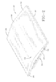
FIG. 2 is a top perspective view of an antenna assembly configured pursuant to the invention. -
FIG. 3 is an exploded bottom perspective view of the antenna assembly ofFIG. 2 . -
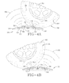
FIG. 4A is a schematic representation of a vehicle tire initial travel over the antenna assembly. -
FIG. 4B is a schematic representation of a the vehicle tire traveling over a rearward surface portion of the antenna assembly. -
FIG. 5 is a schematic representation of a read station in which four antenna assemblies are positioned to intercept four vehicle tires and transmit downloaded data from the transmitting devices in the tires to a remote data processing computer. -
FIG. 6 is a top perspective view of a center unit of an alternative embodiment of an antenna assembly configured pursuant to the invention. -
FIG. 7 is a partially exploded bottom perspective view of the center unit. -
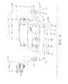
FIG. 8 is a bottom partially exploded view of the three unit alternative antenna assembly embodiment. -
FIG. 9 is a schematic representation of a read station in which four three-component antenna assemblies are positioned to intercept truck tires and transmit downloaded data from the transmitting devices in the tires to a remote data processing computer. - Referring to
FIGS. 1A and 1B , a schematic of anantenna system 10 is shown including anantenna 12 positioned flat on aground surface 14. Theantenna 12 generates a field or beam pattern 16 for the purpose of receivingdata transmission signals 20 from an approachingelectronic device 18.Device 18 is of a type commercially available and used, such as a radio frequency identification (RFID) tag. Thetag 18 may be mounted to a product that moves toward and away from a read station in which theantenna 12 and its generated beam pattern 16 is situated. The speed at which thetag 18 approaches and leaves the vicinity of theantenna 12 will affect the time interval in which the transmitteddata 20 is received by the antenna field 16. The read range of theantenna 12 is increased and represented by the shaded region 17 of the field 16. A maximized read range will positively affect the coupling efficiency between the transmittedsignal 20 and the antenna field 16 and serve to promote a complete and accurate data transmission as the tag approaches and leaves the vicinity of theantenna 12. -
FIG. 1B shows an alternative antenna position within a read station in which theantenna 12 is tilted toward the approach path of thetag 18. Tilting of theantenna 12 at an acute angle α with respect to theground surface 14 will cause the beam pattern 16 to tilt at angle α toward the approach path (represented by data transmission 20) of thetag 18. The tilting of the field 16 toward the approach path of thetag 18 serves to enlarge the read field 17 as shown by the larger shaded region ofFIG. 1B as compared with the shaded region ofFIG. 1A . The read range of theantenna 12 is thus maximized by introducing a mechanical tilt at angle α. The enlargement of the read range 17 effected by mechanically tilting theantenna 12 improves the reliability of the system and ensures that transmitted data will be captured as thetag 18 moves through the read zone. With the mechanical tilt, more of the cross-sectional area of the antenna pattern 16 is available and improved transmission efficiency is gained. - With reference to
FIGS. 2 and3 , a tilted antenna system stand 22 is shown to include a standfreestanding base 24 supported byelongate support legs 26, 27, 28, and 29. The support legs affix to an underside of thebase 24 along outer peripheral locations and for support of the base on a ground surface. Thestand 22 is provided with acover 30 having a convex profile that covers the top of thebase 24. As used herein, "convex" is meant in a general sense. The cover upper convex surface may be composed of adjoining flat surface segments or be continuously radiussed as shown. The base is formed of any suitably strong material such as plastic, and is configured having a protrudinglatch finger 32 andlatch slot 33 spaced apart along each side of the stand. Thefinger 32 is shaped to interlock with theslot 33 of a like-configured unit to thereby chain multiple stands together in a series. Thestand cover 30 is of convex sectional configuration, formed to include a forwardinclined surface 34 extending to an apex or crown 36, and a rearwardinclined surface 38 extending from the crown 36 to a rearward side of the stand. A matrix ofcross-ribs 40 may be molded into the underside of thebase 24 for adding strength to the structure. - The cross-ribs 40 define a forward antenna receiving recess 42 with support notches 44 formed in ribs along the sides of the recess 42. A similarly configured rearward antenna receiving recess 46 is positioned between the cross-ribs 40 of the rearward portion of the base, likewise providing support notches 48 formed in ribs along the sides of the rearward recess 46. A forward antenna 50 is sized to fit within the forward recess 42, resting upon notches 44. A rearward antenna 52 is positioned within rearward recess 46 and rests upon the notches 48. The notches 44, 48 formed within the cross-ribs 40 form an angled seat within the recesses 42, 46 such that the antennae 50, 52 when positioned within the recesses are at an acute angle with respect to a vertical centerline of the
stand 22. The antennae 50, 52 angle in opposite directions from the centerline at an acute angle α (seeFIG. 1B ) which is preferably between 13 to 15 degrees, although angles of different magnitudes may be used respectively for the two antenna in order to create the antenna field desired. - It will be appreciated that the
cover 30 is formed of RF transparent material and serves to enclose the antennae 50, 52 in their angled position within the stand. Assembly posts 54, 56 mate within sockets formed in the cover to attach the cover to theground surface 14 inFIGS 1A and 1B . The antennae 50, 52 are angled within thebase 24 at the aforementioned acute angle which may be the same for each antenna or different, depending on the system objectives and requirements. In the assembled condition, the antennae 50, 52 generally reside beneath the inclined RFtransparent surfaces 34, 36, respectively. The angle of inclination of the antennae 50, 52 and thesurface portions 34, 36 may be the same or differ. Thestand assembly 22, it will be appreciated, produces a speed bump when the stand is positioned to intercept the wheels of an oncoming vehicle. The tires of the vehicle are intended to ride up theforward surface 34, over the crest or apex 38, and down the rearwardinclined surface 38. The slopes ofinclined surfaces stand 22 will be slowed to an objective read speed. Thus, the slope of theinclined surfaces 34, 36 may be more or less than the slope of the inclined antennae 50, 52 within the stand, depending on the degree of bump necessary to slow the oncoming vehicle to an objective read speed. -
FIGS. 4A and 4B illustrate the operation of the speed bump created by thestand 22 and the tilted antenna 50, 52 positioned within the stand as a vehicle tire 58 rides up, over, and down the stand surfaces 34, 36, 38. The tire 58 includes asidewall 60 and mounts to a rim 62 in standard fashion. An RFID tag 64 is secured to the tire 58 by conventional means at a conventional location such as to the tire inner liner (not shown) defining the tire cavity. So positioned, the tag 64 rotates with the tire 58 at the same speed of rotation. Anantenna beam pattern 68 from the forward antenna 50 is tilted toward the tire 58 approach path as the tire engages and rolls up theinclined surface 34 of thestand 22. The tilt of the antenna 50 within thestand 22 tilts the field 66 so as to allow the signal from the tag 64 access to more of the field cross-section as tag 64 rotates with the tire. The second, rearwardly mounted antenna 52 is likewise tilted within the stand in the opposite (rearward facing) direction from the forward (forward facing) tilted antenna 50. The field or beam pattern 66 is thus tilted to the rear by the generally same angle α as theforward beam pattern 68 from antenna 50 tilts forward. It is preferred, although not necessary, that the acute tilt angle α be within the range of 13 to 15 degrees or 9 to 19 degrees. - The position of the antenna 50 relative to the antenna 52 is close enough such that the
beam patterns 66, 68 overlap to a minimal extent and cover without a gap the area above thestand 22. Thus, the tag 64, mounted to the tire 58, will rotate over thesurfaces FIGS 5 and9 . As the tag rotates, data transmission by the tag will intersect thebeam patterns 66, 68 of one or both of the antenna 50, 52. A reliable and complete transmission of data is thereby assured. - Moreover, the speed at which the tag 64 rotates with the tire 58 may be controlled by controlling the front to rear span and/or degree and/or extent of incline of the speed bump represented by
surfaces stand 22. A higher angle of tilt of the forward and rearward surface or lengthening thesurfaces 34, 36, and/or 38 raises the "bump" and will generally obligate the driver of the vehicle to slow down to a greater extent. This, in turn, slows the rotational speed of the tire and tag 64 over thestand 22 and elongates the time period (read interval) during which the tag transmission may be communicated to theantenna patterns 66, 68. Conversely, lowering the "bump" by adjusting the angle of tilt and/or width of stand surfaces 34, 36, and 38 will obligate a driver to slow the vehicle to a lesser extent. The read interval between the tag 64 and thebeam patterns 66, 68 will be reduced accordingly. By adjusting the size (span) and/or tilt of the stand surfaces with the tilt of the antenna beam patterns, an optimal read interval may be attained that is long enough to effect a highly reliable data transmission without slowing the vehicle unnecessarily. - The tag 64 may be mounted to the inner liner of the sidewall of the tire 58 as explained. For such a mounting location, it may be beneficial to mount the antenna 50, 52 to a side of the tire 58 for improved coupling between the antenna beam pattern and the data transmission from the tag. To facilitate mounting the antenna to a side of a tire traveling over the stand, a
bridging unit 72 may be utilized in a three-component stand assembly 70 such as that shown inFIGS. 6, 7 , and8 . The tire is intended to ride directly over the bridging unit upper convex surface. The bridgingunit 72 is situated between two antenna assemblies of the type described previously. The center or bridgingunit 72 includes a body 74 having cross-rib reinforcement 76 and a convex upper surface 78. A pair of elongate support legs 80, 82 affix to an underside of the body 74 and support the body on a ground surface. A socket 84 connects the body 74 to theground surface 14 inFIGS. 1A and 1B . The cover provides the arched or convex outer surface 78 and includes a forward inclined surface 86 and a rearwardinclined surface 88, separated by an apex region 87. The forward and rearward surfaces 86, 88 have an acute tilt angle generally the same as the forward and rearward surfaces of the cover 30 (FIGS. 2 and3 ) described previously. The bridging unit body 74 is formed to provide a latch finger 92 and alatch slot 90 along each longitudinal side that mate and interconnect with thelatch 32 andlatch slot 33 of thebase 24. Accordingly, a three component series may be interconnected consisting of two antenna stands 22 on opposite side of a singlebridging stand unit 72 as shown inFIG. 8 . The center or bridging unit surfaces 86, 88 are targeted by a vehicle operator and tire 58 rides up and over the center unit during a drive-through read operation. - The incline of the
surfaces 86, 88 complement the incline ofsurfaces antenna assembly 22. In the three component version of the invention, the twoantenna assemblies 22 on opposite sides of thecenter unit 72 are to the side of the tire 58 and function to ensure that a complete and accurate data transmission between the tag 64 and the antenna 50, 52 will occur. The tilt of the antenna 50, 52 within each of theantenna assemblies 22 on opposite sides of thecenter unit 72 is generally the same, and it is preferred that the tilt angle be generally 13-15 degrees although more or less tilt may be employed if desired. - With reference to
FIGS 4A and 4B , the tag 64 rotates with the tire 58. It is desirable to slow the vehicle by means of the speed bump formed one or twoantenna stand assemblies 22 and, if desired, bridgingunit 72. A single antenna stand assembly may be employed if it is preferred that the tire ride directly over the convex surface of RFIDtransparent cover 30. If an adjacent position of the antenna 50 and/or 52 is desired, standassembly 22 may be used with abridging unit 72. The tire rides over the bridgingunit 72 in such a configuration with the antenna members 50, 52 positioned to the side. It is preferable that the speed bump configuration slow the rotational rate of the vehicle tire 58 to a targeted reduced rotational read rate optimal for effecting reliable data transmission as the tire passes over the convex upper surface. The size, shape and height of the bump will be selected to induce the vehicle operator to lower the speed of the vehicle to achieve the targeted reduced rotational read rate speed. The span and degree of incline created bysurfaces surface 86, 87, and 88 if abridging unit 72 is employed, is constructed to operatively require the tire and the transmitting device 64 to at least complete one revolution over a stand and/or multiple antenna component assemblies 70 as shown inFIGS. 5 and9 at the targeted reduced rotational read rate speed as the tire traverses over the bump. Thefields 66, 68 are established above the tire path across the path in such a manner so as to continuously maintain the tag within one or the other or both of thefields 66, 68 as the tire rotates at the reduced read rate speed across the bump. In so doing, data transmission between the tag and the antenna fields is continuous and highly reliable and accurate transmission of data is facilitated. -
FIGS. 5 and9 illustrate the deployment of a three-component antenna assembly system into a read station for a passenger car (FIG. 5 ) station and for a cargo truck drive-through station (FIG. 9 ). InFIG. 5 , four three-component assemblies 70 are positioned to intercept the four tires on a passenger car and form a drive-through read station. The car is driven through the station and the vehicle tires encounter the four stand assemblies generally simultaneously. The driver steers the tires toward and over thecenter unit 72 of each three-component stand and, upon encountering the four "bumps", slows the vehicle to an optimal read speed. As the tires travel over thecenter units 72, respectively, the twoantenna assembly units 22 on opposite sides of each center unit engage the tag on each tire and data transmission from the tag to the antenna within eachunit 22 is established and completed. At the reduced vehicle speed caused by the speed bumps, the optimal time interval required to effect complete data transmission is achieved. Data downloaded to the antenna may then be conducted by wiring 100 to a transmitting device 102 for wireless data transmission to aprocessing computer 104. - In
FIG. 9 , four three-component assemblies 70 are positioned to intercept the tires on a cargo truck and form a drive-through read station. The truck 94 may have a pair of forward tires and dual tandem tires in the rear as shown. The truck 94 is driven through the station and the vehicle tires encounter the four stand assemblies 70 generally simultaneously. The driver steers the tires toward and over thecenter unit 72 of each three-component stand 70 and, upon encountering the four "bumps", slows the vehicle to an optimal reduced read speed. As the tires travel over thecenter units 72, respectively, the twoantenna assembly units 22 on opposite sides of each center unit engage the tag of each tire and data transmission from the tag to the antenna within eachunit 22 is established and completed. At the reduced vehicle speed caused by the speed bumps, the optimal time interval required to effect complete data transmission is achieved. The tandem tires in the rear of the truck 94 may be read simultaneously as the tires pass over thecenter bridging unit 72 by the twoassemblies 22 positioned to the side of theunit 72. Data downloaded to the antenna may then be conducted by wiring 100 to a transmitting device 102 for wireless data transmission to aprocessing computer 104. - With reference to
FIGS. 4A and 4B and9 , as described previously, the bumps created by the assemblies 70 are configured to slow the vehicle to a lower speed that will allow the tags 64 inFIGS. 4A and 4B and tags 18 and 20 inFIG. 9 to rotate at least one complete revolution as the tire carrying the tag passes over a stand and/or multiple antenna component assemblies 70 as shown inFIGS. 5 and9 through the fields created by antenna 50, 52. The fields created by antenna 50, 52 are positioned to keep read contact with the tag throughout its revolution over the speed bump to insure a reliable and accurate data transmission. The tilt of the antenna 50 orients its field pattern toward the tire as the tire engages and rides up onto the assembly 70 and the tilt of antenna 52 orients its field pattern toward the tire as the tire travels down a rearward surface portion of the assembly 70 and exits. - With reference to
FIGS. 4A and 4B and9 , as described previously, the bumps created by the assemblies 70 are configured to slow the vehicle to a lower speed that will allow the tags 64 inFIGS. 4A and 4B and tags 18 and 20 inFIG. 9 to rotate at least one complete revolution as the tire carrying the tag passes over a stand and/or multiple antenna component assemblies 70 as shown inFIGS. 5 and9 through the fields created by antenna 50, 52. The fields created by antenna 50, 52 are positioned to keep read contact with the tag throughout its revolution over the speed bump to insure a reliable and accurate data transmission. The tilt of the antenna 50 orients its field pattern toward the tire as the tire engages and rides up onto the assembly 70 and the tilt of antenna 52 orients its field pattern toward the tire as the tire travels down a rearward surface portion of the assembly 70 and exits.
Claims (15)
- An antenna assembly for receiving a data transmission from an electronic transmitting device (18) mounted to a vehicle (94), the vehicle (94) having at least one tire assembly including a tire (58), the antenna assembly (10) comprising:a stand (22) having a convex upper surface (30) operative to intercept and engage the tire (58) as the tire (58) passes over the stand (22);at least one antenna (50, 52) proximally mounted with respect to the stand (22), the at least one antenna (50, 52) having a directionally aimed antenna field (66) operative to receive the data transmission from the electronic transmitting device (18) as the tire (58) passes over the convex upper surface (30).
- The antenna assembly of claim 1 wherein the stand (22) is designed to operatively slow down the rotational rate of the tire (58) to a targeted reduced rotational read rate or to a targeted reduced rotational read rate range as the tire (58) passes over the convex upper surface (30).
- The antenna assembly of claim 2 wherein the at least one antenna (50, 52) is designed to operatively receive the data transmission from the electronic transmitting device (18) as the tire (58) passes over the convex upper surface (30) at the reduced rotational read rate or read rate range.
- The antenna assembly of at least one of the previous claims wherein the at least one antenna (50, 52) is positioned such that the directionally aimed antenna field (66) is tilted at an acute tilt angle (α) toward an approach path of the tire (58) onto the convex upper surface (30), the acute tilt angle (α) of the directionally aimed one antenna field (66) being preferably within a range of from 9 to 19 degrees or from 13 to 15 degrees to a horizontal ground plane.
- The antenna assembly of at least one of the previous claims wherein the convex upper surface (30) includes a leading inclined surface portion (34) for tire engagement tilted at an acute tilt angle (α) preferably in a range of from 9 to 19 degrees or from 13 to 15 degrees with respect to a horizontal ground plane.
- The antenna assembly of at least one of the previous claims wherein the convex upper surface (30) and the at least one antenna (50, 52) are attached to a common stand base member, the at least one antenna (50, 52) being preferably mounted to the stand base member (22) below the upper convex surface (30).
- The antenna assembly of at least one of the previous claims wherein the at least one antenna (50, 52) is positioned adjacent to the convex upper surface (30) affixed to a stand base member.
- The antenna assembly of at least one of the previous claims wherein the upper convex surface (30) has a leading end to a trailing end surface span sufficient to operatively require the tire (58) and the transmitting device (18) to substantially complete at least one revolution as the tire (58) passes over the upper convex surface span.
- The antenna assembly of claim 8 wherein the transmitting device (18) is mounted to the tire assembly or the tire (58) and rotates with the tire (58), and wherein the leading end to trailing end surface span is sufficient to operatively require the tire (58) and the transmitting device (18) to substantially complete at least one revolution as the tire (58) passes over the upper convex surface span at the targeted reduced rotational read rate.
- The antenna assembly of at least one of the previous claims further comprising at least one second antenna (52) proximally mounted with respect to the stand (22), the at least one second antenna (52) having a directionally aimed second antenna field operative to receive the data transmission from the electronic transmitting device (18) as the tire (58) passes over the convex upper surface (30).
- The antenna assembly of at least one of the previous claims wherein the directionally aimed antenna field (66) is tilted at an acute tilt angle (α) preferably in a range of from 9 to 19 degrees or from 13 to 15 degrees toward an approach path of the tire (58) onto the convex upper surface (30) and the second directionally aimed antenna field is tilted at an acute tilt angle (α) preferably in a range of from 9 to 19 degrees or from 13 to 15 degrees toward an exit path of the tire (58) along a trailing portion of the convex upper surface (30).
- The antenna assembly of at least one of the previous claims wherein the antenna assembly is designed such that the first antenna field (66) and the second antenna field are operatively positioned to place the electronic transmitting device (18) into a continuously coupled relationship with at least one of the first and second antenna fields as the tire (58) passes across the convex upper surface (30).
- The antenna assembly of at least one of the previous claims wherein the at least one antenna field (66) at least substantially faces in a common direction with a leading portion (34) of the convex upper surface (30) of the stand (22), and/or wherein the at least one antenna field (66) and a leading portion (34) of the convex upper surface (30) of the stand (22) face toward an approach path of the tire (58) onto the convex upper surface (30).
- The antenna assembly of at least one of the previous claims wherein the at least one antenna (50, 52) mounts to a stand base member below a lateral convex surface closely adjacent to the upper convex surface (30), the lateral convex surface preferably having a complementary concavity with the upper convex surface (30).
- A method of reading a data transmission from an electronic transmitting device (18) mounted to a vehicle tire assembly, the method comprising:positioning a convex upper surface (30) of a stand (22) to intercept a tire (58) of the vehicle tire assembly;establishing rotational engagement between the tire (58) and the convex upper surface (30) to slow the speed of the vehicle and to reduce the rotational rate at which the tire rotates to a targeted reduced rotational read rate or a targeted reduced rotational read rate range;directing an antenna field (66) from at least one antenna (50, 52) toward an approach path of the tire (58) to the convex upper surface (30) of the stand (22) to receive data transmission from the electronic transmitting device (18) as the tire passes over the convex upper surface (30) at the targeted reduced rotational read rate or the targeted reduced rotational read rate range.
Applications Claiming Priority (2)
| Application Number | Priority Date | Filing Date | Title |
|---|---|---|---|
| US12/640,024 US9135479B2 (en) | 2009-12-17 | 2009-12-17 | Antenna assembly for a tag reader |
| US12/640,028 US20110148593A1 (en) | 2009-12-17 | 2009-12-17 | Method for reading a vehicle tag within a read station |
Publications (2)
| Publication Number | Publication Date |
|---|---|
| EP2339692A1 true EP2339692A1 (en) | 2011-06-29 |
| EP2339692B1 EP2339692B1 (en) | 2012-11-14 |
Family
ID=43742432
Family Applications (1)
| Application Number | Title | Priority Date | Filing Date |
|---|---|---|---|
| EP20100194979 Not-in-force EP2339692B1 (en) | 2009-12-17 | 2010-12-14 | Antenna assembly for a tag reader and method of reading transmission data |
Country Status (1)
| Country | Link |
|---|---|
| EP (1) | EP2339692B1 (en) |
Cited By (1)
| Publication number | Priority date | Publication date | Assignee | Title |
|---|---|---|---|---|
| EP2829659A1 (en) * | 2013-07-26 | 2015-01-28 | The Goodyear Tire & Rubber Company | Drive-over stand and antenna assembly |
Citations (1)
| Publication number | Priority date | Publication date | Assignee | Title |
|---|---|---|---|---|
| WO2005036694A2 (en) * | 2003-10-02 | 2005-04-21 | Emag Technologies, Inc. | Antenna system embedded in a support structure for interrogating a tire sensor transponder |
-
2010
- 2010-12-14 EP EP20100194979 patent/EP2339692B1/en not_active Not-in-force
Patent Citations (1)
| Publication number | Priority date | Publication date | Assignee | Title |
|---|---|---|---|---|
| WO2005036694A2 (en) * | 2003-10-02 | 2005-04-21 | Emag Technologies, Inc. | Antenna system embedded in a support structure for interrogating a tire sensor transponder |
Cited By (2)
| Publication number | Priority date | Publication date | Assignee | Title |
|---|---|---|---|---|
| EP2829659A1 (en) * | 2013-07-26 | 2015-01-28 | The Goodyear Tire & Rubber Company | Drive-over stand and antenna assembly |
| US9183423B2 (en) | 2013-07-26 | 2015-11-10 | The Goodyear Tire & Rubber Company | Drive-over stand and antenna assembly |
Also Published As
| Publication number | Publication date |
|---|---|
| EP2339692B1 (en) | 2012-11-14 |
Similar Documents
| Publication | Publication Date | Title |
|---|---|---|
| US20110148593A1 (en) | Method for reading a vehicle tag within a read station | |
| JP6380976B2 (en) | Riding stand and antenna assembly | |
| US9135479B2 (en) | Antenna assembly for a tag reader | |
| ES2989765T3 (en) | Systems and methods for automated loading and unloading at a dock station | |
| EP2146303B1 (en) | Reader and method for wheel-based RFID devices | |
| US9679174B2 (en) | System for the dynamic reading of data from transponders | |
| US9754138B2 (en) | System for the dynamic reading of data from transponders | |
| EP3661236A1 (en) | Electronic fence and electronic fence system | |
| US6087975A (en) | Object detecting system for vehicle | |
| JP4000891B2 (en) | Tire condition acquisition device | |
| RU2610042C2 (en) | Automatic grinding machine, as well as crushed material unloading method | |
| CA3097517C (en) | Underbody radar units | |
| CN102582542A (en) | Front-end structure of a motor vehicle | |
| EP2339692B1 (en) | Antenna assembly for a tag reader and method of reading transmission data | |
| US9070973B2 (en) | Control vehicle for a road toll system | |
| US20170184248A1 (en) | Vehicle positioning apparatus | |
| JP3355401B2 (en) | Vehicle position detection device | |
| US20100081358A1 (en) | Toy vehicle and terrain monitoring system used therein | |
| US20040263404A1 (en) | HF wheel rim antenna having several patch antennas | |
| JP3319194B2 (en) | Automatic guided vehicle | |
| IE87085B1 (en) | A system for steering a trailer towards a payload | |
| CN117246386A (en) | An intelligent following cargo vehicle | |
| JP2001116840A (en) | Vehicle radar system | |
| KR102681107B1 (en) | Ultra-thin mobile which transports structures for testing autonomous driving performance of vehicles | |
| JPH08164848A (en) | Automatic guided vehicle |
Legal Events
| Date | Code | Title | Description |
|---|---|---|---|
| PUAI | Public reference made under article 153(3) epc to a published international application that has entered the european phase |
Free format text: ORIGINAL CODE: 0009012 |
|
| AK | Designated contracting states |
Kind code of ref document: A1 Designated state(s): AL AT BE BG CH CY CZ DE DK EE ES FI FR GB GR HR HU IE IS IT LI LT LU LV MC MK MT NL NO PL PT RO RS SE SI SK SM TR |
|
| AX | Request for extension of the european patent |
Extension state: BA ME |
|
| 17P | Request for examination filed |
Effective date: 20111229 |
|
| RIC1 | Information provided on ipc code assigned before grant |
Ipc: G07C 5/00 20060101ALI20120223BHEP Ipc: G06K 7/10 20060101ALI20120223BHEP Ipc: B60C 23/04 20060101ALI20120223BHEP Ipc: H01Q 1/22 20060101AFI20120223BHEP |
|
| GRAP | Despatch of communication of intention to grant a patent |
Free format text: ORIGINAL CODE: EPIDOSNIGR1 |
|
| GRAS | Grant fee paid |
Free format text: ORIGINAL CODE: EPIDOSNIGR3 |
|
| GRAA | (expected) grant |
Free format text: ORIGINAL CODE: 0009210 |
|
| AK | Designated contracting states |
Kind code of ref document: B1 Designated state(s): AL AT BE BG CH CY CZ DE DK EE ES FI FR GB GR HR HU IE IS IT LI LT LU LV MC MK MT NL NO PL PT RO RS SE SI SK SM TR |
|
| REG | Reference to a national code |
Ref country code: GB Ref legal event code: FG4D |
|
| REG | Reference to a national code |
Ref country code: AT Ref legal event code: REF Ref document number: 584392 Country of ref document: AT Kind code of ref document: T Effective date: 20121115 Ref country code: CH Ref legal event code: EP |
|
| REG | Reference to a national code |
Ref country code: IE Ref legal event code: FG4D |
|
| REG | Reference to a national code |
Ref country code: DE Ref legal event code: R096 Ref document number: 602010003610 Country of ref document: DE Effective date: 20130110 |
|
| REG | Reference to a national code |
Ref country code: NL Ref legal event code: VDEP Effective date: 20121114 |
|
| REG | Reference to a national code |
Ref country code: AT Ref legal event code: MK05 Ref document number: 584392 Country of ref document: AT Kind code of ref document: T Effective date: 20121114 |
|
| REG | Reference to a national code |
Ref country code: LT Ref legal event code: MG4D |
|
| PG25 | Lapsed in a contracting state [announced via postgrant information from national office to epo] |
Ref country code: FI Free format text: LAPSE BECAUSE OF FAILURE TO SUBMIT A TRANSLATION OF THE DESCRIPTION OR TO PAY THE FEE WITHIN THE PRESCRIBED TIME-LIMIT Effective date: 20121114 Ref country code: NO Free format text: LAPSE BECAUSE OF FAILURE TO SUBMIT A TRANSLATION OF THE DESCRIPTION OR TO PAY THE FEE WITHIN THE PRESCRIBED TIME-LIMIT Effective date: 20130214 Ref country code: ES Free format text: LAPSE BECAUSE OF FAILURE TO SUBMIT A TRANSLATION OF THE DESCRIPTION OR TO PAY THE FEE WITHIN THE PRESCRIBED TIME-LIMIT Effective date: 20130225 Ref country code: LT Free format text: LAPSE BECAUSE OF FAILURE TO SUBMIT A TRANSLATION OF THE DESCRIPTION OR TO PAY THE FEE WITHIN THE PRESCRIBED TIME-LIMIT Effective date: 20121114 Ref country code: HR Free format text: LAPSE BECAUSE OF FAILURE TO SUBMIT A TRANSLATION OF THE DESCRIPTION OR TO PAY THE FEE WITHIN THE PRESCRIBED TIME-LIMIT Effective date: 20121114 Ref country code: SE Free format text: LAPSE BECAUSE OF FAILURE TO SUBMIT A TRANSLATION OF THE DESCRIPTION OR TO PAY THE FEE WITHIN THE PRESCRIBED TIME-LIMIT Effective date: 20121114 |
|
| PG25 | Lapsed in a contracting state [announced via postgrant information from national office to epo] |
Ref country code: LV Free format text: LAPSE BECAUSE OF FAILURE TO SUBMIT A TRANSLATION OF THE DESCRIPTION OR TO PAY THE FEE WITHIN THE PRESCRIBED TIME-LIMIT Effective date: 20121114 Ref country code: BE Free format text: LAPSE BECAUSE OF FAILURE TO SUBMIT A TRANSLATION OF THE DESCRIPTION OR TO PAY THE FEE WITHIN THE PRESCRIBED TIME-LIMIT Effective date: 20121114 Ref country code: SI Free format text: LAPSE BECAUSE OF FAILURE TO SUBMIT A TRANSLATION OF THE DESCRIPTION OR TO PAY THE FEE WITHIN THE PRESCRIBED TIME-LIMIT Effective date: 20121114 Ref country code: GR Free format text: LAPSE BECAUSE OF FAILURE TO SUBMIT A TRANSLATION OF THE DESCRIPTION OR TO PAY THE FEE WITHIN THE PRESCRIBED TIME-LIMIT Effective date: 20130215 Ref country code: PT Free format text: LAPSE BECAUSE OF FAILURE TO SUBMIT A TRANSLATION OF THE DESCRIPTION OR TO PAY THE FEE WITHIN THE PRESCRIBED TIME-LIMIT Effective date: 20130314 Ref country code: PL Free format text: LAPSE BECAUSE OF FAILURE TO SUBMIT A TRANSLATION OF THE DESCRIPTION OR TO PAY THE FEE WITHIN THE PRESCRIBED TIME-LIMIT Effective date: 20121114 |
|
| PG25 | Lapsed in a contracting state [announced via postgrant information from national office to epo] |
Ref country code: AT Free format text: LAPSE BECAUSE OF FAILURE TO SUBMIT A TRANSLATION OF THE DESCRIPTION OR TO PAY THE FEE WITHIN THE PRESCRIBED TIME-LIMIT Effective date: 20121114 |
|
| PG25 | Lapsed in a contracting state [announced via postgrant information from national office to epo] |
Ref country code: EE Free format text: LAPSE BECAUSE OF FAILURE TO SUBMIT A TRANSLATION OF THE DESCRIPTION OR TO PAY THE FEE WITHIN THE PRESCRIBED TIME-LIMIT Effective date: 20121114 Ref country code: BG Free format text: LAPSE BECAUSE OF FAILURE TO SUBMIT A TRANSLATION OF THE DESCRIPTION OR TO PAY THE FEE WITHIN THE PRESCRIBED TIME-LIMIT Effective date: 20130214 Ref country code: RS Free format text: LAPSE BECAUSE OF FAILURE TO SUBMIT A TRANSLATION OF THE DESCRIPTION OR TO PAY THE FEE WITHIN THE PRESCRIBED TIME-LIMIT Effective date: 20121114 Ref country code: DK Free format text: LAPSE BECAUSE OF FAILURE TO SUBMIT A TRANSLATION OF THE DESCRIPTION OR TO PAY THE FEE WITHIN THE PRESCRIBED TIME-LIMIT Effective date: 20121114 Ref country code: CZ Free format text: LAPSE BECAUSE OF FAILURE TO SUBMIT A TRANSLATION OF THE DESCRIPTION OR TO PAY THE FEE WITHIN THE PRESCRIBED TIME-LIMIT Effective date: 20121114 Ref country code: MC Free format text: LAPSE BECAUSE OF NON-PAYMENT OF DUE FEES Effective date: 20121231 Ref country code: SK Free format text: LAPSE BECAUSE OF FAILURE TO SUBMIT A TRANSLATION OF THE DESCRIPTION OR TO PAY THE FEE WITHIN THE PRESCRIBED TIME-LIMIT Effective date: 20121114 |
|
| PG25 | Lapsed in a contracting state [announced via postgrant information from national office to epo] |
Ref country code: NL Free format text: LAPSE BECAUSE OF FAILURE TO SUBMIT A TRANSLATION OF THE DESCRIPTION OR TO PAY THE FEE WITHIN THE PRESCRIBED TIME-LIMIT Effective date: 20121114 Ref country code: RO Free format text: LAPSE BECAUSE OF FAILURE TO SUBMIT A TRANSLATION OF THE DESCRIPTION OR TO PAY THE FEE WITHIN THE PRESCRIBED TIME-LIMIT Effective date: 20121114 |
|
| PLBE | No opposition filed within time limit |
Free format text: ORIGINAL CODE: 0009261 |
|
| STAA | Information on the status of an ep patent application or granted ep patent |
Free format text: STATUS: NO OPPOSITION FILED WITHIN TIME LIMIT |
|
| REG | Reference to a national code |
Ref country code: IE Ref legal event code: MM4A |
|
| 26N | No opposition filed |
Effective date: 20130815 |
|
| PG25 | Lapsed in a contracting state [announced via postgrant information from national office to epo] |
Ref country code: IE Free format text: LAPSE BECAUSE OF NON-PAYMENT OF DUE FEES Effective date: 20121214 |
|
| PG25 | Lapsed in a contracting state [announced via postgrant information from national office to epo] |
Ref country code: MT Free format text: LAPSE BECAUSE OF FAILURE TO SUBMIT A TRANSLATION OF THE DESCRIPTION OR TO PAY THE FEE WITHIN THE PRESCRIBED TIME-LIMIT Effective date: 20121114 Ref country code: CY Free format text: LAPSE BECAUSE OF FAILURE TO SUBMIT A TRANSLATION OF THE DESCRIPTION OR TO PAY THE FEE WITHIN THE PRESCRIBED TIME-LIMIT Effective date: 20121114 Ref country code: AL Free format text: LAPSE BECAUSE OF FAILURE TO SUBMIT A TRANSLATION OF THE DESCRIPTION OR TO PAY THE FEE WITHIN THE PRESCRIBED TIME-LIMIT Effective date: 20121114 |
|
| REG | Reference to a national code |
Ref country code: DE Ref legal event code: R097 Ref document number: 602010003610 Country of ref document: DE Effective date: 20130815 |
|
| PG25 | Lapsed in a contracting state [announced via postgrant information from national office to epo] |
Ref country code: TR Free format text: LAPSE BECAUSE OF FAILURE TO SUBMIT A TRANSLATION OF THE DESCRIPTION OR TO PAY THE FEE WITHIN THE PRESCRIBED TIME-LIMIT Effective date: 20121114 |
|
| PG25 | Lapsed in a contracting state [announced via postgrant information from national office to epo] |
Ref country code: LU Free format text: LAPSE BECAUSE OF NON-PAYMENT OF DUE FEES Effective date: 20121214 Ref country code: SM Free format text: LAPSE BECAUSE OF FAILURE TO SUBMIT A TRANSLATION OF THE DESCRIPTION OR TO PAY THE FEE WITHIN THE PRESCRIBED TIME-LIMIT Effective date: 20121114 |
|
| PG25 | Lapsed in a contracting state [announced via postgrant information from national office to epo] |
Ref country code: HU Free format text: LAPSE BECAUSE OF FAILURE TO SUBMIT A TRANSLATION OF THE DESCRIPTION OR TO PAY THE FEE WITHIN THE PRESCRIBED TIME-LIMIT Effective date: 20101214 |
|
| PG25 | Lapsed in a contracting state [announced via postgrant information from national office to epo] |
Ref country code: MK Free format text: LAPSE BECAUSE OF FAILURE TO SUBMIT A TRANSLATION OF THE DESCRIPTION OR TO PAY THE FEE WITHIN THE PRESCRIBED TIME-LIMIT Effective date: 20121114 |
|
| REG | Reference to a national code |
Ref country code: CH Ref legal event code: PL |
|
| GBPC | Gb: european patent ceased through non-payment of renewal fee |
Effective date: 20141214 |
|
| PG25 | Lapsed in a contracting state [announced via postgrant information from national office to epo] |
Ref country code: CH Free format text: LAPSE BECAUSE OF NON-PAYMENT OF DUE FEES Effective date: 20141231 Ref country code: GB Free format text: LAPSE BECAUSE OF NON-PAYMENT OF DUE FEES Effective date: 20141214 Ref country code: LI Free format text: LAPSE BECAUSE OF NON-PAYMENT OF DUE FEES Effective date: 20141231 |
|
| REG | Reference to a national code |
Ref country code: FR Ref legal event code: PLFP Year of fee payment: 6 |
|
| PG25 | Lapsed in a contracting state [announced via postgrant information from national office to epo] |
Ref country code: IS Free format text: LAPSE BECAUSE OF FAILURE TO SUBMIT A TRANSLATION OF THE DESCRIPTION OR TO PAY THE FEE WITHIN THE PRESCRIBED TIME-LIMIT Effective date: 20121114 |
|
| REG | Reference to a national code |
Ref country code: FR Ref legal event code: PLFP Year of fee payment: 7 |
|
| REG | Reference to a national code |
Ref country code: FR Ref legal event code: PLFP Year of fee payment: 8 |
|
| PGFP | Annual fee paid to national office [announced via postgrant information from national office to epo] |
Ref country code: IT Payment date: 20211110 Year of fee payment: 12 |
|
| PGFP | Annual fee paid to national office [announced via postgrant information from national office to epo] |
Ref country code: FR Payment date: 20221010 Year of fee payment: 13 |
|
| PGFP | Annual fee paid to national office [announced via postgrant information from national office to epo] |
Ref country code: DE Payment date: 20221018 Year of fee payment: 13 |
|
| PG25 | Lapsed in a contracting state [announced via postgrant information from national office to epo] |
Ref country code: IT Free format text: LAPSE BECAUSE OF NON-PAYMENT OF DUE FEES Effective date: 20221214 |
|
| REG | Reference to a national code |
Ref country code: DE Ref legal event code: R119 Ref document number: 602010003610 Country of ref document: DE |
|
| PG25 | Lapsed in a contracting state [announced via postgrant information from national office to epo] |
Ref country code: DE Free format text: LAPSE BECAUSE OF NON-PAYMENT OF DUE FEES Effective date: 20240702 |
|
| PG25 | Lapsed in a contracting state [announced via postgrant information from national office to epo] |
Ref country code: FR Free format text: LAPSE BECAUSE OF NON-PAYMENT OF DUE FEES Effective date: 20231231 |
|
| PG25 | Lapsed in a contracting state [announced via postgrant information from national office to epo] |
Ref country code: FR Free format text: LAPSE BECAUSE OF NON-PAYMENT OF DUE FEES Effective date: 20231231 Ref country code: DE Free format text: LAPSE BECAUSE OF NON-PAYMENT OF DUE FEES Effective date: 20240702 |