EP2339691A1 - Physically non-uniform TEM-mode directional coupler - Google Patents
Physically non-uniform TEM-mode directional coupler Download PDFInfo
- Publication number
- EP2339691A1 EP2339691A1 EP09290946A EP09290946A EP2339691A1 EP 2339691 A1 EP2339691 A1 EP 2339691A1 EP 09290946 A EP09290946 A EP 09290946A EP 09290946 A EP09290946 A EP 09290946A EP 2339691 A1 EP2339691 A1 EP 2339691A1
- Authority
- EP
- European Patent Office
- Prior art keywords
- conductor
- electrical conductor
- section
- directional coupler
- crossing
- Prior art date
- Legal status (The legal status is an assumption and is not a legal conclusion. Google has not performed a legal analysis and makes no representation as to the accuracy of the status listed.)
- Granted
Links
Images

Classifications
-
- H—ELECTRICITY
- H01—ELECTRIC ELEMENTS
- H01P—WAVEGUIDES; RESONATORS, LINES, OR OTHER DEVICES OF THE WAVEGUIDE TYPE
- H01P5/00—Coupling devices of the waveguide type
- H01P5/12—Coupling devices having more than two ports
- H01P5/16—Conjugate devices, i.e. devices having at least one port decoupled from one other port
- H01P5/18—Conjugate devices, i.e. devices having at least one port decoupled from one other port consisting of two coupled guides, e.g. directional couplers
- H01P5/184—Conjugate devices, i.e. devices having at least one port decoupled from one other port consisting of two coupled guides, e.g. directional couplers the guides being strip lines or microstrips
- H01P5/187—Broadside coupled lines
Definitions
- the invention relates to transverse electromagnetically coupled lines, more particularly to a transverse electromagnetic mode directional coupler.
- Transverse electromagnetic mode directional couplers are usually designed physically and electrically uniform. Traditionally, such couplers are both physically and electrically uniform. Physical uniformity denotes a geometry where both conductors are running parallel and have a constant width over the length of the coupling section, which is usually a quarter of a wavelength long with reference to a center frequency f c . Electrical uniformity denotes that along the length of the coupled line section, the two characteristic coupled line parameters Z 0e , Z 0o remain constant. Z 0e denotes the even-mode impedance, while Z 0o denotes the odd-mode impedance of the coupled lines.
- Some directional couplers with longer coupling sections than the quarter wavelength at the centre frequency do not keep Z 0e and Z 0o constant along the length of the coupled line section. Compared to the above mentioned directional coupler with quarter wavelength coupled line sections, these directional couplers do not have the same phase properties between their ports. These directional couplers have aperiodic high pass properties. The coupling is constant from a lower frequency limit.
- Embodiments of the invention provide a directional coupler with at least a first and a second inner electrical conductor and one outer electrical conductor.
- the outer electrical conductor surrounds the first and the second inner electrical conductor.
- the first and the second inner electrical conductor and the outer electrical conductor are adapted to be electromagnetically coupled via transverse electromagnetic mode radiation. Therein an even mode impedance and an odd mode impedance are constant along the length of the first and the second inner and the outer electrical conductor.
- the cross-sectional dimensions of the first and the second inner and the outer electrical conductor vary over the lengths of the first and the second inner and the outer electrical conductor.
- the first and second inner conductors vary such that the horizontal conductor separation increases towards the ends of the coupled line section.
- the coupled line section is thereby the section of the lines, where the lines are electromagnetically coupled via transverse electromagnetic mode radiation. This is advantageous because a transition to an external port can be realized without a need for additional decoupling means. (Additionally),In spite of the varying horizontal conductor separation the even mode impedance and the odd mode impedance of the directional coupler are constant along the length of the coupler. Thus, the directional coupler has electrically uniform coupling properties.
- Embodiments of the invention are advantageous because the coupling between the conductors is not interrupted abruptly at the ends of the coupled lines and an electrical discontinuity, which reduces the performance of the directional coupler, is avoided. Another advantage arises in the case of coupled line sections of different coupling strengths in a cascaded arrangement for obtaining wideband performance. Cascade connection of both coupling sections would be possible without a vertical step transition which would cause electrical performance limitations and mechanical complexity.
- the even-mode and odd-mode impedances Z 0e , Z 0o need to be calculated for the design. These two parameters then determine the cross-sectional dimensions of the directional coupler. If the impedances Z 0e , Z 0o are constant along the length of the coupled line section, then the coupling is uniform.
- k is constant when Z 0e and Z 0o are constant.
- the first and the second inner and the outer electrical conductor are tapered. By tapering the electrical conductors the even mode impedance and the odd mode impedance are kept constant, while the cross-sectional dimensions of the electrical conductors vary.
- Embodiments of the invention use a non-uniform coupling section with uniform electrical properties. While the coupling section is physically non-uniform, its electrical nature is in fact like that of a uniform coupling section. This seems contradictory, but is in fact possible by proper cross-sectional tapering along the length of the coupled lines. This involves shaping of the coupled conductors and the cavity in which they are located. The non-uniformity is such that the horizontal conductor separation increases towards the ends of the coupled line section. It is then easy to create a transition to an external port without the need for additional de-coupling means and/or conductor bends.
- the physically non-uniform coupling section automatically provides a clean connection between the coupling sections.
- Such a transitionless connection yields near ideal electrical performance properties for directional couplers.
- the first and the second inner electrical conductor overlap each other in an overlapping region. Outside the overlapping region the first inner electrical conductor runs parallel with respect to the second inner electrical conductor.
- the overlapping region could also be called coupling region, while the region outside the overlapping region could be called transmission region.
- the electrical conductors are electromagnetically coupled with transverse electromagnetic radiation.
- high frequency signals can be applied to or received from the electrical conductors.
- the overlap of the first and the second inner electrical conductor decreases towards a first and a second end of the first and the second inner electrical conductor. Such embodiments are advantageous for keeping the even mode and the odd mode impedance constant.
- the first and the second inner conductor cross each other in the longitudinal direction.
- the longitudinal direction is the direction of the high frequency signal propagating in the conductors.
- the outer conductor is tapered in the region where the first and the second inner conductor cross each other.
- the first inner conductor comprises a first and a second end section and a first crossing-section
- the second inner conductor comprises a third and a fourth end section and a second crossing-section.
- the first crossing-section is located in between the first and the second end section
- the second crossing-section is located in between the third and the fourth end section.
- Each end section has a rectangular shape, while each crossing-section has a parallelogram shape.
- the first and the second inner conductor cross each other in the region of the first and the second crossing-section.
- the outer conductor has a minimum cross-section area, where the first and the second crossing-section overlap each other completely.
- the outer conductor has two end sections, where the cross-section has a maximum area.
- the outer conductor is tapered such that it has a minimum cross-section area in the region, where the first and the second inner conductor overlap each other completely.
- this minimum cross-section area is located in the middle of the crossing-section.
- the invention in another aspect relates to a system comprising a directional coupler according to embodiments of the invention and at least four cables being connected to the first, the second, the third and the fourth end section of the first and the second inner conductor.
- the four cables are also connected to the outer conductor.
- the four cables are coaxial cables.
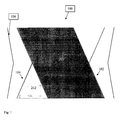
- Fig. 1 is a schematic top view of a coupling region 200 of a directional coupler 100 with a first inner conductor 102 and a second inner conductor 104. Both inner conductors 102 and 104 are surrounded by outer conductor 106. It is to be noted that only the crossing-sections 206 and 212 of the first inner conductor 102 and the second inner conductor 104 are depicted in Fig. 1 . It is a cross-sectional schematic view such that the outer conductor 106 is depicted as two lines right and left of the first inner conductor 102 and the second inner conductor 104.
- the first inner conductor 102 is located above a second inner conductor 104 with a spacing (not depicted) between the first inner conductor 102 and the second inner conductor 104.
- the first inner conductor 102 has a parallelogram shape reaching from the top left to right bottom, while the second inner conductor 104 has a parallelogram shape reaching from top right to bottom left. In the middle the first inner conductor 102 completely conceals the second inner conductor 104.
- the first inner conductor 102 and the second inner conductor 104 transmit electromagnetic radiation in transverse electromagnetic mode.
- the coupling section which is identical with the crossing-section 200, is physically non-uniform, the outer conductor 106 is tapered.
- the outer conductor 106 is tapered such that it has a minimum cross-section(al area), where the inner conductors 102 and 104 overlap each other completely. This leads to constant electromagnetic coupling between the first and the second inner conductor.
- the even-mode impedance and the odd-mode impedance are kept constant in the directional coupler 100.
- Fig. 2 is a cross-sectional schematic top view of a directional coupler 100 with a first inner conductor 102 and a second inner conductor 104. Outer conductor 106 runs right and left of the inner conductors 102 and 104.
- First inner conductor 102 and second inner conductor 104 cross each other in the crossing-section 200.
- Outer conductor 106 is tapered in the crossing-section 200.
- First inner conductor 102 consists of two end sections 202 and 204 and a crossing-section 206.
- the second inner conductor 104 consists of end sections 208 and 210 and crossing-section 212.
- the crossing-sections 206 and 212 are shaped in a parallelogram form.
- Crossing-section 206 connects end sections 202 and 204, while crossing-section 212 connects end section 208 and 210.
- End section 202 is located at the right bottom in Fig. 1
- end section 204 is located at the top left in Fig. 1 .
- the second inner conductor 104 consists of end sections 208 and 210 and crossing-section 212.
- End section 208 is located at the left bottom of Fig. 1
- end section 210 is located at the right top of Fig. 1 .
- Crossing-section 212 connects end section 208 with end section 210.
- Both crossing-sections 206 and 212 have parallelogram shape and overlap each other.
- Outer conductor 106 is tapered in the coupling region 200 and has a minimum cross-section area at the location, where crossing-sections 206 and 212 overlap each other completely.
- high frequency signals may be input at any one of the end sections 202, 204, 208 and 210.
- the signal is then transmitted from the respective end section to the other end section of the conductor. The transmission takes place through the crossing-section.
- a signal is input at end section 202, it is transmitted via crossing-section 206 to end section 204. Because of the transverse electromagnetic coupling between the first crossing-section 206 and the second crossing-section 212 an electromagnetic signal is induced into crossing-section 212. Thus, a measurable signal is output at end sections 208 and 210 of the second inner conductor 104. Usually, the energy direction in the second inner conductor 104 is opposite to the energy direction in the first inner conductor 102.
- the even mode impedance and the odd mode impedance are kept constant, although the directional coupler is not physically uniform.
- the coupling only takes place in the coupling region 200.
- the end sections 202, 204, 208 and 210 are decoupled completely.
- the coupling between the conductors has not to be interrupted abruptly and no electrical discontinuity is caused. Thereby, the performance of the directional coupler 100 is increased.
- the conductors may, for example, have bent inner and outer conductors.
- Directional coupler 102 First inner conductor 104 Second inner conductor 106 Outer conductor 200 Coupling region 202 End section 204 End section 206 Crossing-section 208 End section 210 End section 212 Crossing-section
Landscapes
- Cable Transmission Systems, Equalization Of Radio And Reduction Of Echo (AREA)
- Waveguides (AREA)
Abstract
Description
- The invention relates to transverse electromagnetically coupled lines, more particularly to a transverse electromagnetic mode directional coupler.
- Transverse electromagnetic mode directional couplers are usually designed physically and electrically uniform. Traditionally, such couplers are both physically and electrically uniform. Physical uniformity denotes a geometry where both conductors are running parallel and have a constant width over the length of the coupling section, which is usually a quarter of a wavelength long with reference to a center frequency fc. Electrical uniformity denotes that along the length of the coupled line section, the two characteristic coupled line parameters Z0e, Z0o remain constant. Z0e denotes the even-mode impedance, while Z0o denotes the odd-mode impedance of the coupled lines.
- Some directional couplers with longer coupling sections than the quarter wavelength at the centre frequency do not keep Z0e and Z0o constant along the length of the coupled line section. Compared to the above mentioned directional coupler with quarter wavelength coupled line sections, these directional couplers do not have the same phase properties between their ports. These directional couplers have aperiodic high pass properties. The coupling is constant from a lower frequency limit.
- Embodiments of the invention provide a directional coupler with at least a first and a second inner electrical conductor and one outer electrical conductor. The outer electrical conductor surrounds the first and the second inner electrical conductor. The first and the second inner electrical conductor and the outer electrical conductor are adapted to be electromagnetically coupled via transverse electromagnetic mode radiation. Therein an even mode impedance and an odd mode impedance are constant along the length of the first and the second inner and the outer electrical conductor. The cross-sectional dimensions of the first and the second inner and the outer electrical conductor vary over the lengths of the first and the second inner and the outer electrical conductor.
- Preferably, the first and second inner conductors vary such that the horizontal conductor separation increases towards the ends of the coupled line section. The coupled line section is thereby the section of the lines, where the lines are electromagnetically coupled via transverse electromagnetic mode radiation. This is advantageous because a transition to an external port can be realized without a need for additional decoupling means. (Additionally),In spite of the varying horizontal conductor separation the even mode impedance and the odd mode impedance of the directional coupler are constant along the length of the coupler. Thus, the directional coupler has electrically uniform coupling properties.
- It is to be noted that not only directional couplers may be designed in such a way. Principally, this is the case for every device with at least two coupled lines, which are characterized by the even mode impedance and the odd mode impedance.
- Embodiments of the invention are advantageous because the coupling between the conductors is not interrupted abruptly at the ends of the coupled lines and an electrical discontinuity, which reduces the performance of the directional coupler, is avoided. Another advantage arises in the case of coupled line sections of different coupling strengths in a cascaded arrangement for obtaining wideband performance. Cascade connection of both coupling sections would be possible without a vertical step transition which would cause electrical performance limitations and mechanical complexity.
- Only two electrical parameters, the even-mode and odd-mode impedances Z0e, Z0o need to be calculated for the design. These two parameters then determine the cross-sectional dimensions of the directional coupler. If the impedances Z0e, Z0o are constant along the length of the coupled line section, then the coupling is uniform.
- Z0e and Z0o are related to the port impedance Z0 of the directional coupler according to the following equation:

wherein Z0 is normally 50 Ohm. - The coupling factor k can be calculated with the following formula:

Thus, k is constant when Z0e and Z0o are constant. - According to embodiments of the invention the first and the second inner and the outer electrical conductor are tapered. By tapering the electrical conductors the even mode impedance and the odd mode impedance are kept constant, while the cross-sectional dimensions of the electrical conductors vary.
- Embodiments of the invention use a non-uniform coupling section with uniform electrical properties. While the coupling section is physically non-uniform, its electrical nature is in fact like that of a uniform coupling section. This seems contradictory, but is in fact possible by proper cross-sectional tapering along the length of the coupled lines. This involves shaping of the coupled conductors and the cavity in which they are located. The non-uniformity is such that the horizontal conductor separation increases towards the ends of the coupled line section. It is then easy to create a transition to an external port without the need for additional de-coupling means and/or conductor bends.
- In the case of cascaded coupled line sections where strong and weak coupling sections are cascaded, the physically non-uniform coupling section automatically provides a clean connection between the coupling sections. Such a transitionless connection yields near ideal electrical performance properties for directional couplers.
- According to embodiments of the invention the first and the second inner electrical conductor overlap each other in an overlapping region. Outside the overlapping region the first inner electrical conductor runs parallel with respect to the second inner electrical conductor. The overlapping region could also be called coupling region, while the region outside the overlapping region could be called transmission region. In the coupling region the electrical conductors are electromagnetically coupled with transverse electromagnetic radiation. In the transmission region high frequency signals can be applied to or received from the electrical conductors.
- According to embodiments of the invention the overlap of the first and the second inner electrical conductor decreases towards a first and a second end of the first and the second inner electrical conductor. Such embodiments are advantageous for keeping the even mode and the odd mode impedance constant.
- According to embodiments of the invention the first and the second inner conductor cross each other in the longitudinal direction. The longitudinal direction is the direction of the high frequency signal propagating in the conductors.
- According to embodiments of the invention the outer conductor is tapered in the region where the first and the second inner conductor cross each other.
- According to embodiments of the invention the first inner conductor comprises a first and a second end section and a first crossing-section, the second inner conductor comprises a third and a fourth end section and a second crossing-section. Thereby the first crossing-section is located in between the first and the second end section and the second crossing-section is located in between the third and the fourth end section. Each end section has a rectangular shape, while each crossing-section has a parallelogram shape. The first and the second inner conductor cross each other in the region of the first and the second crossing-section.
- According to embodiments of the invention the outer conductor has a minimum cross-section area, where the first and the second crossing-section overlap each other completely. In other words, the outer conductor has two end sections, where the cross-section has a maximum area. In the crossing-section of the first and the second inner conductor the outer conductor is tapered such that it has a minimum cross-section area in the region, where the first and the second inner conductor overlap each other completely. Preferably, this minimum cross-section area is located in the middle of the crossing-section.
- In another aspect the invention relates to a system comprising a directional coupler according to embodiments of the invention and at least four cables being connected to the first, the second, the third and the fourth end section of the first and the second inner conductor.
- According to embodiments of the invention the four cables are also connected to the outer conductor.
- According to embodiments of the invention the four cables are coaxial cables.
- In the following preferred embodiments of the invention will be described, by way of example only, and with reference to the drawings in which:
- Fig. 1
- is a schematic top view of the overlapping region; and
- Fig. 2
- is a schematic top view of a directional coupler.
- Like numbered elements in these Figs. are either identical elements or perform the same function. Elements which have been discussed previously will not necessarily be discussed in later Figs. if the function is identical.
-
Fig. 1 is a schematic top view of acoupling region 200 of adirectional coupler 100 with a firstinner conductor 102 and a secondinner conductor 104. Bothinner conductors outer conductor 106. It is to be noted that only the crossing-sections inner conductor 102 and the secondinner conductor 104 are depicted inFig. 1 . It is a cross-sectional schematic view such that theouter conductor 106 is depicted as two lines right and left of the firstinner conductor 102 and the secondinner conductor 104. - The first
inner conductor 102 is located above a secondinner conductor 104 with a spacing (not depicted) between the firstinner conductor 102 and the secondinner conductor 104. The firstinner conductor 102 has a parallelogram shape reaching from the top left to right bottom, while the secondinner conductor 104 has a parallelogram shape reaching from top right to bottom left. In the middle the firstinner conductor 102 completely conceals the secondinner conductor 104. - In operation, the first
inner conductor 102 and the secondinner conductor 104 transmit electromagnetic radiation in transverse electromagnetic mode. Thus, in the crossing-section 200 depicted inFig. 1 the coupling between the firstinner conductor 102 and the secondinner conductor 104 takes place. Because the coupling section, which is identical with the crossing-section 200, is physically non-uniform, theouter conductor 106 is tapered. - The
outer conductor 106 is tapered such that it has a minimum cross-section(al area), where theinner conductors directional coupler 100. -
Fig. 2 is a cross-sectional schematic top view of adirectional coupler 100 with a firstinner conductor 102 and a secondinner conductor 104.Outer conductor 106 runs right and left of theinner conductors - First
inner conductor 102 and secondinner conductor 104 cross each other in the crossing-section 200.Outer conductor 106 is tapered in the crossing-section 200. Firstinner conductor 102 consists of twoend sections section 206. The secondinner conductor 104 consists ofend sections section 212. The crossing-sections section 206 connectsend sections section 212 connectsend section End section 202 is located at the right bottom inFig. 1 ,end section 204 is located at the top left inFig. 1 . The secondinner conductor 104 consists ofend sections section 212.End section 208 is located at the left bottom ofFig. 1 , whileend section 210 is located at the right top ofFig. 1 . Crossing-section 212 connectsend section 208 withend section 210. - Both crossing-
sections -
Outer conductor 106 is tapered in thecoupling region 200 and has a minimum cross-section area at the location, where crossing-sections - In operation, high frequency signals may be input at any one of the
end sections - For example, if a signal is input at
end section 202, it is transmitted via crossing-section 206 to endsection 204. Because of the transverse electromagnetic coupling between the first crossing-section 206 and the second crossing-section 212 an electromagnetic signal is induced into crossing-section 212. Thus, a measurable signal is output atend sections inner conductor 104. Usually, the energy direction in the secondinner conductor 104 is opposite to the energy direction in the firstinner conductor 102. - Because of the parallelogram shape of crossing-
sections outer conductor 106, the even mode impedance and the odd mode impedance are kept constant, although the directional coupler is not physically uniform. The coupling only takes place in thecoupling region 200. Theend sections directional coupler 100 is increased. - This is a true duo-planar coupler realisation insofar as the first and the second
inner conductor - It is to be noted that the figures are schematic views only used for explaining embodiments of the invention. A person skilled in the art will notice that other embodiments are possible. The conductors may, for example, have bent inner and outer conductors.
-
100 Directional coupler 102 First inner conductor 104 Second inner conductor 106 Outer conductor 200 Coupling region 202 End section 204 End section 206 Crossing- section 208 End section 210 End section 212 Crossing-section
Claims (11)
- Directional coupler (100) with at least a first (102) and a second (104) inner electrical conductor and one outer electrical conductor (106), the outer electrical conductor surrounding the first and the second inner electrical conductor, wherein the first and the second inner electrical conductor and the outer electrical conductor are adapted to be electromagnetically coupled via transverse-electromagnetic-mode radiation, wherein an even-mode impedance and an odd-mode impedance are constant along the length of the first and the second inner and the outer electrical conductor, and wherein the cross-sectional dimensions of the first and the second inner and the outer electrical conductor vary over the length of the first and the second inner and the outer electrical conductor.
- Directional coupler according to claim 1, wherein the first and the second inner and the outer electrical conductor are tapered.
- Directional coupler according to any one of the preceding claims, wherein the first and the second inner electrical conductor overlap each other in an overlapping region (200), and wherein the first inner electrical conductor runs paralelly with respect to the second inner electrical conductor outside the overlapping region.
- Directional coupler according to any one of the preceding claims, wherein the overlap of the first and the second inner electrical conductor decreases towards a first (202; 208) and a second (204; 210)) end of the first and the second inner electrical conductor.
- Directional coupler according to any one of the preceding claims, wherein the first and the second inner conductor cross each other in the longitudinal direction.
- Directional coupler according to claim 5, wherein the outer conductor is tapered in a region (200) where the first and the second inner conductor cross each other.
- Directional coupler according to claim 6, the first inner conductor comprising a first (202) and a second (204) end section and a first crossing section (206), the second inner conductor comprising a third (208) and a fourth (210) end section and a second crossing section (212), the first crossing section being located in-between the first and the second end section, the second crossing section being located in between the third and the fourth end section, wherein each end section has a rectangular shape, wherein each crossing section has a parallelogram shape, wherein the first and the second inner conductor cross each other in the region of the first and the second crossing section.
- Directional coupler according to claim 7, wherein the outer conductor has a minimum cross section where the first and the second crossing section overlap each other completely.
- System comprising a directional coupler according to any one of the preceding claims and at least four cables being connected to the first, the second, the third and the fourth end section of the first and the second inner conductor.
- System according to claim 10, wherein the four cables are also connected to the outer conductor.
- System according to any one of the claims 10 or 11, wherein the four cables are coaxial cables.
Priority Applications (1)
| Application Number | Priority Date | Filing Date | Title |
|---|---|---|---|
| EP09290946.4A EP2339691B1 (en) | 2009-12-15 | 2009-12-15 | Physically non-uniform TEM-mode directional coupler |
Applications Claiming Priority (1)
| Application Number | Priority Date | Filing Date | Title |
|---|---|---|---|
| EP09290946.4A EP2339691B1 (en) | 2009-12-15 | 2009-12-15 | Physically non-uniform TEM-mode directional coupler |
Publications (2)
| Publication Number | Publication Date |
|---|---|
| EP2339691A1 true EP2339691A1 (en) | 2011-06-29 |
| EP2339691B1 EP2339691B1 (en) | 2019-02-20 |
Family
ID=42104640
Family Applications (1)
| Application Number | Title | Priority Date | Filing Date |
|---|---|---|---|
| EP09290946.4A Active EP2339691B1 (en) | 2009-12-15 | 2009-12-15 | Physically non-uniform TEM-mode directional coupler |
Country Status (1)
| Country | Link |
|---|---|
| EP (1) | EP2339691B1 (en) |
Citations (6)
| Publication number | Priority date | Publication date | Assignee | Title |
|---|---|---|---|---|
| US3432775A (en) * | 1965-10-08 | 1969-03-11 | Hughes Aircraft Co | Wide-band hybrid network |
| EP0363841A2 (en) * | 1988-10-11 | 1990-04-18 | Hughes Aircraft Company | Plural layer coupling system |
| US20040160291A1 (en) * | 2003-02-14 | 2004-08-19 | Microlab/Fxr | Microwave coupler |
| US20040233014A1 (en) * | 2003-04-08 | 2004-11-25 | Ralf Juenemann | Directional coupler in coplanar waveguide technology |
| US20070222539A1 (en) * | 2006-03-24 | 2007-09-27 | R & D Microwaves Llc | Dual directional coupler |
| US20090206947A1 (en) * | 2006-08-14 | 2009-08-20 | Rohde & Schwarz Gmbh & Co. Kg | Directional Coupler |
Family Cites Families (1)
| Publication number | Priority date | Publication date | Assignee | Title |
|---|---|---|---|---|
| US2934719A (en) * | 1955-11-14 | 1960-04-26 | Gen Electric | High frequency couplers |
-
2009
- 2009-12-15 EP EP09290946.4A patent/EP2339691B1/en active Active
Patent Citations (6)
| Publication number | Priority date | Publication date | Assignee | Title |
|---|---|---|---|---|
| US3432775A (en) * | 1965-10-08 | 1969-03-11 | Hughes Aircraft Co | Wide-band hybrid network |
| EP0363841A2 (en) * | 1988-10-11 | 1990-04-18 | Hughes Aircraft Company | Plural layer coupling system |
| US20040160291A1 (en) * | 2003-02-14 | 2004-08-19 | Microlab/Fxr | Microwave coupler |
| US20040233014A1 (en) * | 2003-04-08 | 2004-11-25 | Ralf Juenemann | Directional coupler in coplanar waveguide technology |
| US20070222539A1 (en) * | 2006-03-24 | 2007-09-27 | R & D Microwaves Llc | Dual directional coupler |
| US20090206947A1 (en) * | 2006-08-14 | 2009-08-20 | Rohde & Schwarz Gmbh & Co. Kg | Directional Coupler |
Also Published As
| Publication number | Publication date |
|---|---|
| EP2339691B1 (en) | 2019-02-20 |
Similar Documents
| Publication | Publication Date | Title |
|---|---|---|
| CN100389522C (en) | Directional coupler | |
| US9570793B2 (en) | Directional coupler system | |
| EP2166613A1 (en) | Transmission line converter | |
| DE60009962D1 (en) | WAVEGUIDE STRIPE WIRE TRANSFERS | |
| KR100775945B1 (en) | Narrow impedance conversion device | |
| CN213936485U (en) | Waveguide microstrip transition structure, terahertz module and communication device | |
| KR101489538B1 (en) | Omt type broadband multiband transmission-reception coupler-separator for rf frequency telecommunications antennas | |
| GB2506502B (en) | Combiner/divider with interconnection structure | |
| CN107732398B (en) | Broadband high-power millimeter wave over-mode waveguide TE01Directional coupler | |
| CN111342817A (en) | Impedance control unit, balun unit, electronic device, and doherty amplifier | |
| JP6080584B2 (en) | Directional coupler | |
| IT9067371A1 (en) | ORTHOMODE TRANSDUCER BETWEEN CIRCULAR WAVE GUIDE AND COAXIAL CABLE | |
| CN102315507B (en) | High-power waveguide directional coupler | |
| KR101464930B1 (en) | Compact Branchline Coupler with wideband characteristic | |
| US4780693A (en) | Probe coupled waveguide multiplexer | |
| EP3499636B1 (en) | A rotator device for connecting non-aligned waveguides and a method of manufacture thereof | |
| EP2339691B1 (en) | Physically non-uniform TEM-mode directional coupler | |
| CN111029704A (en) | A compact waveguide bidirectional coupler | |
| KR101636880B1 (en) | 4 PORTS 2 SECTIONS 3-dB HYBRID COUPLER WITH ASYMMETRICAL TRANSMISSION LINES | |
| US20060255889A1 (en) | Nrd guide mode suppressor | |
| US7183877B2 (en) | Directional coupler in coplanar waveguide technology | |
| US10033075B2 (en) | Cross coupled band-pass filter | |
| CN107395224A (en) | Sender unit with three minor matters coupling microstrip cable architectures of loading | |
| EP2827441B1 (en) | Directional coupler | |
| CN105322260B (en) | A device, method and apparatus for electromagnetic wave mode converter |
Legal Events
| Date | Code | Title | Description |
|---|---|---|---|
| PUAI | Public reference made under article 153(3) epc to a published international application that has entered the european phase |
Free format text: ORIGINAL CODE: 0009012 |
|
| 17P | Request for examination filed |
Effective date: 20110124 |
|
| AK | Designated contracting states |
Kind code of ref document: A1 Designated state(s): AT BE BG CH CY CZ DE DK EE ES FI FR GB GR HR HU IE IS IT LI LT LU LV MC MK MT NL NO PL PT RO SE SI SK SM TR |
|
| AX | Request for extension of the european patent |
Extension state: AL BA RS |
|
| 17Q | First examination report despatched |
Effective date: 20111201 |
|
| R17C | First examination report despatched (corrected) |
Effective date: 20111221 |
|
| R17C | First examination report despatched (corrected) |
Effective date: 20120116 |
|
| RAP1 | Party data changed (applicant data changed or rights of an application transferred) |
Owner name: ALCATEL LUCENT |
|
| 111Z | Information provided on other rights and legal means of execution |
Free format text: AT BE BG CH CY CZ DE DK EE ES FI FR GB GR HR HU IE IS IT LI LT LU LV MC MK MT NL NO PL PT RO SE SI SK SM TR Effective date: 20130410 |
|
| RAP1 | Party data changed (applicant data changed or rights of an application transferred) |
Owner name: ALCATEL LUCENT |
|
| D11X | Information provided on other rights and legal means of execution (deleted) | ||
| GRAP | Despatch of communication of intention to grant a patent |
Free format text: ORIGINAL CODE: EPIDOSNIGR1 |
|
| STAA | Information on the status of an ep patent application or granted ep patent |
Free format text: STATUS: GRANT OF PATENT IS INTENDED |
|
| RAP1 | Party data changed (applicant data changed or rights of an application transferred) |
Owner name: ALCATEL LUCENT |
|
| INTG | Intention to grant announced |
Effective date: 20180404 |
|
| GRAJ | Information related to disapproval of communication of intention to grant by the applicant or resumption of examination proceedings by the epo deleted |
Free format text: ORIGINAL CODE: EPIDOSDIGR1 |
|
| STAA | Information on the status of an ep patent application or granted ep patent |
Free format text: STATUS: EXAMINATION IS IN PROGRESS |
|
| INTC | Intention to grant announced (deleted) | ||
| GRAP | Despatch of communication of intention to grant a patent |
Free format text: ORIGINAL CODE: EPIDOSNIGR1 |
|
| STAA | Information on the status of an ep patent application or granted ep patent |
Free format text: STATUS: GRANT OF PATENT IS INTENDED |
|
| INTG | Intention to grant announced |
Effective date: 20180919 |
|
| GRAS | Grant fee paid |
Free format text: ORIGINAL CODE: EPIDOSNIGR3 |
|
| GRAA | (expected) grant |
Free format text: ORIGINAL CODE: 0009210 |
|
| STAA | Information on the status of an ep patent application or granted ep patent |
Free format text: STATUS: THE PATENT HAS BEEN GRANTED |
|
| AK | Designated contracting states |
Kind code of ref document: B1 Designated state(s): AT BE BG CH CY CZ DE DK EE ES FI FR GB GR HR HU IE IS IT LI LT LU LV MC MK MT NL NO PL PT RO SE SI SK SM TR |
|
| REG | Reference to a national code |
Ref country code: GB Ref legal event code: FG4D |
|
| REG | Reference to a national code |
Ref country code: CH Ref legal event code: EP |
|
| REG | Reference to a national code |
Ref country code: DE Ref legal event code: R096 Ref document number: 602009057041 Country of ref document: DE |
|
| REG | Reference to a national code |
Ref country code: AT Ref legal event code: REF Ref document number: 1099396 Country of ref document: AT Kind code of ref document: T Effective date: 20190315 |
|
| REG | Reference to a national code |
Ref country code: IE Ref legal event code: FG4D |
|
| REG | Reference to a national code |
Ref country code: LT Ref legal event code: MG4D |
|
| REG | Reference to a national code |
Ref country code: NL Ref legal event code: MP Effective date: 20190220 |
|
| PG25 | Lapsed in a contracting state [announced via postgrant information from national office to epo] |
Ref country code: PT Free format text: LAPSE BECAUSE OF FAILURE TO SUBMIT A TRANSLATION OF THE DESCRIPTION OR TO PAY THE FEE WITHIN THE PRESCRIBED TIME-LIMIT Effective date: 20190620 Ref country code: FI Free format text: LAPSE BECAUSE OF FAILURE TO SUBMIT A TRANSLATION OF THE DESCRIPTION OR TO PAY THE FEE WITHIN THE PRESCRIBED TIME-LIMIT Effective date: 20190220 Ref country code: LT Free format text: LAPSE BECAUSE OF FAILURE TO SUBMIT A TRANSLATION OF THE DESCRIPTION OR TO PAY THE FEE WITHIN THE PRESCRIBED TIME-LIMIT Effective date: 20190220 Ref country code: SE Free format text: LAPSE BECAUSE OF FAILURE TO SUBMIT A TRANSLATION OF THE DESCRIPTION OR TO PAY THE FEE WITHIN THE PRESCRIBED TIME-LIMIT Effective date: 20190220 Ref country code: NO Free format text: LAPSE BECAUSE OF FAILURE TO SUBMIT A TRANSLATION OF THE DESCRIPTION OR TO PAY THE FEE WITHIN THE PRESCRIBED TIME-LIMIT Effective date: 20190520 |
|
| PG25 | Lapsed in a contracting state [announced via postgrant information from national office to epo] |
Ref country code: GR Free format text: LAPSE BECAUSE OF FAILURE TO SUBMIT A TRANSLATION OF THE DESCRIPTION OR TO PAY THE FEE WITHIN THE PRESCRIBED TIME-LIMIT Effective date: 20190521 Ref country code: LV Free format text: LAPSE BECAUSE OF FAILURE TO SUBMIT A TRANSLATION OF THE DESCRIPTION OR TO PAY THE FEE WITHIN THE PRESCRIBED TIME-LIMIT Effective date: 20190220 Ref country code: NL Free format text: LAPSE BECAUSE OF FAILURE TO SUBMIT A TRANSLATION OF THE DESCRIPTION OR TO PAY THE FEE WITHIN THE PRESCRIBED TIME-LIMIT Effective date: 20190220 Ref country code: HR Free format text: LAPSE BECAUSE OF FAILURE TO SUBMIT A TRANSLATION OF THE DESCRIPTION OR TO PAY THE FEE WITHIN THE PRESCRIBED TIME-LIMIT Effective date: 20190220 Ref country code: IS Free format text: LAPSE BECAUSE OF FAILURE TO SUBMIT A TRANSLATION OF THE DESCRIPTION OR TO PAY THE FEE WITHIN THE PRESCRIBED TIME-LIMIT Effective date: 20190620 Ref country code: BG Free format text: LAPSE BECAUSE OF FAILURE TO SUBMIT A TRANSLATION OF THE DESCRIPTION OR TO PAY THE FEE WITHIN THE PRESCRIBED TIME-LIMIT Effective date: 20190520 |
|
| REG | Reference to a national code |
Ref country code: AT Ref legal event code: MK05 Ref document number: 1099396 Country of ref document: AT Kind code of ref document: T Effective date: 20190220 |
|
| PG25 | Lapsed in a contracting state [announced via postgrant information from national office to epo] |
Ref country code: IT Free format text: LAPSE BECAUSE OF FAILURE TO SUBMIT A TRANSLATION OF THE DESCRIPTION OR TO PAY THE FEE WITHIN THE PRESCRIBED TIME-LIMIT Effective date: 20190220 Ref country code: CZ Free format text: LAPSE BECAUSE OF FAILURE TO SUBMIT A TRANSLATION OF THE DESCRIPTION OR TO PAY THE FEE WITHIN THE PRESCRIBED TIME-LIMIT Effective date: 20190220 Ref country code: EE Free format text: LAPSE BECAUSE OF FAILURE TO SUBMIT A TRANSLATION OF THE DESCRIPTION OR TO PAY THE FEE WITHIN THE PRESCRIBED TIME-LIMIT Effective date: 20190220 Ref country code: RO Free format text: LAPSE BECAUSE OF FAILURE TO SUBMIT A TRANSLATION OF THE DESCRIPTION OR TO PAY THE FEE WITHIN THE PRESCRIBED TIME-LIMIT Effective date: 20190220 Ref country code: ES Free format text: LAPSE BECAUSE OF FAILURE TO SUBMIT A TRANSLATION OF THE DESCRIPTION OR TO PAY THE FEE WITHIN THE PRESCRIBED TIME-LIMIT Effective date: 20190220 Ref country code: DK Free format text: LAPSE BECAUSE OF FAILURE TO SUBMIT A TRANSLATION OF THE DESCRIPTION OR TO PAY THE FEE WITHIN THE PRESCRIBED TIME-LIMIT Effective date: 20190220 Ref country code: SK Free format text: LAPSE BECAUSE OF FAILURE TO SUBMIT A TRANSLATION OF THE DESCRIPTION OR TO PAY THE FEE WITHIN THE PRESCRIBED TIME-LIMIT Effective date: 20190220 |
|
| REG | Reference to a national code |
Ref country code: DE Ref legal event code: R097 Ref document number: 602009057041 Country of ref document: DE |
|
| PG25 | Lapsed in a contracting state [announced via postgrant information from national office to epo] |
Ref country code: PL Free format text: LAPSE BECAUSE OF FAILURE TO SUBMIT A TRANSLATION OF THE DESCRIPTION OR TO PAY THE FEE WITHIN THE PRESCRIBED TIME-LIMIT Effective date: 20190220 Ref country code: SM Free format text: LAPSE BECAUSE OF FAILURE TO SUBMIT A TRANSLATION OF THE DESCRIPTION OR TO PAY THE FEE WITHIN THE PRESCRIBED TIME-LIMIT Effective date: 20190220 |
|
| PLBE | No opposition filed within time limit |
Free format text: ORIGINAL CODE: 0009261 |
|
| STAA | Information on the status of an ep patent application or granted ep patent |
Free format text: STATUS: NO OPPOSITION FILED WITHIN TIME LIMIT |
|
| PG25 | Lapsed in a contracting state [announced via postgrant information from national office to epo] |
Ref country code: AT Free format text: LAPSE BECAUSE OF FAILURE TO SUBMIT A TRANSLATION OF THE DESCRIPTION OR TO PAY THE FEE WITHIN THE PRESCRIBED TIME-LIMIT Effective date: 20190220 |
|
| 26N | No opposition filed |
Effective date: 20191121 |
|
| PG25 | Lapsed in a contracting state [announced via postgrant information from national office to epo] |
Ref country code: SI Free format text: LAPSE BECAUSE OF FAILURE TO SUBMIT A TRANSLATION OF THE DESCRIPTION OR TO PAY THE FEE WITHIN THE PRESCRIBED TIME-LIMIT Effective date: 20190220 |
|
| PG25 | Lapsed in a contracting state [announced via postgrant information from national office to epo] |
Ref country code: TR Free format text: LAPSE BECAUSE OF FAILURE TO SUBMIT A TRANSLATION OF THE DESCRIPTION OR TO PAY THE FEE WITHIN THE PRESCRIBED TIME-LIMIT Effective date: 20190220 |
|
| REG | Reference to a national code |
Ref country code: CH Ref legal event code: PL |
|
| REG | Reference to a national code |
Ref country code: BE Ref legal event code: MM Effective date: 20191231 |
|
| PG25 | Lapsed in a contracting state [announced via postgrant information from national office to epo] |
Ref country code: MC Free format text: LAPSE BECAUSE OF FAILURE TO SUBMIT A TRANSLATION OF THE DESCRIPTION OR TO PAY THE FEE WITHIN THE PRESCRIBED TIME-LIMIT Effective date: 20190220 |
|
| PG25 | Lapsed in a contracting state [announced via postgrant information from national office to epo] |
Ref country code: LU Free format text: LAPSE BECAUSE OF NON-PAYMENT OF DUE FEES Effective date: 20191215 Ref country code: IE Free format text: LAPSE BECAUSE OF NON-PAYMENT OF DUE FEES Effective date: 20191215 |
|
| PG25 | Lapsed in a contracting state [announced via postgrant information from national office to epo] |
Ref country code: BE Free format text: LAPSE BECAUSE OF NON-PAYMENT OF DUE FEES Effective date: 20191231 Ref country code: LI Free format text: LAPSE BECAUSE OF NON-PAYMENT OF DUE FEES Effective date: 20191231 Ref country code: CH Free format text: LAPSE BECAUSE OF NON-PAYMENT OF DUE FEES Effective date: 20191231 |
|
| PG25 | Lapsed in a contracting state [announced via postgrant information from national office to epo] |
Ref country code: CY Free format text: LAPSE BECAUSE OF FAILURE TO SUBMIT A TRANSLATION OF THE DESCRIPTION OR TO PAY THE FEE WITHIN THE PRESCRIBED TIME-LIMIT Effective date: 20190220 |
|
| PG25 | Lapsed in a contracting state [announced via postgrant information from national office to epo] |
Ref country code: MT Free format text: LAPSE BECAUSE OF FAILURE TO SUBMIT A TRANSLATION OF THE DESCRIPTION OR TO PAY THE FEE WITHIN THE PRESCRIBED TIME-LIMIT Effective date: 20190220 Ref country code: HU Free format text: LAPSE BECAUSE OF FAILURE TO SUBMIT A TRANSLATION OF THE DESCRIPTION OR TO PAY THE FEE WITHIN THE PRESCRIBED TIME-LIMIT; INVALID AB INITIO Effective date: 20091215 |
|
| PG25 | Lapsed in a contracting state [announced via postgrant information from national office to epo] |
Ref country code: MK Free format text: LAPSE BECAUSE OF FAILURE TO SUBMIT A TRANSLATION OF THE DESCRIPTION OR TO PAY THE FEE WITHIN THE PRESCRIBED TIME-LIMIT Effective date: 20190220 |
|
| REG | Reference to a national code |
Ref country code: DE Ref legal event code: R081 Ref document number: 602009057041 Country of ref document: DE Owner name: SPINNER GMBH, DE Free format text: FORMER OWNER: ALCATEL LUCENT, NOZAY, FR |
|
| PGFP | Annual fee paid to national office [announced via postgrant information from national office to epo] |
Ref country code: DE Payment date: 20251208 Year of fee payment: 17 |
|
| PGFP | Annual fee paid to national office [announced via postgrant information from national office to epo] |
Ref country code: GB Payment date: 20251218 Year of fee payment: 17 |
|
| PGFP | Annual fee paid to national office [announced via postgrant information from national office to epo] |
Ref country code: FR Payment date: 20251217 Year of fee payment: 17 |