EP2339387A1 - Broad spectral telescope - Google Patents
Broad spectral telescope Download PDFInfo
- Publication number
- EP2339387A1 EP2339387A1 EP10290548A EP10290548A EP2339387A1 EP 2339387 A1 EP2339387 A1 EP 2339387A1 EP 10290548 A EP10290548 A EP 10290548A EP 10290548 A EP10290548 A EP 10290548A EP 2339387 A1 EP2339387 A1 EP 2339387A1
- Authority
- EP
- European Patent Office
- Prior art keywords
- flint
- lens
- lens assembly
- anyone
- crown
- Prior art date
- Legal status (The legal status is an assumption and is not a legal conclusion. Google has not performed a legal analysis and makes no representation as to the accuracy of the status listed.)
- Granted
Links
Images



Classifications
-
- G—PHYSICS
- G02—OPTICS
- G02B—OPTICAL ELEMENTS, SYSTEMS OR APPARATUS
- G02B13/00—Optical objectives specially designed for the purposes specified below
- G02B13/14—Optical objectives specially designed for the purposes specified below for use with infrared or ultraviolet radiation
- G02B13/146—Optical objectives specially designed for the purposes specified below for use with infrared or ultraviolet radiation with corrections for use in multiple wavelength bands, such as infrared and visible light, e.g. FLIR systems
-
- F—MECHANICAL ENGINEERING; LIGHTING; HEATING; WEAPONS; BLASTING
- F41—WEAPONS
- F41A—FUNCTIONAL FEATURES OR DETAILS COMMON TO BOTH SMALLARMS AND ORDNANCE, e.g. CANNONS; MOUNTINGS FOR SMALLARMS OR ORDNANCE
- F41A23/00—Gun mountings, e.g. on vehicles; Disposition of guns on vehicles
- F41A23/24—Turret gun mountings
-
- F—MECHANICAL ENGINEERING; LIGHTING; HEATING; WEAPONS; BLASTING
- F41—WEAPONS
- F41G—WEAPON SIGHTS; AIMING
- F41G1/00—Sighting devices
- F41G1/38—Telescopic sights specially adapted for smallarms or ordnance; Supports or mountings therefor
- F41G1/393—Mounting telescopic sights on ordnance; Transmission of sight movements to the associated gun
-
- G—PHYSICS
- G02—OPTICS
- G02B—OPTICAL ELEMENTS, SYSTEMS OR APPARATUS
- G02B1/00—Optical elements characterised by the material of which they are made; Optical coatings for optical elements
- G02B1/02—Optical elements characterised by the material of which they are made; Optical coatings for optical elements made of crystals, e.g. rock-salt, semi-conductors
Definitions
- the application generally relates to optical elements, and in particular, materials and configuration for optical assemblies and telescopes.
- Refractive optics assemblies adapted for both the visible (approximately 400 ⁇ 700 nm) and the mid-wavelength infrared (MWIR) (approximately 3-5 um) portions of the electromagnetic spectrum are known.
- Figure 1 shows a raytrace schematic of a conventional optical assembly.
- Conventional optical assembly 100 may be configured as a wide-field of view (WFOV) Galilean afocal telescope as shown.
- WFOV wide-field of view
- Galilean afocal telescope As shown.
- One such attachment is used in the a helicopter targeting turret system.
- Conventional optical assembly 100 generally includes first lens 110 , second lens 120 , third lens 130 , fourth lens 140 , fifth lens 150 , sixth lens 160 and seventh lens 170 .
- First through fourth lenses 110-140 may be arranged to form an objective, while fifth to seventh lenses 150-170 may be arranged to form an eyepiece.
- a housing (not shown) is provided to support the various lens elements.
- Optical assembly 100 is approximately 4.0 inches in length and 1.0 inch in diameter.
- light rays 101 in space 105 pass through first lens 110 , space 115 , second lens 120 , space 125 , third lens 130 , space 135 , fourth lens 140 , space 145 , fifth lens 150 , space 155 , sixth lens 160 , space 165 , and seventh lens 170 to space 175 .
- optical assembly 100 causes the focal plane array (FPA) to view more field of view (FOV), but through a smaller aperture.
- the afocal telescope does not have an intermediate image (or final image, for that matter). Rather, collimated light enters the telescope and collimated light exits the telescope.
- the telescope is Galilean in that there is no intermediate image, as opposed to Newtonian telescopes which have intermediate images. Newtonian telescopes have real exit pupils while Galilean telescopes do not have real exit pupils.
- Table 1 shows one optical prescription for conventional optical assembly 100 .
- the afocal magnification is approximately 4X, by taking an aperture of 0.618 inches and FOV of 9.4 degrees in object space, and converting it into an aperture of 0.153 inches (4X smaller) and FOV of 38.14 degrees (4X larger).
- Conventional optical assembly 100 is designed in the direction shown in the table, but is actually used in the reverse, where the smaller aperture and wider FOV faces object space, while the larger aperture and smaller FOV is on the FPA side of the optics path. Between this afocal attachment and the FPA there may be imager optics (not shown). TABLE 1.
- optical assembly 100 is comprised of four materials: barium fluoride (BaF 2 ), clear transient ClearTran zinc sulfide (ClZnS), calcium fluoride (CaF 2 ), and aluminum oxide (Al 2 O 3 ).
- BaF 2 clear transient ClearTran zinc sulfide
- CaF 2 calcium fluoride
- Al 2 O 3 aluminum oxide
- the ClZnS lens functions as a flint
- the CaF 2 , BaF 2 , and Al 2 O 3 lenses function as crowns.
- the Al 2 O 3 lens functions as the flint
- the CaF 2 , BaF 2 , and ClZnS lenses function as crowns.
- the term crown generally refers to a low dispersion material
- flint generally refers to a high dispersion material.
- Optical assembly 100 is capable of transmitting wavelength from 0.48 um to 4.8 um, or about 10 octaves. However, this provides transmission in the visible and the MWIR spectra only.
- the optical system has been optimized to provide best image quality from about 0.45 to 0.75 microns and from 3.7 to 4.8 microns.
- optics assemblies that transmit both the MWIR and long-wavelength infrared (LWlR) (approximately 8-12 um) portions of the spectrum are known. With the advent of 2-color (MWIR and LWIR) detector arrays, it is desired that certain optical assemblies also cover the visible and both the MWIR and the LWIR infrared bands.
- LWlR long-wavelength infrared
- an optical lens assembly comprises: a first lens comprising a crown material; a second lens comprises a primary flint material for wavelengths below about 1.0 um; and a third lens comprising a secondary flint material for wavelengths below about 1.0 um, wherein the first, second and third lenses together are configured to transmit light and function in the visible, mid-wavelength infrared (MWIR) and long-wavelength infrared (LWIR) regions of the electromagnetic spectrum.
- MWIR mid-wavelength infrared
- LWIR long-wavelength infrared
- an afocal Galilean telescope comprises: a positive-power objective lens assembly comprising: a fist negative-power lens comprising a primary flint material; a second positive-power lens comprising a crown material; and a third negative-power lens comprising a secondary flint material; and a negative-power eyepiece lens assembly comprising: a fourth positive-power lens comprising a primary flint material; a fifth negative-power lens comprising a crown material; and a sixth positive-power lens secondary comprising a flint material, wherein the objective lens assembly and the eyepiece lens assembly together are arranged and configured to transmit light and function in the visible, mid-wavelength infrared (MWIR) and long-wavelength infrared (LWIR) regions of the electromagnetic spectrum.
- MWIR mid-wavelength infrared
- LWIR long-wavelength infrared
- a method of servicing a targeting turret system comprises: removing a telescope assembly from the targeting turret system; and installing an afocal Galilean telescope according to an embodiment in the targeting turret system.
- Figure 1 shows a raytrace schematic of a conventional optical assembly
- Figure 2 shows a plot of various materials and their relative Abbe number for wavelengths of light from 0.5 to 10.5 um;
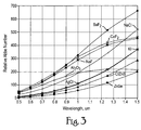
- Figure 3 shows a more detailed view of the plot shown in Figure 2 for wavelengths of light from 0.5 to 1.5 um;
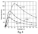
- Figure 4 shows a plot of relative Abbe numbers of NaF, BaF 2 and ClZnS for wavelengths of light from 0.5 to 10.5 um;
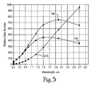
- Figure 5 shows a more detailed view of the plot shown in Figure 4 for wavelengths from 0.5 to 3.0 um;
- Figure 6 shows a raytrace schematic of an optical assembly according to an embodiment.
- Various factors for selecting one or more candidate materials for transmission of light were considered. These factors included, but were not necessarily limited to: the transmission characteristics of light in a medium, the refractive index of the material, the rate of change of refractive index, the Abbe number, the softness of material, the hydroscopic nature of the material (i.e., taking up and retaining moisture); the solubility of the material, the cost and availability of the material, and/or the size of the material. Some materials that are transparent over the desired portion of the spectra, for instance, may not be practical do to their physical properties (softness, solubility, etc.) or costs and availability.
- the relative Abbe number is a measure of a material's dispersion (i.e., variation of refractive index with wavelength) in relation to the refractive index.
- the general expression for relative Abbe Number may be determined according to equation (1) as follows:
- n avg is the refractive index of the material at the average (or midpoint) wavelength of the operating band of the material; n lower is the refractive index of the material at the lower wavelength of the operating band of the material; and n upper is the refractive index of the material at the upper wavelength of the operating band of the material.
- n lower is approximately n upper , then denominator will be small and the relative Abbe number is large or crown-like.
- An optical flint material may be characterized by having high dispersion and high refractive index and low Abbe numbers of less than about 50.
- an optical crown material may be characterized by having low dispersion and low refractive index and high Abbe numbers in excess of 50, for instance, 500.
- lR optical materials have smaller Abbe numbers than optical glass used for the flints, and higher Abbe numbers than optical glass for the crowns.
- a number of materials that were considered by the inventor include: barium fluoride (BaF 2 ), strontium titanate (SrTiO 3 ) sodium fluoride (NaF), spinel (MgAl 2 O 4 ), magnesium oxide (MgO), sapphire/aluminum oxide (Al 2 O 3 ), calcium fluoride (CaF 2 ), silver chloride (AgCl), Gallium arsenide (GaAs), cadmium telluride (CdTe), arsenic sulfide (As 2 S 3 ), AMTIR-1 Ge 33 As 12 Se 55 glass, zinc selenide (ZnSe), zinc sulfide (ZnS), silicon (Si), germanium (Ge), KRs-5 thallium bromoiodide glass, aluminum oxynitride (AION), sodium chloride (NaCl), potassium (K), potassium iodide (Kl), cesium bromide (CsBr), cesium io
- Table 2 shows the solubility of various materials in water. Table 2. Material Solubility in water Material Solubility (g/100 ml of water) Al 2 O 3 0 CaF 2 0.002 BaF 2 0.2 ClZnS 0 NaF 4 NaCl 36 ZnSe 0 AgCl 0.0005 Kl 128 CsBr 124 Csl 44 KBr 53 KCl 35
- Thallium bromoiodide (KRS-5) and others were also excluded for being too soft. Some materials, such as NaCl and others were excluded for being too hydroscopic for use in an optical assembly, such as a telescope. After excluding a number of materials, a few materials remained.
- Figure 2 shows a plot of various materials and their relative Abbe number for wavelengths of light from 0.5 to 10.5 um.
- materials include: barium fluoride (BaF 2 ), sodium fluoride (NaF), clear transient zinc sulfide (ClZnS), calcium fluoride (CaF 2 ), silver chloride (AgCl), zinc selenide (ZnSe) and particularly, clear zinc sulfide (ClZnS), aluminum oxide (Al 2 O 3 ), sodium chloride (NaCl), and potassium (K).
- Sapphire Al 2 O 3
- calcium fluoride CaF 2
- Sapphire Al 2 O 3
- lR optical materials exhibit this behavior in the vicinity of an absorption band.
- CaF 2 calcium fluoride
- NaF sodium fluoride
- Figure 3 shows a more detailed view of the plot shown in Figure 2 for wavelengths of light from 0.5 to 1.5 um. As more clearly shown, CaF 2 and NaF continue to show remarkably similar dispersion behavior down through the visible spectrum (i.e., less than about 0.7 um).
- an optical assembly is configured to be transparent to light and function in the visible, mid-wavelength infrared (MWIR) and long-wavelength infrared (LWIR) regions of the electromagnetic spectrum.
- the lens arrangement includes three types of materials with different dispersion characteristics.
- the disclosed optical assemblies eliminate the need for typical optical materials, such as, for example, calcium fluoride (CaF 2 ) and sapphire (Al 2 O 3 ) which are unsuitable for LWIR transmission having wavelengths of about 8-15 um.
- three materials may be used for fabricating an optical assembly. These materials include: barium fluoride (BaF 2 ) as the basic crown or low dispersion material, sodium fluoride (NaF) as the primary or basic flint or high dispersion material, and zinc sulfide (ZnS) and, particularly, clear transient ClearTran zinc sulfide (ClZnS) as a secondary or supplemental flint material for additional color correction, especially for the spectrum below 1 um.
- barium fluoride BaF 2
- NaF sodium fluoride
- ZnS zinc sulfide
- ClZnS clear transient ClearTran zinc sulfide
- Figure 4 shows a plot of relative Abbe numbers of NaF, BaF 2 and ClZnS for wavelengths of light from about 0.5 to 10.5 um. From about 1.8 to 10.5 um, BaF 2 and NaF maintain consistent crown and flint relationships and functions, respectively, over most of the spectral region of interest (except for the region below 1 um).
- Figure 5 shows a more detailed view of the plot shown in Figure 4 for wavelengths from about 0.5 to 3.0 um.
- BaF 2 and NaF become very similar in dispersion to effectively form an achromatic pair.
- ClZnS is more dispersive (flint-like) than NaF below 1.8 um, and assumes the flint role at these shorter wavelengths.
- ClZnS is considerably less dispersive (crown-like) than BaF 2 and therefore contributes very little to color correction.
- Clear transient zinc sulfide may be sold as "water-clear” zinc sulfide or "water-pure” zinc sulfide, for instance, under the trademarks Cleantran® and lrtran®.
- ClZnS functions to provide dispersion in this region from about 0.5 um to 1.0 um. At about 0.5 um, the Abbe number of ClZnS is approximately 11. After about 1.0 um, ClZnS has very crownish Abbe number (i.e., in excess of 500, for instance, at 4.5 um), and that material is no longer involved in the color correction. This is beneficial to the overall optical assembly because, after about 1.5 um, BaF 2 and NaF have a significant Abbe number difference (e.g., the Abbe difference is about 50-100).
- Figure 6 shows a raytrace schematic of optical assembly 600 according to an embodiment.
- Optical assembly 600 may include first lens 610 , second lens 620 , third lens 630 , fourth lens 640 , fifth lens 650 , and sixth lens 660 .
- First through third lenses 610-630 may be arranged to form an objective, while fourth through sixth lenses 640-660 may be arranged to form an eyepiece.
- a housing (not shown) may be provided to support the various lens elements, as known in the art.
- optical assembly 600 may be approximately 4.0 inches in length and 1.0 inches in diameter.
- light rays 601 in space 605 pass through first lens 610 , space 615 , second lens 620 , space 625 , third lens 630 , space 635 , fourth lens 640 , space 645 , fifth lens 650 , space 655 , sixth lens 660 , to space 665 .
- optical assembly 600 causes the focal plane array (FPA) to achieve a greater field of view (FOV), but through a smaller aperture.
- FPA focal plane array
- an afocal telescope does not have an intermediate image (or final image). Rather, collimated light enters the telescope, and collimated light exits the telescope.
- the telescope of an embodiment is Galilean in that there is no intermediate image, as opposed to Newtonian telescopes which have intermediate images. Newtonian telescopes have real exit pupils while Galilean telescopes do not have real exit pupils.
- Optical assembly 600 may be configured, for instance as shown, as a wide-field of view (WFOV) Galilean afocal telescope or attachment, for use in a helicopter targeting turret system (or similar system).
- WFOV wide-field of view
- Galilean afocal telescope or attachment for use in a helicopter targeting turret system (or similar system).
- the afocal Galilean telescope may include: an objective assembly having a secondary flint lens 610 comprised of zinc sulfide (ZnS); a positive-power crown lens 620 comprised of barium fluoride (BaF 2 ); and a negative-power primary flint lens 630 comprised of sodium fluoride (NaF); and an eyepiece assembly having a positive-power primary flint lens 640 comprised of sodium fluoride (NaF); a negative-power crown lens 650 comprised of barium fluoride (BaF 2 ); and a secondary flint lens 660 comprised of zinc sulfide (ZnS).
- ZnS zinc sulfide
- ZnS zinc sulfide
- ZnS zinc sulfide
- the ClZnS lenses i.e., first and sixth lenses 610, 660
- the two ClZnS lenses, 610 , 660 - being positioned on the outsides of the optical assembly 600 ⁇ also provide environmental protection for the BaF 2 and NaF lenses, i.e., second through fifth lenses 620-650 , that are internal to optical assembly 600 .
- Table 3 shows one example optical prescription for an embodiment of optical assembly 600 .
- the afocal magnification is approximately 4X, by taking an aperture of 0.660 inches and a FOV of 9.4 degrees in object space, and converting it into an aperture of 0.164 inches (4X smaller) and FOV of 36.6 degrees (4X larger).
- Optical assembly 600 is designed in the direction shown in the table, but is actually used in the reverse : the smaller aperture and wider FOV faces object space, while the larger aperture and smaller FOV is on the FPA side of the optics path. Between this afocal attachment and the FPA there may be an imager optics (not shown).
- Optical assembly 600 may be configured to transmit wavelengths of light from about 0.48 um to 10.6 um, or approximately 22 octaves. This provides transmission in not only the visible and MWIR spectra, but also in the LWIR spectra, a dramatic improvement over conventional approaches.
- Table 3 shows an optical prescription for the optical assembly 600 shown in Figure 6 , according to an embodiment.
- TABLE 3. PRESCRIPTION FOR VISIBLE, MWIR, AND LWIR AFOCAL TELESCOPE Surface Radius Thickness Material CC Ad Ae Af Ag 605 inf 1.570 air 610 -10.946 0.100 ClZnS 615 -20.594 0.010 air 1.498E-02 -8 515E-02 0.4131 -1.0145 620 1.312 0.260 BaF 2 625 -1.951 0.01 air -4 4568 -3.268E-02 0.1917 -0 7185 1.8735 630 -2.366 0.100 NaF 635 1.525 2.504 air 640 0.911 0.340 NaF 645 -0.836 0.006 air 650 -0.381 0.100 BaF 2 -2.0045 0.2676 -2565 2.9145 1.7094 655 0.676 0.192 air 660 1.435 0.100 ClZnS -0.1895 0.4509 1862 -5.429 6
- lens elements may be different types, sizes, and/or configurations.
- optical assembly 600 could be used in a reversed configuration.
- the conventional wide-field of view (WFOV) Galilean afocal telescope such as optical assembly 100 ( FIG. 1 ) used in a helicopter targeting turret system (or similar system) may be replaced with an optical assembly according to the present disclosure.
- WFOV wide-field of view
- Galilean afocal telescope such as optical assembly 100 ( FIG. 1 ) used in a helicopter targeting turret system (or similar system) may be replaced with an optical assembly according to the present disclosure.
- a vehicle and/or system including the conventional wide-field of view (WFOV) Galilean afocal telescope, such as optical assembly 100 ( FIG. 1 ), may be taken into service.
- WFOV wide-field of view
- One or more service centers may be provided, which include specialized equipment and personnel for serving these systems.
- the services centers may be located on military bases, government installations, and/or on premises that are owned or operated by defense contractors. Moreover, these service centers may provide other services and repairs for the vehicles or systems which utilize these optical assemblies.
- the conventional telescope assembly may be removed.
- various fasteners, connectors, harnesses, etc. may need to be released and/or removed to provide access to the telescope.
- the removed telescope units may be discarded or dismantled for recycling the components thereof.
- an optical assembly according to one or more disclosed embodiments such as optical assembly 600 , may be installed in the targeting turret system. This may require reassembling the various fasteners, connectors, harnesses, etc. to retain the newly installed telescope.
- the vehicle or system may then be returned to duty.
- Other systems which utilized optical systems and telescope may similarly be serviced or refurbished. Accordingly, the optical system provides a form, fit and function replacement to the conventionally known and potentially obsolete telescopes used in service.
- optical assembly 600 may be simpler in construction than conventional optical assembly 100 . ln fact, optical assembly 600 includes one fewer lens element than conventional optical assembly 100 .
Landscapes
- Physics & Mathematics (AREA)
- Optics & Photonics (AREA)
- General Physics & Mathematics (AREA)
- Engineering & Computer Science (AREA)
- General Engineering & Computer Science (AREA)
- Health & Medical Sciences (AREA)
- Toxicology (AREA)
- Chemical & Material Sciences (AREA)
- Crystallography & Structural Chemistry (AREA)
- Lenses (AREA)
Abstract
Description
- This invention was made with Government support from the Defense Microelectronics Activity under contract number H94003-04-D-0006. The U.S. Government may have certain rights in this invention.
- The application generally relates to optical elements, and in particular, materials and configuration for optical assemblies and telescopes.
- Refractive optics assemblies adapted for both the visible (approximately 400 ― 700 nm) and the mid-wavelength infrared (MWIR) (approximately 3-5 um) portions of the electromagnetic spectrum are known.
-
Figure 1 , for example, shows a raytrace schematic of a conventional optical assembly. Conventionaloptical assembly 100 may be configured as a wide-field of view (WFOV) Galilean afocal telescope as shown. One such attachment is used in the a helicopter targeting turret system. - Conventional
optical assembly 100 generally includesfirst lens 110,second lens 120,third lens 130,fourth lens 140,fifth lens 150,sixth lens 160 andseventh lens 170. First through fourth lenses 110-140 may be arranged to form an objective, while fifth to seventh lenses 150-170 may be arranged to form an eyepiece. A housing (not shown) is provided to support the various lens elements.Optical assembly 100 is approximately 4.0 inches in length and 1.0 inch in diameter. - In use,
light rays 101 inspace 105 pass throughfirst lens 110,space 115,second lens 120,space 125,third lens 130,space 135,fourth lens 140,space 145,fifth lens 150,space 155,sixth lens 160,space 165, andseventh lens 170 tospace 175. - Using
optical assembly 100 causes the focal plane array (FPA) to view more field of view (FOV), but through a smaller aperture. The afocal telescope does not have an intermediate image (or final image, for that matter). Rather, collimated light enters the telescope and collimated light exits the telescope. The telescope is Galilean in that there is no intermediate image, as opposed to Newtonian telescopes which have intermediate images. Newtonian telescopes have real exit pupils while Galilean telescopes do not have real exit pupils. - Table 1 shows one optical prescription for conventional
optical assembly 100. The afocal magnification is approximately 4X, by taking an aperture of 0.618 inches and FOV of 9.4 degrees in object space, and converting it into an aperture of 0.153 inches (4X smaller) and FOV of 38.14 degrees (4X larger). Conventionaloptical assembly 100 is designed in the direction shown in the table, but is actually used in the reverse, where the smaller aperture and wider FOV faces object space, while the larger aperture and smaller FOV is on the FPA side of the optics path. Between this afocal attachment and the FPA there may be imager optics (not shown).TABLE 1. PRESCRIPTION FOR CONVENTIONAL VISIBLE AND MWIR AFOCAL TELESCOPE Surface Radius Thickness Material CC Ad Ae Af Ag 105 Inf 2.300 Air 110 1.294 0.220 CaF2 115 -7.329 0.020 Air 120 3.018 0.130 CaF2 125 -26.161 0.177 Air 130 -56.896 0.100 ClZnS 135 23.696 0.041 Air 1.022E-02 -9.601E-03 0.14375 -0.29522 140 -3.679 0.100 Al203 145 5.468 2.226 Air 150 -0.515 0.100 BaF2 -1.24897 155 1 090 0018 Air 160 1.083 0.125 ClZnS -0.85156 6.024E-02 0.34278 -0.26262 -0.10652 165 1.226 0.019 Air 170 1.199 0.125 Al203 -1.98342 175 2.459 0.500 Air Entrance aperture: 0.660 diameter Entrance FOV: 9.4 deg total Spectral bands: 0.45 - 0.75 um, and 3.7 - 4.8 um Ad, Ae, Af, Ag are aspheric constants CC is a conic constant - As noted in Table 1,
optical assembly 100 is comprised of four materials: barium fluoride (BaF2), clear transient ClearTran zinc sulfide (ClZnS), calcium fluoride (CaF2), and aluminum oxide (Al2O3). In this assembly, Al2O3 is used as a crown and CaF2 is used a flint. At visible wavelengths, the ClZnS lens functions as a flint, and the CaF2, BaF2, and Al2O3 lenses function as crowns. However, at MWIR wavelengths, the Al2O3 lens functions as the flint, and the CaF2, BaF2, and ClZnS lenses function as crowns. The term crown generally refers to a low dispersion material, while the term flint generally refers to a high dispersion material. -
Optical assembly 100 is capable of transmitting wavelength from 0.48 um to 4.8 um, or about 10 octaves. However, this provides transmission in the visible and the MWIR spectra only. The optical system has been optimized to provide best image quality from about 0.45 to 0.75 microns and from 3.7 to 4.8 microns. - In addition, optics assemblies that transmit both the MWIR and long-wavelength infrared (LWlR) (approximately 8-12 um) portions of the spectrum are known. With the advent of 2-color (MWIR and LWIR) detector arrays, it is desired that certain optical assemblies also cover the visible and both the MWIR and the LWIR infrared bands.
- However, an optical assembly for achieving transmission in the visible, MWIR and LWlR portions of the electromagnetic spectrum has not yet been realized.
- In one embodiment, an optical lens assembly comprises: a first lens comprising a crown material; a second lens comprises a primary flint material for wavelengths below about 1.0 um; and a third lens comprising a secondary flint material for wavelengths below about 1.0 um, wherein the first, second and third lenses together are configured to transmit light and function in the visible, mid-wavelength infrared (MWIR) and long-wavelength infrared (LWIR) regions of the electromagnetic spectrum.
- In another embodiment, an afocal Galilean telescope comprises: a positive-power objective lens assembly comprising: a fist negative-power lens comprising a primary flint material; a second positive-power lens comprising a crown material; and a third negative-power lens comprising a secondary flint material; and a negative-power eyepiece lens assembly comprising: a fourth positive-power lens comprising a primary flint material; a fifth negative-power lens comprising a crown material; and a sixth positive-power lens secondary comprising a flint material, wherein the objective lens assembly and the eyepiece lens assembly together are arranged and configured to transmit light and function in the visible, mid-wavelength infrared (MWIR) and long-wavelength infrared (LWIR) regions of the electromagnetic spectrum.
- In yet another embodiment, a method of servicing a targeting turret system comprises: removing a telescope assembly from the targeting turret system; and installing an afocal Galilean telescope according to an embodiment in the targeting turret system.
- These and other aspects of this disclosure, as well as the methods of operation and functions of the related elements of structure and the combination of parts and economies of manufacture, will become more apparent upon consideration of the following description and the appended claims with reference to the accompanying drawings, all of which form a part of this specification, wherein like reference numerals designate corresponding parts in the various figures. It is to be expressly understood, however, that the drawings are for the purpose of illustration and description only and are not a limitation of the invention. In addition, it should be appreciated that structural features shown or described in any one embodiment herein can be used in other embodiments as well.
-
Figure 1 shows a raytrace schematic of a conventional optical assembly; -
Figure 2 shows a plot of various materials and their relative Abbe number for wavelengths of light from 0.5 to 10.5 um; -
Figure 3 shows a more detailed view of the plot shown inFigure 2 for wavelengths of light from 0.5 to 1.5 um; -
Figure 4 shows a plot of relative Abbe numbers of NaF, BaF2 and ClZnS for wavelengths of light from 0.5 to 10.5 um; -
Figure 5 shows a more detailed view of the plot shown inFigure 4 for wavelengths from 0.5 to 3.0 um; and -
Figure 6 shows a raytrace schematic of an optical assembly according to an embodiment. - Few optical materials have useful transmission characteristics in the broad spectral bandpass from about 0.5 um in the visible spectrum to about 11.0 um in the LWIR spectrum. The inventor thus endeavored to determine candidate materials which provide such transmission characteristics and to construct an optical assembly.
- Various factors for selecting one or more candidate materials for transmission of light were considered. These factors included, but were not necessarily limited to: the transmission characteristics of light in a medium, the refractive index of the material, the rate of change of refractive index, the Abbe number, the softness of material, the hydroscopic nature of the material (i.e., taking up and retaining moisture); the solubility of the material, the cost and availability of the material, and/or the size of the material. Some materials that are transparent over the desired portion of the spectra, for instance, may not be practical do to their physical properties (softness, solubility, etc.) or costs and availability.
- The relative Abbe number is a measure of a material's dispersion (i.e., variation of refractive index with wavelength) in relation to the refractive index. The general expression for relative Abbe Number may be determined according to equation (1) as follows:
-

- where,
navg is the refractive index of the material at the average (or midpoint) wavelength of the operating band of the material;
nlower is the refractive index of the material at the lower wavelength of the operating band of the material; and
nupper is the refractive index of the material at the upper wavelength of the operating band of the material. - If nlower is approximately nupper, then denominator will be small and the relative Abbe number is large or crown-like.
- An optical flint material may be characterized by having high dispersion and high refractive index and low Abbe numbers of less than about 50. On the other hand, an optical crown material may be characterized by having low dispersion and low refractive index and high Abbe numbers in excess of 50, for instance, 500. ln general, lR optical materials have smaller Abbe numbers than optical glass used for the flints, and higher Abbe numbers than optical glass for the crowns.
- A number of materials that were considered by the inventor include: barium fluoride (BaF2), strontium titanate (SrTiO3) sodium fluoride (NaF), spinel (MgAl2O4), magnesium oxide (MgO), sapphire/aluminum oxide (Al2O3), calcium fluoride (CaF2), silver chloride (AgCl), Gallium arsenide (GaAs), cadmium telluride (CdTe), arsenic sulfide (As2S3), AMTIR-1 Ge33As12Se55 glass, zinc selenide (ZnSe), zinc sulfide (ZnS), silicon (Si), germanium (Ge), KRs-5 thallium bromoiodide glass, aluminum oxynitride (AION), sodium chloride (NaCl), potassium (K), potassium iodide (Kl), cesium bromide (CsBr), cesium iodide (Csl), potassium bromide (KBr), and potassium chloride (KCI), and others.
- Table 2 shows the solubility of various materials in water.
Table 2. Material Solubility in water Material Solubility (g/100 ml of water) Al2O3 0 CaF2 0.002 BaF2 0.2 ClZnS 0 NaF 4 NaCl 36 ZnSe 0 AgCl 0.0005 Kl 128 CsBr 124 Csl 44 KBr 53 KCl 35 - Various materials were then excluded, such as NaCl, Kl, CsBr, Csl, KBr, and KCI, for being too soluble (i.e., being greater than 20-25 g/100 ml of water).
- Thallium bromoiodide (KRS-5) and others were also excluded for being too soft. Some materials, such as NaCl and others were excluded for being too hydroscopic for use in an optical assembly, such as a telescope. After excluding a number of materials, a few materials remained.
-
Figure 2 shows a plot of various materials and their relative Abbe number for wavelengths of light from 0.5 to 10.5 um. These materials include: barium fluoride (BaF2), sodium fluoride (NaF), clear transient zinc sulfide (ClZnS), calcium fluoride (CaF2), silver chloride (AgCl), zinc selenide (ZnSe) and particularly, clear zinc sulfide (ClZnS), aluminum oxide (Al2O3), sodium chloride (NaCl), and potassium (K). - Sapphire (Al2O3) and calcium fluoride (CaF2) are not useable past 5 and 7 um wavelengths, respectively. This is because these materials by their nature have an absorption band at those wavelengths, and thus, their transmission approaches zero. lR optical materials exhibit this behavior in the vicinity of an absorption band.
- On the other hand, calcium fluoride (CaF2) and sodium fluoride (NaF) are remarkably similar to each other in relative Abbe numbers at wavelengths below 7 um. Thus, NaF becomes a good replacement/substitute for CaF2 when LWIR performance is desired.
-
Figure 3 shows a more detailed view of the plot shown inFigure 2 for wavelengths of light from 0.5 to 1.5 um. As more clearly shown, CaF2 and NaF continue to show remarkably similar dispersion behavior down through the visible spectrum (i.e., less than about 0.7 um). - According to an aspect of this disclose, an optical assembly is configured to be transparent to light and function in the visible, mid-wavelength infrared (MWIR) and long-wavelength infrared (LWIR) regions of the electromagnetic spectrum. The lens arrangement includes three types of materials with different dispersion characteristics. The disclosed optical assemblies eliminate the need for typical optical materials, such as, for example, calcium fluoride (CaF2) and sapphire (Al2O3) which are unsuitable for LWIR transmission having wavelengths of about 8-15 um.
- In one embodiment, three materials may be used for fabricating an optical assembly. These materials include: barium fluoride (BaF2) as the basic crown or low dispersion material, sodium fluoride (NaF) as the primary or basic flint or high dispersion material, and zinc sulfide (ZnS) and, particularly, clear transient ClearTran zinc sulfide (ClZnS) as a secondary or supplemental flint material for additional color correction, especially for the spectrum below 1 um.
-
Figure 4 shows a plot of relative Abbe numbers of NaF, BaF2 and ClZnS for wavelengths of light from about 0.5 to 10.5 um. From about 1.8 to 10.5 um, BaF2 and NaF maintain consistent crown and flint relationships and functions, respectively, over most of the spectral region of interest (except for the region below 1 um). -
Figure 5 shows a more detailed view of the plot shown inFigure 4 for wavelengths from about 0.5 to 3.0 um. As more clearly shown, below about 1.5 um, BaF2 and NaF become very similar in dispersion to effectively form an achromatic pair. ClZnS, on the other hand, is more dispersive (flint-like) than NaF below 1.8 um, and assumes the flint role at these shorter wavelengths. At wavelengths greater than 2.3 um, ClZnS is considerably less dispersive (crown-like) than BaF2 and therefore contributes very little to color correction. - Clear transient zinc sulfide (ClZnS) may be sold as "water-clear" zinc sulfide or "water-pure" zinc sulfide, for instance, under the trademarks Cleantran® and lrtran®. ClZnS functions to provide dispersion in this region from about 0.5 um to 1.0 um. At about 0.5 um, the Abbe number of ClZnS is approximately 11. After about 1.0 um, ClZnS has very crownish Abbe number (i.e., in excess of 500, for instance, at 4.5 um), and that material is no longer involved in the color correction. This is beneficial to the overall optical assembly because, after about 1.5 um, BaF2 and NaF have a significant Abbe number difference (e.g., the Abbe difference is about 50-100).
-
Figure 6 shows a raytrace schematic ofoptical assembly 600 according to an embodiment.Optical assembly 600 may includefirst lens 610,second lens 620,third lens 630,fourth lens 640,fifth lens 650, andsixth lens 660. First through third lenses 610-630 may be arranged to form an objective, while fourth through sixth lenses 640-660 may be arranged to form an eyepiece. A housing (not shown) may be provided to support the various lens elements, as known in the art. In one implementation,optical assembly 600 may be approximately 4.0 inches in length and 1.0 inches in diameter. - In use,
light rays 601 inspace 605 pass throughfirst lens 610,space 615,second lens 620,space 625,third lens 630,space 635,fourth lens 640,space 645,fifth lens 650,space 655,sixth lens 660, tospace 665. - Using
optical assembly 600 causes the focal plane array (FPA) to achieve a greater field of view (FOV), but through a smaller aperture. As mentioned above, an afocal telescope does not have an intermediate image (or final image). Rather, collimated light enters the telescope, and collimated light exits the telescope. The telescope of an embodiment is Galilean in that there is no intermediate image, as opposed to Newtonian telescopes which have intermediate images. Newtonian telescopes have real exit pupils while Galilean telescopes do not have real exit pupils. -
Optical assembly 600 may be configured, for instance as shown, as a wide-field of view (WFOV) Galilean afocal telescope or attachment, for use in a helicopter targeting turret system (or similar system). - The afocal Galilean telescope may include: an objective assembly having a
secondary flint lens 610 comprised of zinc sulfide (ZnS); a positive-power crown lens 620 comprised of barium fluoride (BaF2); and a negative-powerprimary flint lens 630 comprised of sodium fluoride (NaF); and an eyepiece assembly having a positive-powerprimary flint lens 640 comprised of sodium fluoride (NaF); a negative-power crown lens 650 comprised of barium fluoride (BaF2); and asecondary flint lens 660 comprised of zinc sulfide (ZnS). - From the raytrace shown in
Figure 6 , it can be seen that the ClZnS lenses, i.e., first andsixth lenses optical assembly 600 ― also provide environmental protection for the BaF2 and NaF lenses, i.e., second through fifth lenses 620-650, that are internal tooptical assembly 600. - Table 3 shows one example optical prescription for an embodiment of
optical assembly 600. The afocal magnification is approximately 4X, by taking an aperture of 0.660 inches and a FOV of 9.4 degrees in object space, and converting it into an aperture of 0.164 inches (4X smaller) and FOV of 36.6 degrees (4X larger).Optical assembly 600 is designed in the direction shown in the table, but is actually used in the reverse : the smaller aperture and wider FOV faces object space, while the larger aperture and smaller FOV is on the FPA side of the optics path. Between this afocal attachment and the FPA there may be an imager optics (not shown). -
Optical assembly 600 may be configured to transmit wavelengths of light from about 0.48 um to 10.6 um, or approximately 22 octaves. This provides transmission in not only the visible and MWIR spectra, but also in the LWIR spectra, a dramatic improvement over conventional approaches. - Table 3 shows an optical prescription for the
optical assembly 600 shown inFigure 6 , according to an embodiment.TABLE 3. PRESCRIPTION FOR VISIBLE, MWIR, AND LWIR AFOCAL TELESCOPE Surface Radius Thickness Material CC Ad Ae Af Ag 605 inf 1.570 air 610 -10.946 0.100 ClZnS 615 -20.594 0.010 air 1.498E-02 -8 515E-02 0.4131 -1.0145 620 1.312 0.260 BaF2 625 -1.951 0.01 air -4 4568 -3.268E-02 0.1917 -0 7185 1.8735 630 -2.366 0.100 NaF 635 1.525 2.504 air 640 0.911 0.340 NaF 645 -0.836 0.006 air 650 -0.381 0.100 BaF2 -2.0045 0.2676 -2565 2.9145 1.7094 655 0.676 0.192 air 660 1.435 0.100 ClZnS -0.1895 0.4509 1862 -5.429 665 1.608 0.500 air Entrance aperture: 0.660 diameter Entrance FOV: 9.4 deg total Afocal magnification: 4.01X Spectral bands: 0.45 - 0.75 um, and 3.7 - 4.8 um, and 8.0 -10.6 um Ad, Ae, Af, Ag are aspheric constants CC is a conic constant - The particular lens types shown are not to be construed as limiting. It should be appreciated that, in other implementations, the lens elements may be different types, sizes, and/or configurations. For instance,
optical assembly 600 could be used in a reversed configuration. - According to a further embodiment, the conventional wide-field of view (WFOV) Galilean afocal telescope such as optical assembly 100 (
FIG. 1 ) used in a helicopter targeting turret system (or similar system) may be replaced with an optical assembly according to the present disclosure. - For instance, a vehicle and/or system including the conventional wide-field of view (WFOV) Galilean afocal telescope, such as optical assembly 100 (
FIG. 1 ), may be taken into service. One or more service centers may be provided, which include specialized equipment and personnel for serving these systems. The services centers may be located on military bases, government installations, and/or on premises that are owned or operated by defense contractors. Moreover, these service centers may provide other services and repairs for the vehicles or systems which utilize these optical assemblies. - The conventional telescope assembly may be removed. As will be appreciated, various fasteners, connectors, harnesses, etc. may need to be released and/or removed to provide access to the telescope. The removed telescope units may be discarded or dismantled for recycling the components thereof. Next, an optical assembly according to one or more disclosed embodiments, such as
optical assembly 600, may be installed in the targeting turret system. This may require reassembling the various fasteners, connectors, harnesses, etc. to retain the newly installed telescope. The vehicle or system may then be returned to duty. Other systems which utilized optical systems and telescope may similarly be serviced or refurbished. Accordingly, the optical system provides a form, fit and function replacement to the conventionally known and potentially obsolete telescopes used in service. - The optical assemblies disclosed according to one or more embodiments are advantageously configured for achieving transmission in the visible, MWIR and LWIR portions of the electromagnetic spectrum. Moreover,
optical assembly 600 may be simpler in construction than conventionaloptical assembly 100. ln fact,optical assembly 600 includes one fewer lens element than conventionaloptical assembly 100. - Other embodiments, uses and advantages of the inventive concept will be apparent to those skilled in the art from consideration of the above disclosure and the following claims. The specification should be considered non-limiting and exemplary only, and the scope of the inventive concept is accordingly intended to be limited only by the scope of the following claims.
Claims (15)
- An optical lens assembly comprising:a first lens comprising a crown material;a second lens comprises a primary flint material for wavelengths below about 1.0 um; anda third lens comprising a secondary flint material for wavelengths below about 1.0 um,wherein the first, second and third lenses together are configured to transmit light and function in the visible, mid-wavelength infrared (MWlR) and long-wavelength infrared (LWIR) regions of the electromagnetic spectrum.
- The optical lens assembly according to claim 1, wherein
the crown material comprises barium fluoride (BaF2);
the primary flint material comprises sodium fluoride (NaF); and
the secondary flint material comprises of zinc sulfide (ZnS). - The optical lens assembly according to claim 2, wherein the zinc sulfide (ZnS) comprises clear transient zinc sulfide (ClZnS).
- The optical lens assembly according to anyone of the previous claims, wherein the crown, the primary flint and the secondary flint are configured as an afocal Galilean telescope.
- The optical lens assembly according to claim 4, wherein the crown, the primary flint and the secondary flint are arranged as an objective lens assembly, an eyepiece lens assembly, or both.
- The optical lens assembly according to anyone of the previous claims, wherein the optical assembly is substantially transparent to wavelengths of light between about 0.5 and 11.0 um.
- The optical lens assembly according to anyone of the previous claims, wherein the length is approximately 4.0 inches and the width is approximately 1.0 inch is diameter.
- The optical lens assembly according to anyone of the previous claims, wherein the secondary flint is configured to provide color correction for wavelengths below about 1 um.
- An afocal Galilean telescope comprising:a positive-power objective lens assembly comprising:a fist negative-power lens comprising a primary flint material;a second positive-power lens comprising a crown material; anda third negative-power lens comprising a secondary flint material; anda negative-power eyepiece lens assembly comprising:a fourth positive-power lens comprising a primary flint material;a fifth negative-power lens comprising a crown material; anda sixth positive-power lens secondary comprising a flint material,wherein the objective lens assembly and the eyepiece lens assembly together are arranged and configured to transmit light and function in the visible, mid-wavelength infrared (MWIR) and long-wavelength infrared (LWIR) regions of the electromagnetic spectrum.
- The afocal Galilean telescope according to claim 9, wherein
one or both of the crown materials comprise barium fluoride (BaF2);
one or both of the primary flint materials comprise sodium fluoride (NaF); and one or both of the secondary flint materials comprise of zinc sulfide (ZnS). - The afocal Galilean telescope according to claim 10, wherein the zinc sulfide (ZnS) comprises clear transient zinc sulfide (ClZnS).
- The afocal Galilean telescope according to anyone of the claims 9 to 11, wherein the telescope assembly is substantially transparent to wavelengths of light between about 0.5 and 11.0 um.
- The afocal Galilean telescope according to anyone of the claims 9 to 12, wherein the length is approximately 4.0 inches and the diameter is approximately 1.0 inch.
- The afocal Galilean telescope according to anyone of the claims 9 to 13, wherein one or both of the secondary flint materials are configured to provide color correction for wavelengths below about 1 um.
- A method of servicing a targeting turret system comprising:removing a telescope assembly from the targeting turret system; andinstalling the afocal Galilean telescope according to anyone of the claims 9 to 14 into the targeting turret system.
Applications Claiming Priority (1)
| Application Number | Priority Date | Filing Date | Title |
|---|---|---|---|
| US12/635,853 US8902498B2 (en) | 2009-12-11 | 2009-12-11 | Broad spectral telescope |
Publications (2)
| Publication Number | Publication Date |
|---|---|
| EP2339387A1 true EP2339387A1 (en) | 2011-06-29 |
| EP2339387B1 EP2339387B1 (en) | 2014-08-27 |
Family
ID=43567574
Family Applications (1)
| Application Number | Title | Priority Date | Filing Date |
|---|---|---|---|
| EP10290548.6A Active EP2339387B1 (en) | 2009-12-11 | 2010-10-11 | Broad spectral telescope |
Country Status (3)
| Country | Link |
|---|---|
| US (1) | US8902498B2 (en) |
| EP (1) | EP2339387B1 (en) |
| IL (1) | IL208588A (en) |
Families Citing this family (7)
| Publication number | Priority date | Publication date | Assignee | Title |
|---|---|---|---|---|
| IL209332A (en) * | 2010-11-15 | 2016-10-31 | Opgal Optronic Ind Ltd | Optical arrangement usable for an ultra wide band optical sensor |
| US9244264B1 (en) | 2013-06-14 | 2016-01-26 | Sandia Corporation | Gimbaled multispectral imaging system and method |
| EP3191810A4 (en) * | 2014-09-09 | 2018-03-21 | The Government of the United States of America as represented by the Secretary of the Navy | Multispectral imaging system comprising new multispectral optics |
| CN113126286B (en) * | 2019-12-30 | 2025-03-21 | 电子科技大学中山学院 | An optimization method and structure of a Galilean telescope |
| US11268860B2 (en) | 2020-07-24 | 2022-03-08 | Raytheon Company | Radiometric calibration of detector |
| CN114089511B (en) * | 2021-11-26 | 2024-01-16 | 湖北久之洋红外系统股份有限公司 | Very wide band transmission type telescopic optical system |
| US12487106B1 (en) | 2022-08-10 | 2025-12-02 | National Technology & Engineering Solutions Of Sandia, Llc | Observer systems and methods |
Citations (2)
| Publication number | Priority date | Publication date | Assignee | Title |
|---|---|---|---|---|
| GB2206704A (en) * | 1987-06-27 | 1989-01-11 | Gec Avionics | Lens system |
| EP1355180A2 (en) * | 2002-04-19 | 2003-10-22 | Lockheed Martin Corporation | Refractive multispectral objective lens system and methods of selecting optical materials therefor |
Family Cites Families (4)
| Publication number | Priority date | Publication date | Assignee | Title |
|---|---|---|---|---|
| DE4417888A1 (en) * | 1994-05-21 | 1995-11-23 | Steinheil Optronik Gmbh | Refractive broadband ir lens |
| US5781336A (en) * | 1995-11-28 | 1998-07-14 | Lockheed Martin Corporation | Method and system for multi-spectral imaging in the visible and infrared spectrums |
| JPH11149039A (en) * | 1997-11-18 | 1999-06-02 | Asahi Optical Co Ltd | Achromatic lens system |
| US7218444B2 (en) | 2004-05-03 | 2007-05-15 | Raytheon Company | Dual-band, dual-focal-length, relayed refractive imager |
-
2009
- 2009-12-11 US US12/635,853 patent/US8902498B2/en active Active
-
2010
- 2010-10-10 IL IL208588A patent/IL208588A/en active IP Right Grant
- 2010-10-11 EP EP10290548.6A patent/EP2339387B1/en active Active
Patent Citations (2)
| Publication number | Priority date | Publication date | Assignee | Title |
|---|---|---|---|---|
| GB2206704A (en) * | 1987-06-27 | 1989-01-11 | Gec Avionics | Lens system |
| EP1355180A2 (en) * | 2002-04-19 | 2003-10-22 | Lockheed Martin Corporation | Refractive multispectral objective lens system and methods of selecting optical materials therefor |
Non-Patent Citations (3)
| Title |
|---|
| JAMIESON T H: "Decade wide waveband optics", PROCEEDINGS OF THE SPIE - THE INTERNATIONAL SOCIETY FOR OPTICAL ENGINEERING SPIE-INT. SOC. OPT. ENG. USA, vol. 3482, 1998, pages 306 - 320, XP002623025, ISSN: 0277-786X * |
| JAMIESON, T.H.: "Ultrawide waveband optics", OPTICAL ENGINEERING, vol. 23, no. 2, 1984, pages 111 - 116, XP001655774 * |
| WALKER A C: "ACHROMATIC DOUBLETS FOR SIMULTANEOUS IMAGING OF IR (10.6-MU M) AND VISIBLE (0.6328-MU M) RADIATION", APPLIED OPTICS, OPTICAL SOCIETY OF AMERICA, US, vol. 20, no. 24, 1 December 1981 (1981-12-01), XP002047523, ISSN: 0003-6935, DOI: 10.1364/AO.20.004143 * |
Also Published As
| Publication number | Publication date |
|---|---|
| EP2339387B1 (en) | 2014-08-27 |
| IL208588A (en) | 2015-07-30 |
| US8902498B2 (en) | 2014-12-02 |
| US20110228383A1 (en) | 2011-09-22 |
| IL208588A0 (en) | 2011-02-28 |
Similar Documents
| Publication | Publication Date | Title |
|---|---|---|
| EP2339387B1 (en) | Broad spectral telescope | |
| US4989962A (en) | Dual band/dual FOV infrared telescope | |
| US9297987B2 (en) | Wide field athermalized orthoscopic lens system | |
| EP1446635B1 (en) | Lightweight laser designator ranger flir optics | |
| US8101918B1 (en) | Re-imaging infrared lenses | |
| RU2683820C2 (en) | Telescope and telescope array for use in spacecraft | |
| EP1355180B1 (en) | Refractive multispectral objective lens system and methods of selecting optical materials therefor | |
| EP4235250B1 (en) | Two-color very wide field of view refractive eyepiece-type optical form | |
| US20120275016A1 (en) | Achromatic visible to far infrared objective lens | |
| US8836794B2 (en) | Dual field of view multi-band optics | |
| EP2367041A1 (en) | Flat field schmidt telescope with extended field of view | |
| US5838489A (en) | Refractive broad band IR objective | |
| US20100033578A1 (en) | Compact dual-field ir2-ir3 imaging system | |
| US7369303B2 (en) | Dual band lens system incorporating molded chalcogenide | |
| WO2014077890A1 (en) | Refractive optics with broad spectral coverage | |
| US6423969B1 (en) | Dual infrared band objective lens | |
| CN103197407A (en) | Common optical path dual-band confocal plane zoom optical system | |
| US4921318A (en) | Lens systems | |
| US7280273B2 (en) | Method and system for simultaneously imaging in the near infrared and short wave infrared spectrums | |
| CN112882210B (en) | Non-refrigeration medium-long wave broadband confocal infrared optical system | |
| CN114089511B (en) | Very wide band transmission type telescopic optical system | |
| Wynne et al. | A low-dispersion survey spectrograph | |
| US9946053B1 (en) | System and method for providing SWIR-MWIR reimaging along a same optical path | |
| RU2331094C2 (en) | Apochromatic objective | |
| RU2798087C1 (en) | Mirror lens |
Legal Events
| Date | Code | Title | Description |
|---|---|---|---|
| PUAI | Public reference made under article 153(3) epc to a published international application that has entered the european phase |
Free format text: ORIGINAL CODE: 0009012 |
|
| AK | Designated contracting states |
Kind code of ref document: A1 Designated state(s): AL AT BE BG CH CY CZ DE DK EE ES FI FR GB GR HR HU IE IS IT LI LT LU LV MC MK MT NL NO PL PT RO RS SE SI SK SM TR |
|
| AX | Request for extension of the european patent |
Extension state: BA ME |
|
| 17P | Request for examination filed |
Effective date: 20111214 |
|
| RIC1 | Information provided on ipc code assigned before grant |
Ipc: F41A 23/24 20060101ALN20131203BHEP Ipc: G02B 13/14 20060101AFI20131203BHEP Ipc: F41G 1/393 20060101ALN20131203BHEP Ipc: G02B 1/02 20060101ALI20131203BHEP |
|
| RIC1 | Information provided on ipc code assigned before grant |
Ipc: G02B 13/14 20060101AFI20131213BHEP Ipc: G02B 1/02 20060101ALI20131213BHEP Ipc: F41G 1/393 20060101ALN20131213BHEP Ipc: F41A 23/24 20060101ALN20131213BHEP |
|
| GRAP | Despatch of communication of intention to grant a patent |
Free format text: ORIGINAL CODE: EPIDOSNIGR1 |
|
| INTG | Intention to grant announced |
Effective date: 20140327 |
|
| GRAS | Grant fee paid |
Free format text: ORIGINAL CODE: EPIDOSNIGR3 |
|
| GRAA | (expected) grant |
Free format text: ORIGINAL CODE: 0009210 |
|
| AK | Designated contracting states |
Kind code of ref document: B1 Designated state(s): AL AT BE BG CH CY CZ DE DK EE ES FI FR GB GR HR HU IE IS IT LI LT LU LV MC MK MT NL NO PL PT RO RS SE SI SK SM TR |
|
| REG | Reference to a national code |
Ref country code: GB Ref legal event code: FG4D |
|
| REG | Reference to a national code |
Ref country code: CH Ref legal event code: EP |
|
| REG | Reference to a national code |
Ref country code: AT Ref legal event code: REF Ref document number: 684786 Country of ref document: AT Kind code of ref document: T Effective date: 20140915 |
|
| REG | Reference to a national code |
Ref country code: IE Ref legal event code: FG4D |
|
| REG | Reference to a national code |
Ref country code: DE Ref legal event code: R096 Ref document number: 602010018527 Country of ref document: DE Effective date: 20141009 |
|
| REG | Reference to a national code |
Ref country code: AT Ref legal event code: MK05 Ref document number: 684786 Country of ref document: AT Kind code of ref document: T Effective date: 20140827 |
|
| REG | Reference to a national code |
Ref country code: LT Ref legal event code: MG4D |
|
| REG | Reference to a national code |
Ref country code: NL Ref legal event code: VDEP Effective date: 20140827 |
|
| PG25 | Lapsed in a contracting state [announced via postgrant information from national office to epo] |
Ref country code: PT Free format text: LAPSE BECAUSE OF FAILURE TO SUBMIT A TRANSLATION OF THE DESCRIPTION OR TO PAY THE FEE WITHIN THE PRESCRIBED TIME-LIMIT Effective date: 20141229 Ref country code: LT Free format text: LAPSE BECAUSE OF FAILURE TO SUBMIT A TRANSLATION OF THE DESCRIPTION OR TO PAY THE FEE WITHIN THE PRESCRIBED TIME-LIMIT Effective date: 20140827 Ref country code: GR Free format text: LAPSE BECAUSE OF FAILURE TO SUBMIT A TRANSLATION OF THE DESCRIPTION OR TO PAY THE FEE WITHIN THE PRESCRIBED TIME-LIMIT Effective date: 20141128 Ref country code: SE Free format text: LAPSE BECAUSE OF FAILURE TO SUBMIT A TRANSLATION OF THE DESCRIPTION OR TO PAY THE FEE WITHIN THE PRESCRIBED TIME-LIMIT Effective date: 20140827 Ref country code: NO Free format text: LAPSE BECAUSE OF FAILURE TO SUBMIT A TRANSLATION OF THE DESCRIPTION OR TO PAY THE FEE WITHIN THE PRESCRIBED TIME-LIMIT Effective date: 20141127 Ref country code: BG Free format text: LAPSE BECAUSE OF FAILURE TO SUBMIT A TRANSLATION OF THE DESCRIPTION OR TO PAY THE FEE WITHIN THE PRESCRIBED TIME-LIMIT Effective date: 20141127 Ref country code: ES Free format text: LAPSE BECAUSE OF FAILURE TO SUBMIT A TRANSLATION OF THE DESCRIPTION OR TO PAY THE FEE WITHIN THE PRESCRIBED TIME-LIMIT Effective date: 20140827 Ref country code: FI Free format text: LAPSE BECAUSE OF FAILURE TO SUBMIT A TRANSLATION OF THE DESCRIPTION OR TO PAY THE FEE WITHIN THE PRESCRIBED TIME-LIMIT Effective date: 20140827 |
|
| PG25 | Lapsed in a contracting state [announced via postgrant information from national office to epo] |
Ref country code: RS Free format text: LAPSE BECAUSE OF FAILURE TO SUBMIT A TRANSLATION OF THE DESCRIPTION OR TO PAY THE FEE WITHIN THE PRESCRIBED TIME-LIMIT Effective date: 20140827 Ref country code: CY Free format text: LAPSE BECAUSE OF FAILURE TO SUBMIT A TRANSLATION OF THE DESCRIPTION OR TO PAY THE FEE WITHIN THE PRESCRIBED TIME-LIMIT Effective date: 20140827 Ref country code: IS Free format text: LAPSE BECAUSE OF FAILURE TO SUBMIT A TRANSLATION OF THE DESCRIPTION OR TO PAY THE FEE WITHIN THE PRESCRIBED TIME-LIMIT Effective date: 20141227 Ref country code: LV Free format text: LAPSE BECAUSE OF FAILURE TO SUBMIT A TRANSLATION OF THE DESCRIPTION OR TO PAY THE FEE WITHIN THE PRESCRIBED TIME-LIMIT Effective date: 20140827 Ref country code: AT Free format text: LAPSE BECAUSE OF FAILURE TO SUBMIT A TRANSLATION OF THE DESCRIPTION OR TO PAY THE FEE WITHIN THE PRESCRIBED TIME-LIMIT Effective date: 20140827 Ref country code: HR Free format text: LAPSE BECAUSE OF FAILURE TO SUBMIT A TRANSLATION OF THE DESCRIPTION OR TO PAY THE FEE WITHIN THE PRESCRIBED TIME-LIMIT Effective date: 20140827 |
|
| PG25 | Lapsed in a contracting state [announced via postgrant information from national office to epo] |
Ref country code: NL Free format text: LAPSE BECAUSE OF FAILURE TO SUBMIT A TRANSLATION OF THE DESCRIPTION OR TO PAY THE FEE WITHIN THE PRESCRIBED TIME-LIMIT Effective date: 20140827 |
|
| PG25 | Lapsed in a contracting state [announced via postgrant information from national office to epo] |
Ref country code: CZ Free format text: LAPSE BECAUSE OF FAILURE TO SUBMIT A TRANSLATION OF THE DESCRIPTION OR TO PAY THE FEE WITHIN THE PRESCRIBED TIME-LIMIT Effective date: 20140827 Ref country code: RO Free format text: LAPSE BECAUSE OF FAILURE TO SUBMIT A TRANSLATION OF THE DESCRIPTION OR TO PAY THE FEE WITHIN THE PRESCRIBED TIME-LIMIT Effective date: 20140827 Ref country code: EE Free format text: LAPSE BECAUSE OF FAILURE TO SUBMIT A TRANSLATION OF THE DESCRIPTION OR TO PAY THE FEE WITHIN THE PRESCRIBED TIME-LIMIT Effective date: 20140827 Ref country code: DK Free format text: LAPSE BECAUSE OF FAILURE TO SUBMIT A TRANSLATION OF THE DESCRIPTION OR TO PAY THE FEE WITHIN THE PRESCRIBED TIME-LIMIT Effective date: 20140827 Ref country code: IT Free format text: LAPSE BECAUSE OF FAILURE TO SUBMIT A TRANSLATION OF THE DESCRIPTION OR TO PAY THE FEE WITHIN THE PRESCRIBED TIME-LIMIT Effective date: 20140827 Ref country code: SK Free format text: LAPSE BECAUSE OF FAILURE TO SUBMIT A TRANSLATION OF THE DESCRIPTION OR TO PAY THE FEE WITHIN THE PRESCRIBED TIME-LIMIT Effective date: 20140827 |
|
| REG | Reference to a national code |
Ref country code: DE Ref legal event code: R097 Ref document number: 602010018527 Country of ref document: DE |
|
| PG25 | Lapsed in a contracting state [announced via postgrant information from national office to epo] |
Ref country code: PL Free format text: LAPSE BECAUSE OF FAILURE TO SUBMIT A TRANSLATION OF THE DESCRIPTION OR TO PAY THE FEE WITHIN THE PRESCRIBED TIME-LIMIT Effective date: 20140827 Ref country code: MC Free format text: LAPSE BECAUSE OF FAILURE TO SUBMIT A TRANSLATION OF THE DESCRIPTION OR TO PAY THE FEE WITHIN THE PRESCRIBED TIME-LIMIT Effective date: 20140827 Ref country code: LU Free format text: LAPSE BECAUSE OF FAILURE TO SUBMIT A TRANSLATION OF THE DESCRIPTION OR TO PAY THE FEE WITHIN THE PRESCRIBED TIME-LIMIT Effective date: 20141011 |
|
| REG | Reference to a national code |
Ref country code: CH Ref legal event code: PL |
|
| PG25 | Lapsed in a contracting state [announced via postgrant information from national office to epo] |
Ref country code: BE Free format text: LAPSE BECAUSE OF NON-PAYMENT OF DUE FEES Effective date: 20141031 |
|
| PLBE | No opposition filed within time limit |
Free format text: ORIGINAL CODE: 0009261 |
|
| STAA | Information on the status of an ep patent application or granted ep patent |
Free format text: STATUS: NO OPPOSITION FILED WITHIN TIME LIMIT |
|
| REG | Reference to a national code |
Ref country code: IE Ref legal event code: MM4A |
|
| PG25 | Lapsed in a contracting state [announced via postgrant information from national office to epo] |
Ref country code: LI Free format text: LAPSE BECAUSE OF NON-PAYMENT OF DUE FEES Effective date: 20141031 Ref country code: CH Free format text: LAPSE BECAUSE OF NON-PAYMENT OF DUE FEES Effective date: 20141031 |
|
| 26N | No opposition filed |
Effective date: 20150528 |
|
| PG25 | Lapsed in a contracting state [announced via postgrant information from national office to epo] |
Ref country code: IE Free format text: LAPSE BECAUSE OF NON-PAYMENT OF DUE FEES Effective date: 20141011 |
|
| PG25 | Lapsed in a contracting state [announced via postgrant information from national office to epo] |
Ref country code: SI Free format text: LAPSE BECAUSE OF FAILURE TO SUBMIT A TRANSLATION OF THE DESCRIPTION OR TO PAY THE FEE WITHIN THE PRESCRIBED TIME-LIMIT Effective date: 20140827 |
|
| PG25 | Lapsed in a contracting state [announced via postgrant information from national office to epo] |
Ref country code: SM Free format text: LAPSE BECAUSE OF FAILURE TO SUBMIT A TRANSLATION OF THE DESCRIPTION OR TO PAY THE FEE WITHIN THE PRESCRIBED TIME-LIMIT Effective date: 20140827 |
|
| PG25 | Lapsed in a contracting state [announced via postgrant information from national office to epo] |
Ref country code: TR Free format text: LAPSE BECAUSE OF FAILURE TO SUBMIT A TRANSLATION OF THE DESCRIPTION OR TO PAY THE FEE WITHIN THE PRESCRIBED TIME-LIMIT Effective date: 20140827 Ref country code: HU Free format text: LAPSE BECAUSE OF FAILURE TO SUBMIT A TRANSLATION OF THE DESCRIPTION OR TO PAY THE FEE WITHIN THE PRESCRIBED TIME-LIMIT; INVALID AB INITIO Effective date: 20101011 Ref country code: BE Free format text: LAPSE BECAUSE OF FAILURE TO SUBMIT A TRANSLATION OF THE DESCRIPTION OR TO PAY THE FEE WITHIN THE PRESCRIBED TIME-LIMIT Effective date: 20140827 Ref country code: MT Free format text: LAPSE BECAUSE OF FAILURE TO SUBMIT A TRANSLATION OF THE DESCRIPTION OR TO PAY THE FEE WITHIN THE PRESCRIBED TIME-LIMIT Effective date: 20140827 |
|
| REG | Reference to a national code |
Ref country code: FR Ref legal event code: PLFP Year of fee payment: 7 |
|
| REG | Reference to a national code |
Ref country code: FR Ref legal event code: PLFP Year of fee payment: 8 |
|
| PG25 | Lapsed in a contracting state [announced via postgrant information from national office to epo] |
Ref country code: MK Free format text: LAPSE BECAUSE OF FAILURE TO SUBMIT A TRANSLATION OF THE DESCRIPTION OR TO PAY THE FEE WITHIN THE PRESCRIBED TIME-LIMIT Effective date: 20140827 |
|
| REG | Reference to a national code |
Ref country code: FR Ref legal event code: PLFP Year of fee payment: 9 |
|
| PG25 | Lapsed in a contracting state [announced via postgrant information from national office to epo] |
Ref country code: AL Free format text: LAPSE BECAUSE OF FAILURE TO SUBMIT A TRANSLATION OF THE DESCRIPTION OR TO PAY THE FEE WITHIN THE PRESCRIBED TIME-LIMIT Effective date: 20140827 |
|
| PGFP | Annual fee paid to national office [announced via postgrant information from national office to epo] |
Ref country code: GB Payment date: 20200930 Year of fee payment: 11 |
|
| PGFP | Annual fee paid to national office [announced via postgrant information from national office to epo] |
Ref country code: DE Payment date: 20200929 Year of fee payment: 11 |
|
| REG | Reference to a national code |
Ref country code: DE Ref legal event code: R119 Ref document number: 602010018527 Country of ref document: DE |
|
| GBPC | Gb: european patent ceased through non-payment of renewal fee |
Effective date: 20211011 |
|
| PG25 | Lapsed in a contracting state [announced via postgrant information from national office to epo] |
Ref country code: GB Free format text: LAPSE BECAUSE OF NON-PAYMENT OF DUE FEES Effective date: 20211011 Ref country code: DE Free format text: LAPSE BECAUSE OF NON-PAYMENT OF DUE FEES Effective date: 20220503 |
|
| P01 | Opt-out of the competence of the unified patent court (upc) registered |
Effective date: 20230530 |
|
| PGFP | Annual fee paid to national office [announced via postgrant information from national office to epo] |
Ref country code: FR Payment date: 20250924 Year of fee payment: 16 |