EP2339190A1 - Halteelement zur unverlierbaren Montage einer Schraube - Google Patents
Halteelement zur unverlierbaren Montage einer Schraube Download PDFInfo
- Publication number
- EP2339190A1 EP2339190A1 EP10014662A EP10014662A EP2339190A1 EP 2339190 A1 EP2339190 A1 EP 2339190A1 EP 10014662 A EP10014662 A EP 10014662A EP 10014662 A EP10014662 A EP 10014662A EP 2339190 A1 EP2339190 A1 EP 2339190A1
- Authority
- EP
- European Patent Office
- Prior art keywords
- holding element
- screw
- workpiece
- element according
- retaining element
- Prior art date
- Legal status (The legal status is an assumption and is not a legal conclusion. Google has not performed a legal analysis and makes no representation as to the accuracy of the status listed.)
- Granted
Links
Images
Classifications
-
- F—MECHANICAL ENGINEERING; LIGHTING; HEATING; WEAPONS; BLASTING
- F16—ENGINEERING ELEMENTS AND UNITS; GENERAL MEASURES FOR PRODUCING AND MAINTAINING EFFECTIVE FUNCTIONING OF MACHINES OR INSTALLATIONS; THERMAL INSULATION IN GENERAL
- F16B—DEVICES FOR FASTENING OR SECURING CONSTRUCTIONAL ELEMENTS OR MACHINE PARTS TOGETHER, e.g. NAILS, BOLTS, CIRCLIPS, CLAMPS, CLIPS OR WEDGES; JOINTS OR JOINTING
- F16B41/00—Measures against loss of bolts, nuts, or pins; Measures against unauthorised operation of bolts, nuts or pins
- F16B41/002—Measures against loss of bolts, nuts or pins
Definitions
- the invention relates to a retaining element for captive mounting a screw on a workpiece, in particular a printed circuit board.
- the DE 10 2005 045 316 A1 describes a space-saving arrangement for holding a captive connection element on a workpiece.
- a connecting element such as. Example, a screw
- a deformation component which has a body in the form of a hardened annular washer with a clamping surface.
- the workpiece clamping surface of the deformation component has at least one wedge-like deformation element, which is angled radially and axially outward.
- the diameter of the connecting element opening is reduced, so that a stop is generated.
- This acts to mechanically lock or secure a shaft portion of a connector within the connector aperture.
- the connecting element is a screw with a screw head, an adjoining shaft without thread and an adjoining threaded part.
- the diameter of the connecting member opening is reduced by the pressed-deformation member to a value smaller than the diameter of the threaded portion of the screw. The screw can not fall out of the connector opening.
- the workpiece must be made of a malleable or cold-deformable material at least in the region of the connecting element opening.
- the deformation component acts a high pressure load on the workpiece, which can lead to deformation or damage to the workpiece.
- the pressure load leads to changes in the conductor structure, so that no traces can be performed in the vicinity of the connecting element opening.
- the object of the present invention is thus to provide a space-saving, inexpensive and easy-to-mount holder for captive mounting screws that can be attached without pressure on a workpiece.
- the retaining elements according to the invention for captive mounting a screw on a workpiece has a disc-like shape and a recess with an inner contour, wherein the inner contour has at least one radially inwardly facing lugs, in which engages a thread of the screw.
- any commercially available screw can be screwed into the holding element according to the invention and z. B. be pre-assembled in this way.
- the holding element alone can be fixed only via an opening in the workpiece and screwed in a second assembly step, the screw and thus captive held on the workpiece. This allows automatic assembly of the workpiece and thus reduces assembly costs, especially if the workpiece is a printed circuit board.
- the clear width between the lugs of the inner contour is smaller than the outer diameter of the screw thread and larger than a core diameter or inner diameter of the screw.
- the nominal thickness of the retaining element is smaller than the pitch of the screw thread.
- the holding element advantageously has a solderable surface.
- a solderable coated board or circuit board can be automatically equipped with such holding elements and soldered. This results in a good conductive connection, which can serve as ground contact.
- a simple and inexpensive automatic Guaranteed mounting of the retaining elements and the screws need only be screwed into the pre-equipped retaining elements. Pre-assembled circuit boards can be transported or stored as desired without losing the screws.
- the at least one nose of the inner contour may be square or round shaped.
- the holding element has three to five lugs. In a holding elements with at least three lugs, the screw to be screwed in can be easily centered and offers even larger screw diameters sufficient support.
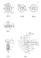
- Fig. 1a shows a first embodiment of a holding element according to the invention.
- the holding element has in this embodiment a circular outer contour 20 and a central recess 14.
- the inner contour 21 of the central recess 14 has two angular lugs 10, which point in the radial direction to the center 27 of the recess 14 and which are spaced from each other by the inside width 7.
- the inner contour 21 has a maximum width 6, which is greater than the clear width 7 between the lugs 10 and also larger than the outer diameter 8 of the thread 8 of the screw to be held 5.
- Fig. 1b shows a second embodiment of the holding element 1 'with three angular lugs 10th
- Fig. 1c represents a third embodiment of a holding element 1 "with now four round shaped lugs 10 '.
- the lugs 10, 10' lie in the plane of the holding element and are directed radially inwardly to the center 25 of the recess 24 of the holding member 5.
- Fig. 2 shows an embodiment of the support member 1 in side view with a view in the direction of arrow A.
- the support member 1 has a flat disc shape with a thickness 9.
- the surface 13 of the holding element is flat and at least on the workpiece-facing side with a solderable material, optionally in the form of a suitable surface coating, for. B. made of tin.
- the surface 13 of the holding element 5 is formed flat.
- a typical screw 5 is shown, which is to be mounted together with the holding element 1 captive on a workpiece 2.
- the screw 5 has a screw head 22, to which a threadless area 3 connects.
- the threadless region 3 is followed by an area with a thread 17, the an outer diameter 8 and a core diameter 15 has.
- Fig. 4 is now a detail view of the screw thread 17 screwed into the holding element 1 to see.
- the thread 17 of the screw has a thread 6 with a pitch 16, a flank angle 11 and an outer diameter 8.
- the suitable nominal thickness 9 of the holding element 1 is dependent on the flank angle 11 and the pitch 16 of the thread. In any case, the nominal thickness 9 of the retaining element 1 is smaller than the pitch 16 of the thread 17.
- the clear width 7 between the lugs 10 of the inner contour 21 has a value smaller than the outer diameter 8 of the thread, but larger than the core diameter 15 of the screw 5.
- the inside width 7 of the inner contour 21 is dimensioned such that the thread 17 of the screw 5 can be screwed into the retaining element 1 without significant effort.
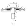
- Fig. 5 shows a screw 5, which is captively connected by the holding member 1 with the workpiece 2, for example, a circuit board.
- the holding element 1 is glued coaxially over the axis 23 of a bore 4 on the workpiece 2 and then soldered with a solder 18.
- a commercially available screw 5 is now screwed. After screwing in the complete thread 17 by the holding element 1, the screw 5 between the screw head 5 and thread 17 of the screw 5 is held captive by the holding element 1.
- the captivity of the screw 5 on the workpiece 2 results from the difference between the outer thread diameter 8 of the screw 5 and the clear width 7 of the support member 1, the difference between the outer diameter 27 of the screw head 22 and the clear width 7 of the support member 1, and the fixed connection between holding element 1 and workpiece 2.
- the holding element 5 according to the invention can be mounted automatically.
- the holding element 5 equipping machine, z. B. strapped and provided with adhesive dots executed. Due to the small nominal thickness 9 of the holding element 1 of typically 0.2-0.3 mm low height is achieved and requires little installation space.
- a captively mounted in this way screw is suitable, especially for multilayer boards, since the lamination of the individual layers is slightly damaged during the assembly of pressed-captive screws. Due to the low pressure force on the board surface, the tracks remain undamaged and can also be performed close to the support member.
- the outer contour of the holding element 1 can be selected only slightly larger than the bore 4 in the workpiece 2, so that surface for printed conductors can be obtained on the circuit board.
Landscapes
- Engineering & Computer Science (AREA)
- General Engineering & Computer Science (AREA)
- Mechanical Engineering (AREA)
- Mounting Of Printed Circuit Boards And The Like (AREA)
- Connection Of Plates (AREA)
Abstract
Description
- Die Erfindung bezieht sich auf ein Halteelement zur unverlierbaren Montage einer Schraube an einem Werkstück, insbesondere einer Leiterplatte.
- Um eine Schraube unverlierbar in einem Werkstück zu halten, ohne das Gewinde der Schraube in ein Gegengewinde einzudrehen, wird bislang beispielsweise eine Hülse, die mit einem Schraubenkopf fest verbunden ist in das Werkstück eingepresst oder eingenietet. Im Schraubenkopf ist eine Schraube integriert und drehbar sowie axial beweglich gelagert, so dass die Schraube auch im nicht im Gegengewinde eingedrehten Zustand fest mit dem Schraubenkopf und dem Werkstück verbunden ist. Durch Drehen der Schraube im Schraubenkopf wird die Schraube in das Gegengewinde eingeschraubt. Diese handelsüblichen unverlierbaren Schrauben weisen eine große Einbauhöhe auf. Unverlierbare Schrauben mit einem Durchmesser von 3 mm ragen typischerweise 1 bis 3 cm über das Werkstück hinaus. Dies erfordert ein großes Einbauvolumen und ist mit einem hohen Kostenaufwand verbunden.
- Die
DE 10 2005 045 316 A1 beschreibt eine platzsparende Anordnung zum Festhalten eines unverlierbaren Verbindungselements an einem Werkstück. Dabei durchgreift ein Verbindungselement, wie z. B. eine Schraube, ein Verformungsbauteil, das einen Körper in Form einer gehärteten ringförmigen Unterlagscheibe mit einer Klemmfläche besitzt. Die zum Werkstück zeigende Klemmfläche des Verformungsbauteils besitzt mindestens ein keilartiges Verformungselement, das radial und axial nach außen gewinkelt ist. Beim Eindrehen der Schraube wird das Verformungselement und damit die Klemmfläche gegen einen schmiedbaren bzw. kalt verformbaren Randabschnitt einer Öffnung im Werkstück gepresst, so dass das keilartige Verformungselement zumindest einen Abschnitt des Randes an der Verbindungselementöffnung verformt. Dabei wird der Durchmesser der Verbindungselementöffnung reduziert, sodass ein Anschlag erzeugt wird. Der wirkt dahingehend, einen Schaftabschnitt eines Verbindungselements innerhalb der Verbindungselementöffnung mechanisch festzuhalten bzw. zu sichern. Das Verbindungselement ist eine Schraube mit einem Schraubenkopf, einem daran anschließenden Schaft ohne Gewinde sowie einem daran anschließenden Gewindeteil. Somit so wird der Durchmesser der Verbindungselementöffnung durch das eingepresste Verformungsbauteil auf einen Wert der kleiner als der Durchmesser des Gewindebereichs der Schraube ist, reduziert. Die Schraube kann nicht mehr aus der Verbindungselementöffnung herausfallen. - Der Nachteil dieser Anordnung besteht darin, dass das Werkstück zumindest im Bereich der Verbindungselementöffnung aus einem schmiedbaren bzw. kalt verformbaren Material bestehen muss. Zudem wirkt beim Eindrehen des Verformungsbauteils eine hohe Druckbelastung auf das Werkstück, was zu Verformungen bzw. Beschädigungen des Werkstücks führen kann. Insbesondere beim Montieren dieser unverlierbaren Schraube auf eine Leiterplatte führt die Druckbelastung zu Veränderungen in der Leiterstruktur, so dass keine Leiterbahnen in näherer Umgebung der Verbindungselementöffnung geführt werden können.
- Die Aufgabe der vorliegenden Erfindung ist es somit, eine platzsparende, kostengünstige und einfach zu montierende Halterung zur unverlierbaren Montage von Schrauben zu schaffen, die ohne Druckeinwirkung an einem Werkstück angebracht werden können.
- Die Aufgabe wird durch das erfindungsgemäße Halteelement gemäß Anspruch 1 gelöst. In den Unteransprüchen sind vorteilhafte Weiterbildungen des erfindungsgemäßen Halteelements dargestellt.
- Das erfindungsgemäße Halteelemente zur unverlierbaren Montage einer Schraube an einem Werkstück besitzt eine scheibenartige Form und eine Ausnehmung mit einer Innenkontur, wobei die Innenkontur mindestens eine in radiale Richtung nach innen weisende Nasen aufweist, in die ein Gewinde der Schraube eingreift. Vorteilhafter Weise kann eine beliebige, handelsübliche Schraube in das erfindungsgemäße Halteelement eingeschraubt werden und z. B. in dieser Weise vormontiert werden. Andererseits kann das Halteelement alleine erst über eine Öffnung in dem Werkstück fixiert werden und in einem zweiten Montageschritt die Schraube eingedreht und damit unverlierbar am Werkstück gehalten werden. Dies ermöglicht eine automatische Bestückung des Werkstücks und senkt somit die Montagekosten, insbesondere wenn es sich bei dem Werkstück um eine Leiterplatte handelt.
- Vorteilhafterweise ist die lichte Weite zwischen den Nasen der Innenkontur kleiner als der Außendurchmesser des Schraubengewindes und größer als ein Kerndurchmesser bzw. Innendurchmesser der Schraube. Die Nenndicke des Halteelements ist kleiner als die Steigung des Schraubengewindes. Somit greift das Gewinde der Schraube in die Nasen der Innenkontur des Halteelements ein, ohne eine nennenswerte Krafteinwirkung auf das Halteelement oder das damit verbundene Werkstück auszuüben. Schrauben, die zwischen Schraubenkopf und Gewinde einen gewindefreien Bereich aufweisen, können sich nach dem Durchdrehen des Gewindeteils durch das Halteelement im gewindefreien Bereich der Schrauben nach allen Seiten eingeschränkt bewegt. Die Schraube wird im Bereich zwischen Schraubenkopf und Gewinde gehalten.
- Das Halteelement weist vorteilhafter Weise eine lötfähige Oberfläche auf. Eine lötfähig beschichtete Platine bzw. Leiterplatte kann mit solchen Halteelementen automatisch bestückt und verlötet werden. Dabei ergibt sich eine gut leitende Verbindung, die als Massekontakt dienen kann. Somit ist eine einfache und kostengünstige automatische Montage der Halteelemente gewährleistet und die Schrauben müssen lediglich in die vorbestückten Halteelemente eingeschraubt werden. In dieser Weise vormontierte Leiterplatten können beliebig transportiert oder gelagert werden, ohne die Schrauben zu verlieren.
- Die mindestens eine Nase der Innenkontur kann eckig oder auch rund ausgeformt sein. Besonders vorteilhaft weist das Halteelement drei bis fünf Nasen auf. In einem Halteelemente mit mindestens drei Nasen kann die einzudrehende Schraube einfach zentriert werden und bietet auch größeren Schraubendurchmessern ausreichend Halt.
- Ausführungsbeispiele des erfindungsgemäßen Halteelementes sind in der Zeichnung beispielhaft dargestellt und werden anhand der nachfolgenden Beschreibung näher erläutert. Es zeigen:
- Fig. 1a-c
- ein erstes, zweites und drittes Ausführungsbeispiel eines erfindungsgemäßen Halteelementes in Draufsicht;
- Fig. 2
- das erste Ausführungsbeispiel eines erfindungsgemäßen Halteelements in Seitenansicht mit Blickrichtung A;
- Fig. 3
- eine Schraube, die typischerweise mit einem erfindungsgemäßen Halteelement verbindbar ist;
- Fig. 4
- ein erfindungsgemäßes Halteelement eingedreht in ein Gewinde in Detailansicht und
- Fig. 5
- ein erfindungsgemäßes Halteelement mit Schraube montiert an einem Werkstück.
- Einander entsprechende Teile sind in allen Figuren mit den gleichen Bezugszeichen versehen.
-
Fig. 1a zeigt ein erstes Ausführungsbeispiel eines erfindungsgemäßen Halteelements. Das Halteelement weist in dieser Ausführungsform eine kreisförmige Außenkontur 20 sowie eine zentrale Ausnehmung 14 auf. Die Innenkontur 21 der zentralen Ausnehmung 14 weist zwei eckige Nasen 10 auf, die in radiale Richtung auf die Mitte 27 der Ausnehmung 14 zeigen und die durch die lichte Weite 7 voneinander beabstandet sind. Die Innenkontur 21 hat eine maximale Weite 6, die größer ist als die lichte Weite 7 zwischen den Nasen 10 und ebenfalls größer als der Außendurchmesser 8 des Gewindes 8 der zu haltenden Schraube 5 ist. -
Fig. 1b zeigt ein zweites Ausführungsbeispiel des Halteelements 1' mit drei eckigen Nasen 10.Fig. 1c stellt ein drittes Ausführungsbeispiel eines Halteelementes 1" mit nun vier rund ausgeformten Nasen 10' dar. Die Nasen 10, 10' liegen in der Ebene des Halteelements und sind radial nach innen auf die Mitte 25 der Ausnehmung 24 des Halteelements 5 gerichtet. -
Fig. 2 zeigt ein Ausführungsbeispiel des Halteelements 1 in Seitenansicht mit Blick in Pfeilrichtung A. Das Halteelement 1 weist eine flache Scheibenform mit einer Dicke 9 auf. Die Oberfläche 13 des Haltelements ist flach und mindestens an der dem Werkstück zugewandten Seite mit einem lötfähigem Material, ggf. in Form einer geeigneten Oberflächenbeschichtung, z. B. aus Zinn, versehen. Um einen guten Kontakt mit dem Werkstück 2 zu gewährleisten, ist die Oberfläche 13 des Haltelements 5 eben ausgebildet. - In
Fig. 3 ist eine typische Schraube 5 dargestellt, die mit dem Haltelement 1 zusammen unverlierbar an einem Werkstück 2 montiert werden soll. Die Schraube 5 weist einen Schraubenkopf 22 auf, an den ein gewindeloser Bereich 3 anschließt. An den gewindelosen Bereich 3 schließt sich ein Bereich mit einem Gewinde 17 an, das einen Außendurchmesser 8 und einen Kerndurchmesser 15 aufweist. - In
Fig. 4 ist nun eine Detailansicht des Schraubengewindes 17 eingedreht in das Haltelement 1 zu sehen. Das Gewinde 17 der Schraube hat einen Gewindegang 6 mit einer Steigung 16, einem Flankenwinkel 11 und einen Außendurchmesser 8. Die geeignete Nenndicke 9 des Halteelements 1 ist abhängig vom Flankenwinkel 11 und der Steigung 16 des Gewindes. In jedem Fall aber ist die Nenndicke 9 des Halteelements 1 kleiner als die Steigung 16 des Gewindes 17. Die lichte Weite 7 zwischen den Nasen 10 der Innenkontur 21 hat einen Wert kleiner als der Außendurchmesser 8 des Gewindes, aber größer als der Kerndurchmesser 15 der Schraube 5. Die lichte Weite 7 der Innenkontur 21 ist so bemessen, dass sich das Gewinde 17 der Schraube 5 ohne nennenswerten Kraftaufwand in das Halteelement 1 eindrehen lässt. -
Fig. 5 zeigt eine Schraube 5, die unverlierbar durch das Halteelement 1 mit dem Werkstück 2, beispielsweise einer Leiterplatte verbunden ist. Das Halteelement 1 wird koaxial über die Achse 23 einer Bohrung 4 auf dem Werkstück 2 aufgeklebt und anschließend mit einem Lötmittel 18 aufgelötet. In die mindestens eine Nase 10 des Haltelements 1 wird nun eine handelsübliche Schraube 5 eingedreht. Nach dem Eindrehen des vollständigen Gewindes 17 durch das Haltelement 1 wird die Schraube 5 zwischen Schraubenkopf 5 und Gewinde 17 der Schraube 5 unverlierbar durch das Halteelement 1 gehalten. Die Unverlierbarkeit der Schraube 5 am Werkstück 2 ergibt sich aus der Differenz zwischen dem Gewindeaußendurchmesser 8 der Schraube 5 und der lichten Weite 7 des Halteelements 1, der Differenz zwischen Außendurchmesser 27 des Schraubenkopfes 22 und der lichten Weite 7 des Halteelements 1, sowie der festen Verbindung zwischen Haltelement 1 und Werkstück 2. - Durch den Freiraum 24, siehe
Fig. 1a , in der Ausnehmung 14 kann das Gewinde 17 der Schraube 5 in das Haltelement 1 eingreifen, obwohl in das Haltelement 1 kein Gewinde eingebracht ist. Durch das fehlende Gewinde kann das Bauteil spanlos z. B. durch Lasern oder Stanzen gefertigt werden. Halteelemente 1 mit lötbarer Oberfläche 13 zur Bestückung von Platinen bestehen vorteilhafterweise aus Metall, insbesondere aus verzinntem Messing. - Das erfindungsgemäße Halteelement 5 kann automatisch montiert werden. Hierzu wird das Halteelement 5 bestückungsmaschinengerecht, z. B. gegurtet und mit Klebepunkten versehen, ausgeführt. Durch die geringe Nenndicke 9 des Halteelements 1 von typischerweise 0,2-0,3 mm wird eine geringe Bauhöhe erreicht und wenig Einbauraum benötigt.
- Beim Eindrehen der Schraube 5 in das Haltelement 1 wirken nur geringe physikalische Kräfte auf das Halteelement 1 selbst und auch auf das Werkstück 2 ein. Somit besteht kaum eine Gefahr der Beschädigung des Werkstücks 2 oder des Halteelements 1 selbst. Eine auf diese Weise unverlierbar montierte Schraube eignet sich, insbesondere für Multilayer-Platinen, da die Laminierung der einzelnen Schichten bei der Montage von eingepressten unverlierbaren Schrauben leicht beschädigt wird. Durch die geringe Druckkraft auf die Platinenoberfläche bleiben die Leiterbahnen unbeschädigt und können auch dicht am Halteelement geführt sein. Die Außenkontur des Haltelements 1 kann nur wenig größer als die Bohrung 4 im Werkstück 2 gewählt werden, so dass Fläche für Leiterbahnen auf der Leiterplatte gewonnen werden kann.
- Alle beschriebenen und/oder gezeichneten Merkmale können im Rahmen der Erfindung vorteilhaft miteinander kombiniert werden. Die Erfindung ist nicht auf die gezeigten Ausführungsbeispiele beschränkt. So kann z. B. die Außenkontur 20 des Haltelements 1 nicht nur rund, sondern auch rechteckig oder oval geformt sein.
Claims (11)
- Halteelement (1) zur unverlierbaren Montage einer Schraube (5) an einem Werkstück (2), wobei das Halteelement (1) eine scheibenartige Form aufweist und eine Ausnehmung (14) mit einer Innenkontur (21) besitzt,
dadurch gekennzeichnet,
dass die Innenkontur (21) mindestens eine in radiale Richtung nach innen weisende Nase (10) aufweist und die Innenkontur (21) in einen Gewindegang der Schraube eingreift. - Halteelement nach Anspruche 1,
dadurch gekennzeichnet,
dass die lichte Weite (7) zwischen der mindestens einen Nase (10) und der übrigen Innenkontur (21) des Halteelements (1) und/oder die lichte Weite (7) zwischen mindestens zwei Nasen (10) kleiner als der Außendurchmesser (8) des Schraubengewindes (17) und größer als der Kerndurchmesser (15) der Schraube (5) ist. - Halteelement nach Anspruch 1 oder 2,
dadurch gekennzeichnet,
dass eine Dicke des Halteelements (1) kleiner als die Steigung (16) des Schraubengewindes (17) ist. - Halteelement nach einem der Ansprüche 1 bis 3,
dadurch gekennzeichnet,
dass das Halteelement (1) eine lötfähige Oberfläche (13) aufweist. - Halteelement nach Anspruch 4,
dadurch gekennzeichnet,
dass das Halteelement (1) in der Umgebung einer Bohrung (4) des Werkstücks (2) aufgelötet ist. - Halteelement nach einem der Ansprüche 1 bis 5,
dadurch gekennzeichnet,
dass die mindestens eine Nase (10) eckig oder rund ausgeformt sind. - Halteelement nach einem der Ansprüche 1 bis 6,
dadurch gekennzeichnet,
dass die mindestens eine Nase (10) zum Zentrum der Ausnehmung (27) hin ausgerichtet sind. - Halteelement nach einem der Ansprüche 1 bis 7,
dadurch gekennzeichnet,
dass das Halteelement (1) drei bis fünf Nasen (10) aufweist. - Halteelement nach einem der Ansprüche 1 bis 8,
dadurch gekennzeichnet,
dass das Halteelement (1) aus einem lötfähigen Metall besteht und/oder eine verzinnte Oberfläche besitzt. - Halteelement nach einem der Ansprüche 1 bis 9,
dadurch gekennzeichnet,
dass das Halteelement (1) spanfrei durch Stanzen oder Laserschneiden hergestellt ist. - Halteelement nach einem der Ansprüche 1 bis 10,
dadurch gekennzeichnet,
dass das Werkstück (2) eine lötfähig beschichtete Leiterplatte ist.
Applications Claiming Priority (1)
| Application Number | Priority Date | Filing Date | Title |
|---|---|---|---|
| DE102009060060A DE102009060060A1 (de) | 2009-12-22 | 2009-12-22 | Halteelement zur unverlierbaren Montage einer Schraube |
Publications (2)
| Publication Number | Publication Date |
|---|---|
| EP2339190A1 true EP2339190A1 (de) | 2011-06-29 |
| EP2339190B1 EP2339190B1 (de) | 2014-06-04 |
Family
ID=43708850
Family Applications (1)
| Application Number | Title | Priority Date | Filing Date |
|---|---|---|---|
| EP10014662.0A Active EP2339190B1 (de) | 2009-12-22 | 2010-11-16 | Verfahren zur unverlierbaren Montage einer Schraube |
Country Status (2)
| Country | Link |
|---|---|
| EP (1) | EP2339190B1 (de) |
| DE (1) | DE102009060060A1 (de) |
Families Citing this family (1)
| Publication number | Priority date | Publication date | Assignee | Title |
|---|---|---|---|---|
| DE102016211857A1 (de) * | 2016-06-30 | 2018-01-04 | Bombardier Transportation Gmbh | Verbindungsanordnung mit Sicherungselement |
Citations (3)
| Publication number | Priority date | Publication date | Assignee | Title |
|---|---|---|---|---|
| FR875342A (fr) * | 1940-12-21 | 1942-09-16 | Focke Wulf Flugzeugbau Gmbh | Organe annulaire de blocage |
| US5750936A (en) * | 1996-10-29 | 1998-05-12 | Harris Corporation | Printed wiring board hardware captivation method |
| DE102005045316A1 (de) | 2004-09-27 | 2006-04-06 | General Motors Corp. (N.D.Ges.D. Staates Delaware), Detroit | Verformungsbauteil und Verfahren zum Festhalten eines unverlierbaren Verbindungselements |
Family Cites Families (4)
| Publication number | Priority date | Publication date | Assignee | Title |
|---|---|---|---|---|
| US2672069A (en) * | 1952-05-21 | 1954-03-16 | Mitchell Robert | Screw and washer assembly |
| WO1991005173A1 (en) * | 1989-09-29 | 1991-04-18 | Oz R & D Pty Limited | A self-locking washer |
| US5936846A (en) * | 1997-01-16 | 1999-08-10 | Ford Global Technologies | Optimized solder joints and lifter pads for improving the solder joint life of surface mount chips |
| GB2381300A (en) * | 2001-10-27 | 2003-04-30 | Rolls Royce Plc | Self-centring washer |
-
2009
- 2009-12-22 DE DE102009060060A patent/DE102009060060A1/de not_active Withdrawn
-
2010
- 2010-11-16 EP EP10014662.0A patent/EP2339190B1/de active Active
Patent Citations (3)
| Publication number | Priority date | Publication date | Assignee | Title |
|---|---|---|---|---|
| FR875342A (fr) * | 1940-12-21 | 1942-09-16 | Focke Wulf Flugzeugbau Gmbh | Organe annulaire de blocage |
| US5750936A (en) * | 1996-10-29 | 1998-05-12 | Harris Corporation | Printed wiring board hardware captivation method |
| DE102005045316A1 (de) | 2004-09-27 | 2006-04-06 | General Motors Corp. (N.D.Ges.D. Staates Delaware), Detroit | Verformungsbauteil und Verfahren zum Festhalten eines unverlierbaren Verbindungselements |
Also Published As
| Publication number | Publication date |
|---|---|
| EP2339190B1 (de) | 2014-06-04 |
| DE102009060060A1 (de) | 2011-06-30 |
Similar Documents
| Publication | Publication Date | Title |
|---|---|---|
| EP1696138B1 (de) | Toleranzausgleichsanordnung | |
| EP2244545B1 (de) | Elektrische Verbindungseinrichtung | |
| EP3159552B1 (de) | Spreiznietverbindung und verfahren zur montage derselben | |
| EP3889448B1 (de) | Befestigungselement | |
| DE102009038985A1 (de) | Schraubverbindung | |
| DE69501636T2 (de) | Einsatzmutter und Befestigungselement | |
| DE102010005833A1 (de) | Einlötkontaktanordnung | |
| WO2012130234A1 (de) | Elektrisch leitende schraubverbindung und spezial-buchse für eine solche schraubverbindung | |
| WO2011009440A1 (de) | Befestigungsvorrichtung und befestigungssystem | |
| EP1772633B1 (de) | Vorrichtung zum Verschrauben zweier Bauteile mit Toleranzausgleich | |
| EP2339190B1 (de) | Verfahren zur unverlierbaren Montage einer Schraube | |
| DE102009024335B4 (de) | Befestigungsschraube und ihre Verwendung und ein Verfahren zur Überwachung der Qualität der Schraubverbindung sowie eine Verbindungseinheit | |
| DE102007062359A1 (de) | Befestigungselement zur Befestigung eines Bauteils an einer Leiterplatte | |
| DE102023119845B3 (de) | Stromschiene-Steckkontaktpin-Verbindung | |
| DE102006010064A1 (de) | Aufnahme für Befestigungselement | |
| EP1612432B1 (de) | Befestigungsanordnung für eine Verkleidung und Befestigungsverfahren | |
| WO2020074256A1 (de) | Verfahren zum verbinden eines ersten bauteils mit einem zweiten bauteil | |
| EP0545158A1 (de) | Schraubeinrichtung | |
| DE102006040759B3 (de) | Toleranzausgleichsanordnung | |
| EP2088645B1 (de) | Befestigungssystem | |
| EP1897659A1 (de) | Verfahren zum Einbauen eines gewindepanzernden Elementes in ein Aufnahmegewinde sowie Einbauspindel und gewindepanzerndes Element hierfür | |
| EP3084860B1 (de) | Batterieklemme | |
| DE102022127873A1 (de) | Befestigungselement, Bauteilanordnung und Verfahren zum Befestigen eines ersten Bauteils und eines zweiten Bauteils aneinander mittels eines Befestigungselements | |
| DE102012215872A1 (de) | Ausfallsicherungselement sowie Anordnung und Verfahren zur unverlierbaren Montage einer Schraube an einem Kabelschuh | |
| DE102020203619B3 (de) | Montageset mit einem Kabelschuh und einer Schraubenmutter |
Legal Events
| Date | Code | Title | Description |
|---|---|---|---|
| PUAI | Public reference made under article 153(3) epc to a published international application that has entered the european phase |
Free format text: ORIGINAL CODE: 0009012 |
|
| 17P | Request for examination filed |
Effective date: 20110328 |
|
| AK | Designated contracting states |
Kind code of ref document: A1 Designated state(s): AL AT BE BG CH CY CZ DE DK EE ES FI FR GB GR HR HU IE IS IT LI LT LU LV MC MK MT NL NO PL PT RO RS SE SI SK SM TR |
|
| AX | Request for extension of the european patent |
Extension state: BA ME |
|
| 17Q | First examination report despatched |
Effective date: 20120724 |
|
| GRAJ | Information related to disapproval of communication of intention to grant by the applicant or resumption of examination proceedings by the epo deleted |
Free format text: ORIGINAL CODE: EPIDOSDIGR1 |
|
| GRAP | Despatch of communication of intention to grant a patent |
Free format text: ORIGINAL CODE: EPIDOSNIGR1 |
|
| GRAP | Despatch of communication of intention to grant a patent |
Free format text: ORIGINAL CODE: EPIDOSNIGR1 |
|
| INTG | Intention to grant announced |
Effective date: 20140107 |
|
| GRAS | Grant fee paid |
Free format text: ORIGINAL CODE: EPIDOSNIGR3 |
|
| GRAA | (expected) grant |
Free format text: ORIGINAL CODE: 0009210 |
|
| AK | Designated contracting states |
Kind code of ref document: B1 Designated state(s): AL AT BE BG CH CY CZ DE DK EE ES FI FR GB GR HR HU IE IS IT LI LT LU LV MC MK MT NL NO PL PT RO RS SE SI SK SM TR |
|
| REG | Reference to a national code |
Ref country code: GB Ref legal event code: FG4D Free format text: NOT ENGLISH |
|
| REG | Reference to a national code |
Ref country code: CH Ref legal event code: EP |
|
| REG | Reference to a national code |
Ref country code: AT Ref legal event code: REF Ref document number: 671249 Country of ref document: AT Kind code of ref document: T Effective date: 20140615 |
|
| REG | Reference to a national code |
Ref country code: IE Ref legal event code: FG4D Free format text: LANGUAGE OF EP DOCUMENT: GERMAN |
|
| REG | Reference to a national code |
Ref country code: DE Ref legal event code: R096 Ref document number: 502010007090 Country of ref document: DE Effective date: 20140717 |
|
| REG | Reference to a national code |
Ref country code: NL Ref legal event code: VDEP Effective date: 20140604 |
|
| PG25 | Lapsed in a contracting state [announced via postgrant information from national office to epo] |
Ref country code: NO Free format text: LAPSE BECAUSE OF FAILURE TO SUBMIT A TRANSLATION OF THE DESCRIPTION OR TO PAY THE FEE WITHIN THE PRESCRIBED TIME-LIMIT Effective date: 20140904 Ref country code: CY Free format text: LAPSE BECAUSE OF FAILURE TO SUBMIT A TRANSLATION OF THE DESCRIPTION OR TO PAY THE FEE WITHIN THE PRESCRIBED TIME-LIMIT Effective date: 20140604 Ref country code: FI Free format text: LAPSE BECAUSE OF FAILURE TO SUBMIT A TRANSLATION OF THE DESCRIPTION OR TO PAY THE FEE WITHIN THE PRESCRIBED TIME-LIMIT Effective date: 20140604 Ref country code: LT Free format text: LAPSE BECAUSE OF FAILURE TO SUBMIT A TRANSLATION OF THE DESCRIPTION OR TO PAY THE FEE WITHIN THE PRESCRIBED TIME-LIMIT Effective date: 20140604 Ref country code: GR Free format text: LAPSE BECAUSE OF FAILURE TO SUBMIT A TRANSLATION OF THE DESCRIPTION OR TO PAY THE FEE WITHIN THE PRESCRIBED TIME-LIMIT Effective date: 20140905 |
|
| REG | Reference to a national code |
Ref country code: LT Ref legal event code: MG4D |
|
| PG25 | Lapsed in a contracting state [announced via postgrant information from national office to epo] |
Ref country code: HR Free format text: LAPSE BECAUSE OF FAILURE TO SUBMIT A TRANSLATION OF THE DESCRIPTION OR TO PAY THE FEE WITHIN THE PRESCRIBED TIME-LIMIT Effective date: 20140604 Ref country code: SE Free format text: LAPSE BECAUSE OF FAILURE TO SUBMIT A TRANSLATION OF THE DESCRIPTION OR TO PAY THE FEE WITHIN THE PRESCRIBED TIME-LIMIT Effective date: 20140604 Ref country code: RS Free format text: LAPSE BECAUSE OF FAILURE TO SUBMIT A TRANSLATION OF THE DESCRIPTION OR TO PAY THE FEE WITHIN THE PRESCRIBED TIME-LIMIT Effective date: 20140604 Ref country code: LV Free format text: LAPSE BECAUSE OF FAILURE TO SUBMIT A TRANSLATION OF THE DESCRIPTION OR TO PAY THE FEE WITHIN THE PRESCRIBED TIME-LIMIT Effective date: 20140604 |
|
| PG25 | Lapsed in a contracting state [announced via postgrant information from national office to epo] |
Ref country code: EE Free format text: LAPSE BECAUSE OF FAILURE TO SUBMIT A TRANSLATION OF THE DESCRIPTION OR TO PAY THE FEE WITHIN THE PRESCRIBED TIME-LIMIT Effective date: 20140604 Ref country code: ES Free format text: LAPSE BECAUSE OF FAILURE TO SUBMIT A TRANSLATION OF THE DESCRIPTION OR TO PAY THE FEE WITHIN THE PRESCRIBED TIME-LIMIT Effective date: 20140604 Ref country code: CZ Free format text: LAPSE BECAUSE OF FAILURE TO SUBMIT A TRANSLATION OF THE DESCRIPTION OR TO PAY THE FEE WITHIN THE PRESCRIBED TIME-LIMIT Effective date: 20140604 Ref country code: RO Free format text: LAPSE BECAUSE OF FAILURE TO SUBMIT A TRANSLATION OF THE DESCRIPTION OR TO PAY THE FEE WITHIN THE PRESCRIBED TIME-LIMIT Effective date: 20140604 Ref country code: SK Free format text: LAPSE BECAUSE OF FAILURE TO SUBMIT A TRANSLATION OF THE DESCRIPTION OR TO PAY THE FEE WITHIN THE PRESCRIBED TIME-LIMIT Effective date: 20140604 Ref country code: PT Free format text: LAPSE BECAUSE OF FAILURE TO SUBMIT A TRANSLATION OF THE DESCRIPTION OR TO PAY THE FEE WITHIN THE PRESCRIBED TIME-LIMIT Effective date: 20141006 |
|
| PG25 | Lapsed in a contracting state [announced via postgrant information from national office to epo] |
Ref country code: PL Free format text: LAPSE BECAUSE OF FAILURE TO SUBMIT A TRANSLATION OF THE DESCRIPTION OR TO PAY THE FEE WITHIN THE PRESCRIBED TIME-LIMIT Effective date: 20140604 Ref country code: NL Free format text: LAPSE BECAUSE OF FAILURE TO SUBMIT A TRANSLATION OF THE DESCRIPTION OR TO PAY THE FEE WITHIN THE PRESCRIBED TIME-LIMIT Effective date: 20140604 Ref country code: IS Free format text: LAPSE BECAUSE OF FAILURE TO SUBMIT A TRANSLATION OF THE DESCRIPTION OR TO PAY THE FEE WITHIN THE PRESCRIBED TIME-LIMIT Effective date: 20141004 |
|
| REG | Reference to a national code |
Ref country code: DE Ref legal event code: R097 Ref document number: 502010007090 Country of ref document: DE |
|
| PLBE | No opposition filed within time limit |
Free format text: ORIGINAL CODE: 0009261 |
|
| STAA | Information on the status of an ep patent application or granted ep patent |
Free format text: STATUS: NO OPPOSITION FILED WITHIN TIME LIMIT |
|
| PG25 | Lapsed in a contracting state [announced via postgrant information from national office to epo] |
Ref country code: DK Free format text: LAPSE BECAUSE OF FAILURE TO SUBMIT A TRANSLATION OF THE DESCRIPTION OR TO PAY THE FEE WITHIN THE PRESCRIBED TIME-LIMIT Effective date: 20140604 |
|
| 26N | No opposition filed |
Effective date: 20150305 |
|
| REG | Reference to a national code |
Ref country code: DE Ref legal event code: R097 Ref document number: 502010007090 Country of ref document: DE Effective date: 20150305 |
|
| PG25 | Lapsed in a contracting state [announced via postgrant information from national office to epo] |
Ref country code: LU Free format text: LAPSE BECAUSE OF FAILURE TO SUBMIT A TRANSLATION OF THE DESCRIPTION OR TO PAY THE FEE WITHIN THE PRESCRIBED TIME-LIMIT Effective date: 20141116 Ref country code: BE Free format text: LAPSE BECAUSE OF NON-PAYMENT OF DUE FEES Effective date: 20141130 Ref country code: MC Free format text: LAPSE BECAUSE OF FAILURE TO SUBMIT A TRANSLATION OF THE DESCRIPTION OR TO PAY THE FEE WITHIN THE PRESCRIBED TIME-LIMIT Effective date: 20140604 |
|
| REG | Reference to a national code |
Ref country code: CH Ref legal event code: PL |
|
| PG25 | Lapsed in a contracting state [announced via postgrant information from national office to epo] |
Ref country code: SI Free format text: LAPSE BECAUSE OF FAILURE TO SUBMIT A TRANSLATION OF THE DESCRIPTION OR TO PAY THE FEE WITHIN THE PRESCRIBED TIME-LIMIT Effective date: 20140604 Ref country code: LI Free format text: LAPSE BECAUSE OF NON-PAYMENT OF DUE FEES Effective date: 20141130 Ref country code: CH Free format text: LAPSE BECAUSE OF NON-PAYMENT OF DUE FEES Effective date: 20141130 |
|
| REG | Reference to a national code |
Ref country code: IE Ref legal event code: MM4A |
|
| PG25 | Lapsed in a contracting state [announced via postgrant information from national office to epo] |
Ref country code: IE Free format text: LAPSE BECAUSE OF NON-PAYMENT OF DUE FEES Effective date: 20141116 |
|
| REG | Reference to a national code |
Ref country code: FR Ref legal event code: PLFP Year of fee payment: 6 |
|
| PG25 | Lapsed in a contracting state [announced via postgrant information from national office to epo] |
Ref country code: SM Free format text: LAPSE BECAUSE OF FAILURE TO SUBMIT A TRANSLATION OF THE DESCRIPTION OR TO PAY THE FEE WITHIN THE PRESCRIBED TIME-LIMIT Effective date: 20140604 |
|
| PG25 | Lapsed in a contracting state [announced via postgrant information from national office to epo] |
Ref country code: BG Free format text: LAPSE BECAUSE OF FAILURE TO SUBMIT A TRANSLATION OF THE DESCRIPTION OR TO PAY THE FEE WITHIN THE PRESCRIBED TIME-LIMIT Effective date: 20140604 |
|
| PG25 | Lapsed in a contracting state [announced via postgrant information from national office to epo] |
Ref country code: HU Free format text: LAPSE BECAUSE OF FAILURE TO SUBMIT A TRANSLATION OF THE DESCRIPTION OR TO PAY THE FEE WITHIN THE PRESCRIBED TIME-LIMIT; INVALID AB INITIO Effective date: 20101116 Ref country code: MT Free format text: LAPSE BECAUSE OF FAILURE TO SUBMIT A TRANSLATION OF THE DESCRIPTION OR TO PAY THE FEE WITHIN THE PRESCRIBED TIME-LIMIT Effective date: 20140604 Ref country code: TR Free format text: LAPSE BECAUSE OF FAILURE TO SUBMIT A TRANSLATION OF THE DESCRIPTION OR TO PAY THE FEE WITHIN THE PRESCRIBED TIME-LIMIT Effective date: 20140604 |
|
| REG | Reference to a national code |
Ref country code: FR Ref legal event code: PLFP Year of fee payment: 7 |
|
| REG | Reference to a national code |
Ref country code: AT Ref legal event code: MM01 Ref document number: 671249 Country of ref document: AT Kind code of ref document: T Effective date: 20151116 |
|
| PG25 | Lapsed in a contracting state [announced via postgrant information from national office to epo] |
Ref country code: AT Free format text: LAPSE BECAUSE OF NON-PAYMENT OF DUE FEES Effective date: 20151116 |
|
| REG | Reference to a national code |
Ref country code: FR Ref legal event code: PLFP Year of fee payment: 8 |
|
| PG25 | Lapsed in a contracting state [announced via postgrant information from national office to epo] |
Ref country code: MK Free format text: LAPSE BECAUSE OF FAILURE TO SUBMIT A TRANSLATION OF THE DESCRIPTION OR TO PAY THE FEE WITHIN THE PRESCRIBED TIME-LIMIT Effective date: 20140604 |
|
| PG25 | Lapsed in a contracting state [announced via postgrant information from national office to epo] |
Ref country code: AL Free format text: LAPSE BECAUSE OF FAILURE TO SUBMIT A TRANSLATION OF THE DESCRIPTION OR TO PAY THE FEE WITHIN THE PRESCRIBED TIME-LIMIT Effective date: 20140604 |
|
| P01 | Opt-out of the competence of the unified patent court (upc) registered |
Effective date: 20230525 |
|
| PGFP | Annual fee paid to national office [announced via postgrant information from national office to epo] |
Ref country code: DE Payment date: 20251118 Year of fee payment: 16 |
|
| PGFP | Annual fee paid to national office [announced via postgrant information from national office to epo] |
Ref country code: GB Payment date: 20251120 Year of fee payment: 16 |
|
| PGFP | Annual fee paid to national office [announced via postgrant information from national office to epo] |
Ref country code: IT Payment date: 20251128 Year of fee payment: 16 |
|
| PGFP | Annual fee paid to national office [announced via postgrant information from national office to epo] |
Ref country code: FR Payment date: 20251120 Year of fee payment: 16 |