EP2339144A2 - Heat exchanger mounting assembly in a gas turbine - Google Patents
Heat exchanger mounting assembly in a gas turbine Download PDFInfo
- Publication number
- EP2339144A2 EP2339144A2 EP10195796A EP10195796A EP2339144A2 EP 2339144 A2 EP2339144 A2 EP 2339144A2 EP 10195796 A EP10195796 A EP 10195796A EP 10195796 A EP10195796 A EP 10195796A EP 2339144 A2 EP2339144 A2 EP 2339144A2
- Authority
- EP
- European Patent Office
- Prior art keywords
- assembly
- bracket
- heat exchanger
- slip joint
- gas turbine
- Prior art date
- Legal status (The legal status is an assumption and is not a legal conclusion. Google has not performed a legal analysis and makes no representation as to the accuracy of the status listed.)
- Withdrawn
Links
Images


Classifications
-
- F—MECHANICAL ENGINEERING; LIGHTING; HEATING; WEAPONS; BLASTING
- F02—COMBUSTION ENGINES; HOT-GAS OR COMBUSTION-PRODUCT ENGINE PLANTS
- F02K—JET-PROPULSION PLANTS
- F02K3/00—Plants including a gas turbine driving a compressor or a ducted fan
- F02K3/02—Plants including a gas turbine driving a compressor or a ducted fan in which part of the working fluid by-passes the turbine and combustion chamber
- F02K3/04—Plants including a gas turbine driving a compressor or a ducted fan in which part of the working fluid by-passes the turbine and combustion chamber the plant including ducted fans, i.e. fans with high volume, low pressure outputs, for augmenting the jet thrust, e.g. of double-flow type
- F02K3/06—Plants including a gas turbine driving a compressor or a ducted fan in which part of the working fluid by-passes the turbine and combustion chamber the plant including ducted fans, i.e. fans with high volume, low pressure outputs, for augmenting the jet thrust, e.g. of double-flow type with front fan
-
- F—MECHANICAL ENGINEERING; LIGHTING; HEATING; WEAPONS; BLASTING
- F02—COMBUSTION ENGINES; HOT-GAS OR COMBUSTION-PRODUCT ENGINE PLANTS
- F02K—JET-PROPULSION PLANTS
- F02K1/00—Plants characterised by the form or arrangement of the jet pipe or nozzle; Jet pipes or nozzles peculiar thereto
- F02K1/78—Other construction of jet pipes
- F02K1/82—Jet pipe walls, e.g. liners
- F02K1/822—Heat insulating structures or liners, cooling arrangements, e.g. post combustion liners; Infra-red radiation suppressors
-
- Y—GENERAL TAGGING OF NEW TECHNOLOGICAL DEVELOPMENTS; GENERAL TAGGING OF CROSS-SECTIONAL TECHNOLOGIES SPANNING OVER SEVERAL SECTIONS OF THE IPC; TECHNICAL SUBJECTS COVERED BY FORMER USPC CROSS-REFERENCE ART COLLECTIONS [XRACs] AND DIGESTS
- Y02—TECHNOLOGIES OR APPLICATIONS FOR MITIGATION OR ADAPTATION AGAINST CLIMATE CHANGE
- Y02T—CLIMATE CHANGE MITIGATION TECHNOLOGIES RELATED TO TRANSPORTATION
- Y02T50/00—Aeronautics or air transport
- Y02T50/60—Efficient propulsion technologies, e.g. for aircraft
Definitions
- the field of this disclosure relates generally to a mounting assembly for mounting a heat exchanger in a gas turbine engine assembly, and more particularly to a mounting assembly including a slip joint to allow relative movement between a heat exchanger and a structural body of the gas turbine engine.
- radiators that are exposed to air flowing through the engine assembly to facilitate cooling a working fluid (e.g., an oil and/or a fuel) flowing through the radiator.
- a working fluid e.g., an oil and/or a fuel
- many gas turbine engine radiators have been known to obstruct airflow through the engine assembly, causing turbulence and/or pressure drops within the engine assembly, which could adversely affect engine performance. Additionally, interruption of the radiator with joint assemblies reduces the area available for cooling.
- At least some known gas turbine engine radiators are susceptible to high cycle fatigue (e.g., fatigue resulting from vibrations caused by rotor imbalance) and/or low cycle fatigue (e.g., fatigue resulting from thermal growth of the radiator caused by a temperature differential between the radiator and the supporting structure).
- Exemplary embodiments disclosed herein provide a mounting system for a heat exchanger that provides sufficient stiffness for vibrational high cycle fatigue mediation while relieving low cycle fatigue stress caused by thermal expansion.
- a heat exchanger assembly includes a first member comprising an arcuate body having a plurality of fins extending from a radial inner surface and a plurality of circumferentially extending spaced attachment sites defined on a radial outer surface.
- a bracket assembly is attached in supported connection with the first member by at least one of the attachment sites, wherein the bracket assembly is sized and configured for operable association with a slip joint assembly for supported attachment of the heat exchanger assembly to a structural body of a gas turbine assembly.
- a heat exchanger assembly includes a first member comprising an arcuate body having a plurality of fins extending from a radial inner surface and a plurality of circumferentially extending weld tabs defined on a radial outer surface.
- a bracket assembly includes a bracket having a base portion and first and second arm portions extending from the base portion to provide the bracket with a c-shaped cross section. Each of the first and second arm portions are fixedly secured to an associated weld tab such that the base portion is arranged in spaced relationship to the radial outer surface.
- the bracket includes an opening defined in the base portion being sized and configured for reception of an attachment member.
- the bracket assembly includes a fastener member extending in the space between the base portion and the radial outer surface proximate the opening.
- a heat exchanger support includes a bracket assembly including a bracket having a base portion and first and second arm portions extending from the base portion to provide the bracket with a c-shaped cross section and defining an interior region.
- the bracket includes an opening defined in the base portion and being sized and configured for reception of an attachment member.
- the bracket assembly includes a fastener member selectively secured to the bracket proximate the opening within the interior region.
- a heat exchanger assembly for a gas turbine engine and a mounting system
- the heat exchanger assembly includes a plurality of arcuate manifolds each supporting an array of fins extending from a radial inner surface.
- a plurality of circumferentially extending spaced weld tabs is integrally formed on the radial outer surface.
- a bracket assembly is utilized to attach the heat exchanger to a structural member of a gas turbine engine assembly, e.g., a fan case, in such a manner as to maximize the surface area available for fin placement, and to not interfere with the cooling circuits within the manifold.
- the mounting system provides adequate stiffness for high cycle fatigue loads (i.e., vibrations) and allows relative slippage between the heat exchanger and the fan case to accommodate thermal expansion and contraction to address low cycle fatigue loads.
- FIG 1 is a schematic illustration of an exemplary gas turbine engine assembly 500.
- Gas turbine engine assembly 500 has a centerline axis 502 and a radius R (shown in Figure 2 ) and includes an intake side 504, an exhaust side 506, a fan assembly 508, and a core gas turbine engine 510.
- Fan assembly 508 includes an array of fan blades 512 extending radially outward from a rotor disk 514 and positioned axially forward of a bypass duct 516 defined between a first duct surface 518 and a second duct surface 522.
- a heat exchanger assembly 600 is coupled to a fan case 520 axially aftward of fan assembly 508 such that heat exchanger assembly 600 is exposed to an airflow AF through bypass duct 516.
- a heat exchanger assembly 600 may be mounted at any suitable location on gas turbine engine assembly 500.
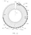
- FIG 2 is a side elevation view of an exemplary heat exchanger assembly 600 shown mounted in operational engagement with fan case 520.
- heat exchanger assembly 600 includes a plurality of substantially similar circumferentially extending heat exchangers 602.
- Each heat exchanger 602 has a first end 604, a second end 606, and a substantially arcuate body 608 extending between first end 604 and second end 606, such that heat exchanger 602 substantially conforms to a profile of bypass duct 516 (shown in Figure 1 ).
- Heat exchanger assembly 600 may have any suitable number of heat exchangers 602 having any suitable profile that enables heat exchanger assembly 600 to function as described herein.
- first end 604 may be fixedly coupled (e.g., bolted) to a fan case 520 and body 608 and second end 606 are slideably coupled to fan case 520 via a plurality of mounting systems 700, as described below.
- Each heat exchanger 602 may be coupled to fan case 520 via any suitable number of mounting systems 700. In an exemplary embodiment about 20 mounting systems 700 may be utilized for each heat exchanger 602.
- first end 604 includes an inlet port (not shown) and an outlet port (not shown) to facilitate coupling heat exchanger 602 to at least one fluid transfer line (not shown) and directing a flow of heated fluid through heat exchanger 602 to be cooled.
- heat exchanger assembly 600 is coupled to fan case 520 such that heat exchangers 602 are circumferentially spaced apart from one another (e.g., by at least .25 inches, for example).
- a faring substantially spans the space between adjacent heat exchangers 602 to facilitate a smoother flow of air over heat exchanger assembly 600.
- heat exchanger assembly 600 may be mounted at any suitable location on gas turbine engine assembly 500 using any suitable fasteners, such that heat exchangers 602 have any suitable orientation relative to one another.
- heat exchanger 602 includes a manifold 610 and a plurality of cooling fins 612 radially extending from manifold 610.
- Manifold 610 includes a radially inner surface 614, a radially outer surface 616, an upstream wall 618, and an opposite downstream wall 620, such that manifold 610 has a substantially rectangular cross-sectional profile.
- Manifold 610 defines at least one channel 622 that extends lengthwise therethrough and is selectively sized to facilitate channeling a flow of heated fluid (e.g., oil) to be cooled.
- each channel 622 has a substantially rectangular cross-sectional profile.
- manifold 610 and/or each channel 622 may have any suitable cross-sectional profile (e.g., circular).
- Heat exchanger 602 may include an integral manifold 610 and cooling fins 612 formed together via an aluminum extrusion process.
- each cooling fin 612 may be coupled to manifold 610 via a bonding process (e.g., a welding process or a brazing process) and/or formed as a non-segmented, unitary body.
- heat exchanger 602 may be fabricated via any suitable manufacturing process and/or from any suitable material.
- manifold 610 may have a plurality of circumferential integrally formed weld tabs 615 to facilitate mounting the heat exchangers onto the fan case.
- each mounting system 700 facilitates coupling heat exchanger 602 to fan case 520 at a slot 524 that extends substantially radially through a wall 560 of fan case 520.
- slot 524 has a first end 526 defined on a radially inner first surface 544 of wall 560, a second end 528 defined on a radially outer second surface 546 of wall 560, and a length SL (see Figure 4 ) extending from first end 526 to second end 528, such that slot 524 has an elongated cross-sectional profile (i.e., a major axis 530 and a minor axis 532; Figure 5 ).
- slot 524 may have any suitable shape and/or cross-sectional profile that enables mounting system 700 to function as described herein.
- anti-wear elements 534 are suitably coupled to wall 560 proximate to slot 524.
- an anti-wear element 534 includes a first portion 536 coupled to first surface 544 of wall 560 circumferentially about slot 524, a second portion 538 coupled to second surface 546 of wall 560 circumferentially about slot 524, and a third portion 540 coupled to an interior surface 542 of slot 524.
- second portion 538 and third portion 540 may be integrally formed together and separately from first portion 536.
- anti-wear element 534 may have any suitable number of portions that are either formed integrally together or formed separately from one another.
- a plurality of mounting systems 700 are utilized to mount the heat exchanger assemblies 600 to a structure in the gas turbine engine, for example, a fan case.
- the mounting systems 700 provide adequate stiffness to address vibrational concerns, while allowing for thermal expansion of the heat exchangers both axially and circumferentially.
- each mounting system 700 may include a bracket 702 and a slip joint 704 to facilitate coupling the heat exchanger 602 to the fan case 520 or other engine structure.
- Bracket 702 includes a fastener assembly 735 for receiving a bolt 738 of the slip joint 704.
- fastener assembly 735 includes a fixed nut plate 736 whereby attachment of the slip joint 704 to bracket 702 is accomplished by turning the bolt 738 rather than by tightening a nut, which may be accomplished from the outer diameter of fan case 520, as set forth in greater detail below.
- bracket 702 includes a first arm 706, a second arm 708, and a base 710 that extends between first arm 706 and second arm 708. In an exemplary embodiment, the length of bracket 702 is less than a width of manifold 610, as illustrated in Figure 3 .
- First arm 706 has a first length AL 1
- second arm 708 has a second length AL 2 .
- second length AL 2 may be greater than first length AL 1 if warranted by the particular application.
- bracket 702 is fixedly secured at the first arm 706 and the second arm 708 to spaced weld tabs 615.
- manifold 706 includes at least three continuous weld tabs 615 to accommodate the length of brackets 702.
- the continuous weld tabs allow for placement of brackets 702 at various positions along the manifold 706.
- brackets 702 are spaced unevenly along the length of the manifold 706 to minimize or prevent sinusoidal modes in the heat exchanger.
- the brackets allow for varied positions of the fastener assemblies 735 along the axial length of the brackets 702.
- manifold 706 may accommodate two circumferential rows of brackets 702 which may be offset relative each other.
- manifold 706 includes four continuous weld tabs 615.
- a spacer 716 (e.g., a steel spacer) may be coupled to a bottom face 718 of base 710 via at least one fastener (e.g., a rivet 720).
- slip mount 704 includes a retainer plate or washer 722, a standoff 724, and a biasing element 726 (e.g., wave spring).
- Standoff 724 includes a hollow elongated member or bushing 728, which has a length CL, and a flange 730 extending outwardly from elongated member 728.
- elongated member 728 functions to limit the movement of bolt 738 relative the bracket 702, and thus limits or preloads the compression of biasing element (wave spring) 726. The amount of compression of biasing element (wave spring) 726 influences the biasing force exerted by the slip joint onto fan case 520.
- the biasing force is sufficient to withstand vibrational forces, but less than thermal forces, herein referred to as "sliding forces.”
- sliding forces the joint will not move due to smaller vibration forces, but it will slide when the sliding force from thermal growth tendencies exceeds the preloaded biasing force.
- flange 730 includes a lip 760 to facilitate supporting biasing element 726 about elongated member 728.
- flange 730 is formed integrally with elongated member 728 and extends circumferentially outward from elongated member 728.
- Washer 722 and biasing element 726 are substantially annular such that elongated member 728 is insertable through biasing element 726 and/or washer 722, as described below.
- standoff 724, washer 722, and/or biasing element 726 may include any suitable structure and may be formed integrally together or separately from one another to enable mounting system 700 to function as described herein.
- mounting system 700 also includes a locking device 740 including a cap 742 seated against flange 730, a foot 744 either formed with or coupled to washer 722, and a link 746 (e.g., a cable) extending between foot 744 and cap 742 to facilitate holding biasing element 726 between washer 722 and flange 730.
- locking device 740 may include any suitable structure that enables locking device 740 to function as described herein.
- bracket 702 is positioned adjacent fan case 520 such that spacer 716 is seated against first portion 536 of anti-wear element 534 and such that manifold 610 is oriented at an angle ⁇ relative to base 710. In this way, radially inner surface 614 of manifold 610 is substantially aligned with a contour of first duct surface 518 such that only cooling fins 612 extend into bypass duct 516.
- upstream wall 618 and downstream wall 620 of manifold 610 are spaced from first duct surface 518 by a first gap G 1 and a second gap G 2 , respectively, to facilitate permitting manifold 610 to expand along centerline axis 502 when heated, as described below.
- a first seal 732 substantially covers first gap G 1
- a second seal 734 substantially covers second gap G 2 to facilitate blocking airflow through first gap G 1 and/or second gap G 2 during operation of gas turbine engine assembly 500.
- bracket 702 With bracket 702 positioned adjacent fan case 520, standoff 724 is inserted through slot 524 with biasing element 726 and washer 722 circumscribing elongated member 728 such that biasing element 726 is held between flange 730 and washer 722 via locking device 740.
- Locking device 740 is useful to facilitate easier handling of slip mount 704 with biasing element 726 and washer 722 positioned about elongated member 728.
- a bolt 738 is inserted through elongated member 728 such that bolt 738 engages a nut 736 and/or bracket 702 to facilitate fastening bracket 702 to fan case 520.
- a frictional engagement is thus established between spacer 716 and first portion 536 of anti-wear element 534 and between washer 722 and second portion 538 of anti-wear element 534.
- length CL of elongated member 728 is greater than length SL of slot 524 such that, when a user applies torque to bolt 738, a limited load is transferred to fan case 520 (i.e., a first predetermined load is transferred to fan case 520 via flange 730, biasing element 726, and/or washer 722, and a second predetermined load is transferred to bracket 702 via elongated member 728).
- the frictional engagement between mounting system 700 and fan case 520 is thus limited to a predetermined amount that is sufficient to stabilize mounting system 700 against high cycle fatigue, such as vibration.
- standoff 724 and bolt 738 are able to slide along major axis 530 of slot 524 to mitigate the effects of low cycle fatigue, such as a thermal growth and contraction of heat exchanger 602.
- a heated fluid e.g., oil
- a heated fluid is directed through channels 622 of heat exchanger 602 via the inlet and outlet ports at first end 604.
- heat is transferred from the heated fluid to cooling fins 612 via manifold 610 and is dissipated from cooling fins 612 into air flowing through cooling fins 612 (i.e., air flowing through bypass duct 516) to facilitate reducing a temperature of the heated fluid flowing through manifold 610.
- a temperature of manifold 610 increases such that a material from which manifold 610 is fabricated (e.g., aluminum) expands.
- heat exchanger 602 is fixed to fan case 520 at first end 604
- the expansion of manifold 610 facilitates a lengthwise extension of manifold 610 (i.e., a first circumferential displacement of second end 606).
- the lengthwise extension of manifold 610 facilitates causing bracket 702 to slide circumferentially in a first direction D' along first surface 544 of fan case 520 such that standoff 724 and bolt 738 slide a distance DD along major axis 530 of slot 524.
- manifold 610 contracts, which facilitates a lengthwise contraction of manifold 610 (i.e., a second circumferential displacement of second end 606).
- the lengthwise contraction of manifold 610 facilitates causing bracket 702 to slide circumferentially along first surface 544 of fan case 520 in a second direction D" that is substantially opposite first direction D' such that standoff 724 and bolt 738 slide back first distance DD along major axis 530.
- slot 524, elongated member 728, and/or bolt 738 are sized to facilitate a lengthwise extension of manifold by about .3 inches (i.e., sized such that distance DD can be up to .3 inches). In other embodiments, slot 524, elongated member 728, and/or bolt 738 are sized to facilitate any suitable lengthwise extension of manifold 610.
- the methods and systems described herein facilitate mounting a device to a structural member such as the wall of a fan case and permitting relative sliding movement therebetween.
- the methods and systems described herein facilitate supporting a heat exchanger in high cycle fatigue (HCF) and low cycle fatigue (LCF) load conditions (i.e., providing sufficiently stable support to the heat exchanger under HCF loads, while permitting sufficient circumferential slippage of the heat exchanger under thermally induced LCF loads).
- HCF high cycle fatigue
- LCF low cycle fatigue
- the methods and systems described herein facilitate limiting a user applied torque load transferred to the fan case, while facilitating ensuring that a sufficient load is transferred to the fan case to facilitate generating a frictional engagement between the slip mount and the fan case to stabilize the heat exchanger under HCF loads.
- the methods and systems described herein further facilitate enabling the heat exchanger to expand lengthwise such that thermally induced deflection and/or LCF stress applications to either the heat exchanger and/or the fan case are facilitated being minimized, while wear damage to the fan case during thermally induced slippage is facilitated being reduced.
- the methods and systems described herein facilitate providing a mounting system that is sized to facilitate reliably supporting a heat exchanger in a relatively limited space, while orienting the mounting system to facilitate enabling sufficient access to the mounting system by maintenance personnel. Moreover, the methods and systems described herein facilitate increasing an efficiency of a gas turbine engine and reducing a manufacturing cost associated with fabricating a heat exchanger for a gas turbine engine, while increasing a reliability of the heat exchanger and extending a useful life of the heat exchanger.
Abstract
A mounting assembly for a heat exchanger for a gas turbine engine. The heat exchanger assembly includes a plurality of arcuate manifolds each supporting an array of fins extending from a radial inner surface. A plurality of circumferentially extending spaced weld tabs is integrally formed on the radial outer surface. A bracket assembly is utilized to attach the heat exchanger to a structural member of a gas turbine engine assembly, e.g., a fan case, in such a manner as to maximize the surface area available for fin placement, and to not interfere with the cooling circuits within the manifold. The mounting system provides adequate stiffness for high cycle fatigue loads (i.e., vibrations) and allows relative slippage between the heat exchanger and the fan case to accommodate thermal expansion and contraction to address low cycle fatigue loads.
Description
- The field of this disclosure relates generally to a mounting assembly for mounting a heat exchanger in a gas turbine engine assembly, and more particularly to a mounting assembly including a slip joint to allow relative movement between a heat exchanger and a structural body of the gas turbine engine.
- Many known gas turbine engines have engine subsystems that should be cooled to facilitate improving the life span and/or reliability of the engine. To facilitate cooling the engine subsystems, at least some known gas turbine engine assemblies include radiators that are exposed to air flowing through the engine assembly to facilitate cooling a working fluid (e.g., an oil and/or a fuel) flowing through the radiator. However, many gas turbine engine radiators have been known to obstruct airflow through the engine assembly, causing turbulence and/or pressure drops within the engine assembly, which could adversely affect engine performance. Additionally, interruption of the radiator with joint assemblies reduces the area available for cooling. Moreover, at least some known gas turbine engine radiators are susceptible to high cycle fatigue (e.g., fatigue resulting from vibrations caused by rotor imbalance) and/or low cycle fatigue (e.g., fatigue resulting from thermal growth of the radiator caused by a temperature differential between the radiator and the supporting structure).
- As such, it would be beneficial to provide a heat exchanger mounting system that facilitates increasing an efficiency of a gas turbine engine, while simultaneously addressing high cycle fatigue and low cycle fatigue concerns.
- Exemplary embodiments disclosed herein provide a mounting system for a heat exchanger that provides sufficient stiffness for vibrational high cycle fatigue mediation while relieving low cycle fatigue stress caused by thermal expansion.
- In an exemplary embodiment, a heat exchanger assembly includes a first member comprising an arcuate body having a plurality of fins extending from a radial inner surface and a plurality of circumferentially extending spaced attachment sites defined on a radial outer surface. A bracket assembly is attached in supported connection with the first member by at least one of the attachment sites, wherein the bracket assembly is sized and configured for operable association with a slip joint assembly for supported attachment of the heat exchanger assembly to a structural body of a gas turbine assembly.
- In an exemplary embodiment, a heat exchanger assembly includes a first member comprising an arcuate body having a plurality of fins extending from a radial inner surface and a plurality of circumferentially extending weld tabs defined on a radial outer surface. A bracket assembly includes a bracket having a base portion and first and second arm portions extending from the base portion to provide the bracket with a c-shaped cross section. Each of the first and second arm portions are fixedly secured to an associated weld tab such that the base portion is arranged in spaced relationship to the radial outer surface. The bracket includes an opening defined in the base portion being sized and configured for reception of an attachment member. The bracket assembly includes a fastener member extending in the space between the base portion and the radial outer surface proximate the opening.
- In an exemplary embodiment, a heat exchanger support includes a bracket assembly including a bracket having a base portion and first and second arm portions extending from the base portion to provide the bracket with a c-shaped cross section and defining an interior region. The bracket includes an opening defined in the base portion and being sized and configured for reception of an attachment member. The bracket assembly includes a fastener member selectively secured to the bracket proximate the opening within the interior region.
- There follows a detailed description of embodiments of the invention by way of example only with reference to the accompanying drawings, in which:
-
Figure 1 is a schematic view of a gas turbine engine assembly; -
Figure 2 is a side elevation view of an engine assembly having a heat exchanger assembly mounted thereto; -
Figure 3 is a cross-sectional view taken along 3-3 ofFigure 2 showing a mounting system for a heat exchanger assembly; -
Figure 4 is a cross-sectional view taken along 4-4 ofFigure 3 ; and -
Figure 5 is a cross-sectional view taken along 5-5 ofFigure 4 . -
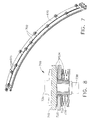
Figure 6 is a schematic side view of a heat exchanger assembly; -
Figure 7 is a schematic view of a heat exchanger assembly; -
Figure 8 is a schematic view of a mounting system for a heat exchanger assembly. - The following detailed description illustrates exemplary mounting systems and methods of assembling the same by way of example and not by way of limitation. The description should clearly enable one of ordinary skill in the art to make and use the disclosure, and the description describes several embodiments, adaptations, variations, alternatives, and uses of the disclosure, including what is presently believed to be the best mode of carrying out the disclosure. The disclosure is described herein as being applied to a preferred embodiment as applied to a gas turbine engine assembly. However, it is contemplated that this disclosure has general application in a broad range of systems and/or a variety of other commercial, industrial, and/or consumer applications.
- In general terms, a heat exchanger assembly for a gas turbine engine and a mounting system is disclosed herein. The heat exchanger assembly includes a plurality of arcuate manifolds each supporting an array of fins extending from a radial inner surface. A plurality of circumferentially extending spaced weld tabs is integrally formed on the radial outer surface. A bracket assembly is utilized to attach the heat exchanger to a structural member of a gas turbine engine assembly, e.g., a fan case, in such a manner as to maximize the surface area available for fin placement, and to not interfere with the cooling circuits within the manifold. The mounting system provides adequate stiffness for high cycle fatigue loads (i.e., vibrations) and allows relative slippage between the heat exchanger and the fan case to accommodate thermal expansion and contraction to address low cycle fatigue loads.
-
Figure 1 is a schematic illustration of an exemplary gasturbine engine assembly 500. Gasturbine engine assembly 500 has acenterline axis 502 and a radius R (shown inFigure 2 ) and includes anintake side 504, anexhaust side 506, afan assembly 508, and a coregas turbine engine 510.Fan assembly 508 includes an array offan blades 512 extending radially outward from arotor disk 514 and positioned axially forward of abypass duct 516 defined between afirst duct surface 518 and asecond duct surface 522. In an exemplary embodiment, aheat exchanger assembly 600 is coupled to afan case 520 axially aftward offan assembly 508 such thatheat exchanger assembly 600 is exposed to an airflow AF throughbypass duct 516. In other embodiments, aheat exchanger assembly 600 may be mounted at any suitable location on gasturbine engine assembly 500. -
Figure 2 is a side elevation view of an exemplaryheat exchanger assembly 600 shown mounted in operational engagement withfan case 520. In an exemplary embodiment,heat exchanger assembly 600 includes a plurality of substantially similar circumferentially extendingheat exchangers 602. Eachheat exchanger 602 has afirst end 604, asecond end 606, and a substantiallyarcuate body 608 extending betweenfirst end 604 andsecond end 606, such thatheat exchanger 602 substantially conforms to a profile of bypass duct 516 (shown inFigure 1 ).Heat exchanger assembly 600 may have any suitable number ofheat exchangers 602 having any suitable profile that enablesheat exchanger assembly 600 to function as described herein. - In an exemplary embodiment,
first end 604 may be fixedly coupled (e.g., bolted) to afan case 520 andbody 608 andsecond end 606 are slideably coupled tofan case 520 via a plurality ofmounting systems 700, as described below. Eachheat exchanger 602 may be coupled tofan case 520 via any suitable number ofmounting systems 700. In an exemplary embodiment about 20mounting systems 700 may be utilized for eachheat exchanger 602. In an exemplary embodiment,first end 604 includes an inlet port (not shown) and an outlet port (not shown) to facilitatecoupling heat exchanger 602 to at least one fluid transfer line (not shown) and directing a flow of heated fluid throughheat exchanger 602 to be cooled. - In an exemplary embodiment,
heat exchanger assembly 600 is coupled tofan case 520 such thatheat exchangers 602 are circumferentially spaced apart from one another (e.g., by at least .25 inches, for example). In one embodiment, a faring (not shown) substantially spans the space betweenadjacent heat exchangers 602 to facilitate a smoother flow of air overheat exchanger assembly 600. Alternatively,heat exchanger assembly 600 may be mounted at any suitable location on gasturbine engine assembly 500 using any suitable fasteners, such thatheat exchangers 602 have any suitable orientation relative to one another. - With particular reference to
Figures 3-8 , in an exemplary embodiment,heat exchanger 602 includes amanifold 610 and a plurality ofcooling fins 612 radially extending frommanifold 610. Manifold 610 includes a radiallyinner surface 614, a radiallyouter surface 616, an upstream wall 618, and an oppositedownstream wall 620, such thatmanifold 610 has a substantially rectangular cross-sectional profile. Manifold 610 defines at least onechannel 622 that extends lengthwise therethrough and is selectively sized to facilitate channeling a flow of heated fluid (e.g., oil) to be cooled. In an exemplary embodiment, eachchannel 622 has a substantially rectangular cross-sectional profile. In other embodiments,manifold 610 and/or eachchannel 622 may have any suitable cross-sectional profile (e.g., circular). -
Heat exchanger 602 may include anintegral manifold 610 andcooling fins 612 formed together via an aluminum extrusion process. In other embodiments, eachcooling fin 612 may be coupled to manifold 610 via a bonding process (e.g., a welding process or a brazing process) and/or formed as a non-segmented, unitary body. Alternatively,heat exchanger 602 may be fabricated via any suitable manufacturing process and/or from any suitable material. As discussed in greater detail below,manifold 610 may have a plurality of circumferential integrally formedweld tabs 615 to facilitate mounting the heat exchangers onto the fan case. - In an exemplary embodiment, each mounting
system 700 facilitatescoupling heat exchanger 602 tofan case 520 at aslot 524 that extends substantially radially through awall 560 offan case 520. Specifically,slot 524 has afirst end 526 defined on a radially innerfirst surface 544 ofwall 560, asecond end 528 defined on a radially outersecond surface 546 ofwall 560, and a length SL (seeFigure 4 ) extending fromfirst end 526 tosecond end 528, such thatslot 524 has an elongated cross-sectional profile (i.e., amajor axis 530 and aminor axis 532;Figure 5 ). In other embodiments,slot 524 may have any suitable shape and/or cross-sectional profile that enables mountingsystem 700 to function as described herein. - Exemplary embodiments enable surfaces to be protected from wear during sliding operation of the slip joint. For example anti-wear members or coatings may be utilized. For ease of illustration the anti-wear members or coatings are referenced as
anti-wear elements 534. In an exemplary embodiment,anti-wear elements 534 are suitably coupled towall 560 proximate to slot 524. Specifically, ananti-wear element 534 includes afirst portion 536 coupled tofirst surface 544 ofwall 560 circumferentially aboutslot 524, asecond portion 538 coupled tosecond surface 546 ofwall 560 circumferentially aboutslot 524, and athird portion 540 coupled to aninterior surface 542 ofslot 524. In one embodiment,second portion 538 andthird portion 540 may be integrally formed together and separately fromfirst portion 536. In other embodiments,anti-wear element 534 may have any suitable number of portions that are either formed integrally together or formed separately from one another. - In an exemplary embodiment, a plurality of mounting
systems 700 are utilized to mount theheat exchanger assemblies 600 to a structure in the gas turbine engine, for example, a fan case. The mountingsystems 700 provide adequate stiffness to address vibrational concerns, while allowing for thermal expansion of the heat exchangers both axially and circumferentially. - In an exemplary embodiment, each mounting
system 700 may include abracket 702 and a slip joint 704 to facilitate coupling theheat exchanger 602 to thefan case 520 or other engine structure.Bracket 702 includes afastener assembly 735 for receiving abolt 738 of the slip joint 704. In an exemplary embodiment,fastener assembly 735 includes a fixednut plate 736 whereby attachment of the slip joint 704 tobracket 702 is accomplished by turning thebolt 738 rather than by tightening a nut, which may be accomplished from the outer diameter offan case 520, as set forth in greater detail below. - In an exemplary embodiment,
bracket 702 includes afirst arm 706, asecond arm 708, and a base 710 that extends betweenfirst arm 706 andsecond arm 708. In an exemplary embodiment, the length ofbracket 702 is less than a width ofmanifold 610, as illustrated inFigure 3 .First arm 706 has a first length AL1, andsecond arm 708 has a second length AL2. In an exemplary embodiment, second length AL2 may be greater than first length AL1 if warranted by the particular application. In an exemplary embodiment,bracket 702 is fixedly secured at thefirst arm 706 and thesecond arm 708 to spacedweld tabs 615. In anexemplary embodiment manifold 706 includes at least threecontinuous weld tabs 615 to accommodate the length ofbrackets 702. The continuous weld tabs allow for placement ofbrackets 702 at various positions along themanifold 706. In an exemplary embodiment,brackets 702 are spaced unevenly along the length of the manifold 706 to minimize or prevent sinusoidal modes in the heat exchanger. In an exemplary embodiment, the brackets allow for varied positions of thefastener assemblies 735 along the axial length of thebrackets 702. In an exemplary embodiment, manifold 706 may accommodate two circumferential rows ofbrackets 702 which may be offset relative each other. In other exemplary embodiments,manifold 706 includes fourcontinuous weld tabs 615. Other arrangements of brackets and weld tabs are contemplated within the scope of this disclosure and the foregoing description is given by way of example only. In an exemplary embodiment, a spacer 716 (e.g., a steel spacer) may be coupled to abottom face 718 ofbase 710 via at least one fastener (e.g., a rivet 720). - In an exemplary embodiment,
slip mount 704 includes a retainer plate orwasher 722, astandoff 724, and a biasing element 726 (e.g., wave spring).Standoff 724 includes a hollow elongated member orbushing 728, which has a length CL, and aflange 730 extending outwardly fromelongated member 728. In an exemplary embodiment,elongated member 728 functions to limit the movement ofbolt 738 relative thebracket 702, and thus limits or preloads the compression of biasing element (wave spring) 726. The amount of compression of biasing element (wave spring) 726 influences the biasing force exerted by the slip joint ontofan case 520. The biasing force is sufficient to withstand vibrational forces, but less than thermal forces, herein referred to as "sliding forces." Thus, the joint will not move due to smaller vibration forces, but it will slide when the sliding force from thermal growth tendencies exceeds the preloaded biasing force. - In one embodiment,
flange 730 includes alip 760 to facilitate supportingbiasing element 726 aboutelongated member 728. In another embodiment,flange 730 is formed integrally withelongated member 728 and extends circumferentially outward fromelongated member 728.Washer 722 and biasingelement 726 are substantially annular such thatelongated member 728 is insertable through biasingelement 726 and/orwasher 722, as described below. In other embodiments,standoff 724,washer 722, and/or biasingelement 726 may include any suitable structure and may be formed integrally together or separately from one another to enable mountingsystem 700 to function as described herein. - In an exemplary embodiment, mounting
system 700 also includes alocking device 740 including acap 742 seated againstflange 730, afoot 744 either formed with or coupled towasher 722, and a link 746 (e.g., a cable) extending betweenfoot 744 andcap 742 to facilitate holdingbiasing element 726 betweenwasher 722 andflange 730. In other embodiments, lockingdevice 740 may include any suitable structure that enables lockingdevice 740 to function as described herein. - To assemble mounting
system 700,bracket 702 is positionedadjacent fan case 520 such thatspacer 716 is seated againstfirst portion 536 ofanti-wear element 534 and such thatmanifold 610 is oriented at an angle θ relative tobase 710. In this way, radiallyinner surface 614 ofmanifold 610 is substantially aligned with a contour offirst duct surface 518 such that only coolingfins 612 extend intobypass duct 516. - In an exemplary embodiment, upstream wall 618 and
downstream wall 620 ofmanifold 610 are spaced fromfirst duct surface 518 by a first gap G1 and a second gap G2, respectively, to facilitate permittingmanifold 610 to expand alongcenterline axis 502 when heated, as described below. In one embodiment, afirst seal 732 substantially covers first gap G1, and a second seal 734 substantially covers second gap G2 to facilitate blocking airflow through first gap G1 and/or second gap G2 during operation of gasturbine engine assembly 500. - With
bracket 702 positionedadjacent fan case 520,standoff 724 is inserted throughslot 524 with biasingelement 726 andwasher 722 circumscribingelongated member 728 such that biasingelement 726 is held betweenflange 730 andwasher 722 via lockingdevice 740. Lockingdevice 740 is useful to facilitate easier handling ofslip mount 704 with biasingelement 726 andwasher 722 positioned aboutelongated member 728. - When
elongated member 728 contacts spacer 716, abolt 738 is inserted through elongatedmember 728 such thatbolt 738 engages anut 736 and/orbracket 702 to facilitatefastening bracket 702 tofan case 520. A frictional engagement is thus established betweenspacer 716 andfirst portion 536 ofanti-wear element 534 and betweenwasher 722 andsecond portion 538 ofanti-wear element 534. - In an exemplary embodiment, length CL of
elongated member 728 is greater than length SL ofslot 524 such that, when a user applies torque to bolt 738, a limited load is transferred to fan case 520 (i.e., a first predetermined load is transferred tofan case 520 viaflange 730, biasingelement 726, and/orwasher 722, and a second predetermined load is transferred tobracket 702 via elongated member 728). The frictional engagement between mountingsystem 700 andfan case 520 is thus limited to a predetermined amount that is sufficient to stabilize mountingsystem 700 against high cycle fatigue, such as vibration. However, when a sliding force overcomes the frictional engagement,standoff 724 and bolt 738 are able to slide alongmajor axis 530 ofslot 524 to mitigate the effects of low cycle fatigue, such as a thermal growth and contraction ofheat exchanger 602. - In operation, a heated fluid (e.g., oil) is directed through
channels 622 ofheat exchanger 602 via the inlet and outlet ports atfirst end 604. When the heated fluid flows throughmanifold 610, heat is transferred from the heated fluid to coolingfins 612 viamanifold 610 and is dissipated from coolingfins 612 into air flowing through cooling fins 612 (i.e., air flowing through bypass duct 516) to facilitate reducing a temperature of the heated fluid flowing throughmanifold 610. - When the heated fluid flows through
manifold 610, a temperature ofmanifold 610 increases such that a material from whichmanifold 610 is fabricated (e.g., aluminum) expands. Becauseheat exchanger 602 is fixed tofan case 520 atfirst end 604, the expansion ofmanifold 610 facilitates a lengthwise extension of manifold 610 (i.e., a first circumferential displacement of second end 606). The lengthwise extension ofmanifold 610 facilitates causingbracket 702 to slide circumferentially in a first direction D' alongfirst surface 544 offan case 520 such thatstandoff 724 and bolt 738 slide a distance DD alongmajor axis 530 ofslot 524. - When the temperature of
manifold 610 is subsequently reduced, the material (e.g., aluminum) ofmanifold 610 contracts, which facilitates a lengthwise contraction of manifold 610 (i.e., a second circumferential displacement of second end 606). Specifically, the lengthwise contraction ofmanifold 610 facilitates causingbracket 702 to slide circumferentially alongfirst surface 544 offan case 520 in a second direction D" that is substantially opposite first direction D' such thatstandoff 724 and bolt 738 slide back first distance DD alongmajor axis 530. In one embodiment,slot 524,elongated member 728, and/or bolt 738 are sized to facilitate a lengthwise extension of manifold by about .3 inches (i.e., sized such that distance DD can be up to .3 inches). In other embodiments,slot 524,elongated member 728, and/or bolt 738 are sized to facilitate any suitable lengthwise extension ofmanifold 610. - The methods and systems described herein facilitate mounting a device to a structural member such as the wall of a fan case and permitting relative sliding movement therebetween. In an exemplary embodiment, the methods and systems described herein facilitate supporting a heat exchanger in high cycle fatigue (HCF) and low cycle fatigue (LCF) load conditions (i.e., providing sufficiently stable support to the heat exchanger under HCF loads, while permitting sufficient circumferential slippage of the heat exchanger under thermally induced LCF loads).
- Specifically, the methods and systems described herein facilitate limiting a user applied torque load transferred to the fan case, while facilitating ensuring that a sufficient load is transferred to the fan case to facilitate generating a frictional engagement between the slip mount and the fan case to stabilize the heat exchanger under HCF loads. The methods and systems described herein further facilitate enabling the heat exchanger to expand lengthwise such that thermally induced deflection and/or LCF stress applications to either the heat exchanger and/or the fan case are facilitated being minimized, while wear damage to the fan case during thermally induced slippage is facilitated being reduced.
- Additionally, the methods and systems described herein facilitate providing a mounting system that is sized to facilitate reliably supporting a heat exchanger in a relatively limited space, while orienting the mounting system to facilitate enabling sufficient access to the mounting system by maintenance personnel. Moreover, the methods and systems described herein facilitate increasing an efficiency of a gas turbine engine and reducing a manufacturing cost associated with fabricating a heat exchanger for a gas turbine engine, while increasing a reliability of the heat exchanger and extending a useful life of the heat exchanger.
- Exemplary embodiments of mounting systems and methods of assembling the same are described above in detail. The methods and systems are not limited to the specific embodiments described herein, but rather, components of the methods and systems may be utilized independently and separately from other components described herein. For example, the methods and systems described herein may have other industrial and/or consumer applications and are not limited to practice with only gas turbine engines. Rather, the present invention can be implemented and utilized in connection with many other industries.
- While the invention has been described in terms of various specific embodiments, those skilled in the art will recognize that the invention can be practiced with modification within the spirit and scope of the claims.
- Various aspects and embodiments of the present invention are defined by the following numbered clauses:
- 1. An assembly comprising:
- a first member comprising an arcuate body having a plurality of fins extending from a radial inner surface and a plurality of circumferentially extending spaced attachment sites defined on a radial outer surface; and
- a bracket assembly attached in supported connection with the first member by at least one of the attachment sites, wherein the bracket assembly is sized and configured for operable association with a slip joint assembly for supported attachment of the heat exchanger assembly to a structural body of a gas turbine assembly.
- 2. The assembly according to clause 1 wherein the bracket assembly includes a bracket having a base portion arranged in spaced relationship to the radial outer surface.
- 3. The assembly according to
clause 2 having an opening defined in the base portion being sized and configured for reception of an attachment member. - 4. The assembly according to
clause 3 wherein the bracket assembly includes a fastener member selectively secured to the base portion proximate the opening, wherein the fastener member extends in the space between the base portion and the radial outer surface. - 5. The assembly according to
clause 4 wherein the bracket includes first and 0second arm portions extending from the base portion to provide the bracket with a c-shaped cross section. - 6. The assembly according to
clause 5 wherein the arcuate body of the first member comprises an integral extruded metallic body. - 7. The assembly according to clause 6 wherein each attachment site includes a continuous weld tab.
- 8. The assembly according to clause 7 further comprising
a slip joint assembly operably associated with the bracket assembly wherein the slip joint assembly is configured to allow concerted sliding movement of the first member, the bracket assembly and the slip joint assembly relative to a structural body of a gas turbine assembly when a sliding force acting on the slip joint assembly exceeds a predetermined biasing force, and to prevent the concerted sliding movement when the sliding force does not exceed the predetermined sticking force. - 9. The assembly according to clause 8 wherein the slip joint assembly includes:
- a standoff including a hollow elongated member and a flange extending outwardly from the elongated member;
- a biasing element operably positioned about the elongated member; and
- a retaining member disposed about the elongated member, wherein the biasing element is positioned between the flange and the retaining member.
- 10. The assembly according to clause 8 further comprising:
- the structural body of the gas turbine engine having at least one opening therein, wherein at least a portion of the hollow elongated member extends through the opening; and
- at least one wear-resistant element operably situated between the slip joint assembly and the structural body such that at least one surface of the structural body is protected against wear from the relative movement of the slip joint assembly.
- 11. The assembly according to clause 10 further comprising:
- a bolt operably associated with the slip joint assembly and the bracket assembly such that the bolt extends through the elongated member and is selectively secured by the fastening member.
- 12. An assembly comprising:
- a first member comprising an arcuate body having a plurality of fins extending from a radial inner surface and a plurality of circumferentially extending weld tabs defined on a radial outer surface; and
- a bracket assembly including a bracket having a base portion and first and second arm portions extending from the base portion to provide the bracket with a c-shaped cross section, wherein each of the first and second arm portions are fixedly secured to an associated weld tab such that the base portion is arranged in spaced relationship to the radial outer surface, the bracket having an opening defined in the base portion being sized and configured for reception of an attachment member and wherein the bracket assembly includes a fastener member extending in the space between the base portion and the radial outer surface proximate the opening.
Claims (10)
- An assembly (600) characterized by:a first member (602) comprising an arcuate body (608) having a plurality of fins (612) extending from a radial inner surface (614) and a plurality of circumferentially extending spaced attachment sites (615) defined on a radial outer surface (616); anda bracket assembly (700) attached in supported connection with the first member by at least one of the attachment sites, wherein the bracket assembly is sized and configured for operable association with a slip joint assembly (704) for supported attachment of the heat exchanger assembly to a structural body (520) of a gas turbine assembly.
- The assembly according to claim 1 wherein the bracket assembly includes a bracket (702) having a base portion (710) arranged in spaced relationship to the radial outer surface (616).
- The assembly according to claim 2 having an opening defined in the base portion being sized and configured for reception of an attachment member.
- The assembly according to any of the claims 1, 2, and 3 wherein the bracket assembly includes a fastener member (738) selectively secured to the base portion proximate the opening, wherein the fastener member extends in the space between the base portion (710) and the radial outer surface (616).
- The assembly according to any of the claims 2, 3 and 4 wherein the bracket includes first and second arm portions (706, 708) extending from the base portion (710) to provide the bracket with a c-shaped cross section.
- The assembly according to any of the claims 1, 2, 3, 4 and 5 wherein the arcuate body of the first member (602) comprises an integral extruded metallic body.
- The assembly according to any of the claims 1, 2, 3, 4, 5 and 6 wherein each attachment site includes a continuous weld tab (615).
- The assembly according to any of the claims 1, 2, 3, 4, 5, 6 and 7 further comprising
a slip joint assembly (704) operably associated with the bracket assembly wherein the slip joint assembly is configured to allow concerted sliding movement of the first member (610), the bracket assembly (700) and the slip joint assembly (704) relative to the structural body (520) of a gas turbine assembly when a sliding force acting on the slip joint assembly exceeds a predetermined biasing force, and to prevent the concerted sliding movement when the sliding force does not exceed the predetermined sticking force. - The assembly according to claim 8 wherein the slip joint assembly includes:a standoff (724) including a hollow elongated member (728) and a flange (730) extending outwardly from the elongated member;a biasing element (726) operably positioned about the elongated member; anda retaining member (722) disposed about the elongated member, wherein the biasing element is positioned between the flange and the retaining member.
- The assembly according to claim 8 further comprising:the structural body (520) of the gas turbine engine having at least one opening (524) therein, wherein at least a portion of the hollow elongated member extends through the opening;at least one wear-resistant element (534) operably situated between the slip joint assembly (704) and the structural body (520) such that at least one surface of the structural body is protected against wear from the relative movement of the slip joint assembly; anda bolt (738) operably associated with the slip joint assembly and the bracket assembly such that the bolt extends through the elongated member and is selectively secured by the fastening member (738).
Applications Claiming Priority (2)
| Application Number | Priority Date | Filing Date | Title |
|---|---|---|---|
| US28933409P | 2009-12-22 | 2009-12-22 | |
| US12/827,877 US20110146944A1 (en) | 2009-12-22 | 2010-06-30 | Heat Exchanger Mounting Assembly |
Publications (1)
| Publication Number | Publication Date |
|---|---|
| EP2339144A2 true EP2339144A2 (en) | 2011-06-29 |
Family
ID=43617036
Family Applications (1)
| Application Number | Title | Priority Date | Filing Date |
|---|---|---|---|
| EP10195796A Withdrawn EP2339144A2 (en) | 2009-12-22 | 2010-12-17 | Heat exchanger mounting assembly in a gas turbine |
Country Status (4)
| Country | Link |
|---|---|
| US (1) | US20110146944A1 (en) |
| EP (1) | EP2339144A2 (en) |
| JP (1) | JP2011149420A (en) |
| CN (1) | CN102135036A (en) |
Cited By (10)
| Publication number | Priority date | Publication date | Assignee | Title |
|---|---|---|---|---|
| EP2871331A3 (en) * | 2013-11-06 | 2015-07-08 | United Technologies Corporation | Method for tight control of bolt holes in fan assembly |
| EP3121431A1 (en) * | 2015-07-23 | 2017-01-25 | Unison Industries LLC | Fan casing assemblies and method of mounting a cooler to a fan casing |
| EP3187724A1 (en) * | 2015-12-28 | 2017-07-05 | General Electric Company | Method and system for combination heat exchanger |
| WO2017201279A1 (en) * | 2016-05-18 | 2017-11-23 | Unison Industries, Llc | Turbine engine cooler assembly |
| EP3287621A1 (en) * | 2016-08-22 | 2018-02-28 | United Technologies Corporation | Heat exchanger for gas turbine engine with support damper mounting |
| WO2018009259A3 (en) * | 2016-05-11 | 2018-03-01 | General Electric Company | Gas turbine engine having a surface cooler with ogv oriented fin angles |
| EP3336333A1 (en) * | 2016-12-16 | 2018-06-20 | Rolls-Royce plc | Mount structure |
| EP3348800A1 (en) * | 2017-01-13 | 2018-07-18 | Unison Industries LLC | Fan casing assembly with cooler and method of moving |
| EP3366909A1 (en) * | 2017-02-24 | 2018-08-29 | Unison Industries LLC | Turbine engine with thermal seal |
| US11008943B2 (en) | 2016-08-31 | 2021-05-18 | Unison Industries, Llc | Fan casing assembly with cooler and method of moving |
Families Citing this family (21)
| Publication number | Priority date | Publication date | Assignee | Title |
|---|---|---|---|---|
| WO2012135956A1 (en) * | 2011-04-07 | 2012-10-11 | Dana Canada Corporation | Heat exchanger with resiliently mounted bracket |
| US10316754B2 (en) | 2013-03-14 | 2019-06-11 | United Technologies Corporation | Gas turbine engine heat exchanger manifold |
| US9677474B2 (en) * | 2013-11-18 | 2017-06-13 | Unison Industries, Llc | Surface cooler support mechanism |
| US9890953B2 (en) * | 2014-01-10 | 2018-02-13 | United Technologies Corporation | Attachment of ceramic matrix composite panel to liner |
| US20160215701A1 (en) * | 2015-01-22 | 2016-07-28 | General Electric Company | Inner seal for a turbomachine transition piece frame assembly |
| US10060353B2 (en) | 2015-08-14 | 2018-08-28 | United Technologies Corporation | Heat exchanger for cooled cooling air |
| WO2017048260A1 (en) * | 2015-09-17 | 2017-03-23 | Cummins Emission Solutions Inc. | Aftertreatment system mounting assembly |
| US10697371B2 (en) | 2015-12-28 | 2020-06-30 | General Electric Company | Method and system for a combined air-oil cooler and fuel-oil cooler heat exchanger |
| US20180058472A1 (en) * | 2016-08-31 | 2018-03-01 | Unison Industries, Llc | Fan casing assembly with cooler and method of moving |
| US10247296B2 (en) * | 2016-12-12 | 2019-04-02 | General Electric Company | Additively manufactured gearbox with integral heat exchanger |
| GB201700100D0 (en) * | 2017-01-05 | 2017-02-22 | Rolls Royce Plc | A Mount assembly |
| US11466700B2 (en) | 2017-02-28 | 2022-10-11 | Unison Industries, Llc | Fan casing and mount bracket for oil cooler |
| GB201712242D0 (en) * | 2017-07-31 | 2017-09-13 | Rolls Royce Plc | A mount assembly |
| US10815934B2 (en) | 2017-12-21 | 2020-10-27 | Unison Industries, Llc | Integral preloaded formed bracket for attachment of heat exchangers |
| US11143105B2 (en) * | 2018-12-19 | 2021-10-12 | Unison Industries, Llc | Mounting assembly and fan casing assembly |
| US11285348B2 (en) | 2019-08-08 | 2022-03-29 | Kidde Technologies, Inc. | Mounting assemblies for fire and overheat detection systems |
| US11448132B2 (en) | 2020-01-03 | 2022-09-20 | Raytheon Technologies Corporation | Aircraft bypass duct heat exchanger |
| US11525637B2 (en) | 2020-01-19 | 2022-12-13 | Raytheon Technologies Corporation | Aircraft heat exchanger finned plate manufacture |
| US11674758B2 (en) | 2020-01-19 | 2023-06-13 | Raytheon Technologies Corporation | Aircraft heat exchangers and plates |
| US11585273B2 (en) | 2020-01-20 | 2023-02-21 | Raytheon Technologies Corporation | Aircraft heat exchangers |
| US11585605B2 (en) | 2020-02-07 | 2023-02-21 | Raytheon Technologies Corporation | Aircraft heat exchanger panel attachment |
Family Cites Families (19)
| Publication number | Priority date | Publication date | Assignee | Title |
|---|---|---|---|---|
| GB1485032A (en) * | 1974-08-23 | 1977-09-08 | Rolls Royce | Gas turbine engine casing |
| US4072327A (en) * | 1976-10-01 | 1978-02-07 | Caterpillar Tractor Co. | Slip joint between a gas turbine engine and a heat exchanger |
| US4071194A (en) * | 1976-10-28 | 1978-01-31 | The United States Of America As Represented By The Secretary Of The Navy | Means for cooling exhaust nozzle sidewalls |
| US4187675A (en) * | 1977-10-14 | 1980-02-12 | The United States Of America As Represented By The Secretary Of The Air Force | Compact air-to-air heat exchanger for jet engine application |
| US4458866A (en) * | 1978-10-26 | 1984-07-10 | The Garrett Corporation | Heat exchanger support system providing for thermal isolation and growth |
| US5557932A (en) * | 1986-06-06 | 1996-09-24 | The United States Of America As Represented By The Secretary Of The Air Force | Low thermal stress impingement cooling apparatus |
| US5273249A (en) * | 1992-11-12 | 1993-12-28 | General Electric Company | Slide joint bracket |
| JP3525567B2 (en) * | 1995-07-17 | 2004-05-10 | 東海ゴム工業株式会社 | Cylindrical anti-vibration support |
| GB2313161B (en) * | 1996-05-14 | 2000-05-31 | Rolls Royce Plc | Gas turbine engine casing |
| US6360899B1 (en) * | 1998-12-24 | 2002-03-26 | Adams Mfg. Corp. | Cord wrap with integrally molded light holders and method for making same |
| GB9922619D0 (en) * | 1999-09-25 | 1999-11-24 | Rolls Royce Plc | A gas turbine engine blade containment assembly |
| US6557816B2 (en) * | 2000-02-07 | 2003-05-06 | Fuji Photo Film Co., Ltd. | Motor mounting structure and drive shaft mounting structure |
| US6422520B1 (en) * | 2000-06-27 | 2002-07-23 | James F. Hand | Universal mounting bracket |
| EP1649145B1 (en) * | 2003-07-29 | 2008-05-28 | Pratt & Whitney Canada Corp. | Turbofan casing, turbofan engine and corresponding method |
| US7370467B2 (en) * | 2003-07-29 | 2008-05-13 | Pratt & Whitney Canada Corp. | Turbofan case and method of making |
| US6951324B2 (en) * | 2003-09-17 | 2005-10-04 | John Chris Karamanos | Universal bracket for transporting an assembled conduit |
| US20050120719A1 (en) * | 2003-12-08 | 2005-06-09 | Olsen Andrew J. | Internally insulated turbine assembly |
| US8387362B2 (en) * | 2006-10-19 | 2013-03-05 | Michael Ralph Storage | Method and apparatus for operating gas turbine engine heat exchangers |
| JP2008227181A (en) * | 2007-03-13 | 2008-09-25 | Nippon Densan Corp | Method of manufacturing fin unit, fin unit, and cooling device |
-
2010
- 2010-06-30 US US12/827,877 patent/US20110146944A1/en not_active Abandoned
- 2010-12-17 EP EP10195796A patent/EP2339144A2/en not_active Withdrawn
- 2010-12-21 CN CN2010106208749A patent/CN102135036A/en active Pending
- 2010-12-21 JP JP2010283944A patent/JP2011149420A/en not_active Withdrawn
Non-Patent Citations (1)
| Title |
|---|
| None |
Cited By (21)
| Publication number | Priority date | Publication date | Assignee | Title |
|---|---|---|---|---|
| US10502235B2 (en) | 2013-11-06 | 2019-12-10 | United Technologies Corporation | Method for tight control of bolt holes in fan assembly |
| EP3192981A1 (en) * | 2013-11-06 | 2017-07-19 | United Technologies Corporation | Fan case assembly |
| EP2871331A3 (en) * | 2013-11-06 | 2015-07-08 | United Technologies Corporation | Method for tight control of bolt holes in fan assembly |
| US11236769B2 (en) | 2013-11-06 | 2022-02-01 | Raytheon Technologies Corporation | Method for tight control of bolt holes in fan assembly |
| EP3121431A1 (en) * | 2015-07-23 | 2017-01-25 | Unison Industries LLC | Fan casing assemblies and method of mounting a cooler to a fan casing |
| EP3591209A1 (en) * | 2015-07-23 | 2020-01-08 | Unison Industries LLC | Fan casing assembly |
| US10393147B2 (en) | 2015-07-23 | 2019-08-27 | Unison Industries, Llc | Fan casing assemblies and method of mounting a cooler to a fan casing |
| EP3187724A1 (en) * | 2015-12-28 | 2017-07-05 | General Electric Company | Method and system for combination heat exchanger |
| CN107035527A (en) * | 2015-12-28 | 2017-08-11 | 通用电气公司 | Method and system for unitized exchanger |
| US11125160B2 (en) | 2015-12-28 | 2021-09-21 | General Electric Company | Method and system for combination heat exchanger |
| WO2018009259A3 (en) * | 2016-05-11 | 2018-03-01 | General Electric Company | Gas turbine engine having a surface cooler with ogv oriented fin angles |
| US10823067B2 (en) | 2016-05-11 | 2020-11-03 | General Electric Company | System for a surface cooler with OGV oriented fin angles |
| WO2017201279A1 (en) * | 2016-05-18 | 2017-11-23 | Unison Industries, Llc | Turbine engine cooler assembly |
| US10428834B2 (en) | 2016-05-18 | 2019-10-01 | Unison Industries, Llc | Turbine engine cooler assembly |
| EP3287621A1 (en) * | 2016-08-22 | 2018-02-28 | United Technologies Corporation | Heat exchanger for gas turbine engine with support damper mounting |
| US11008943B2 (en) | 2016-08-31 | 2021-05-18 | Unison Industries, Llc | Fan casing assembly with cooler and method of moving |
| US10731567B2 (en) | 2016-12-16 | 2020-08-04 | Rolls-Royce Plc | Mount structure for an aircraft ancillary engine unit |
| EP3336333A1 (en) * | 2016-12-16 | 2018-06-20 | Rolls-Royce plc | Mount structure |
| EP3348800A1 (en) * | 2017-01-13 | 2018-07-18 | Unison Industries LLC | Fan casing assembly with cooler and method of moving |
| US10514005B2 (en) | 2017-02-24 | 2019-12-24 | Unison Industries, Llc | Turbine engine thermal seal |
| EP3366909A1 (en) * | 2017-02-24 | 2018-08-29 | Unison Industries LLC | Turbine engine with thermal seal |
Also Published As
| Publication number | Publication date |
|---|---|
| CN102135036A (en) | 2011-07-27 |
| US20110146944A1 (en) | 2011-06-23 |
| JP2011149420A (en) | 2011-08-04 |
Similar Documents
| Publication | Publication Date | Title |
|---|---|---|
| EP2339159B1 (en) | Method of mounting a heat exchanger in a gas turbine engine assembly | |
| EP2339144A2 (en) | Heat exchanger mounting assembly in a gas turbine | |
| EP3129607B1 (en) | Turbine center frame fairing assembly | |
| EP2126289B1 (en) | Transition support system for combustion transition ducts for turbine engines | |
| CA2606278C (en) | Heat exchanger system having manifolds structurally integrated with a duct | |
| US8794300B2 (en) | Exhaust gas cooler for a motor vehicle | |
| EP3591209B1 (en) | Fan casing assembly | |
| JP6949411B2 (en) | Mounting bracket for fan casing and oil cooler | |
| CN109154254B (en) | Turbine engine cooler assembly | |
| US11143105B2 (en) | Mounting assembly and fan casing assembly | |
| JP6622826B2 (en) | Turbine engine heat seal | |
| US11766747B2 (en) | Surface cooler assembly | |
| US11591930B2 (en) | Annular assembly for a turbomachine | |
| CN109944703B (en) | Integrated preload forming bracket for heat exchanger accessories | |
| GB2482170A (en) | A duct |
Legal Events
| Date | Code | Title | Description |
|---|---|---|---|
| PUAI | Public reference made under article 153(3) epc to a published international application that has entered the european phase |
Free format text: ORIGINAL CODE: 0009012 |
|
| AK | Designated contracting states |
Kind code of ref document: A2 Designated state(s): AL AT BE BG CH CY CZ DE DK EE ES FI FR GB GR HR HU IE IS IT LI LT LU LV MC MK MT NL NO PL PT RO RS SE SI SK SM TR |
|
| AX | Request for extension of the european patent |
Extension state: BA ME |
|
| STAA | Information on the status of an ep patent application or granted ep patent |
Free format text: STATUS: THE APPLICATION IS DEEMED TO BE WITHDRAWN |
|
| 18D | Application deemed to be withdrawn |
Effective date: 20150701 |