EP2339111A2 - Downhole apparatus and method - Google Patents
Downhole apparatus and method Download PDFInfo
- Publication number
- EP2339111A2 EP2339111A2 EP11158362A EP11158362A EP2339111A2 EP 2339111 A2 EP2339111 A2 EP 2339111A2 EP 11158362 A EP11158362 A EP 11158362A EP 11158362 A EP11158362 A EP 11158362A EP 2339111 A2 EP2339111 A2 EP 2339111A2
- Authority
- EP
- European Patent Office
- Prior art keywords
- main body
- screen
- swellable mantle
- fluid
- exterior
- Prior art date
- Legal status (The legal status is an assumption and is not a legal conclusion. Google has not performed a legal analysis and makes no representation as to the accuracy of the status listed.)
- Granted
Links
- 238000000034 method Methods 0.000 title claims description 38
- 239000012530 fluid Substances 0.000 claims abstract description 111
- 239000007787 solid Substances 0.000 claims abstract description 27
- 238000004519 manufacturing process Methods 0.000 claims abstract description 14
- 230000015572 biosynthetic process Effects 0.000 claims description 32
- 238000001914 filtration Methods 0.000 claims description 11
- 239000004215 Carbon black (E152) Substances 0.000 claims description 8
- 229930195733 hydrocarbon Natural products 0.000 claims description 8
- 150000002430 hydrocarbons Chemical class 0.000 claims description 8
- 238000012216 screening Methods 0.000 claims description 6
- 230000001419 dependent effect Effects 0.000 claims description 3
- 239000000463 material Substances 0.000 description 29
- 239000011347 resin Substances 0.000 description 6
- 229920005989 resin Polymers 0.000 description 6
- 230000000452 restraining effect Effects 0.000 description 6
- 230000003628 erosive effect Effects 0.000 description 5
- 239000002184 metal Substances 0.000 description 5
- 229910052751 metal Inorganic materials 0.000 description 5
- 239000002245 particle Substances 0.000 description 5
- XLYOFNOQVPJJNP-UHFFFAOYSA-N water Substances O XLYOFNOQVPJJNP-UHFFFAOYSA-N 0.000 description 5
- 229920002943 EPDM rubber Polymers 0.000 description 4
- 239000007864 aqueous solution Substances 0.000 description 4
- 229920001577 copolymer Polymers 0.000 description 4
- 230000002745 absorbent Effects 0.000 description 3
- 239000002250 absorbent Substances 0.000 description 3
- 239000002657 fibrous material Substances 0.000 description 3
- 229920000578 graft copolymer Polymers 0.000 description 3
- 238000007127 saponification reaction Methods 0.000 description 3
- NIXOWILDQLNWCW-UHFFFAOYSA-N Acrylic acid Chemical class OC(=O)C=C NIXOWILDQLNWCW-UHFFFAOYSA-N 0.000 description 2
- 229920000181 Ethylene propylene rubber Polymers 0.000 description 2
- 239000002174 Styrene-butadiene Substances 0.000 description 2
- MTAZNLWOLGHBHU-UHFFFAOYSA-N butadiene-styrene rubber Chemical compound C=CC=C.C=CC1=CC=CC=C1 MTAZNLWOLGHBHU-UHFFFAOYSA-N 0.000 description 2
- YACLQRRMGMJLJV-UHFFFAOYSA-N chloroprene Chemical compound ClC(=C)C=C YACLQRRMGMJLJV-UHFFFAOYSA-N 0.000 description 2
- 230000007812 deficiency Effects 0.000 description 2
- 229920001971 elastomer Polymers 0.000 description 2
- 239000000806 elastomer Substances 0.000 description 2
- 229920001477 hydrophilic polymer Polymers 0.000 description 2
- 239000007788 liquid Substances 0.000 description 2
- 239000007769 metal material Substances 0.000 description 2
- 239000000203 mixture Substances 0.000 description 2
- 230000036961 partial effect Effects 0.000 description 2
- 229920001084 poly(chloroprene) Polymers 0.000 description 2
- 229920000642 polymer Polymers 0.000 description 2
- 230000001681 protective effect Effects 0.000 description 2
- 239000011435 rock Substances 0.000 description 2
- 239000011115 styrene butadiene Substances 0.000 description 2
- 229920003048 styrene butadiene rubber Polymers 0.000 description 2
- 229920000247 superabsorbent polymer Polymers 0.000 description 2
- 239000004583 superabsorbent polymers (SAPs) Substances 0.000 description 2
- 230000008961 swelling Effects 0.000 description 2
- UONOETXJSWQNOL-UHFFFAOYSA-N tungsten carbide Chemical compound [W+]#[C-] UONOETXJSWQNOL-UHFFFAOYSA-N 0.000 description 2
- 229920002785 Croscarmellose sodium Polymers 0.000 description 1
- IMROMDMJAWUWLK-UHFFFAOYSA-N Ethenol Chemical compound OC=C IMROMDMJAWUWLK-UHFFFAOYSA-N 0.000 description 1
- 239000004372 Polyvinyl alcohol Substances 0.000 description 1
- 229920002125 Sokalan® Polymers 0.000 description 1
- NINIDFKCEFEMDL-UHFFFAOYSA-N Sulfur Chemical compound [S] NINIDFKCEFEMDL-UHFFFAOYSA-N 0.000 description 1
- 239000005864 Sulphur Substances 0.000 description 1
- 230000000903 blocking effect Effects 0.000 description 1
- 238000009792 diffusion process Methods 0.000 description 1
- 230000000694 effects Effects 0.000 description 1
- -1 ethylene-propylene diene Chemical class 0.000 description 1
- 238000002347 injection Methods 0.000 description 1
- 239000007924 injection Substances 0.000 description 1
- 230000000670 limiting effect Effects 0.000 description 1
- FPYJFEHAWHCUMM-UHFFFAOYSA-N maleic anhydride Chemical compound O=C1OC(=O)C=C1 FPYJFEHAWHCUMM-UHFFFAOYSA-N 0.000 description 1
- 125000005395 methacrylic acid group Chemical class 0.000 description 1
- 238000012856 packing Methods 0.000 description 1
- 230000035515 penetration Effects 0.000 description 1
- 150000002978 peroxides Chemical class 0.000 description 1
- 239000004584 polyacrylic acid Substances 0.000 description 1
- 229920002451 polyvinyl alcohol Polymers 0.000 description 1
- 150000003839 salts Chemical class 0.000 description 1
- 239000004576 sand Substances 0.000 description 1
Images


Classifications
-
- E—FIXED CONSTRUCTIONS
- E21—EARTH DRILLING; MINING
- E21B—EARTH DRILLING, e.g. DEEP DRILLING; OBTAINING OIL, GAS, WATER, SOLUBLE OR MELTABLE MATERIALS OR A SLURRY OF MINERALS FROM WELLS
- E21B43/00—Methods or apparatus for obtaining oil, gas, water, soluble or meltable materials or a slurry of minerals from wells
- E21B43/02—Subsoil filtering
- E21B43/08—Screens or liners
- E21B43/084—Screens comprising woven materials, e.g. mesh or cloth
-
- E—FIXED CONSTRUCTIONS
- E21—EARTH DRILLING; MINING
- E21B—EARTH DRILLING, e.g. DEEP DRILLING; OBTAINING OIL, GAS, WATER, SOLUBLE OR MELTABLE MATERIALS OR A SLURRY OF MINERALS FROM WELLS
- E21B43/00—Methods or apparatus for obtaining oil, gas, water, soluble or meltable materials or a slurry of minerals from wells
- E21B43/02—Subsoil filtering
- E21B43/10—Setting of casings, screens, liners or the like in wells
- E21B43/103—Setting of casings, screens, liners or the like in wells of expandable casings, screens, liners, or the like
Definitions
- the present invention relates to a downhole apparatus and method for use in the completion of hydrocarbon wells, and in one aspect to a downhole screen including a swellable material and a method of use.
- Expandable tubulars There are a number of drawbacks to using expanding tubulars. It can be difficult to control the force used to expand the tubular, and there may be resulting problems with the application of an undue, damaging force onto the formation. Expandable tubulars also have a limited expansion range, which means that maximum expansion can still result in an unsupported formation in a wash out zone.
- US 2005/0173130 describes an arrangement in which a swellable layer is located over an expanding screen to allow the apparatus to conform to the borehole shape. Holes in the swellable layer allow the passage of formation fluids. However, it is desirable in many applications to avoid the use of expanding tubulars. Additionally, by providing the screen around the expandable pipe at a location displaced from the borehole wall, there is an annular space into which solids may be produced, and along which solids may flow. This increases the risk of blocking the screen and creating so-called hotspots which are prone to erosion.
- WO 2006/003112 attempts to overcome these deficiencies by providing a screen which is expanded into contact with the borehole wall by swellable rings.
- This approach relies on overlaid screen sheets which are forced outward by the swelling of the rings. This has the undesirable effect of restraining expansion of the swellable material, which may only be capable of exerting a pressure of 50 to 100 PSI (345 to 690 KPa).
- the gaps between overlaid screen sheets provide route for solid particles to enter the production tubing.
- a downhole apparatus comprising a main body having a bore arranged to be coupled with a well tubing; and a swellable mantle disposed on the main body, which swellable mantle expands upon contact with at least one predetermined fluid; wherein the main body comprises at least one opening for fluid flow between an exterior of the main body and the bore, and the swellable mantle is provided with an insert to permit the passage of fluid between the exterior of the apparatus and the at least one opening through the swellable mantle.
- the apparatus may permit fluid flow from its exterior into the bore, through the openings in the main body, and onward to the well tubing.
- the apparatus may therefore communicate with production tubing, and may be adapted to permit flow of production fluid from a producing zone into the production tubing.
- the swellable mantle may be disposed around an elongate portion of the main body, and may form a substantially cylindrical member around the main body.
- the elongate portion may comprise at least one opening therein, and the swellable mantle may be adapted to allow the passage of fluid between the exterior of the apparatus and the at least one opening in the elongate portion.
- the apparatus may therefore be arranged to permit fluid flow across an area or surface over which the swellable mantle is disposed.
- the main body may be a tubular, and may form a base pipe of the apparatus.
- the main body may comprise a liner tubular.
- the main body comprises a plurality of openings.
- the openings may be slots or perforations.
- the main body may therefore be a slotted or pre-perforated tubular.
- the main body is formed to a fixed diameter, and is not adapted for expansion in use.
- the swellable mantle may be provided with at least one formation to promote fluid flow between the exterior of the apparatus and the at least one opening.
- the swellable mantle is provided with at least one aperture therein.
- the aperture may be a hole, groove or slot in the swellable mantle.
- the aperture may be a radial opening in the swellable mantle.
- the aperture may comprise a groove extending circumferentially of the swellable mantle, and may comprise an annular groove in the swellable mantle.
- the aperture may comprise a groove extending longitudinally of the swellable mantle.
- the aperture may comprise a groove defining a groove axis, which may be oriented longitudinally, circumferentially, or helically of the swellable mantle.
- the aperture may comprise a hole extending radially of the swellable mantle.
- the aperture may provide a fluid flow path from the exterior of the apparatus to main body.
- the apparatus may comprise a flow path from the exterior of the apparatus to the bore, via the aperture and the at least one opening in the main body.
- the flow path may be from a producing formation to the bore, via the aperture and the at least one opening in the main body.
- the insert may be provided in the aperture.
- the insert preferably permits fluid flow through the aperture.
- the insert may be adapted to maintain a flow path in the aperture.
- the insert may comprise a fluid permeable material.
- the insert may function as a filter for filtering solid particles from the fluid flowing through the aperture.
- the insert may be disposed over one or more openings of the main body.
- the insert may extend longitudinally and/ or radially of the main body.
- the insert may substantially fill a volume defined by the aperture.
- the insert may function to support or abut a portion of the swellable mantle, and may define a bearing surface for a portion of the swellable mantle.
- the insert may therefore limit or prevent the expansion of the swellable mantle in at least one direction, and may be arranged to prevent the expansion of the swellable mantle into the flow path defined by the aperture.
- the insert may be formed from a permeable rope, a braided line or a fibrous material, which may be wound into the aperture.
- the insert may comprise a sintered metal component.
- the insert may comprise an impermeable metal component having fluid apertures formed therein.
- the insert may comprise an abrasion-or erosion-resistant material such as tungsten carbide or similar.
- the insert may define a conduit in the swellable mantle.
- the insert may define a radially extending conduit through an aperture in the swellable mantle.
- the conduit may be a bounded conduit, which may be adapted to maintain a flow path in the aperture.
- the conduit may be defined by a tube.
- the conduit may extend from the exterior of the swellable mantle to main body.
- the conduit may have a first end arranged for fluid flow to and/ or from an exterior of the apparatus and a second end arranged for fluid flow to and/or from the main body.
- the second end may be located at or adjacent to the main body.
- the second end may be coupled to the apparatus at an opening on the main body.
- the second end may fully or partially extend into main body.
- the second end may be bonded to the main body.
- the conduit may be of variable length.
- the conduit may be telescopic, and may comprise a first member at the first end, movably coupled to a second member at the second end.
- the first and second members may therefore move relative to one another to create a channel of variable length. Such relative movement result from expansion of the swellable mantle.
- the second member may be bonded to the swellable mantle.
- the first member may be adapted to move relative to the second member on expansion of the swellable mantle.
- a seal may be provided between the first and second members.
- one or more flow-directing members or channels disposed on an outer surface of the apparatus.
- the flow-directing member may be adapted to couple multiple apertures, and or direct flow to multiple apertures.
- the flow-directing member may be provided with holes corresponding to apertures in the swellable mantle.
- the flow-directing member may provide a fluid path from the exterior of the apparatus to one or more apertures.
- the flow-directing member may be coupled to an insert to an aperture.
- the flow-directing member is coupled to multiple inserts, and may be integral therewith. More preferably, the flow-directing member is coupled to multiple conduits, or first members thereof. The flow directing member may partially or fully define the inserts to the apertures.
- the flow-directing member and the inserts can be considered in one embodiment to function as a gutter and a series of drainpipes respectively.
- the apparatus comprises a screen for filtering solids between the exterior of the apparatus and the bore.
- the screen is arranged to filter solids from fluid flowing from the exterior of the apparatus to the bore.
- the screen functions to filter solids produced from the formation, such as sands or shale or the like, from the fluid.
- the screen may comprise a plurality of layers.
- the screen may comprise at least one mesh layer, but preferably comprises a plurality of mesh layers.
- the screen may comprise a filter mesh layer having a filter grade of 50 microns to 350 microns.
- the screen may further comprise one or both of an outer protective shroud or a drainage support mesh layer.
- the screen comprises a first drainage support mesh layer on one side of a filter mesh layer, and a second drainage support mesh layer on an opposing side of a filter mesh layer.
- the screen is preferably disposed over the openings. More preferably, the screen is disposed over the apertures.
- the screen may be disposed in the flow directing member.
- the apparatus may comprise multiple screens at discrete locations.
- the apparatus may comprise at least two screens having different filter grades.
- the swellable mantle is preferably disposed around the main body and may be arranged to expand upon contact with at least one predetermined fluid and thereby move the screen outwardly of the main body.
- the screen is preferably arranged such that any restraining force imparted by the screen onto the swellable mantle which acts against its expansion can be overcome by the swellable mantle. More preferably, substantially no restraining force is imparted on the swellable mantle by the screen.
- the apparatus may be arranged such that the surface area of the screen is maintained in use, between an unexpanded condition and an expanded condition.
- the screen may have a screen surface area; and the swellable mantle may be disposed around the main body between the main body and the screen.
- the swellable mantle is arranged to expand upon contact with at least one predetermined fluid and thereby move the outwardly of the main body while maintaining the screen surface area.
- the swellable mantle may comprise a first region located between the main body and the screen which allows the passage of fluid between the exterior of the apparatus and the main body.
- the swellable mantle may include a second region, which may be circumferentially adjacent the first region, which substantially prevents passage of fluid between the exterior of the apparatus and the main body.
- the second region is adapted to be expanded into contact with the borehole wall.
- the screen may be discontinuous around the circumference of the main body.
- the screen may consist of multiple portions of screening material, which may be discrete in an expanded condition of the apparatus. The multiple portions may additionally be discrete in an unexpanded condition of the apparatus.
- the swellable member is disposed around the main body between the main body and the screen such that on expansion the screen is moved outwardly of the main body.
- the screen may comprise at least two discrete screens or screen sections circumferentially spaced on the apparatus.
- the swellable mantle is disposed between the main body and a borehole wall in use.
- the apparatus may be adapted to provide stand off of the main body from the bore in the apparatus is located. More preferably the swellable mantle is further adapted to provide support to a wall of the bore in which it is located.
- the apparatus may be used to support a loose or unstable borehole formation, such as a sandstone or shale formation.
- the apparatus may be adapted for compliant expansion of the swellable mantle to the formation, such that the swellable mantle contacts the formation without unduly stressing the formation. This has the advantage of reducing rock fatigue and reducing the tendency of solids to flow out of the formation with the fluid.
- swellable mantle is used herein it should not be taken to imply a single piece of swellable material unless otherwise specified. Certain embodiments of the invention comprise multiple, separate pieces of swellable material which combine to provide the so-called swellable mantle. Other embodiments comprise a unitary swellable mantle.
- the swellable material may comprise an ethylene-propylene co-polymer cross-linked with at least one of a peroxide and sulphur. More specifically the swellable member may comprise ethylene propylene diene monomer rubber (EPDM).
- EPDM ethylene propylene diene monomer rubber
- the swellable member may contain at least one or multiple water absorbing resins or more precisely any lightly cross-linked hydrophilic polymer embedded within the main swellable member elastomer which may comprise at least one of chloroprene, styrene butadiene or ethylene-propylene rubbers.
- water-absorbing resins are termed “superabsorbent polymers” or "SAPs" and when embedded within the swellable member it may expand when in contact with an aqueous solution.
- water absorbent resin examples include cross-linked polyacrylic acid salts, cross-linked copolymers of vinyl alcohol and acrylic acid salt, cross-linked products of polyvinyl alcohol grafted with maleic anhydride, crosslinked copolymers of acrylic acid salt and meth-acrylic acid salt, cross-linked saponification products of methyl acrylate-vinyl acetate copolymer, cross-linked products of starch-acrylic acid salt graft copolymer, crosslinked saponification products of starch-acrylonitrile graft copolymer, crosslinked saponification products of starch-ethyl acrylate graft copolymer, crosslinked carboxymethyl cellulose and the like.
- the swellable member may comprise an ethylene-propylene-diene polymer with embedded water absorbent resin such that expansion of the swellable member may result from contacting either an aqueous solution or polar liquid such as oil or a mixture of both.
- a well completion or hydrocarbon production method comprising the steps of:
- the method may comprise the step of allowing fluid to flow through the insert.
- the method may comprise the step of receiving fluid from the formation and into a well tubing to which the apparatus is coupled.
- the method may include the additional step of screening solids from the fluid received from the formation.
- the method may include the additional step of moving a screen outwardly of the main body during expansion of the swellable mantle.
- the method may include the step of expanding the swellable mantle without changing the surface area of the screen.
- the method may include the step of expanding the swellable mantle such that the screen consists of a plurality of discrete screen sections after expansion.
- downhole apparatus comprising a main body having a bore communicating with a well tubing, and at least one opening for fluid flow between an exterior of the main body and the bore; a screen for filtering solids between the exterior of the apparatus and the bore; and a swellable mantle disposed around the main body and arranged to expand upon contact with at least one predetermined fluid and thereby move the screen outwardly of the main body, wherein the swellable mantle comprises a first region located between the main body and the screen which allows the passage of fluid between the exterior of the apparatus and the main body; and a second region, circumferentially adjacent the first region, which substantially prevents passage of fluid between the exterior of the apparatus and the main body.
- the invention in this aspect provides a swellable mantle with a surface which is designed to permit or prevent fluid flow through circumferentially separated areas. This facilitates the use of a screen which is not continuous around the circumference of swellable mantle. The discontinuous nature of the screen permits the screen to be moved outwardly of the main body more readily than if a continuous screen were used.
- the second region is adapted to be expanded into contact with the borehole wall.
- the screen is preferably arranged such that any restraining force imparted by the screen onto the swellable mantle which acts against its expansion can be overcome by the swellable mantle. More preferably, substantially no restraining force is imparted on the swellable mantle by the screen.
- the apparatus may be arranged such that the surface area of the screen is maintained in use, between an unexpanded condition and an expanded condition.
- the screen may have a screen surface area; and the swellable mantle may be disposed around the main body between the main body and the screen.
- the swellable mantle is arranged to expand upon contact with at least one predetermined fluid and thereby move the outwardly of the main body while maintaining the screen surface area.
- the screen may be discontinuous around the circumference of the main body.
- the screen may consist of multiple portions of screening material, which may be discrete in an expanded condition of the apparatus. The multiple portions may additionally be discrete in an unexpanded condition of the apparatus.
- the swellable member is disposed around the main body between the main body and the screen such that on expansion the screen is moved outwardly of the main body.
- the screen may comprise at least two discrete screen sections circumferentially spaced on the apparatus.
- a well completion or hydrocarbon production method comprising the steps of:
- the method may comprise the step of receiving fluid from the formation and into a well tubing to which the apparatus is coupled.
- the method may include the additional step of screening solids from the fluid received from the formation.
- the method may include the step of expanding the swellable mantle without changing the surface area of the screen.
- the method may include the step of expanding the swellable mantle such that the screen consists of a plurality of discrete screen sections after expansion.
- a downhole apparatus comprising a main body having a bore communicating with a well tubing, and at least one opening for fluid flow between an exterior of the main body and the bore; a screen for filtering solids between the exterior of the apparatus and the bore having a screen surface area; and a swellable member disposed around the main body between the main body and the screen, wherein the swellable member is arranged to expand upon contact with at least one predetermined fluid and thereby move the screen outwardly of the main body while maintaining the screen surface area.
- a downhole apparatus comprising a main body having a bore communicating with a well tubing, and at least one opening for fluid flow between an exterior of the main body and the bore; a screen for filtering solids between the exterior of the apparatus and the bore; and a swellable member disposed around the main body between the main body and the screen, wherein the swellable member is arranged to expand upon contact with at least one predetermined fluid and thereby move the screen outwardly of the main body, wherein the screen comprises at least two discrete screen sections circumferentially spaced on the apparatus.
- FIG. 10 there is shown a downhole apparatus, generally depicted at 10, in accordance with an embodiment of the invention.
- the apparatus 10 comprises a main body 12 formed from tubular base pipe.
- the body 12 is adapted to be coupled to well tubing (not shown) such that the bore 14 of the apparatus communicates with the bore of the well tubing.
- a section 16 of the main body 12 extending over a length of the apparatus is provided with openings 18 or perforations distributed longitudinally and circumferentially on the section 16.
- the openings are through-openings from an exterior of the main body 12 to the bore 14.
- the openings 18 are regularly distributed, although in alternative embodiments other arrangements of openings may be provided.
- a swellable mantle 20 Disposed over the main body 12 is a swellable mantle 20.
- Figure 2 shows the mantle removed from the apparatus 10.
- the swellable mantle 20 is a substantially tubular member shaped to fit over the section 16 of the apparatus.
- the swellable mantle is sized to be bonded or slipped onto the main body, and is located on the section 16 by end rings 22.
- the end rings 22 are secured to the main body to prevent axial and radial movement and to abut the respective ends of the swellable mantle 20.
- the swellable mantle 20 is provided with apertures 24 and inserts 26 to the apertures.
- the inserts 26 are located in longitudinal recessed grooves 28 on the outer surface of the swellable mantle 20. The inserts 26 will be described in more detail below.
- the swellable mantle 20 is formed from a material which is selected to expand on contact with a predetermined fluid.
- a material which is selected to expand on contact with a predetermined fluid.
- Such swellable materials are known in the art.
- the swellable mantle is required to swell in oil, and the material comprises ethylene propylene diene monomer rubber (EPDM).
- EPDM ethylene propylene diene monomer rubber
- the material comprises any lightly crosslinked hydrophilic polymer embedded within the main swellable member elastomer, such as at least one of chloroprene, styrene butadiene or ethylene-propylene rubbers.
- Such water-absorbing resins are termed “superabsorbent polymers” or “SAPs” and when embedded within the swellable member may expand when in contact with an aqueous solution.
- the swellable member comprises an ethylene-propylene diene polymer with embedded water absorbent resin such that expansion of the swellable member results from contacting either an aqueous solution or polar liquid such as oil or a mixture of both.
- the apertures 24 function to allow fluid to flow from the exterior of the swellable mantle 20 to its interior. When the swellable mantle is positioned on the main body 12, the apertures 24 allow fluid flow from the exterior of the apparatus to the main body 12 and through the openings 18 in the main body to the bore 14.
- the spacing of the apertures 24 corresponds to the spacing of the openings 18, such that the apertures 24 and openings 18 may be aligned to provide minimal resistance to fluid flow from the exterior of the apparatus to the bore 14.
- the swellable mantle 20 functions to expand on contact with a well bore fluid such that the outer surface of the apparatus comes into contact with the borehole wall.
- the dimensions and properties of the swellable mantle are selected for compliant expansion of the swellable mantle into contact with the borehole wall, such that an appropriately low force is imparted to the borehole to create a seal, but to prevent damage to the rock formation or sandface.
- the dimensions and material of the swellable mantle are also selected to expand into a washout zone in the borehole to similarly create a seal with a suitably low force on the formation. In this way, the formation is supported from collapse towards the main body 12, but without damaging the formation in a way that would increase the inflow of solids.
- the insert includes a screen support 30 and screen material 32.
- the insert 26 therefore defines screen sections 33 of the apparatus along circumferentially spaced longitudinal regions of the swellable mantle 20. Disposed between the screen sections are longitudinal regions of the swellable mantle 20 which substantially prevent fluid flow to the interior of the mantle 20.
- the swellable material may permit fluid penetration by diffusion through the swellable material, but does not permit fluid flow such as that required for the inflow of production fluids into the bore 14 or the injection of fluids from the bore 14 into the formation.
- FIGS 4, 5A and 5B show the insert 26 in more detail, with the screen material 32 removed.
- the insert 26 includes a plurality of conduits 34 which extend through the swellable mantle to the main body. Multiple conduits are connected by a channel 35 defined by the screen support 30.
- the conduits 34 each comprise a first member 36 received in a second member 38.
- the first and second members 36, 38 are movable relative to one another to accommodate expansion of the swellable mantle 20.
- the conduits function to maintain the flow path of the aperture after expansion.
- the conduits, or a subset of conduits are provided with flow control members such as valves or check valves to restrict fluid flow therethrough.
- the second member 38 When assembled, the second member 38 is an interference fit with the aperture 24 of the swellable mantle into which it locates.
- the undersurface 42 of the screen support 30 is bonded to the surface of the swellable mantle 20 along the longitudinal groove 28.
- the second member 38 may be fixed to the main body 12 and/or may be received in the opening 18 in the main body.
- the screen material 32 is shown as comprising a plurality of overlaid layers. Adjacent the screen support 30 is provided a drainage support mesh 44, onto which is overlaid a filter mesh 46.
- the filter mesh is selected to have an appropriate mesh grade for filtering solids which may be produced from the formation. Typically, the filter mesh will have a mesh grade of around 100 to 300 microns.
- Over the filter mesh 46 is a further drainage support mesh 48, and finally an outer protective shroud 50, having relatively large apertures, is provided on the exterior of the screen material.
- the present invention encapsulates embodiments in which different screen sections are provided with different filter grades.
- the invention also facilitates customisation of the apparatus by selecting appropriate filter grades during assembly of the apparatus.
- Figure 7 shows the apparatus 10 in use in a borehole, in a swelled condition.
- the apparatus 10 has been run to a location in a sand-producing formation 51, and exposure to wellbore fluids has caused the swellable mantle 20 to expand into contact with the borehole wall 52.
- the conduits 34 defined by the inserts 26 telescopically extend such that a bounded conduit is formed between the exterior of the apparatus and the openings 18 in the main body 12.
- the inserts prevent the swellable mantle 20 from expanding to close the apertures 24.
- the screen sections 33 are placed adjacent to the sandface by expansion of the swellable mantle under the insert, and adjacent regions 54 of the swellable mantle form a compliant seal on the borehole wall 52. Fluid flow from the formation is permitted in the areas at which the screen sections 32 are provided, and is directed through the apertures 24, via the conduits 34, and into the bore 14. Flow is not permitted through the regions 54.
- This embodiment of the invention provides compliant expansion of a swellable member to a borehole wall, providing structural support to the borehole without damaging the sandface.
- the screen sections 33 are carried or moved in a radial direction to be placed adjacent to the sandface. This minimises the annular space in which solids produced from the formation can flow. The flow of fluid is only permitted in the regions at which the screen material is provided, with adjacent sections supported and sealed by the swellable mantle.
- the embodiment of the invention is also conducive to customisation and configuration of the filter grades used, which may differ between screen sections.
- a downhole apparatus generally depicted at 100 consisting of the main body 112 formed from a tubular base pipe and adapted to be coupled to well tubing in the same manner as apparatus 10.
- the main body 112 is provided with a plurality of through-openings 118 distributed on the body.
- end rings 122 and a swellable mantle 120 Disposed on the body 112, and shown in the Figure in longitudinal section, are end rings 122 and a swellable mantle 120 consisting of three longitudinally spaced sections 121 a, 121 b, and 121 c.
- Apertures 124 are provided in the form of circumferential grooves to the swellable mantle 120 extending from its outer surface to the main body 112.
- inserts 126 which in this embodiment are constructed from a permeable rope which is wound around the main body into the aperture.
- the insert 126 is wound tightly on the main body and provides an abutting surface for the adjacent portions of the swellable mantle 120. In use, the swellable mantle expands outwardly and partially over the insert 126, but without covering the aperture to prevent fluid flow.
- the inserts 126 function to permit fluid flow through the aperture and into the main body, while maintaining the flow path and limiting or preventing the expansion of the swellable mantle in the longitudinal direction.
- the insert additionally functions as a filter for solid particles in the fluid flowing through the aperture.
- the insert 126 is wound from a braided line or wire, or a fibrous material.
- Figure 9 shows an alternative embodiment, generally depicted at 130, similar to the embodiment of Figure 8 and with like components identified by like reference numerals. This embodiment differs in the form of the inserts 136, 138 provided to the apertures 124.
- Insert 136 is in the form of a cylinder sized to slip onto the main body 112, and provided with first and second flange members 137a, 137b extending outwardly from the main body. Holes are provided in the insert 136 to allow fluid flow to the main body.
- the flange members 137a and 137b function to provide an abutting surface to adjacent portions of the swellable mantle to limit or prevent expansion of the swellable mantle across the aperture 124.
- Insert 138 consists of a pair of flange portions extending outwardly from the main body, and exposing the main body to the aperture 124.
- one or both of the inserts of 136, 138 may comprise a hardened, erosion-resistant material such as tungsten carbide. This functions to resist erosion caused by solid particles contained in the fluid, which would have a tendency to erode the swellable mantle and/or the openings in the main body 112. It will be appreciated that the apparatus may comprise only one type of the inserts 136, 138.
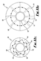
- Figure 10 shows a further alternative embodiment of the invention, generally depicted at 140.
- the apertures 144 and the swellable mantle 146 are longitudinal grooves, at the inserts 146 are formed from blocks of sintered metal material.
- the blocks of sintered metal material are overlaid with screen sections 148 before filtering solids from fluid flowing through the apertures 144 and into the main body.
- the swellable mantle expands outwardly and partially over the screen section, but without covering the aperture to prevent fluid flow.
- the apertures 144 are helical or circumferential slots or holes in the swellable mantle.
- FIG. 11A and 11B A further alternative embodiment is shown in Figures 11A and 11B .
- a substantially tubular screen 152 is embedded into a swellable mantle 153.
- Apertures 158 are provided in the mantle 153 to allow fluid flow to the main body 159.
- the screen 152 comprises longitudinal support members 154 which function to provide support to the relatively flexible screen material 156.
- the screen material is folded, bent or creased to such that is radial dimension is less than the maximum radial dimension which can be defined by the screen 152.
- the screen has a fixed surface area, but is embedded into the swellable mantle such that it may expand radially on expansion of the swellable material to a position shown in Figure 13B, without stretching the screen material or affecting the filter grade.
- the apertures, or selected apertures in the swellable mantle are provided with flow control members such as valves or check valves to restrict fluid flow therethrough.
- the present invention in its various aspects provides an improved and alternative downhole apparatus and method offering improved performance and/ or wider operating parameters than the apparatus of the prior art.
Abstract
Description
- The present invention relates to a downhole apparatus and method for use in the completion of hydrocarbon wells, and in one aspect to a downhole screen including a swellable material and a method of use.
- In the completion of hydrocarbon wells, it is known to use screens to prevent the production of solids from the formation. Expandable tubular technology has been used to expand metal screens to reduce the annular space around the screen and thereby reduce or eliminate the requirement for gravel packing and provide structural support for the formation.
- There are a number of drawbacks to using expanding tubulars. It can be difficult to control the force used to expand the tubular, and there may be resulting problems with the application of an undue, damaging force onto the formation. Expandable tubulars also have a limited expansion range, which means that maximum expansion can still result in an unsupported formation in a wash out zone.
-
US 2005/0173130 describes an arrangement in which a swellable layer is located over an expanding screen to allow the apparatus to conform to the borehole shape. Holes in the swellable layer allow the passage of formation fluids. However, it is desirable in many applications to avoid the use of expanding tubulars. Additionally, by providing the screen around the expandable pipe at a location displaced from the borehole wall, there is an annular space into which solids may be produced, and along which solids may flow. This increases the risk of blocking the screen and creating so-called hotspots which are prone to erosion. - The proposal of
WO 2006/003112 attempts to overcome these deficiencies by providing a screen which is expanded into contact with the borehole wall by swellable rings. This approach relies on overlaid screen sheets which are forced outward by the swelling of the rings. This has the undesirable effect of restraining expansion of the swellable material, which may only be capable of exerting a pressure of 50 to 100 PSI (345 to 690 KPa). In addition, the gaps between overlaid screen sheets provide route for solid particles to enter the production tubing. - It is one aim of at least one aspect the invention to provide a downhole apparatus and method which overcomes or mitigates the deficiencies of previously proposed apparatus and methods.
- It is another aim of at least one aspect of the invention to provide an alternative apparatus and method to those previously proposed.
- It is an aim of at least one aspect of the invention to provide a downhole apparatus offering improved performance and or wider operating parameters than the apparatus of the prior art.
- According to a first aspect of the invention there is provided a downhole apparatus comprising a main body having a bore arranged to be coupled with a well tubing; and a swellable mantle disposed on the main body, which swellable mantle expands upon contact with at least one predetermined fluid; wherein the main body comprises at least one opening for fluid flow between an exterior of the main body and the bore, and the swellable mantle is provided with an insert to permit the passage of fluid between the exterior of the apparatus and the at least one opening through the swellable mantle.
- Thus the apparatus may permit fluid flow from its exterior into the bore, through the openings in the main body, and onward to the well tubing. The apparatus may therefore communicate with production tubing, and may be adapted to permit flow of production fluid from a producing zone into the production tubing.
- The swellable mantle may be disposed around an elongate portion of the main body, and may form a substantially cylindrical member around the main body. The elongate portion may comprise at least one opening therein, and the swellable mantle may be adapted to allow the passage of fluid between the exterior of the apparatus and the at least one opening in the elongate portion. The apparatus may therefore be arranged to permit fluid flow across an area or surface over which the swellable mantle is disposed.
- The main body may be a tubular, and may form a base pipe of the apparatus. The main body may comprise a liner tubular. Preferably, the main body comprises a plurality of openings. The openings may be slots or perforations. The main body may therefore be a slotted or pre-perforated tubular.
- In a preferred embodiment, the main body is formed to a fixed diameter, and is not adapted for expansion in use.
- The swellable mantle may be provided with at least one formation to promote fluid flow between the exterior of the apparatus and the at least one opening.
- Preferably, the swellable mantle is provided with at least one aperture therein. The aperture may be a hole, groove or slot in the swellable mantle. The aperture may be a radial opening in the swellable mantle. The aperture may comprise a groove extending circumferentially of the swellable mantle, and may comprise an annular groove in the swellable mantle. Alternatively, or in addition, the aperture may comprise a groove extending longitudinally of the swellable mantle. The aperture may comprise a groove defining a groove axis, which may be oriented longitudinally, circumferentially, or helically of the swellable mantle.
- The aperture may comprise a hole extending radially of the swellable mantle.
- The aperture may provide a fluid flow path from the exterior of the apparatus to main body. The apparatus may comprise a flow path from the exterior of the apparatus to the bore, via the aperture and the at least one opening in the main body. The flow path may be from a producing formation to the bore, via the aperture and the at least one opening in the main body.
- The insert may be provided in the aperture. The insert preferably permits fluid flow through the aperture. The insert may be adapted to maintain a flow path in the aperture. The insert may comprise a fluid permeable material. The insert may function as a filter for filtering solid particles from the fluid flowing through the aperture.
- The insert may be disposed over one or more openings of the main body. The insert may extend longitudinally and/ or radially of the main body. The insert may substantially fill a volume defined by the aperture. The insert may function to support or abut a portion of the swellable mantle, and may define a bearing surface for a portion of the swellable mantle. The insert may therefore limit or prevent the expansion of the swellable mantle in at least one direction, and may be arranged to prevent the expansion of the swellable mantle into the flow path defined by the aperture.
- The insert may be formed from a permeable rope, a braided line or a fibrous material, which may be wound into the aperture. Alternatively, the insert may comprise a sintered metal component.
- In a further alternative, the insert may comprise an impermeable metal component having fluid apertures formed therein. The insert may comprise an abrasion-or erosion-resistant material such as tungsten carbide or similar.
- The insert may define a conduit in the swellable mantle. The insert may define a radially extending conduit through an aperture in the swellable mantle. The conduit may be a bounded conduit, which may be adapted to maintain a flow path in the aperture. The conduit may be defined by a tube. The conduit may extend from the exterior of the swellable mantle to main body. The conduit may have a first end arranged for fluid flow to and/ or from an exterior of the apparatus and a second end arranged for fluid flow to and/or from the main body. The second end may be located at or adjacent to the main body. The second end may be coupled to the apparatus at an opening on the main body.
- Alternatively, the second end may fully or partially extend into main body. The second end may be bonded to the main body.
- The conduit may be of variable length. The conduit may be telescopic, and may comprise a first member at the first end, movably coupled to a second member at the second end. The first and second members may therefore move relative to one another to create a channel of variable length. Such relative movement result from expansion of the swellable mantle. The second member may be bonded to the swellable mantle. The first member may be adapted to move relative to the second member on expansion of the swellable mantle. A seal may be provided between the first and second members.
- In an embodiment of the invention, there is provided one or more flow-directing members or channels disposed on an outer surface of the apparatus. The flow-directing member may be adapted to couple multiple apertures, and or direct flow to multiple apertures. The flow-directing member may be provided with holes corresponding to apertures in the swellable mantle. The flow-directing member may provide a fluid path from the exterior of the apparatus to one or more apertures. The flow-directing member may be coupled to an insert to an aperture.
- Preferably, the flow-directing member is coupled to multiple inserts, and may be integral therewith. More preferably, the flow-directing member is coupled to multiple conduits, or first members thereof. The flow directing member may partially or fully define the inserts to the apertures.
- The flow-directing member and the inserts can be considered in one embodiment to function as a gutter and a series of drainpipes respectively.
- Preferably, the apparatus comprises a screen for filtering solids between the exterior of the apparatus and the bore. Preferably the screen is arranged to filter solids from fluid flowing from the exterior of the apparatus to the bore. The screen functions to filter solids produced from the formation, such as sands or shale or the like, from the fluid. The screen may comprise a plurality of layers. The screen may comprise at least one mesh layer, but preferably comprises a plurality of mesh layers.
- The screen may comprise a filter mesh layer having a filter grade of 50 microns to 350 microns. The screen may further comprise one or both of an outer protective shroud or a drainage support mesh layer. Preferably, the screen comprises a first drainage support mesh layer on one side of a filter mesh layer, and a second drainage support mesh layer on an opposing side of a filter mesh layer.
- The screen is preferably disposed over the openings. More preferably, the screen is disposed over the apertures. The screen may be disposed in the flow directing member.
- The apparatus may comprise multiple screens at discrete locations. The apparatus may comprise at least two screens having different filter grades.
- The swellable mantle is preferably disposed around the main body and may be arranged to expand upon contact with at least one predetermined fluid and thereby move the screen outwardly of the main body. The screen is preferably arranged such that any restraining force imparted by the screen onto the swellable mantle which acts against its expansion can be overcome by the swellable mantle. More preferably, substantially no restraining force is imparted on the swellable mantle by the screen.
- The apparatus may be arranged such that the surface area of the screen is maintained in use, between an unexpanded condition and an expanded condition. The screen may have a screen surface area; and the swellable mantle may be disposed around the main body between the main body and the screen. Preferably, the swellable mantle is arranged to expand upon contact with at least one predetermined fluid and thereby move the outwardly of the main body while maintaining the screen surface area.
- The swellable mantle may comprise a first region located between the main body and the screen which allows the passage of fluid between the exterior of the apparatus and the main body. The swellable mantle may include a second region, which may be circumferentially adjacent the first region, which substantially prevents passage of fluid between the exterior of the apparatus and the main body.
- Preferably, the second region is adapted to be expanded into contact with the borehole wall.
- The screen may be discontinuous around the circumference of the main body. The screen may consist of multiple portions of screening material, which may be discrete in an expanded condition of the apparatus. The multiple portions may additionally be discrete in an unexpanded condition of the apparatus. Preferably, the swellable member is disposed around the main body between the main body and the screen such that on expansion the screen is moved outwardly of the main body. The screen may comprise at least two discrete screens or screen sections circumferentially spaced on the apparatus.
- Preferably, the swellable mantle is disposed between the main body and a borehole wall in use. The apparatus may be adapted to provide stand off of the main body from the bore in the apparatus is located. More preferably the swellable mantle is further adapted to provide support to a wall of the bore in which it is located.
- The apparatus may be used to support a loose or unstable borehole formation, such as a sandstone or shale formation. The apparatus may be adapted for compliant expansion of the swellable mantle to the formation, such that the swellable mantle contacts the formation without unduly stressing the formation. This has the advantage of reducing rock fatigue and reducing the tendency of solids to flow out of the formation with the fluid.
- Although the term "swellable mantle" is used herein it should not be taken to imply a single piece of swellable material unless otherwise specified. Certain embodiments of the invention comprise multiple, separate pieces of swellable material which combine to provide the so-called swellable mantle. Other embodiments comprise a unitary swellable mantle.
- The swellable material may comprise an ethylene-propylene co-polymer cross-linked with at least one of a peroxide and sulphur. More specifically the swellable member may comprise ethylene propylene diene monomer rubber (EPDM).
- Alternatively or in addition the swellable member may contain at least one or multiple water absorbing resins or more precisely any lightly cross-linked hydrophilic polymer embedded within the main swellable member elastomer which may comprise at least one of chloroprene, styrene butadiene or ethylene-propylene rubbers. Such water-absorbing resins are termed "superabsorbent polymers" or "SAPs" and when embedded within the swellable member it may expand when in contact with an aqueous solution.
- Examples of water absorbent resin include cross-linked polyacrylic acid salts, cross-linked copolymers of vinyl alcohol and acrylic acid salt, cross-linked products of polyvinyl alcohol grafted with maleic anhydride, crosslinked copolymers of acrylic acid salt and meth-acrylic acid salt, cross-linked saponification products of methyl acrylate-vinyl acetate copolymer, cross-linked products of starch-acrylic acid salt graft copolymer, crosslinked saponification products of starch-acrylonitrile graft copolymer, crosslinked saponification products of starch-ethyl acrylate graft copolymer, crosslinked carboxymethyl cellulose and the like.
- Alternatively or in addition, the swellable member may comprise an ethylene-propylene-diene polymer with embedded water absorbent resin such that expansion of the swellable member may result from contacting either an aqueous solution or polar liquid such as oil or a mixture of both.
- According to a second aspect of the invention there is provided a well completion or hydrocarbon production method comprising the steps of:
- a. Providing a swellable mantle over an opening on a main body of an apparatus;
- b. Locating the apparatus at a downhole location;
- c. Expanding the swellable mantle by exposing it to a predetermined fluid;
- d. Maintaining a fluid flow path in the swellable mantle using an insert in the swellable mantle;
- e. Allowing fluid flow between an exterior of the apparatus and the at least one opening through the swellable mantle.
- The method may comprise the step of allowing fluid to flow through the insert. The method may comprise the step of receiving fluid from the formation and into a well tubing to which the apparatus is coupled.
- The method may include the additional step of screening solids from the fluid received from the formation.
- The method may include the additional step of moving a screen outwardly of the main body during expansion of the swellable mantle.
- The method may include the step of expanding the swellable mantle without changing the surface area of the screen.
- The method may include the step of expanding the swellable mantle such that the screen consists of a plurality of discrete screen sections after expansion.
- Other preferred and optional features of the second aspect of the invention are defined with respect to the first aspect of the invention.
- According to a third aspect of the invention there is provided downhole apparatus comprising a main body having a bore communicating with a well tubing, and at least one opening for fluid flow between an exterior of the main body and the bore; a screen for filtering solids between the exterior of the apparatus and the bore; and a swellable mantle disposed around the main body and arranged to expand upon contact with at least one predetermined fluid and thereby move the screen outwardly of the main body, wherein the swellable mantle comprises a first region located between the main body and the screen which allows the passage of fluid between the exterior of the apparatus and the main body; and a second region, circumferentially adjacent the first region, which substantially prevents passage of fluid between the exterior of the apparatus and the main body.
- Thus the invention in this aspect provides a swellable mantle with a surface which is designed to permit or prevent fluid flow through circumferentially separated areas. This facilitates the use of a screen which is not continuous around the circumference of swellable mantle. The discontinuous nature of the screen permits the screen to be moved outwardly of the main body more readily than if a continuous screen were used.
- Preferably, the second region is adapted to be expanded into contact with the borehole wall.
- The screen is preferably arranged such that any restraining force imparted by the screen onto the swellable mantle which acts against its expansion can be overcome by the swellable mantle. More preferably, substantially no restraining force is imparted on the swellable mantle by the screen.
- The apparatus may be arranged such that the surface area of the screen is maintained in use, between an unexpanded condition and an expanded condition. The screen may have a screen surface area; and the swellable mantle may be disposed around the main body between the main body and the screen. Preferably, the swellable mantle is arranged to expand upon contact with at least one predetermined fluid and thereby move the outwardly of the main body while maintaining the screen surface area.
- The screen may be discontinuous around the circumference of the main body. The screen may consist of multiple portions of screening material, which may be discrete in an expanded condition of the apparatus. The multiple portions may additionally be discrete in an unexpanded condition of the apparatus. Preferably, the swellable member is disposed around the main body between the main body and the screen such that on expansion the screen is moved outwardly of the main body. The screen may comprise at least two discrete screen sections circumferentially spaced on the apparatus.
- Other preferred and optional features of the third aspect of the invention are defined with respect to the first and second aspects of the invention.
- According to a fourth aspect of the invention there is provided a well completion or hydrocarbon production method comprising the steps of:
- a. Providing a swellable mantle over an opening on a main body of an apparatus;
- b. Locating the apparatus at a downhole location;
- c. Expanding the swellable mantle by exposing it to a predetermined fluid to thereby move a screen outwardly of the main body;
- d. Allowing fluid to flow between an exterior of the apparatus and the at least one opening through a first region of the swellable mantle located between the main body and the screen, while substantially preventing passage of fluid between the exterior of the apparatus and the main body in a second region of the swellable mantle, circumferentially adjacent the first region.
- The method may comprise the step of receiving fluid from the formation and into a well tubing to which the apparatus is coupled.
- The method may include the additional step of screening solids from the fluid received from the formation.
- The method may include the step of expanding the swellable mantle without changing the surface area of the screen.
- The method may include the step of expanding the swellable mantle such that the screen consists of a plurality of discrete screen sections after expansion.
- Other preferred and optional features of the fourth aspect of the invention are defined with respect to the first to third aspects of the invention.
- According to a fifth aspect of the invention there is provided a downhole apparatus comprising a main body having a bore communicating with a well tubing, and at least one opening for fluid flow between an exterior of the main body and the bore; a screen for filtering solids between the exterior of the apparatus and the bore having a screen surface area; and a swellable member disposed around the main body between the main body and the screen, wherein the swellable member is arranged to expand upon contact with at least one predetermined fluid and thereby move the screen outwardly of the main body while maintaining the screen surface area.
- Other preferred and optional features of the fifth aspect of the invention are defined with respect to the first to fourth aspects of the invention.
- According to a sixth aspect of the invention there is provided a downhole apparatus comprising a main body having a bore communicating with a well tubing, and at least one opening for fluid flow between an exterior of the main body and the bore; a screen for filtering solids between the exterior of the apparatus and the bore; and a swellable member disposed around the main body between the main body and the screen, wherein the swellable member is arranged to expand upon contact with at least one predetermined fluid and thereby move the screen outwardly of the main body, wherein the screen comprises at least two discrete screen sections circumferentially spaced on the apparatus.
- Other preferred and optional features of the sixth aspect of the invention are defined with respect to the first to fifth aspects of the invention.
- Use of the first, third, fifth and sixth aspects of the invention in well completion or production methods is within the scope of the invention. A volume of hydrocarbon obtained by using the apparatus or methods described also forms part of the invention.
- There will now be described, by way of example only, various embodiments of the invention with reference to the following drawings, of which:
-
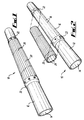
Figure 1 is a perspective view of an apparatus in accordance with a preferred embodiment of the invention; -
Figure 2 is a perspective view of the apparatus ofFigure 1 with the swellable mantle removed to show other components; -
Figure 3 is an exploded view of the swellable mantle of the apparatus ofFigures 1 and 2 ; -
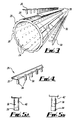
Figure 4 is a perspective view of an insert used with the apparatus ofFigures 1, 2 and3 ; -
Figures 5A and 5B are schematic views of the insert ofFigure 4 in retracted and extended conditions respectively; -
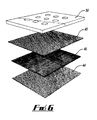
Figure 6 is a schematic exploded view of a filter used in accordance with embodiments of the invention; -
Figure 7 is a schematic sectional view of the apparatus ofFigure 1 in use in a wellbore; -
Figure 8 is a schematic representation of apparatus in accordance with an alternative embodiment of the invention in partial longitudinal section; -
Figure 9 is a schematic representation of apparatus in accordance with a second embodiment of the invention in partial longitudinal section; -
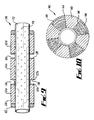
Figure 10 is a cross-sectional view of apparatus in accordance with a further embodiment of the invention; -
Figure 11A is a cross-sectional view of apparatus in accordance with a further embodiment of the invention; and -
Figure 11B is a cross-sectional view of the apparatus ofFigure 11A in an expanded configuration. - Referring firstly to
Figures 1 to 3 , there is shown a downhole apparatus, generally depicted at 10, in accordance with an embodiment of the invention. Theapparatus 10 comprises amain body 12 formed from tubular base pipe. Thebody 12 is adapted to be coupled to well tubing (not shown) such that thebore 14 of the apparatus communicates with the bore of the well tubing. - A
section 16 of themain body 12 extending over a length of the apparatus is provided withopenings 18 or perforations distributed longitudinally and circumferentially on thesection 16. The openings are through-openings from an exterior of themain body 12 to thebore 14. In this embodiment, theopenings 18 are regularly distributed, although in alternative embodiments other arrangements of openings may be provided. - Disposed over the
main body 12 is aswellable mantle 20.Figure 2 shows the mantle removed from theapparatus 10. Theswellable mantle 20 is a substantially tubular member shaped to fit over thesection 16 of the apparatus. The swellable mantle is sized to be bonded or slipped onto the main body, and is located on thesection 16 by end rings 22. The end rings 22 are secured to the main body to prevent axial and radial movement and to abut the respective ends of theswellable mantle 20. - The
swellable mantle 20 is provided withapertures 24 and inserts 26 to the apertures. Theinserts 26 are located in longitudinal recessedgrooves 28 on the outer surface of theswellable mantle 20. Theinserts 26 will be described in more detail below. - The
swellable mantle 20 is formed from a material which is selected to expand on contact with a predetermined fluid. Such swellable materials are known in the art. In this example, the swellable mantle is required to swell in oil, and the material comprises ethylene propylene diene monomer rubber (EPDM). In an alternative embodiment, where the swellable mantle is required to swell in water, the material comprises any lightly crosslinked hydrophilic polymer embedded within the main swellable member elastomer, such as at least one of chloroprene, styrene butadiene or ethylene-propylene rubbers. Such water-absorbing resins are termed "superabsorbent polymers" or "SAPs" and when embedded within the swellable member may expand when in contact with an aqueous solution. In a further alternative embodiment, the swellable member comprises an ethylene-propylene diene polymer with embedded water absorbent resin such that expansion of the swellable member results from contacting either an aqueous solution or polar liquid such as oil or a mixture of both. - The
apertures 24 function to allow fluid to flow from the exterior of theswellable mantle 20 to its interior. When the swellable mantle is positioned on themain body 12, theapertures 24 allow fluid flow from the exterior of the apparatus to themain body 12 and through theopenings 18 in the main body to thebore 14. In this embodiment, the spacing of theapertures 24 corresponds to the spacing of theopenings 18, such that theapertures 24 andopenings 18 may be aligned to provide minimal resistance to fluid flow from the exterior of the apparatus to thebore 14. - The
swellable mantle 20 functions to expand on contact with a well bore fluid such that the outer surface of the apparatus comes into contact with the borehole wall. The dimensions and properties of the swellable mantle are selected for compliant expansion of the swellable mantle into contact with the borehole wall, such that an appropriately low force is imparted to the borehole to create a seal, but to prevent damage to the rock formation or sandface. The dimensions and material of the swellable mantle are also selected to expand into a washout zone in the borehole to similarly create a seal with a suitably low force on the formation. In this way, the formation is supported from collapse towards themain body 12, but without damaging the formation in a way that would increase the inflow of solids. - The insert includes a
screen support 30 andscreen material 32. Theinsert 26 therefore definesscreen sections 33 of the apparatus along circumferentially spaced longitudinal regions of theswellable mantle 20. Disposed between the screen sections are longitudinal regions of theswellable mantle 20 which substantially prevent fluid flow to the interior of themantle 20. In this regard, it is noted that the swellable material may permit fluid penetration by diffusion through the swellable material, but does not permit fluid flow such as that required for the inflow of production fluids into thebore 14 or the injection of fluids from thebore 14 into the formation. -
Figures 4, 5A and 5B show theinsert 26 in more detail, with thescreen material 32 removed. Theinsert 26 includes a plurality ofconduits 34 which extend through the swellable mantle to the main body. Multiple conduits are connected by achannel 35 defined by thescreen support 30. Theconduits 34 each comprise afirst member 36 received in asecond member 38. The first andsecond members swellable mantle 20. The conduits function to maintain the flow path of the aperture after expansion. In alternative embodiments of the invention, the conduits, or a subset of conduits, are provided with flow control members such as valves or check valves to restrict fluid flow therethrough. - When assembled, the
second member 38 is an interference fit with theaperture 24 of the swellable mantle into which it locates. Theundersurface 42 of thescreen support 30 is bonded to the surface of theswellable mantle 20 along thelongitudinal groove 28. When the swellable mantle expands, thefirst member 36 moves relative to thesecond member 38 such that the conduit telescopically extends. - In alternative embodiments, the
second member 38 may be fixed to themain body 12 and/or may be received in theopening 18 in the main body. - Referring now to
Figure 6 , thescreen material 32 is shown as comprising a plurality of overlaid layers. Adjacent thescreen support 30 is provided adrainage support mesh 44, onto which is overlaid afilter mesh 46. The filter mesh is selected to have an appropriate mesh grade for filtering solids which may be produced from the formation. Typically, the filter mesh will have a mesh grade of around 100 to 300 microns. Over thefilter mesh 46 is a furtherdrainage support mesh 48, and finally an outerprotective shroud 50, having relatively large apertures, is provided on the exterior of the screen material. - The present invention encapsulates embodiments in which different screen sections are provided with different filter grades. The invention also facilitates customisation of the apparatus by selecting appropriate filter grades during assembly of the apparatus.
-
Figure 7 shows theapparatus 10 in use in a borehole, in a swelled condition. Theapparatus 10 has been run to a location in a sand-producingformation 51, and exposure to wellbore fluids has caused theswellable mantle 20 to expand into contact with theborehole wall 52. As expansion takes place, theconduits 34 defined by theinserts 26 telescopically extend such that a bounded conduit is formed between the exterior of the apparatus and theopenings 18 in themain body 12. The inserts prevent theswellable mantle 20 from expanding to close theapertures 24. - The
screen sections 33 are placed adjacent to the sandface by expansion of the swellable mantle under the insert, andadjacent regions 54 of the swellable mantle form a compliant seal on theborehole wall 52. Fluid flow from the formation is permitted in the areas at which thescreen sections 32 are provided, and is directed through theapertures 24, via theconduits 34, and into thebore 14. Flow is not permitted through theregions 54. - This embodiment of the invention provides compliant expansion of a swellable member to a borehole wall, providing structural support to the borehole without damaging the sandface. The
screen sections 33 are carried or moved in a radial direction to be placed adjacent to the sandface. This minimises the annular space in which solids produced from the formation can flow. The flow of fluid is only permitted in the regions at which the screen material is provided, with adjacent sections supported and sealed by the swellable mantle. By providing the plurality of discrete screen sections, movement of the screen outwardly from the main body of the apparatus is accomplished effectively without restraining swelling of the mantle. The embodiment of the invention is also conducive to customisation and configuration of the filter grades used, which may differ between screen sections. - There will now be described alternative embodiments of the invention with reference to
Figures 8 to 11 . - Referring to
Figure 8 , there is shown a downhole apparatus, generally depicted at 100 consisting of themain body 112 formed from a tubular base pipe and adapted to be coupled to well tubing in the same manner asapparatus 10. In a similar fashion toapparatus 10, themain body 112 is provided with a plurality of through-openings 118 distributed on the body. - Disposed on the
body 112, and shown in the Figure in longitudinal section, areend rings 122 and aswellable mantle 120 consisting of three longitudinally spacedsections Apertures 124 are provided in the form of circumferential grooves to theswellable mantle 120 extending from its outer surface to themain body 112. Provided in theapertures 124 areinserts 126, which in this embodiment are constructed from a permeable rope which is wound around the main body into the aperture. Theinsert 126 is wound tightly on the main body and provides an abutting surface for the adjacent portions of theswellable mantle 120. In use, the swellable mantle expands outwardly and partially over theinsert 126, but without covering the aperture to prevent fluid flow. - The
inserts 126 function to permit fluid flow through the aperture and into the main body, while maintaining the flow path and limiting or preventing the expansion of the swellable mantle in the longitudinal direction. The insert additionally functions as a filter for solid particles in the fluid flowing through the aperture. - In an alternative embodiment, the
insert 126 is wound from a braided line or wire, or a fibrous material. -
Figure 9 shows an alternative embodiment, generally depicted at 130, similar to the embodiment ofFigure 8 and with like components identified by like reference numerals. This embodiment differs in the form of theinserts apertures 124. -
Insert 136 is in the form of a cylinder sized to slip onto themain body 112, and provided with first andsecond flange members insert 136 to allow fluid flow to the main body. Theflange members aperture 124.Insert 138 consists of a pair of flange portions extending outwardly from the main body, and exposing the main body to theaperture 124. - In this embodiment, one or both of the inserts of 136, 138 may comprise a hardened, erosion-resistant material such as tungsten carbide. This functions to resist erosion caused by solid particles contained in the fluid, which would have a tendency to erode the swellable mantle and/or the openings in the
main body 112. It will be appreciated that the apparatus may comprise only one type of theinserts -
Figure 10 shows a further alternative embodiment of the invention, generally depicted at 140. In this embodiment, theapertures 144 and theswellable mantle 146 are longitudinal grooves, at theinserts 146 are formed from blocks of sintered metal material. The blocks of sintered metal material are overlaid withscreen sections 148 before filtering solids from fluid flowing through theapertures 144 and into the main body. In use, the swellable mantle expands outwardly and partially over the screen section, but without covering the aperture to prevent fluid flow. In alternative embodiments, theapertures 144 are helical or circumferential slots or holes in the swellable mantle. - A further alternative embodiment is shown in
Figures 11A and 11B . In this embodiment, shown generally at 150, a substantiallytubular screen 152 is embedded into aswellable mantle 153.Apertures 158 are provided in themantle 153 to allow fluid flow to themain body 159. Thescreen 152 compriseslongitudinal support members 154 which function to provide support to the relativelyflexible screen material 156. In Figure 13A, the screen material is folded, bent or creased to such that is radial dimension is less than the maximum radial dimension which can be defined by thescreen 152. The screen has a fixed surface area, but is embedded into the swellable mantle such that it may expand radially on expansion of the swellable material to a position shown in Figure 13B, without stretching the screen material or affecting the filter grade. - Variations to the above-described embodiments are within the scope of the invention. For example, any of the described insert configurations could be used in combination on the same apparatus in the scope of the invention. Combinations of features other than those expressly claimed are within the scope of the invention.
- In further alternative embodiments of the invention, the apertures, or selected apertures in the swellable mantle, are provided with flow control members such as valves or check valves to restrict fluid flow therethrough.
- The present invention in its various aspects provides an improved and alternative downhole apparatus and method offering improved performance and/ or wider operating parameters than the apparatus of the prior art.
- The present application is a divisional application relating to earlier filed European patent application number
08736927.8 PCT/GB2008/001256 -
- A. A downhole apparatus comprising: a main body having a bore arranged to be coupled with a well tubing and a swellable mantle disposed on the main body, which swellable mantle expands upon contact with at least one predetermined fluid; wherein the main body comprises at least one opening for fluid flow between an exterior of the main body and the bore, and the swellable mantle is provided with an insert to permit the passage of fluid, through the swellable mantle, between the exterior of the apparatus and the at least one opening in the main body.
- B. The apparatus of clause A wherein the main body comprises a plurality of openings.
- C. The apparatus of clause A or clause B wherein the swellable mantle is provided with at least one aperture therein.
- D. The apparatus of clause C wherein the insert is provided in the aperture.
- E. The apparatus of any preceding clause wherein the insert is disposed over one or more openings of the main body.
- F. The apparatus of any preceding clause wherein the insert functions as a filter for filtering solid particles from the fluid flowing through the aperture.
- G. The apparatus of any preceding clause wherein the insert functions to limit the expansion of the swellable mantle in at least one direction
- H. The apparatus of any preceding clause wherein the insert comprises an impermeable metal component having fluid apertures formed therein.
- I. The apparatus of any preceding clause wherein the insert comprises an abrasion-or erosion-resistant material.
- J. The apparatus of any preceding clause wherein the insert comprises a sintered metal component.
- K. The apparatus of any of clauses C to J wherein the insert comprises an elongate material wound into the aperture.
- L. The apparatus of clause K wherein the insert is selected from one of a permeable rope, a braided line or a fibrous material.
- M. The apparatus of any of clauses C to L wherein the insert defines a radially extending conduit through an aperture in the swellable mantle.
- N. The apparatus of clause M wherein the conduit comprises a first end adjacent the exterior of the apparatus and a second end adjacent the main body.
- O. The apparatus of clause M or clause N wherein the conduit is of variable length.
- P. The apparatus of clause O wherein the conduit is telescopic, and comprises a first member at the first end, movably coupled to a second member at the second end.
- Q. The apparatus of clause P wherein the first member is adapted to move relative to the second member on expansion of the swellable mantle.
- R. The apparatus of clause P or clause Q wherein a seal is provided between the first and second members.
- S. The apparatus of any preceding clause further comprising one or more flow-directing members disposed on an outer surface of the apparatus.
- T. The apparatus of clause S wherein the flow-directing member provides a fluid path from the exterior of the apparatus to one or more apertures in the swellable mantle.
- U. The apparatus of clause S or clause T wherein the flow-directing member is coupled to the insert.
- V. The apparatus of clause U wherein the apparatus comprises multiple inserts, and the flow-directing member is coupled to multiple inserts.
- W. The apparatus of any of clauses S to V wherein the insert comprises a part of the flow directing member.
- X. The apparatus of any preceding clause further comprising a screen for filtering solids between the exterior of the apparatus and the bore.
- Y. The apparatus of clause X wherein the screen comprises a filter mesh layer having a filter grade of 50 microns to 350 microns.
- Z. The apparatus of clause X or clause Y when dependent on clause C wherein the screen is disposed over the apertures.
- AA. The apparatus of any of clauses X to Z when dependent on any of clauses S to W, wherein the screen is disposed in the flow-directing member.
- BB. The apparatus of any of clauses X to AA wherein the screen is discontinuous around a circumference of the main body.
- CC. The apparatus of any of clauses X to BB comprising multiple screens at discrete locations.
- DD. The apparatus of clause CC wherein the screen comprises at least two discrete screen sections circumferentially spaced on the apparatus.
- EE. The apparatus of clause CC or clause DD further comprising at least two screens or screen sections having different filter grades.
- FF. The apparatus of any of clauses X to EE wherein the swellable mantle is disposed around the main body and is arranged to expand upon contact with at least one predetermined fluid and thereby move the screen outwardly of the main body.
- GG. The apparatus of clause FF wherein the screen has a screen surface area; and the swellable mantle is arranged to move the screen outwardly of the main body while maintaining the screen surface area.
- HH. The apparatus of any of clauses X to GG wherein the swellable mantle comprises a first region located between the main body and the screen which allows the passage of fluid between the exterior of the apparatus and the main body; and a second region, circumferentially adjacent the first region, which substantially prevents passage of fluid between the exterior of the apparatus and the main body.
- II. The apparatus of clause HH wherein the second region is adapted to be expanded into contact with a borehole wall.
- JJ. A well completion method comprising the steps of:
- a. Providing a swellable mantle over an opening on a main body of an apparatus;
- b. Locating the apparatus at a downhole location;
- c. Expanding the swellable mantle by exposing it to a predetermined fluid;
- d. Maintaining a fluid flow path in the swellable mantle using an insert in the swellable mantle.
- KK. The method of clause JJ comprising the additional step of moving a screen outwardly of the main body during expansion of the swellable mantle.
- LL. The method of clause KK comprising the additional step of expanding the swellable mantle without changing the surface area of the screen.
- MM. The method of clause KK or clause LL comprising the additional step of expanding the swellable mantle such that the screen consists of a plurality of discrete screen sections after expansion.
- NN. A hydrocarbon production method comprising the steps of:
- a. Providing a well completion by the method of any of clauses JJ to MM, and;
- b. Allowing fluid to flow through the swellable mantle between an exterior of the apparatus and the at least one opening in the main body.
- OO. The method of clause NN comprising the additional step of allowing fluid to flow through the insert.
- PP. The method of clause NN or clause OO comprising the additional step of receiving fluid from the formation into a production tubing to which the apparatus is coupled.
- QQ. A downhole apparatus comprising a main body having a bore communicating with a well tubing, and at least one opening for fluid flow between an exterior of the main body and the bore; a screen for filtering solids between the exterior of the apparatus and the bore; and a swellable mantle disposed around the main body and arranged to expand upon contact with at least one predetermined fluid and thereby move the screen outwardly of the main body, wherein the swellable mantle comprises a first region located between the main body and the screen which allows the passage of fluid between the exterior of the apparatus and the main body; and a second region, circumferentially adjacent the first region, which substantially prevents passage of fluid between the exterior of the apparatus and the main body.
- RR. The apparatus of clause QQ wherein the second region is adapted to be expanded into contact with the borehole wall.
- SS. The apparatus of clause QQ or clause RR wherein the screen has a screen surface area, and the swellable mantle is arranged to move the screen outwardly of the main body while maintaining the screen surface area.
- TT. The apparatus of any of clauses QQ to SS wherein the screen is discontinuous around the circumference of the main body.
- UU. The apparatus of any of clauses QQ to TT wherein the screen consists of multiple portions of screen material which are discrete in an expanded condition of the apparatus.
- VV. The apparatus of clause UU wherein the multiple portions are discrete in an unexpanded condition of the apparatus.
- WW. The apparatus of any of clauses QQ to VV wherein the screen comprises at least two discrete screen sections circumferentially spaced on the apparatus.
- XX. The apparatus of any of clauses UU to WW wherein the apparatus comprises at least two screens or screen sections having different filter grades.
- YY. The apparatus of any of clauses QQ to XX wherein an insert is provided in an aperture in the swellable mantle.
- ZZ. The apparatus of clause YY wherein the insert functions to limit the expansion of the swellable mantle in at least one direction.
- AAA. A well completion method comprising the steps of:
- a. Providing a swellable mantle over an opening on a main body of an apparatus, the swellable mantle comprising a first region located between the main body and the screen which allows the passage of fluid between the exterior of the apparatus and the main body; and a second region, circumferentially adjacent the first region, which substantially prevents passage of fluid between the exterior of the apparatus and the main body;
- b. Locating the apparatus at a downhole location, and;
- c. Expanding the swellable mantle by exposing it to a predetermined fluid to thereby move a screen outwardly of the main body.
- BBB. The method of clause AAA comprising the additional step of expanding the swellable mantle without changing the surface area of the screen.
- CCC. The method of clause AAA or clause BBB comprising the additional step of expanding the swellable mantle such that the screen consists of a plurality of discrete screen sections after expansion.
- DDD. A hydrocarbon production method comprising the steps of:
- a. Providing a well completion by the method of any of clauses AAA to CCC, and;
- b. Allowing fluid to flow through the swellable mantle between an exterior of the apparatus and the at least one opening in the main body.
- EEE. The method of clause DDD, comprising the additional step of allowing fluid to flow between an exterior of the apparatus and the at least one opening through the first region of the swellable mantle located between the main body and the screen, while substantially preventing passage of fluid between the exterior of the apparatus and the main body in the second region of the swellable mantle, circumferentially adjacent the first region.
- FFF. The method of clause DDD or clause EEE comprising the additional step of receiving fluid from the formation and into a well tubing to which the apparatus is coupled.
- GGG. The method of clause FFF comprising the additional step of screening solids from the fluid received from the formation.
Claims (15)
- A downhole apparatus comprising a main body having a bore communicating with a well tubing, and at least one opening for fluid flow between an exterior of the main body and the bore; a screen for filtering solids between the exterior of the apparatus and the bore; and a swellable mantle disposed around the main body and arranged to expand upon contact with at least one predetermined fluid and thereby move the screen outwardly of the main body, wherein the swellable mantle comprises a first region located between the main body and the screen which allows the passage of fluid between the exterior of the apparatus and the main body; and a second region, circumferentially adjacent the first region, which substantially prevents passage of fluid between the exterior of the apparatus and the main body.
- The apparatus as claimed in claim 1 wherein the second region is adapted to be expanded into contact with the borehole wall.
- The apparatus as claimed in claims 1 or claim 2 wherein the screen comprises at least two discrete screen sections circumferentially spaced on the apparatus.
- The apparatus as claimed in any of claims 1 to 3 further comprising an insert located in an aperture in the swellable mantle, wherein the insert defines a radially extending conduit through the aperture and wherein the conduit is of variable length.
- The apparatus as claimed in any preceding claim further comprising one or more flow-directing members disposed on an outer surface of the apparatus.
- The apparatus as claimed in claim 5 wherein the flow-directing member provides a fluid path from the exterior of the apparatus to one or more apertures in the swellable mantle.
- The apparatus as claimed in claim 5 or claim 6 when dependent on claim 4 wherein the flow-directing member is coupled to the insert.
- The apparatus as claimed in any of claims 5 to 7 wherein the screen is disposed in the flow-directing member.
- The apparatus as claimed in any preceding claim wherein the screen has a screen surface area; and wherein the swellable mantle is disposed around the main body and is arranged to expand upon contact with at least one predetermined fluid and thereby move the screen outwardly of the main body while maintaining the screen surface area.
- A well completion method comprising the steps of:- providing an apparatus at a downhole location, the apparatus comprising a swellable mantle over an opening on a main body of the apparatus;- expanding the swellable mantle by exposing it to a predetermined fluid to thereby move a screen outwardly of the main body;- allowing fluid to flow between an exterior of the apparatus and the at least one opening through a first region of the swellable mantle located between the main body and the screen, while substantially preventing passage of fluid between the exterior of the apparatus and the main body in a second region of the swellable mantle, circumferentially adjacent the first region.
- The method as claimed in claim 10 comprising the additional step of expanding the swellable mantle without changing the surface area of the screen.
- The method as claimed in claim 10 or claim 11 comprising the additional step of expanding the swellable mantle such that the screen consists of a plurality of discrete screen sections after expansion.
- A hydrocarbon production method comprising the steps of:- providing a well completion by the method of any of claims 10 to 12, and;- allowing fluid to flow through the swellable mantle between an exterior of the apparatus and the at least one opening in the main body.
- The method as claimed in claim 13 comprising the additional step of receiving fluid from a formation and into a well tubing to which the apparatus is coupled.
- The method as claimed in claim 14 comprising the additional step of screening solids from the fluid received from the formation.
Priority Applications (3)
| Application Number | Priority Date | Filing Date | Title |
|---|---|---|---|
| PL11158362T PL2339111T3 (en) | 2007-04-10 | 2008-04-10 | Downhole apparatus and method |
| EP12166311.6A EP2484864B1 (en) | 2007-04-10 | 2008-04-10 | Downhole apparatus and method |
| PL12166311T PL2484864T3 (en) | 2007-04-10 | 2008-04-10 | Downhole apparatus and method |
Applications Claiming Priority (2)
| Application Number | Priority Date | Filing Date | Title |
|---|---|---|---|
| GB0706909A GB2448298B (en) | 2007-04-10 | 2007-04-10 | Downhole apparatus and method |
| EP08736927A EP2142756B1 (en) | 2007-04-10 | 2008-04-10 | Downhole apparatus and method |
Related Parent Applications (1)
| Application Number | Title | Priority Date | Filing Date |
|---|---|---|---|
| EP08736927.8 Division | 2008-04-10 |
Related Child Applications (2)
| Application Number | Title | Priority Date | Filing Date |
|---|---|---|---|
| EP12166311.6A Division EP2484864B1 (en) | 2007-04-10 | 2008-04-10 | Downhole apparatus and method |
| EP12166311.6 Division-Into | 2012-05-01 |
Publications (4)
| Publication Number | Publication Date |
|---|---|
| EP2339111A2 true EP2339111A2 (en) | 2011-06-29 |
| EP2339111A3 EP2339111A3 (en) | 2011-07-06 |
| EP2339111B1 EP2339111B1 (en) | 2013-07-10 |
| EP2339111B8 EP2339111B8 (en) | 2013-09-18 |
Family
ID=38091115
Family Applications (3)
| Application Number | Title | Priority Date | Filing Date |
|---|---|---|---|
| EP12166311.6A Not-in-force EP2484864B1 (en) | 2007-04-10 | 2008-04-10 | Downhole apparatus and method |
| EP08736927A Not-in-force EP2142756B1 (en) | 2007-04-10 | 2008-04-10 | Downhole apparatus and method |
| EP11158362.1A Not-in-force EP2339111B8 (en) | 2007-04-10 | 2008-04-10 | Downhole apparatus and method |
Family Applications Before (2)
| Application Number | Title | Priority Date | Filing Date |
|---|---|---|---|
| EP12166311.6A Not-in-force EP2484864B1 (en) | 2007-04-10 | 2008-04-10 | Downhole apparatus and method |
| EP08736927A Not-in-force EP2142756B1 (en) | 2007-04-10 | 2008-04-10 | Downhole apparatus and method |
Country Status (8)
| Country | Link |
|---|---|
| US (1) | US8336619B2 (en) |
| EP (3) | EP2484864B1 (en) |
| AT (1) | ATE510997T1 (en) |
| BR (1) | BRPI0806255B1 (en) |
| CA (1) | CA2683342C (en) |
| GB (2) | GB2448298B (en) |
| PL (3) | PL2142756T3 (en) |
| WO (1) | WO2008122809A1 (en) |
Cited By (1)
| Publication number | Priority date | Publication date | Assignee | Title |
|---|---|---|---|---|
| CN104863549A (en) * | 2015-04-10 | 2015-08-26 | 天津欧派卡石油管材有限公司 | Petroleum screen pipe |
Families Citing this family (24)
| Publication number | Priority date | Publication date | Assignee | Title |
|---|---|---|---|---|
| US20090126947A1 (en) * | 2007-05-31 | 2009-05-21 | Baker Hughes Incorporated | Swellable material and method |
| GB0711979D0 (en) * | 2007-06-21 | 2007-08-01 | Swelltec Ltd | Method and apparatus |
| US8540032B2 (en) * | 2007-06-21 | 2013-09-24 | Swelltec Limited | Apparatus and method with hydrocarbon swellable and water swellable body |
| US7913755B2 (en) * | 2007-10-19 | 2011-03-29 | Baker Hughes Incorporated | Device and system for well completion and control and method for completing and controlling a well |
| US7703520B2 (en) | 2008-01-08 | 2010-04-27 | Halliburton Energy Services, Inc. | Sand control screen assembly and associated methods |
| US7712529B2 (en) | 2008-01-08 | 2010-05-11 | Halliburton Energy Services, Inc. | Sand control screen assembly and method for use of same |
| US8555958B2 (en) | 2008-05-13 | 2013-10-15 | Baker Hughes Incorporated | Pipeless steam assisted gravity drainage system and method |
| US8171999B2 (en) | 2008-05-13 | 2012-05-08 | Baker Huges Incorporated | Downhole flow control device and method |
| US7866383B2 (en) | 2008-08-29 | 2011-01-11 | Halliburton Energy Services, Inc. | Sand control screen assembly and method for use of same |
| US7841409B2 (en) | 2008-08-29 | 2010-11-30 | Halliburton Energy Services, Inc. | Sand control screen assembly and method for use of same |
| US7814973B2 (en) * | 2008-08-29 | 2010-10-19 | Halliburton Energy Services, Inc. | Sand control screen assembly and method for use of same |
| US8302680B2 (en) | 2009-08-12 | 2012-11-06 | Halliburton Energy Services, Inc. | Swellable screen assembly |
| US8256510B2 (en) * | 2009-08-12 | 2012-09-04 | Halliburton Energy Services, Inc. | Control screen assembly |
| US20130206393A1 (en) * | 2012-02-13 | 2013-08-15 | Halliburton Energy Services, Inc. | Economical construction of well screens |
| EP2904191B1 (en) * | 2013-02-06 | 2019-09-25 | Halliburton Energy Services, Inc. | High flow area swellable cementing packer |
| US9416633B2 (en) | 2013-04-30 | 2016-08-16 | Baker Hughes Incorporated | Screen assembly |
| US9970269B2 (en) * | 2013-06-28 | 2018-05-15 | Halliburton Energy Services, Inc. | Expandable well screen having enhanced drainage characteristics when expanded |
| GB2519123B (en) | 2013-10-10 | 2017-07-05 | Amity Luggage And Bags Ltd | Expandable luggage item |
| CA2964218C (en) | 2014-10-28 | 2019-09-17 | Halliburton Energy Services, Inc. | Downhole state-machine-based monitoring of vibration |
| US10267447B2 (en) * | 2015-08-12 | 2019-04-23 | Harris Corporation | Fluid pipe assembly including length compensator and related methods |
| US10858916B2 (en) | 2017-05-01 | 2020-12-08 | Halliburton Energy Services, Inc. | Biflex with flow lines |
| WO2019040695A1 (en) * | 2017-08-24 | 2019-02-28 | Clifford Wayne Hunter | Artificial porosity-pressure adjustable formation fluid-gas control system and method |
| SG10201708842QA (en) * | 2017-10-27 | 2019-05-30 | Galileo Innovations Pte Ltd | Conformance screen assembly |
| US11231136B2 (en) * | 2019-07-22 | 2022-01-25 | Ronald V. Andronaco | Flangeless coupler fused inside opposing ends of conduits |
Citations (2)
| Publication number | Priority date | Publication date | Assignee | Title |
|---|---|---|---|---|
| US20050173130A1 (en) | 2002-08-23 | 2005-08-11 | Baker Hughes Incorporated | Self-conforming screen |
| WO2006003112A1 (en) | 2004-06-25 | 2006-01-12 | Shell Internationale Research Maatschappij B.V. | Screen for controlling sand production in a wellbore |
Family Cites Families (10)
| Publication number | Priority date | Publication date | Assignee | Title |
|---|---|---|---|---|
| DE29707446U1 (en) | 1997-04-24 | 1998-08-27 | Franz Falke Rohen Strumpffabri | Non-slip stocking |
| KR20010075342A (en) | 1998-09-25 | 2001-08-09 | 데이비드 엠 모이어 | Granular detergent composition having improved appearance and solubility |
| CA2416645C (en) * | 2000-07-21 | 2010-05-04 | Sinvent As | Combined liner and matrix system |
| MY135121A (en) * | 2001-07-18 | 2008-02-29 | Shell Int Research | Wellbore system with annular seal member |
| US7284603B2 (en) * | 2001-11-13 | 2007-10-23 | Schlumberger Technology Corporation | Expandable completion system and method |
| AU2003264283A1 (en) * | 2002-09-06 | 2004-03-29 | Shell Internationale Research Maatschappij B.V. | Wellbore device for selective transfer of fluid |
| US7258166B2 (en) * | 2003-12-10 | 2007-08-21 | Absolute Energy Ltd. | Wellbore screen |
| CA2570057C (en) * | 2004-06-25 | 2013-10-15 | Shell Canada Limited | Screen for controlling inflow of solid particles in a wellbore |
| CA2530969C (en) * | 2004-12-21 | 2010-05-18 | Schlumberger Canada Limited | Water shut off method and apparatus |
| EA014109B1 (en) * | 2006-04-03 | 2010-10-29 | Эксонмобил Апстрим Рисерч Компани | Wellbore method and apparatus for sand and inflow control during well operations |
-
2007
- 2007-04-10 GB GB0706909A patent/GB2448298B/en not_active Expired - Fee Related
-
2008
- 2008-04-10 AT AT08736927T patent/ATE510997T1/en not_active IP Right Cessation
- 2008-04-10 PL PL08736927T patent/PL2142756T3/en unknown
- 2008-04-10 EP EP12166311.6A patent/EP2484864B1/en not_active Not-in-force
- 2008-04-10 PL PL11158362T patent/PL2339111T3/en unknown
- 2008-04-10 EP EP08736927A patent/EP2142756B1/en not_active Not-in-force
- 2008-04-10 BR BRPI0806255-2A patent/BRPI0806255B1/en not_active IP Right Cessation
- 2008-04-10 EP EP11158362.1A patent/EP2339111B8/en not_active Not-in-force
- 2008-04-10 US US12/595,085 patent/US8336619B2/en not_active Expired - Fee Related
- 2008-04-10 WO PCT/GB2008/001256 patent/WO2008122809A1/en active Application Filing
- 2008-04-10 PL PL12166311T patent/PL2484864T3/en unknown
- 2008-04-10 CA CA2683342A patent/CA2683342C/en not_active Expired - Fee Related
-
2009
- 2009-07-27 GB GB0912980A patent/GB2462009B/en not_active Expired - Fee Related
Patent Citations (2)
| Publication number | Priority date | Publication date | Assignee | Title |
|---|---|---|---|---|
| US20050173130A1 (en) | 2002-08-23 | 2005-08-11 | Baker Hughes Incorporated | Self-conforming screen |
| WO2006003112A1 (en) | 2004-06-25 | 2006-01-12 | Shell Internationale Research Maatschappij B.V. | Screen for controlling sand production in a wellbore |
Cited By (1)
| Publication number | Priority date | Publication date | Assignee | Title |
|---|---|---|---|---|
| CN104863549A (en) * | 2015-04-10 | 2015-08-26 | 天津欧派卡石油管材有限公司 | Petroleum screen pipe |
Also Published As
| Publication number | Publication date |
|---|---|
| EP2339111B8 (en) | 2013-09-18 |
| EP2484864B1 (en) | 2014-03-19 |
| GB2462009B (en) | 2010-08-18 |
| PL2484864T3 (en) | 2014-08-29 |
| EP2142756B1 (en) | 2011-05-25 |
| GB0912980D0 (en) | 2009-09-02 |
| GB2448298B (en) | 2009-12-23 |
| BRPI0806255B1 (en) | 2018-04-03 |
| PL2142756T3 (en) | 2011-11-30 |
| US20110042096A1 (en) | 2011-02-24 |
| CA2683342A1 (en) | 2008-10-16 |
| PL2339111T3 (en) | 2013-11-29 |
| EP2142756A1 (en) | 2010-01-13 |
| BRPI0806255A2 (en) | 2011-09-13 |
| GB2448298A (en) | 2008-10-15 |
| EP2484864A2 (en) | 2012-08-08 |
| GB2462009A (en) | 2010-01-27 |
| ATE510997T1 (en) | 2011-06-15 |
| EP2484864A3 (en) | 2012-12-26 |
| EP2339111B1 (en) | 2013-07-10 |
| CA2683342C (en) | 2015-11-17 |
| GB0706909D0 (en) | 2007-05-16 |
| US8336619B2 (en) | 2012-12-25 |
| EP2339111A3 (en) | 2011-07-06 |
| WO2008122809A1 (en) | 2008-10-16 |
Similar Documents
| Publication | Publication Date | Title |
|---|---|---|
| EP2339111B1 (en) | Downhole apparatus and method | |
| US7841409B2 (en) | Sand control screen assembly and method for use of same | |
| RU2317403C2 (en) | Downhole device for selective fluid pumping | |
| US7866383B2 (en) | Sand control screen assembly and method for use of same | |
| EP1759086B1 (en) | Screen for controlling sand production in a wellbore | |
| AU2005259248B2 (en) | Screen for controlling inflow of solid particles in a wellbore | |
| CN101910553B (en) | Sand control screen assembly and method for use of same | |
| US9097105B2 (en) | Swellable screen assembly | |
| EP2295717A2 (en) | Downhole screen assembly | |
| BRPI0823329A2 (en) | WELL BACKGROUND APPARATUS AND WELL COMPLETION METHOD | |
| US11118435B2 (en) | Compliant screen shroud to limit expansion | |
| BRPI0823328A2 (en) | WELL BACKGROUND APPARATUS AND WELL COMPLETION METHOD |
Legal Events
| Date | Code | Title | Description |
|---|---|---|---|
| PUAI | Public reference made under article 153(3) epc to a published international application that has entered the european phase |
Free format text: ORIGINAL CODE: 0009012 |
|
| PUAL | Search report despatched |
Free format text: ORIGINAL CODE: 0009013 |
|
| 17P | Request for examination filed |
Effective date: 20110411 |
|
| AC | Divisional application: reference to earlier application |
Ref document number: 2142756 Country of ref document: EP Kind code of ref document: P |
|
| AK | Designated contracting states |
Kind code of ref document: A2 Designated state(s): AT BE BG CH CY CZ DE DK EE ES FI FR GB GR HR HU IE IS IT LI LT LU LV MC MT NL NO PL PT RO SE SI SK TR |
|
| AK | Designated contracting states |
Kind code of ref document: A3 Designated state(s): AT BE BG CH CY CZ DE DK EE ES FI FR GB GR HR HU IE IS IT LI LT LU LV MC MT NL NO PL PT RO SE SI SK TR |
|
| 17Q | First examination report despatched |
Effective date: 20110620 |
|
| GRAP | Despatch of communication of intention to grant a patent |
Free format text: ORIGINAL CODE: EPIDOSNIGR1 |
|
| GRAS | Grant fee paid |
Free format text: ORIGINAL CODE: EPIDOSNIGR3 |
|
| GRAA | (expected) grant |
Free format text: ORIGINAL CODE: 0009210 |
|
| AC | Divisional application: reference to earlier application |
Ref document number: 2142756 Country of ref document: EP Kind code of ref document: P |
|
| AK | Designated contracting states |
Kind code of ref document: B1 Designated state(s): AT BE BG CH CY CZ DE DK EE ES FI FR GB GR HR HU IE IS IT LI LT LU LV MC MT NL NO PL PT RO SE SI SK TR |
|
| REG | Reference to a national code |
Ref country code: GB Ref legal event code: FG4D |
|
| REG | Reference to a national code |
Ref country code: CH Ref legal event code: EP Ref country code: AT Ref legal event code: REF Ref document number: 621086 Country of ref document: AT Kind code of ref document: T Effective date: 20130715 |
|
| REG | Reference to a national code |
Ref country code: IE Ref legal event code: FG4D |
|
| REG | Reference to a national code |
Ref country code: DE Ref legal event code: R096 Ref document number: 602008025990 Country of ref document: DE Effective date: 20130905 |
|
| RBV | Designated contracting states (corrected) |
Designated state(s): AT BE BG CH CY CZ DE DK EE ES FI FR GR HR HU IE IS IT LI LT LU LV MC MT NL NO PL PT RO SE SI SK TR |
|
| REG | Reference to a national code |
Ref country code: NL Ref legal event code: T3 |
|
| PG25 | Lapsed in a contracting state [announced via postgrant information from national office to epo] |
Ref country code: SI Free format text: LAPSE BECAUSE OF FAILURE TO SUBMIT A TRANSLATION OF THE DESCRIPTION OR TO PAY THE FEE WITHIN THE PRESCRIBED TIME-LIMIT Effective date: 20130710 |
|
| REG | Reference to a national code |
Ref country code: NO Ref legal event code: T2 Effective date: 20130710 |
|
| REG | Reference to a national code |
Ref country code: PL Ref legal event code: T3 |
|
| REG | Reference to a national code |
Ref country code: AT Ref legal event code: MK05 Ref document number: 621086 Country of ref document: AT Kind code of ref document: T Effective date: 20130710 |
|
| REG | Reference to a national code |
Ref country code: LT Ref legal event code: MG4D |
|
| PG25 | Lapsed in a contracting state [announced via postgrant information from national office to epo] |
Ref country code: CY Free format text: LAPSE BECAUSE OF FAILURE TO SUBMIT A TRANSLATION OF THE DESCRIPTION OR TO PAY THE FEE WITHIN THE PRESCRIBED TIME-LIMIT Effective date: 20130724 Ref country code: LT Free format text: LAPSE BECAUSE OF FAILURE TO SUBMIT A TRANSLATION OF THE DESCRIPTION OR TO PAY THE FEE WITHIN THE PRESCRIBED TIME-LIMIT Effective date: 20130710 Ref country code: PT Free format text: LAPSE BECAUSE OF FAILURE TO SUBMIT A TRANSLATION OF THE DESCRIPTION OR TO PAY THE FEE WITHIN THE PRESCRIBED TIME-LIMIT Effective date: 20131111 Ref country code: BE Free format text: LAPSE BECAUSE OF FAILURE TO SUBMIT A TRANSLATION OF THE DESCRIPTION OR TO PAY THE FEE WITHIN THE PRESCRIBED TIME-LIMIT Effective date: 20130710 Ref country code: AT Free format text: LAPSE BECAUSE OF FAILURE TO SUBMIT A TRANSLATION OF THE DESCRIPTION OR TO PAY THE FEE WITHIN THE PRESCRIBED TIME-LIMIT Effective date: 20130710 Ref country code: IS Free format text: LAPSE BECAUSE OF FAILURE TO SUBMIT A TRANSLATION OF THE DESCRIPTION OR TO PAY THE FEE WITHIN THE PRESCRIBED TIME-LIMIT Effective date: 20131110 Ref country code: HR Free format text: LAPSE BECAUSE OF FAILURE TO SUBMIT A TRANSLATION OF THE DESCRIPTION OR TO PAY THE FEE WITHIN THE PRESCRIBED TIME-LIMIT Effective date: 20130710 Ref country code: SE Free format text: LAPSE BECAUSE OF FAILURE TO SUBMIT A TRANSLATION OF THE DESCRIPTION OR TO PAY THE FEE WITHIN THE PRESCRIBED TIME-LIMIT Effective date: 20130710 |
|
| PG25 | Lapsed in a contracting state [announced via postgrant information from national office to epo] |
Ref country code: LV Free format text: LAPSE BECAUSE OF FAILURE TO SUBMIT A TRANSLATION OF THE DESCRIPTION OR TO PAY THE FEE WITHIN THE PRESCRIBED TIME-LIMIT Effective date: 20130710 Ref country code: ES Free format text: LAPSE BECAUSE OF FAILURE TO SUBMIT A TRANSLATION OF THE DESCRIPTION OR TO PAY THE FEE WITHIN THE PRESCRIBED TIME-LIMIT Effective date: 20131021 Ref country code: GR Free format text: LAPSE BECAUSE OF FAILURE TO SUBMIT A TRANSLATION OF THE DESCRIPTION OR TO PAY THE FEE WITHIN THE PRESCRIBED TIME-LIMIT Effective date: 20131011 Ref country code: FI Free format text: LAPSE BECAUSE OF FAILURE TO SUBMIT A TRANSLATION OF THE DESCRIPTION OR TO PAY THE FEE WITHIN THE PRESCRIBED TIME-LIMIT Effective date: 20130710 |
|
| PG25 | Lapsed in a contracting state [announced via postgrant information from national office to epo] |
Ref country code: CY Free format text: LAPSE BECAUSE OF FAILURE TO SUBMIT A TRANSLATION OF THE DESCRIPTION OR TO PAY THE FEE WITHIN THE PRESCRIBED TIME-LIMIT Effective date: 20130710 |
|
| PG25 | Lapsed in a contracting state [announced via postgrant information from national office to epo] |
Ref country code: SK Free format text: LAPSE BECAUSE OF FAILURE TO SUBMIT A TRANSLATION OF THE DESCRIPTION OR TO PAY THE FEE WITHIN THE PRESCRIBED TIME-LIMIT Effective date: 20130710 Ref country code: RO Free format text: LAPSE BECAUSE OF FAILURE TO SUBMIT A TRANSLATION OF THE DESCRIPTION OR TO PAY THE FEE WITHIN THE PRESCRIBED TIME-LIMIT Effective date: 20130710 Ref country code: CZ Free format text: LAPSE BECAUSE OF FAILURE TO SUBMIT A TRANSLATION OF THE DESCRIPTION OR TO PAY THE FEE WITHIN THE PRESCRIBED TIME-LIMIT Effective date: 20130710 Ref country code: EE Free format text: LAPSE BECAUSE OF FAILURE TO SUBMIT A TRANSLATION OF THE DESCRIPTION OR TO PAY THE FEE WITHIN THE PRESCRIBED TIME-LIMIT Effective date: 20130710 Ref country code: DK Free format text: LAPSE BECAUSE OF FAILURE TO SUBMIT A TRANSLATION OF THE DESCRIPTION OR TO PAY THE FEE WITHIN THE PRESCRIBED TIME-LIMIT Effective date: 20130710 |
|
| PLBE | No opposition filed within time limit |
Free format text: ORIGINAL CODE: 0009261 |
|
| STAA | Information on the status of an ep patent application or granted ep patent |
Free format text: STATUS: NO OPPOSITION FILED WITHIN TIME LIMIT |
|
| PG25 | Lapsed in a contracting state [announced via postgrant information from national office to epo] |
Ref country code: IT Free format text: LAPSE BECAUSE OF FAILURE TO SUBMIT A TRANSLATION OF THE DESCRIPTION OR TO PAY THE FEE WITHIN THE PRESCRIBED TIME-LIMIT Effective date: 20130710 |
|
| 26N | No opposition filed |
Effective date: 20140411 |
|
| REG | Reference to a national code |
Ref country code: DE Ref legal event code: R097 Ref document number: 602008025990 Country of ref document: DE Effective date: 20140411 |
|
| PG25 | Lapsed in a contracting state [announced via postgrant information from national office to epo] |
Ref country code: MC Free format text: LAPSE BECAUSE OF FAILURE TO SUBMIT A TRANSLATION OF THE DESCRIPTION OR TO PAY THE FEE WITHIN THE PRESCRIBED TIME-LIMIT Effective date: 20130710 Ref country code: LU Free format text: LAPSE BECAUSE OF FAILURE TO SUBMIT A TRANSLATION OF THE DESCRIPTION OR TO PAY THE FEE WITHIN THE PRESCRIBED TIME-LIMIT Effective date: 20140410 |
|
| REG | Reference to a national code |
Ref country code: CH Ref legal event code: PL |
|
| REG | Reference to a national code |
Ref country code: IE Ref legal event code: MM4A |
|
| PG25 | Lapsed in a contracting state [announced via postgrant information from national office to epo] |
Ref country code: CH Free format text: LAPSE BECAUSE OF NON-PAYMENT OF DUE FEES Effective date: 20140430 Ref country code: LI Free format text: LAPSE BECAUSE OF NON-PAYMENT OF DUE FEES Effective date: 20140430 |
|
| PG25 | Lapsed in a contracting state [announced via postgrant information from national office to epo] |
Ref country code: IE Free format text: LAPSE BECAUSE OF NON-PAYMENT OF DUE FEES Effective date: 20140410 |
|
| REG | Reference to a national code |
Ref country code: FR Ref legal event code: PLFP Year of fee payment: 9 |
|
| PG25 | Lapsed in a contracting state [announced via postgrant information from national office to epo] |
Ref country code: MT Free format text: LAPSE BECAUSE OF FAILURE TO SUBMIT A TRANSLATION OF THE DESCRIPTION OR TO PAY THE FEE WITHIN THE PRESCRIBED TIME-LIMIT Effective date: 20130710 |
|
| PG25 | Lapsed in a contracting state [announced via postgrant information from national office to epo] |
Ref country code: BG Free format text: LAPSE BECAUSE OF FAILURE TO SUBMIT A TRANSLATION OF THE DESCRIPTION OR TO PAY THE FEE WITHIN THE PRESCRIBED TIME-LIMIT Effective date: 20130710 |
|
| PGFP | Annual fee paid to national office [announced via postgrant information from national office to epo] |
Ref country code: FR Payment date: 20160309 Year of fee payment: 9 Ref country code: PL Payment date: 20160304 Year of fee payment: 9 |
|
| PG25 | Lapsed in a contracting state [announced via postgrant information from national office to epo] |
Ref country code: HU Free format text: LAPSE BECAUSE OF FAILURE TO SUBMIT A TRANSLATION OF THE DESCRIPTION OR TO PAY THE FEE WITHIN THE PRESCRIBED TIME-LIMIT; INVALID AB INITIO Effective date: 20080410 Ref country code: TR Free format text: LAPSE BECAUSE OF FAILURE TO SUBMIT A TRANSLATION OF THE DESCRIPTION OR TO PAY THE FEE WITHIN THE PRESCRIBED TIME-LIMIT Effective date: 20130710 |
|
| REG | Reference to a national code |
Ref country code: DE Ref legal event code: R082 Ref document number: 602008025990 Country of ref document: DE Representative=s name: BECK & ROESSIG - EUROPEAN PATENT ATTORNEYS, DE Ref country code: DE Ref legal event code: R081 Ref document number: 602008025990 Country of ref document: DE Owner name: WEATHERFORD U.K. LTD., LOUGHBOROUGH, GA Free format text: FORMER OWNER: SWELLTEC LTD., ABERDEEN, GB |
|
| REG | Reference to a national code |
Ref country code: NO Ref legal event code: CHAD Owner name: WEATHERFORD U.K. LIMITED, GB |
|
| REG | Reference to a national code |
Ref country code: FR Ref legal event code: ST Effective date: 20171229 |
|
| PG25 | Lapsed in a contracting state [announced via postgrant information from national office to epo] |
Ref country code: FR Free format text: LAPSE BECAUSE OF NON-PAYMENT OF DUE FEES Effective date: 20170502 |
|
| PGFP | Annual fee paid to national office [announced via postgrant information from national office to epo] |
Ref country code: NL Payment date: 20180412 Year of fee payment: 11 |
|
| PGFP | Annual fee paid to national office [announced via postgrant information from national office to epo] |
Ref country code: NO Payment date: 20180410 Year of fee payment: 11 Ref country code: DE Payment date: 20180327 Year of fee payment: 11 |
|
| PG25 | Lapsed in a contracting state [announced via postgrant information from national office to epo] |
Ref country code: PL Free format text: LAPSE BECAUSE OF NON-PAYMENT OF DUE FEES Effective date: 20170410 |
|
| REG | Reference to a national code |
Ref country code: DE Ref legal event code: R119 Ref document number: 602008025990 Country of ref document: DE |
|
| REG | Reference to a national code |
Ref country code: NO Ref legal event code: MMEP |
|
| REG | Reference to a national code |
Ref country code: NL Ref legal event code: MM Effective date: 20190501 |
|
| PG25 | Lapsed in a contracting state [announced via postgrant information from national office to epo] |
Ref country code: DE Free format text: LAPSE BECAUSE OF NON-PAYMENT OF DUE FEES Effective date: 20191101 Ref country code: NO Free format text: LAPSE BECAUSE OF NON-PAYMENT OF DUE FEES Effective date: 20190430 Ref country code: NL Free format text: LAPSE BECAUSE OF NON-PAYMENT OF DUE FEES Effective date: 20190501 |