EP2338816B1 - Media inversion system for a continuous web printer - Google Patents
Media inversion system for a continuous web printer Download PDFInfo
- Publication number
- EP2338816B1 EP2338816B1 EP10177062.6A EP10177062A EP2338816B1 EP 2338816 B1 EP2338816 B1 EP 2338816B1 EP 10177062 A EP10177062 A EP 10177062A EP 2338816 B1 EP2338816 B1 EP 2338816B1
- Authority
- EP
- European Patent Office
- Prior art keywords
- web
- continuous web
- turn bar
- turn
- along
- Prior art date
- Legal status (The legal status is an assumption and is not a legal conclusion. Google has not performed a legal analysis and makes no representation as to the accuracy of the status listed.)
- Not-in-force
Links
- 238000007639 printing Methods 0.000 claims description 65
- 238000003384 imaging method Methods 0.000 claims description 22
- 238000000034 method Methods 0.000 claims description 14
- 239000000463 material Substances 0.000 claims description 10
- 230000008569 process Effects 0.000 claims description 7
- 239000000976 ink Substances 0.000 description 28
- 230000009977 dual effect Effects 0.000 description 11
- 239000000758 substrate Substances 0.000 description 8
- 230000008859 change Effects 0.000 description 6
- 239000007788 liquid Substances 0.000 description 4
- 239000012071 phase Substances 0.000 description 4
- 230000006870 function Effects 0.000 description 3
- 238000007641 inkjet printing Methods 0.000 description 3
- 239000007787 solid Substances 0.000 description 3
- 238000004140 cleaning Methods 0.000 description 2
- 239000000428 dust Substances 0.000 description 2
- 230000000694 effects Effects 0.000 description 2
- 239000000835 fiber Substances 0.000 description 2
- 239000000314 lubricant Substances 0.000 description 2
- 238000011144 upstream manufacturing Methods 0.000 description 2
- 229920013822 aminosilicone Polymers 0.000 description 1
- 239000011230 binding agent Substances 0.000 description 1
- 238000001816 cooling Methods 0.000 description 1
- 239000013256 coordination polymer Substances 0.000 description 1
- 230000001186 cumulative effect Effects 0.000 description 1
- 238000010017 direct printing Methods 0.000 description 1
- 238000006073 displacement reaction Methods 0.000 description 1
- 230000007613 environmental effect Effects 0.000 description 1
- 238000010438 heat treatment Methods 0.000 description 1
- 239000007791 liquid phase Substances 0.000 description 1
- 230000007246 mechanism Effects 0.000 description 1
- 238000007645 offset printing Methods 0.000 description 1
- 239000007790 solid phase Substances 0.000 description 1
- 230000007480 spreading Effects 0.000 description 1
- 230000003068 static effect Effects 0.000 description 1
- 230000007704 transition Effects 0.000 description 1
- 230000007306 turnover Effects 0.000 description 1
- 230000037303 wrinkles Effects 0.000 description 1
Images

Classifications
-
- B—PERFORMING OPERATIONS; TRANSPORTING
- B41—PRINTING; LINING MACHINES; TYPEWRITERS; STAMPS
- B41J—TYPEWRITERS; SELECTIVE PRINTING MECHANISMS, i.e. MECHANISMS PRINTING OTHERWISE THAN FROM A FORME; CORRECTION OF TYPOGRAPHICAL ERRORS
- B41J15/00—Devices or arrangements of selective printing mechanisms, e.g. ink-jet printers or thermal printers, specially adapted for supporting or handling copy material in continuous form, e.g. webs
- B41J15/16—Means for tensioning or winding the web
- B41J15/165—Means for tensioning or winding the web for tensioning continuous copy material by use of redirecting rollers or redirecting nonrevolving guides
-
- B—PERFORMING OPERATIONS; TRANSPORTING
- B65—CONVEYING; PACKING; STORING; HANDLING THIN OR FILAMENTARY MATERIAL
- B65H—HANDLING THIN OR FILAMENTARY MATERIAL, e.g. SHEETS, WEBS, CABLES
- B65H23/00—Registering, tensioning, smoothing or guiding webs
- B65H23/02—Registering, tensioning, smoothing or guiding webs transversely
- B65H23/032—Controlling transverse register of web
- B65H23/035—Controlling transverse register of web by guide bars
-
- B—PERFORMING OPERATIONS; TRANSPORTING
- B65—CONVEYING; PACKING; STORING; HANDLING THIN OR FILAMENTARY MATERIAL
- B65H—HANDLING THIN OR FILAMENTARY MATERIAL, e.g. SHEETS, WEBS, CABLES
- B65H23/00—Registering, tensioning, smoothing or guiding webs
- B65H23/04—Registering, tensioning, smoothing or guiding webs longitudinally
- B65H23/18—Registering, tensioning, smoothing or guiding webs longitudinally by controlling or regulating the web-advancing mechanism, e.g. mechanism acting on the running web
- B65H23/188—Registering, tensioning, smoothing or guiding webs longitudinally by controlling or regulating the web-advancing mechanism, e.g. mechanism acting on the running web in connection with running-web
- B65H23/1888—Registering, tensioning, smoothing or guiding webs longitudinally by controlling or regulating the web-advancing mechanism, e.g. mechanism acting on the running web in connection with running-web and controlling web tension
-
- B—PERFORMING OPERATIONS; TRANSPORTING
- B65—CONVEYING; PACKING; STORING; HANDLING THIN OR FILAMENTARY MATERIAL
- B65H—HANDLING THIN OR FILAMENTARY MATERIAL, e.g. SHEETS, WEBS, CABLES
- B65H23/00—Registering, tensioning, smoothing or guiding webs
- B65H23/04—Registering, tensioning, smoothing or guiding webs longitudinally
- B65H23/32—Arrangements for turning or reversing webs
-
- B—PERFORMING OPERATIONS; TRANSPORTING
- B65—CONVEYING; PACKING; STORING; HANDLING THIN OR FILAMENTARY MATERIAL
- B65H—HANDLING THIN OR FILAMENTARY MATERIAL, e.g. SHEETS, WEBS, CABLES
- B65H2220/00—Function indicators
- B65H2220/01—Function indicators indicating an entity as a function of which control, adjustment or change is performed, i.e. input
-
- B—PERFORMING OPERATIONS; TRANSPORTING
- B65—CONVEYING; PACKING; STORING; HANDLING THIN OR FILAMENTARY MATERIAL
- B65H—HANDLING THIN OR FILAMENTARY MATERIAL, e.g. SHEETS, WEBS, CABLES
- B65H2301/00—Handling processes for sheets or webs
- B65H2301/30—Orientation, displacement, position of the handled material
- B65H2301/31—Features of transport path
- B65H2301/312—Features of transport path for transport path involving at least two planes of transport forming an angle between each other
- B65H2301/3125—T-shaped
-
- B—PERFORMING OPERATIONS; TRANSPORTING
- B65—CONVEYING; PACKING; STORING; HANDLING THIN OR FILAMENTARY MATERIAL
- B65H—HANDLING THIN OR FILAMENTARY MATERIAL, e.g. SHEETS, WEBS, CABLES
- B65H2511/00—Dimensions; Position; Numbers; Identification; Occurrences
- B65H2511/20—Location in space
- B65H2511/22—Distance
-
- B—PERFORMING OPERATIONS; TRANSPORTING
- B65—CONVEYING; PACKING; STORING; HANDLING THIN OR FILAMENTARY MATERIAL
- B65H—HANDLING THIN OR FILAMENTARY MATERIAL, e.g. SHEETS, WEBS, CABLES
- B65H2515/00—Physical entities not provided for in groups B65H2511/00 or B65H2513/00
- B65H2515/30—Forces; Stresses
- B65H2515/31—Tensile forces
-
- B—PERFORMING OPERATIONS; TRANSPORTING
- B65—CONVEYING; PACKING; STORING; HANDLING THIN OR FILAMENTARY MATERIAL
- B65H—HANDLING THIN OR FILAMENTARY MATERIAL, e.g. SHEETS, WEBS, CABLES
- B65H2553/00—Sensing or detecting means
- B65H2553/51—Encoders, e.g. linear
-
- B—PERFORMING OPERATIONS; TRANSPORTING
- B65—CONVEYING; PACKING; STORING; HANDLING THIN OR FILAMENTARY MATERIAL
- B65H—HANDLING THIN OR FILAMENTARY MATERIAL, e.g. SHEETS, WEBS, CABLES
- B65H2801/00—Application field
- B65H2801/03—Image reproduction devices
- B65H2801/21—Industrial-size printers, e.g. rotary printing press
Landscapes
- Registering, Tensioning, Guiding Webs, And Rollers Therefor (AREA)
- Ink Jet (AREA)
- Handling Of Continuous Sheets Of Paper (AREA)
- Handling Of Sheets (AREA)
Description
- The present disclosure relates to ink-jet printing, particularly involving phase-change inks printing on a substantially continuous web.
- In general, ink jet printing machines or printers include at least one printhead that ejects drops or jets of liquid ink onto a recording or image forming media. A phase change ink jet printer employs phase change inks that are in the solid phase at ambient temperature, but transition to a liquid phase at an elevated temperature. The molten ink can then be ejected onto a printing media by a printhead directly onto an image receiving substrate, or indirectly onto an intermediate imaging member before the image is transferred to an image receiving substrate. Once the ejected ink is on the image receiving substrate, the ink droplets quickly solidify to form an image.
- In both the direct and offset printing architecture, images may be formed on a media sheet or a media web. In a web printer, a continuous supply of media, typically provided in a media roll, is mounted onto rollers that are driven by motors. A loose end of the media web is passed through a print zone opposite the print head or heads of the printer. Beyond the print zone, the media web is gripped and pulled by mechanical structures so a portion of the media web continuously moves through the print zone. Tension bars or rollers may be placed in the feed path of the moving web to remove slack from the web so it remains taut without breaking.
- Some direct marking, continuous web printers are configured to print images onto both sides of the web, also referred to as duplex printing. To enable duplex printing on a continuous web, a web transport system may be configured to print onto one side of the web and direct the web back through an inversion system that inverts, or flips, the web over so that the opposite side is facing the print zone. To invert the web for duplex printing, some previously known systems utilized fixed turn bars that invert the web after printing one side (e.g., simplex side), and laterally offset the web to direct the web to the entrance of the duplex web path for printing on the other side (duplex side), all without active registration. Typical setups strive to maintain alignment of the web as it enters and exits the turn bars. Making the exit turn bar adjustable may effectively change the lateral registration of the web. However, adjusting the position of the exit turn bar alters the web path length which, as mentioned above, can affect web tension to cause loss of web control, web damage, or breakage. In other previously known systems, a bias roller with a manually adjusted edge guide has also been used to laterally register the return path web, but it is known to generate loose paper dust and fibers that may contaminate the printheads, thus reducing image quality and printhead life.
- Document
GB 2 171 084 A - Document
EP 1 813 432 A1 shows a printing apparatus having a turnover unit disposed between a cooling roller and a train of printing units for shifting a continuous sheet of paper in position into a direction of its width while reversing the direction in which it travels. - The present disclosure proposes an inversion system that is capable of inverting a continuous web and automatically laterally registering the web for feeding onto the duplex side printing path of a direct marking, continuous web imaging device. In one embodiment, a continuous web inversion system for use in a direct marking comprises a first turn bar positioned to receive a substantially continuous web moving in a first direction in a first plane with a first surface of the continuous web facing in a printing direction and to direct the continuous web in a second direction perpendicular to the first direction in a second plane parallel to the first plane with a second surface of the continuous web facing in the printing direction. A second turn bar is positioned to receive the continuous web from the first turn bar and to direct the continuous web in a third direction opposite the second direction in a third plane parallel to the first plane with the first surface facing in the printing direction. A third turn bar is positioned to receive the continuous web from the second turn bar and to direct the continuous web in the first direction in a fourth plane parallel to the first plane with the second surface facing the printing direction. The second and the third turn bars are each supported for translation along an axis parallel to the second and third directions and connected to each other to maintain a predetermined distance between the second and third turn bars along the axis when translated. A sensor is configured to generate a signal indicative of a lateral position of the continuous web exiting the third turn bar. A driver is operably coupled to at least one of the second and the third turn bars and configured to adjust a position of the third turn bar along the axis based on the signal.
- In another embodiment, a continuous web transport system for use in a direct marking is provided. The system comprises a source of a substantially continuous web having a first surface and a second surface opposite the first surface. The system also includes a web transport system having a first and a second web path each configured to transport different portions of the continuous web simultaneously side by side in a process direction from a first end to a second end of the web transport system with the different portions being coplanar and laterally spaced a predetermined distance from each other in a cross-process direction. The web transport system includes a return path for directing a web portion on the first web path from the second end to the first end and onto the second web path. The first web path receives the continuous web from the source with the first surface of the continuous web facing in a printing direction. An inversion system is positioned along the return path between the exit and the entrance. The inversion system includes a first turn bar positioned to receive a substantially continuous web moving in a first direction in a first plane with a first surface of the continuous web facing in a printing direction and to direct the continuous web in a second direction perpendicular to the first direction in a second plane parallel to the first plane with a second surface of the continuous web facing in the printing direction. A second turn bar is positioned to receive the continuous web from the first turn bar and to direct the continuous web in a third direction opposite the second direction in a third plane parallel to the first plane with the first surface facing in the printing direction. A third turn bar is positioned to receive the continuous web from the second turn bar and to direct the continuous web in the first direction in a fourth plane parallel to the first plane with the second surface facing the printing direction. The second and the third turn bars are each supported for translation along an axis parallel to the second and third directions and connected to each other to maintain a predetermined distance between the second and third turn bars along the axis when translated. A sensor is configured to generate a signal indicative of a lateral position of the continuous web exiting the third turn bar. A driver is operably coupled to at least one of the second and the third turn bars and configured to adjust a position of the third turn bar along the axis based on the signal.
- In yet another embodiment, a direct marking, continuous web imaging device is provided. The imaging device includes a source of a substantially continuous web having a first surface and a second surface opposite the first surface. The imaging device also includes a web transport system having a first and a second web path each configured to transport different portions of the continuous web simultaneously side by side in a process direction from a first end to a second end of the web transport system with the different portions being coplanar and laterally spaced a predetermined distance from each other in a cross-process direction. The web transport system includes a return path for directing a web portion on the first web path from the second end to the first end and onto the second web path. The first web path receives the continuous web from the source with the first surface of the continuous web facing in a printing direction. A printing system is located along the first and the second web paths and configured to deposit marking material onto surfaces of the continuous web moving along the first and the second web paths that are facing the printing direction. An inversion system is positioned along the return path between the exit and the entrance. The inversion system includes a first turn bar positioned to receive a substantially continuous web moving in a first direction in a first plane with a first surface of the continuous web facing in a printing direction and to direct the continuous web in a second direction perpendicular to the first direction in a second plane parallel to the first plane with a second surface of the continuous web facing in the printing direction. A second turn bar is positioned to receive the continuous web from the first turn bar and to direct the continuous web in a third direction opposite the second direction in a third plane parallel to the first plane with the first surface facing in the printing direction. A third turn bar is positioned to receive the continuous web from the second turn bar and to direct the continuous web in the first direction in a fourth plane parallel to the first plane with the second surface facing the printing direction. The second and the third turn bars are each supported for translation along an axis parallel to the second and third directions and connected to each other to maintain a predetermined distance between the second and third turn bars along the axis when translated. A sensor is configured to generate a signal indicative of a lateral position of the continuous web exiting the third turn bar. A driver is operably coupled to at least one of the second and the third turn bars and configured to adjust a position of the third turn bar along the axis based on the signal.
- In a further embodiment the marking material comprising melted phase change ink.
- In a further embodiment the imaging device further comprises:
- a spreader positioned along the first and the second web paths downstream from the printing system and prior to the second end.
- In a further embodiment the imaging device further comprises:
- a winder positioned downstream from the second end and configured to wind the continuous web received from the second web path.
- In a further embodiment, the first, second, and third turn bars each comprise an idler roller.
- In a further embodiment, the second turn bar is wrapped 180 degrees by the continuous web.
-
-
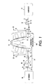
FIG. 1 is a simplified elevational view of a direct-to-web, continuous-web, phase-change ink printer. -
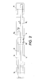
FIG. 2 is bottom view of the direct-to-web, continuous-web, phase-change ink printer ofFIG. 1 . -
FIG. 3 is a plan view of an embodiment of an inversion system for use with the imaging device ofFIG. 1 . - For a general understanding of the present embodiments, reference is made to the drawings. In the drawings, like reference numerals have been used throughout to designate like elements.
- As used herein, the term "imaging device" generally refers to a device for applying an image to print media. "Print media" can be a physical sheet of paper, plastic, or other suitable physical media or substrate for images, whether precut or web fed. The imaging device may include a variety of other components, such as finishers, paper feeders, and the like, and may be embodied as a copier, printer, or a multifunction machine. A "print job" or "document" is normally a set of related sheets, usually one or more collated copy sets copied from a set of original print job sheets or electronic document page images, from a particular user, or otherwise related. An image generally may include information in electronic form which is to be rendered on the print media by the marking engine and may include text, graphics, pictures, and the like.
-
FIG. 1 is a simplified elevational view of a continuous-web printer. A web supply and transport system is configured to supply a very long (i.e., substantially continuous) web W of "substrate" (paper, plastic, or other printable material) from anunwinder 10. The web W may be unwound as needed, and propelled by a variety of motors, not shown, along a web path. A set ofrollers 12 controls the tension of the web as the web moves through the path. - As explained below, the imaging device of
FIG. 1 is a duplex printer meaning that it is capable of printing images onto both sides of the continuous web. In the embodiment ofFIG. 1 , to enable duplex printing, the web transport system (and printing system as explained below) is a dual width, or dual path, transport system that is configured to transport two lengths of the web, WS and WD, along the web path simultaneously. Accordingly, in one embodiment, the rollers that transport and guide the web along the web path are at least twice the width of the web to accommodate the two lengths of the web. As depicted inFIGS. 1 and2 , afirst side 14 of the web transport system is configured to transport a portion of the web WS with one of the surfaces, i.e.,simplex surface 16, of the web facing in a direction to be printed upon by the printheads of the print station, also referred to herein as the printing direction. Thesecond side 18 of the web transport system is configured to transport a portion of the web with the opposite surface, i.e., theduplex surface 20, of the web facing the printing direction. For the purposes of this disclosure, the first orsimplex side 14 and the second orduplex side 18 of the web transport system may also be referred to as he first or simplex web path and the second or duplex web path, respectively. The dual web path of the web transport system includes entrance roller(s) 26 and an exit roller(s) 28. - The web transport system is configured to transport the web along the simplex 14 and
duplex 18 web paths simultaneously and maintain consistent lateral positioning of the webs at least in the print zone so that images formed on the web are accurately registered. Any suitable method of registering or positioning of the webs along the dual path web transport system may be utilized. For example, edge sensors, as are known in the art, may be used to detect the edges of the webs, and suitable mechanisms for correcting or compensating for deviations of the web positions from desired positions may be used to adjust the lateral positions of the web at one or more positions along the dual web paths to ensure consistent and accurate positioning and/or spacing of the webs at least in the print zone. - As depicted in
FIGS. 1 and2 , thesimplex web 14 path of the dual path web transport system is configured to receive the continuous web from theunwinder 10 with thesimplex surface 16 of the web facing in the printing direction. Theduplex web path 18 of the web transport system is configured to receive the continuous web from areturn path 24 that directs the continuous web moving on thesimplex web path 14 from theexit 28 located after the printing system back to theentrance 12 of the duplex web path. As explained below, aninversion system 100 is positioned on the return path that is configured to invert the continuous web so that the surface opposite the simplex surface of the web (i.e., the duplex surface) is facing in the printing direction when it enters the duplex web path at the entrance to the web transport system. In addition, the inversion system is configured to automatically laterally register the web so that it accurately enters the duplex web path. - Although not depicted in to
FIG. 1 , along the dual paths of the web transport system there may be provided a preheater , which brings the webs to an initial predetermined temperature. The preheater can rely on contact, radiant, conductive, or convective heat to bring the web W to a target preheat temperature, which in one practical embodiment, is in a range of about 30°C to about 70°C. - The simplex and duplex web paths guide the respective webs W through a printing station or system including a series of
printheads 22, each printhead effectively extending across the dual width of the web paths. In the embodiment ofFIG. 1 , the imaging device is a direct marking device in which the printheads are configured to place marking material directly (i.e., without use of an intermediate or offset member) onto the surfaces of the webs that are facing in the printing direction, e.g., the simplex surface of the web moving along the simplex web path and/or the duplex surface of the web moving along the duplex web path. In alternative embodiments, however, the imaging device may be configured as an indirect marking imaging device as known in the art. As is generally familiar, each of the four primary-color images placed on overlapping areas on a web combine to form a full-color image, based on the image data sent to each printhead. In various possible embodiments, there may be providedmultiple printheads 22 for each primary color; the printheads can each be formed into a single linear array; the function of each color printhead can be divided among multiple distinct printheads located at different locations along the process direction; or the printheads or portions thereof can be mounted movably in a direction CP transverse to the process direction P, such as for spot-color applications. - In one embodiment, the marking material comprises a "phase-change ink," by which is meant that the ink is substantially solid at room temperature and substantially liquid when initially jetted onto the web W. Currently, common phase change inks are typically heated to about 100°C to 140°C to melt the solid ink for jetting onto the web W. Generally speaking, the liquid ink cools down quickly upon hitting the web W. Alternatively, however, the marking material may be any suitable type of marking material, such as aqueous ink, wax-based ink, toner, UV curable ink, and the like.
- Associated with each
printhead 22 is a backingmember 26, typically in the form of a bar or roll, which is arranged substantially opposite the printhead on the other side of web W. Each backing member is used to position the web W so that the gap between the printhead and the web stays at a known, constant distance. Each backing member can be controlled to cause the adjacent portion of the web to reach a predetermined "ink-receiving" temperature, in one practical embodiment, of about 40°C to about 60°C. In various possible embodiments, each backing member can include heating elements, cavities for the flow of liquids therethrough, etc.; alternatively, the "member" can be in the form of a flow of air or other gas against or near a portion of the web W. The combined actions of the preheater plusbacking members 26 held to a particular target temperature effectively maintains the web W in the printing zone in a predetermined temperature range of about 40°C to 70°C. - Following the printing zone along the dual web path W is one or more "midheaters" 30.
Midheaters 30 can use contact, radiant, conductive, and/or convective heat to bring the web W to the target temperature. Themidheaters 30 bring the ink placed on the web to a temperature suitable for desired properties when the ink on the web is sent through thespreader 40. In one embodiment, a useful range for a target temperature for the midheater is about 35°C to about 80°C. The midheaters 30 have the effect of equalizing the ink and substrate temperatures to within about 15°C of each other. Lower ink temperature gives less line spread while higher ink temperature causes show-through (visibility of the image from the other side of the print). Themidheaters 30 adjust substrate and ink temperatures to 0°C to 20°C above the temperature of the spreader, which will be described below. - Following the
midheaters 30, along the dual path of web W, is a "spreader" 40, that applies a predetermined pressure, and in some implementations, heat, to the web W. The function of thespreader 40 is to take what are essentially isolated droplets of ink on web W and smear them out to make a continuous layer by pressure, and, in one embodiment, heat, so that spaces between adjacent drops are filled and image solids become uniform. In addition to spreading the ink, thespreader 40 may also improve image permanence by increasing ink layer cohesion and/or increasing the ink-web adhesion. Thespreader 40 includes rolls, such as image-side roll 42 andpressure roll 44, that apply heat and pressure to the web W. Either roll can include heat elements to bring the web W to a temperature in a range from about 35°C to about 80°C. - In one practical embodiment, the roll temperature in
spreader 40 is maintained at about 55°C; generally, a lower roll temperature gives less line spread while a higher temperature causes imperfections in the gloss. A roll temperature higher than about 57°C causes ink to offset to the roll. In one practical embodiment, the nip pressure is set in a range of about 500 to about 2000 psi lbs/side. Lower nip pressure gives less line spread while higher may reduce pressure roll life. - The
spreader 40 can also include a cleaning/oiling station 48 associated with image-side roll 42, suitable for cleaning and/or applying a layer of some lubricant or other material to the roll surface. Such a station coats the surface of the spreader roll with a lubricant such as amino silicone oil having viscosity of about 10-200 centipoises. Only small amounts of oil are required and the oil carry out by web W is only about 1-10 mg per A4 size page. In one possible embodiment, themidheater 30 andspreader 40 can be combined within a single unit, with their respective functions occurring relative to the same portion of web W simultaneously. - Following passage through the
spreader 40, the web being moved along thesimplex web path 14 is directed atexit 28 onto thereturn path 24 to theinversion system 100 where the web is inverted and laterally registered for entrance onto theduplex web path 18. Following the spreader, theduplex web path 18 directs the printed web to awinder 50 which winds the web. Alternatively, the web may be directed to any of a number of other suitable finishing devices, such as cutters for cutting the web into sheets, and binders for binding the cut sheets. - As mentioned, one difficulty faced in duplex printing on a continuous web printer that utilizes a dual web path, such as described above, is consistent and lateral (cross process direction) web registration. Any registration variation occurring to the simplex web results in a cumulative error for duplex side registration. For example, a challenge for imaging devices such as described above is that drive rolls form a nip (to generate web drive and tension) that constrains the duplex or mobius loop of web to a fixed length. Any lateral registration correction of the web while printing is likely to alter the desired web path through the return path and inversion system, thereby altering affecting the path length and web tension (that could cause slack or broken web).
- Some previously known systems utilized fixed turn bars that invert the web after printing one side (e.g., simplex side), and laterally offset the web to direct the web to the entrance of the duplex web path for printing on the other side (duplex side), all without active registration. Typical setups strive to maintain alignment of the web as it enters and exits the turn bars. Making the exit turn bar adjustable may effectively change the lateral registration of the web. However, adjusting the position of the exit turn bar alters the web path length which, as mentioned above, can affect web tension to cause loss of web control, web damage, or breakage. In other previously known systems, a bias roller with a manually adjusted edge guide has also been used to laterally register the return path web, but it is known to generate loose paper dust and fibers that may contaminate the printheads, thus reducing image quality and printhead life.
- As an alternative to using the above-described previously known inversion and registration systems or methods, the present disclosure proposes the use of an inversion/registration system that utilizes a series of turn bars that are oriented to properly invert and offset a continuous web, and makes use of a control system, sensor, motor, drives, and linear slides to provide position control of the exit turn bar (and web). A linkage and counterbalance with the upstream idler roll provides lateral position control to ensure consistent web path length and maintain web tension.
-
FIG. 3 shows an embodiment of an inversion/registration system 100 that may be utilized in the imaging device ofFIG. 1 to invert and register the web for duplex printing. As depicted inFIG. 3 , the inversion/registration system 100 includes a first 90 degree turn bar (also referred to as entrance turn bar) 54, asecond turn bar 58, and a third 90 degree turn bar (also referred to as exit turn bar) 60. Theentrance turn bar 54 is positioned to receive the continuous web W moving along thereturn path 24 in a first direction A (generally back towards theentrance 26 of the web transport system shown inFIG. 1 ) with thesimplex surface 18 of the web facing downward. Theentrance turn bar 54 is angled at 45 degrees with respect to the incoming web to direct the web in a second direction B perpendicular to the first direction A and in a plane that is substantially parallel to the plane of the web at the coming into the entrance roller. The web is inverted at this point so that the simplex surface is facing upward. Thesecond turn bar 58 is positioned to receive the continuous web W from thefirst turn bar 54 and to direct the continuous web in a third direction C opposite the second direction B and in a plane parallel to the plane of the web coming into the second turn bar. Theexit turn bar 60 is positioned to receive the continuous web from thesecond turn bar 58 with the simplex surface of the web facing downward. Theexit turn bar 60 is angled at 45 degrees with respect to the incoming web to direct the web in the first direction A toward theentrance 26 to the web transport system (FIG. 1 ). The simplex surface of the web is facing upward at this point so that when the web is fed onto the duplex web path, theduplex surface 20 is facing in the printing direction to be printed upon at the printing station. - In one embodiment, the
entrance 54 and exit turn bars 60 comprise air cushion style turn bars as are known in the art in which air is directed through the bars and through a plurality of holes along the shaft in the axial direction. Alternatively, theentrance 54 and exit turn bars 60 may comprise idler rollers. In the embodiment ofFIG. 3 , thesecond turn bar 58 comprises an idler roller although any suitable type of turn bar may be used. - During operation, with drive and spreader nips retracted, the web is threaded through the printer web path, along the return path, and through the inversion/
registration system 100. The web passes through thesystem 100 via turn bars 54, 58, 60, in that order. Once threaded, tension is applied to eliminate any slack, wrinkles, etc from the web. The web drives engage and draw tension as required by the control system and media attributes. For example, the imaging device ofFIG. 1 may use velocity control via roll encoders (not shown) and tension trim via load cells (not shown) on strategic rollers to measure web tension. - The position of the
exit turn bar 60 along the axis D controls the lateral position of the web as it is fed onto the duplex web path. To enable adjustment of the lateral position of the web exiting theexit turn bar 60, theexit turn bar 60 is supported for translation along the axis D. In the embodiment ofFIG. 3 , theentrance turn bar 54,second turn bar 58, andexit turn bar 60 are supported by aframe 52. To enable translation, theexit turn bar 60 is supported on asub-frame 62 that is translatably supported by theframe 52 for movement along the D axis. Translation may be enabled in any suitable manner. For example, thesub-frame 62 of theexit turn bar 60 may be supported by theframe 52 bylinear slides 68. Any suitable device or method, however, may be used to enable translation of the exit turn bar along the D axis. - Linear motion along the D axis may be imparted to the
sub-frame 62 andexit turn bar 60 using a driver having alinear drive shaft 80 operably coupled tomotor 84. Adjustments may be made to the position of theexit turn bar 60 using asensor 64 that is configured to detect the lateral position of the web W as it exits theexit turn bar 60. Any suitable sensor may be utilized.Sensor 64 generates output indicative of the web position that may be read or received by thecontroller 32.Controller 32 is operably coupled to themotor 84 of the driver and is configured to actuate themotor 84 to cause thelinear drive shaft 80 to move based on thesensor 64 output. Movement of thedrive shaft 80 imparts a linear motion to theexit turn bar 60 mounted to sub-frame 62 onlinear slides 68. - To enable adjustment of the lateral position of the web (e.g., lateral registration of the web) without altering the overall length of the web loop in the imaging device (which may affect web tension to cause loss of web control, web damage, or breakage), the
second turn bar 58 is supported for translation along the D axis along withexit turn bar 60. For example,second turn bar 58 may be supported on asub-frame 56 that is translatably supported by theframe 52 for movement along the D axis. Translation may be enabled in any suitable manner such as bylinear slides 68. In one embodiment,sub-frame 62 ofexit turn bar 60 andsub-frame 56 ofsecond turn bar 58 are coupled together using acable 72 that extends fromsub-frame 56 ofsecond turn bar 58 towardsub-frame 62 ofexit turn bar 60 having a pulley 70 at a distal end thereof. Alinkage cable 74 is anchored to the exitturn bar sub-frame 62 at one end and is routed through the pulley 70 with 180 degrees of wrap. The other end of thecable 74 is then attached to a surface such asinversion system frame 52. - When the exit
turn bar sub-frame 62 is moved bylinear drive 80, thecable 74 transmits a force to the secondturn bar sub-frame 56 via the pulley 70. The secondturn bar sub-frame 56 may be biased away from the exitturn bar sub-frame 62 using, for example, counterbalance extension springs 78 to draw the cable tight. In this configuration, any lateral movement of theexit turn bar 60 in either direction B or C will result in exactly half the displacement of thesecond turn bar 58. Thesecond turn bar 58 has a web wrap of 180 degrees resulting in an un-altered web path length. This novel aspect ensures that consistent web tension can be maintained during web registration and enables correction and/or compensation of any registration errors. - The
inversion system 100 described above enables adjustments of the duplex web position real time. The system may require web registration adjustment for any number of reasons. In the case of a printing system, examples of reasons for registration adjustment include: web tracking errors (due to roll wear, static, environmental conditions, paper (substrate) weight changes), web roll effects (camber, curl, edge & thickness variations), or to hide missing jet visibility (as with direct marking inkjet printing) by moving web and image panel out from under bad jets (space permitting). The inversion system also has a small design envelope, allowing inversion and active registration of web for duplex printing or finishing with a minimal footprint. In addition, the system can also compensate for web tracking errors at downstream areas where critical registration is required. For example a printer could use paper edge sensors and/or simplex side image sensors in the imaging area to ascertain web and simplex side image position, as well as to ensure that the web is not skewed or tracking relative to it's position as it exits the invention. Controls, software, and system memory can be used to learn and store optimal registration position(s) based on media type or other parameter, thereby maximizing useable output and minimizing wasted output at press startup. Additional registration sensor(s) could be mounted upstream to learn web tracking and compensate as the web reaches the exit turn bar span. This could provide improved registration by removing errors prior to the exit sensor described above, and the ability to adjust lateral web position real-time for any reason.
Claims (15)
- A web inversion system (100) for use in a continuous web imaging device, the system comprising:a first turn bar (54) positioned to be partially wrapped by a substantially continuous web (W) moving in a first direction (A) with a first surface of the continuous web (W) facing in a printing direction and to direct the continuous web (W) in a second direction (B) perpendicular to the first direction (A) with a second surface of the continuous web (W) facing in the printing direction;a second turn bar (58) positioned to be partially wrapped by the continuous web (W) directed from the first turn bar (54) and to direct the continuous web (W) in a third direction (C) opposite the second direction (B) with the first surface facing in the printing direction;a third turn bar (60) positioned to be partially wrapped by the continuous web (W) directed from the second turn bar (58) and to direct the continuous web (W) in the first direction (A) with the second surface facing the printing direction;characterized by the second and the third turn bars (58,60) each being supported for translation along an axis (D) parallel to the second and third directions (B,C) and connected to each other to maintain a predetermined distance between the second and third turn bars (58,60) when translated along the axis (D); anda driver operably coupled to at least one of the second and the third turn bars (58,60) and configured to translate the second and the third turn bars (58,60) along the axis (D).
- The system of claim 1, the first, second, and third turn bars (56,58,60) each comprising an idler roller.
- The system of claim 2, the second turn bar (58) being wrapped 180 degrees by the continuous web (W).
- The system of claim 3, further comprising:a frame supporting the first, second, and third turn bars (56,58,60), the frame including guide grooves operably coupled to the second and third turn bars (58,60) for enabling translation of the second and third turn bars (58,60).
- The system of claim 4, further comprising:a pulley (70) operably coupled to the second turn bar (58); anda linkage cable wrapped around the pulley (70) and having one end attached to the third turn bar (60) and the other end attached to the frame.
- The system of claim 5, further comprising:biasing springs operably between the frame and the second turn bar (58) for biasing the second turn bar (58) in the second direction (B).
- The system of claim 6, the driver further comprising:a drive shaft operably coupled to the third turn bar (60);a motor operably coupled to the drive shaft for linearly driving the drive shaft along the axis (D); anda controller operably coupled to the motor and the sensor (64) and configured to actuate the motor based on the signal from the sensor (64).
- A continuous web transport system for use in a continuous web imaging device comprising:a source of a substantially continuous web (W) having a first surface and a second surface opposite the first surface;a web transport system having a first and a second web path each configured to transport different portions of the continuous web (W) simultaneously side by side in a process direction from a first end to a second end of the web transport system with the different portions being coplanar and laterally spaced a predetermined distance from each other in a cross-process direction, the web transport system including a return path for directing a web portion on the first web path from the second end to the first end and onto the second web path, the first web path receiving the continuous web (W) from the source with the first surface of the continuous web (W) facing in a printing direction;an inversion system (100) positioned along the return path between the exit and the entrance, the inversion system (100) including:a first turn bar (54) positioned to receive the continuous web (W) moving in a first direction (A) toward the first end in a first plane with the first surface facing in the printing direction and to direct the continuous web (W) in a second direction (B) perpendicular to the first direction (A) in a second plane parallel to the first plane with the second surface facing in the printing direction;a second turn bar (58) positioned to receive the continuous web (W) from the first turn bar (54) and to direct the continuous web (W) in a third direction (C) opposite the second direction (B) in a third plane parallel to the first plane with the first surface facing in the printing direction;a third turn bar (60) positioned to receive the continuous web (W) from the second turn bar (58) and to direct the continuous web (W) in the first direction (A) in a fourth plane parallel to the first plane with the second surface facing the printing direction,characterized by the second and the third turn bars (58,60) each being supported for translation along an axis (D) parallel to the second and third directions (B,C) and connected to each other to maintain a predetermined distance between the second and third turn bars (58,60) along the axis (D) when translated;a sensor (64) configured to generate a signal indicative of a lateral position of the continuous web (W) exiting the third turn bar (60); anda driver operably coupled to at least one of the second and the third turn bars (58,60) and configured to adjust a position of the third turn bar (60) along the axis (D) based on the signal.
- The system of claim 8, the first, second, and third turn bars (56,58,60) each comprising an idler roller.
- The system of claim 9, the second turn bar (58) being wrapped 180 degrees by the continuous web (W).
- The system of claim 10, further comprising:a frame supporting the first, second, and third turn bars (56,58,60), the frame including guide grooves operably coupled to the second and third turn bars (58,60) for enabling translation of the second and third turn bars (58,60).
- The system of claim 11, further comprising:a pulley (70) operably coupled to the second turn bar (58); anda linkage cable wrapped around the pulley (70) and having one end attached to the third turn bar (60) and the other end attached to the frame.
- The system of claim 12, further comprising:biasing springs operably between the frame and the second turn bar (58) for biasing the second turn bar (58) in the second direction (B).
- The system of claim 13, the driver further comprising:a drive shaft operably coupled to the third turn bar (60);a motor operably coupled to the drive shaft for linearly driving the drive shaft along the axis (D); anda controller operably coupled to the motor and the sensor (64) and configured to actuate the motor based on the signal from the sensor (64).
- A continuous web imaging device comprising:a source of a substantially continuous web (W) having a first surface and a second surface opposite the first surface;a web transport system having a first and a second web path each configured to transport different portions of the continuous web (W) simultaneously side by side in a process direction from a first end to a second end of the web transport system with the different portions being coplanar and laterally spaced a predetermined distance from each other in a cross-process direction, the web transport system including a return path for directing a web portion on the first web path from the second end to the first end and onto the second web path, the first web path receiving the continuous web (W) from the source with the first surface of the continuous web (W) facing in a printing direction;a printing system located along the first and the second web paths and configured to deposit marking material onto surfaces of the continuous web (W) moving along the first and the second web paths that are facing the printing direction;an inversion system (100) positioned along the return path between the exit and the entrance, the inversion system (100) including:a first turn bar (54) positioned to receive the continuous web (W) moving in a first direction (A) toward the first end in a first plane with the first surface facing in the printing direction and to direct the continuous web (W) in a second direction (B) perpendicular to the first direction (A) in a second plane parallel to the first plane with the second surface facing in the printing direction;a second turn bar (58) positioned to receive the continuous web (W) from the first turn bar (54) and to direct the continuous web (W) in a third direction (C) opposite the second direction (B) in a third plane parallel to the first plane with the first surface facing in the printing direction;a third turn bar (60) positioned to receive the continuous web (W) from the second turn bar (58) and to direct the continuous web (W) in the first direction (A) in a fourth plane parallel to the first plane with the second surface facing the printing direction, the second web path being configured to receive the continuous web (W) from the third turn bar (60) with the second surface facing the printing direction;characterized by the second and the third turn bars (58,60) each being supported for translation along an axis (D) parallel to the second and third directions (B,C) and connected to each other to maintain a predetermined distance between the second and third turn bars (58,60) along the axis (D) when translated;a sensor (64) configured to generate a signal indicative of a lateral position of the continuous web (W) exiting the third turn bar (60); anda driver operably coupled to at least one of the second and the third turn bars (58,60) and configured to adjust a position of the third turn bar (60) along the axis (D) based on the signal.
Applications Claiming Priority (1)
| Application Number | Priority Date | Filing Date | Title |
|---|---|---|---|
| US12/560,483 US8316766B2 (en) | 2009-09-16 | 2009-09-16 | Media inversion system for a continuous web printer |
Publications (3)
| Publication Number | Publication Date |
|---|---|
| EP2338816A2 EP2338816A2 (en) | 2011-06-29 |
| EP2338816A3 EP2338816A3 (en) | 2011-09-28 |
| EP2338816B1 true EP2338816B1 (en) | 2013-08-28 |
Family
ID=43304769
Family Applications (1)
| Application Number | Title | Priority Date | Filing Date |
|---|---|---|---|
| EP10177062.6A Not-in-force EP2338816B1 (en) | 2009-09-16 | 2010-09-16 | Media inversion system for a continuous web printer |
Country Status (5)
| Country | Link |
|---|---|
| US (2) | US8316766B2 (en) |
| EP (1) | EP2338816B1 (en) |
| JP (1) | JP5406808B2 (en) |
| KR (1) | KR101573944B1 (en) |
| CN (1) | CN102029809B (en) |
Families Citing this family (12)
| Publication number | Priority date | Publication date | Assignee | Title |
|---|---|---|---|---|
| JP5043980B2 (en) * | 2010-04-22 | 2012-10-10 | キヤノン株式会社 | Printing device |
| DE202011106176U1 (en) * | 2011-09-29 | 2011-11-16 | Bikoma Ag Spezialmaschinen | Turning device for a material web processing machine |
| US8740061B2 (en) * | 2012-07-06 | 2014-06-03 | Hewlett-Packard Development Company, L.P. | Recording information for a web manufacturing process |
| US9010924B2 (en) | 2012-07-11 | 2015-04-21 | Xerox Corporation | System and method for aligning duplex images using alignment marks |
| CN103009785A (en) * | 2012-09-18 | 2013-04-03 | 苏州市三峰印刷机械有限公司 | Paper strip turning device for rotary press |
| US8777399B2 (en) | 2012-09-26 | 2014-07-15 | Xerox Corporation | System and method for first and second side process registration in a single print zone duplex web printer |
| JP6258972B2 (en) * | 2013-01-14 | 2018-01-10 | マイクログリーン ポリマーズ,インク. | System for unwinding a roll of thermoplastic material interleaved with a porous material and associated method |
| DE102013107451A1 (en) * | 2013-07-15 | 2015-01-15 | Océ Printing Systems GmbH & Co. KG | Printing device for double-sided printing of a strip-shaped substrate |
| WO2015065446A1 (en) * | 2013-10-31 | 2015-05-07 | Hewlett-Packard Development Company, L.P. | Printing on a media web |
| KR101757823B1 (en) * | 2014-06-20 | 2017-07-14 | 킴벌리-클라크 월드와이드, 인크. | Apparatus and method for controlling the unwinding of a web |
| US11945207B2 (en) * | 2018-10-29 | 2024-04-02 | Hewlett-Packard Development Company, L.P. | Web shift compensation |
| WO2022271158A1 (en) * | 2021-06-22 | 2022-12-29 | Hewlett-Packard Development Company, L.P. | Printing to substrates |
Family Cites Families (22)
| Publication number | Priority date | Publication date | Assignee | Title |
|---|---|---|---|---|
| US3598332A (en) * | 1969-02-05 | 1971-08-10 | Melvin Sharkey | Web-supporting roller assembly |
| DD234644A1 (en) | 1985-02-14 | 1986-04-09 | Polygraph Leipzig | DEVICE FOR REGULATING THE RAILWAY LOCATION |
| US4778093A (en) * | 1987-04-13 | 1988-10-18 | Walter Renold | Film transport assembly |
| DE3816900C1 (en) * | 1988-05-18 | 1989-11-16 | Man Roland Druckmaschinen Ag, 6050 Offenbach, De | |
| DE4013229C1 (en) * | 1990-04-26 | 1991-11-07 | Man Roland Druckmaschinen Ag, 6050 Offenbach, De | |
| US5016801A (en) * | 1990-08-28 | 1991-05-21 | Industrial Label Corporation | Multiple-ply web registration apparatus |
| EP0582927B1 (en) * | 1992-08-10 | 1997-11-19 | KOENIG & BAUER-ALBERT AKTIENGESELLSCHAFT | Turning bar for web material |
| DE59400220D1 (en) * | 1994-08-19 | 1996-05-23 | Siemens Nixdorf Inf Syst | Turning device for tape-shaped recording media |
| US5970304A (en) * | 1997-09-30 | 1999-10-19 | Xerox Corporation | Two sided imaging of a continuous web substrate with a single print engine with in line transfer stations |
| US6050191A (en) * | 1997-10-16 | 2000-04-18 | Scitex Digital Printing, Inc. | System and method for providing multi-pass imaging in a printing system |
| DE19751417C1 (en) | 1997-11-14 | 1999-06-24 | Ifs Systembau Ingenieurgesells | Textile web feed guide |
| US6487388B2 (en) * | 2001-01-24 | 2002-11-26 | Xerox Corporation | System and method for duplex printing |
| US6666399B2 (en) * | 2001-06-18 | 2003-12-23 | Xerox Corporation | System for transfer and inversion of a continuous web substrate between printing and other devices |
| JP3944834B2 (en) * | 2002-03-08 | 2007-07-18 | 株式会社ミヤコシ | Printing device |
| JP4385222B2 (en) | 2004-05-07 | 2009-12-16 | 株式会社ミヤコシ | Paper threading device |
| JP4485923B2 (en) * | 2004-11-19 | 2010-06-23 | 大日本スクリーン製造株式会社 | Duplex printing device |
| JP2006219226A (en) | 2005-02-08 | 2006-08-24 | Fuji Xerox Co Ltd | Turn bar device |
| JP2007050955A (en) * | 2005-08-17 | 2007-03-01 | Hitachi Maxell Ltd | Web turn device |
| JP5285207B2 (en) | 2006-01-26 | 2013-09-11 | 株式会社ミヤコシ | Printing device |
| JP4304530B2 (en) * | 2006-03-23 | 2009-07-29 | セイコーエプソン株式会社 | Conveyance path switching device in double-sided recording device, double-sided recording device provided with the same |
| JP4306743B2 (en) * | 2007-02-28 | 2009-08-05 | ブラザー工業株式会社 | Image recording device |
| JP2008265918A (en) * | 2007-04-18 | 2008-11-06 | Tokyo Kikai Seisakusho Ltd | Turn bar device for rotary press |
-
2009
- 2009-09-16 US US12/560,483 patent/US8316766B2/en active Active
-
2010
- 2010-09-14 KR KR1020100089964A patent/KR101573944B1/en not_active IP Right Cessation
- 2010-09-14 JP JP2010205404A patent/JP5406808B2/en not_active Expired - Fee Related
- 2010-09-16 CN CN201010290842.7A patent/CN102029809B/en not_active Expired - Fee Related
- 2010-09-16 EP EP10177062.6A patent/EP2338816B1/en not_active Not-in-force
-
2012
- 2012-09-11 US US13/610,353 patent/US8646385B2/en active Active
Also Published As
| Publication number | Publication date |
|---|---|
| US20130002779A1 (en) | 2013-01-03 |
| CN102029809A (en) | 2011-04-27 |
| EP2338816A2 (en) | 2011-06-29 |
| US8316766B2 (en) | 2012-11-27 |
| JP5406808B2 (en) | 2014-02-05 |
| KR20110030358A (en) | 2011-03-23 |
| CN102029809B (en) | 2014-10-29 |
| US20110064507A1 (en) | 2011-03-17 |
| EP2338816A3 (en) | 2011-09-28 |
| US8646385B2 (en) | 2014-02-11 |
| JP2011063443A (en) | 2011-03-31 |
| KR101573944B1 (en) | 2015-12-02 |
Similar Documents
| Publication | Publication Date | Title |
|---|---|---|
| EP2338816B1 (en) | Media inversion system for a continuous web printer | |
| US7828423B2 (en) | Ink-jet printer using phase-change ink printing on a continuous web | |
| US8350879B2 (en) | Non-contact heating of solid ink prints after ink fixing | |
| US8152288B2 (en) | Method and system for achieving uniform ink and web temperatures for spreading | |
| US8262186B2 (en) | Pre-leveler cooling device for continuous feed imaging devices | |
| US20110063359A1 (en) | Real Time Bleed-Though Detection for Continuous Web Printers | |
| US8714729B2 (en) | Modular roll bar assembly with temperature control system for heating or cooling web | |
| US8162469B2 (en) | Method for achieving uniform media temperature and size throughout the pre-heat zone | |
| US9079426B2 (en) | Duplexing web press with drying time control | |
| US9682573B2 (en) | Printer having edge control apparatus for web media | |
| US20130101331A1 (en) | Web press and a method of initiating printing | |
| US10377128B2 (en) | Method for controlling a web in a printing apparatus | |
| US20130104760A1 (en) | Web press and a method of duplex printing | |
| US20140125730A1 (en) | Method for Printing Phase Change Ink onto Porous Media | |
| EP3301047B1 (en) | A web transport assembly for transporting a web along a processing unit | |
| US20130286072A1 (en) | Correcting web skew in a printing system | |
| JP2000025214A (en) | Left/right print synchronism shift detector for ink jet printer | |
| EP1574348B1 (en) | Tensioning system for printing devices | |
| US20150231900A1 (en) | Method for forming an inkjet image | |
| WO2011162763A1 (en) | Web press and a method of printing |
Legal Events
| Date | Code | Title | Description |
|---|---|---|---|
| PUAI | Public reference made under article 153(3) epc to a published international application that has entered the european phase |
Free format text: ORIGINAL CODE: 0009012 |
|
| AK | Designated contracting states |
Kind code of ref document: A2 Designated state(s): AL AT BE BG CH CY CZ DE DK EE ES FI FR GB GR HR HU IE IS IT LI LT LU LV MC MK MT NL NO PL PT RO SE SI SK SM TR |
|
| AX | Request for extension of the european patent |
Extension state: BA ME RS |
|
| PUAL | Search report despatched |
Free format text: ORIGINAL CODE: 0009013 |
|
| AK | Designated contracting states |
Kind code of ref document: A3 Designated state(s): AL AT BE BG CH CY CZ DE DK EE ES FI FR GB GR HR HU IE IS IT LI LT LU LV MC MK MT NL NO PL PT RO SE SI SK SM TR |
|
| AX | Request for extension of the european patent |
Extension state: BA ME RS |
|
| RIC1 | Information provided on ipc code assigned before grant |
Ipc: B65H 23/188 20060101ALI20110822BHEP Ipc: B65H 23/32 20060101ALI20110822BHEP Ipc: B41J 15/16 20060101AFI20110822BHEP Ipc: B65H 23/035 20060101ALI20110822BHEP |
|
| 17P | Request for examination filed |
Effective date: 20120328 |
|
| REG | Reference to a national code |
Ref country code: DE Ref legal event code: R079 Ref document number: 602010009737 Country of ref document: DE Free format text: PREVIOUS MAIN CLASS: B65H0023320000 Ipc: B41J0015160000 |
|
| RIC1 | Information provided on ipc code assigned before grant |
Ipc: B65H 23/188 20060101ALI20121207BHEP Ipc: B41J 15/16 20060101AFI20121207BHEP Ipc: B65H 23/035 20060101ALI20121207BHEP Ipc: B65H 23/32 20060101ALI20121207BHEP |
|
| GRAP | Despatch of communication of intention to grant a patent |
Free format text: ORIGINAL CODE: EPIDOSNIGR1 |
|
| INTG | Intention to grant announced |
Effective date: 20130514 |
|
| GRAS | Grant fee paid |
Free format text: ORIGINAL CODE: EPIDOSNIGR3 |
|
| GRAA | (expected) grant |
Free format text: ORIGINAL CODE: 0009210 |
|
| AK | Designated contracting states |
Kind code of ref document: B1 Designated state(s): AL AT BE BG CH CY CZ DE DK EE ES FI FR GB GR HR HU IE IS IT LI LT LU LV MC MK MT NL NO PL PT RO SE SI SK SM TR |
|
| REG | Reference to a national code |
Ref country code: GB Ref legal event code: FG4D |
|
| REG | Reference to a national code |
Ref country code: CH Ref legal event code: EP |
|
| REG | Reference to a national code |
Ref country code: AT Ref legal event code: REF Ref document number: 629086 Country of ref document: AT Kind code of ref document: T Effective date: 20130915 |
|
| REG | Reference to a national code |
Ref country code: IE Ref legal event code: FG4D |
|
| REG | Reference to a national code |
Ref country code: DE Ref legal event code: R096 Ref document number: 602010009737 Country of ref document: DE Effective date: 20131024 |
|
| REG | Reference to a national code |
Ref country code: AT Ref legal event code: MK05 Ref document number: 629086 Country of ref document: AT Kind code of ref document: T Effective date: 20130828 |
|
| REG | Reference to a national code |
Ref country code: LT Ref legal event code: MG4D |
|
| REG | Reference to a national code |
Ref country code: NL Ref legal event code: VDEP Effective date: 20130828 |
|
| PG25 | Lapsed in a contracting state [announced via postgrant information from national office to epo] |
Ref country code: CY Free format text: LAPSE BECAUSE OF FAILURE TO SUBMIT A TRANSLATION OF THE DESCRIPTION OR TO PAY THE FEE WITHIN THE PRESCRIBED TIME-LIMIT Effective date: 20130724 Ref country code: NO Free format text: LAPSE BECAUSE OF FAILURE TO SUBMIT A TRANSLATION OF THE DESCRIPTION OR TO PAY THE FEE WITHIN THE PRESCRIBED TIME-LIMIT Effective date: 20131128 Ref country code: HR Free format text: LAPSE BECAUSE OF FAILURE TO SUBMIT A TRANSLATION OF THE DESCRIPTION OR TO PAY THE FEE WITHIN THE PRESCRIBED TIME-LIMIT Effective date: 20130828 Ref country code: SE Free format text: LAPSE BECAUSE OF FAILURE TO SUBMIT A TRANSLATION OF THE DESCRIPTION OR TO PAY THE FEE WITHIN THE PRESCRIBED TIME-LIMIT Effective date: 20130828 Ref country code: IS Free format text: LAPSE BECAUSE OF FAILURE TO SUBMIT A TRANSLATION OF THE DESCRIPTION OR TO PAY THE FEE WITHIN THE PRESCRIBED TIME-LIMIT Effective date: 20131228 Ref country code: LT Free format text: LAPSE BECAUSE OF FAILURE TO SUBMIT A TRANSLATION OF THE DESCRIPTION OR TO PAY THE FEE WITHIN THE PRESCRIBED TIME-LIMIT Effective date: 20130828 Ref country code: PT Free format text: LAPSE BECAUSE OF FAILURE TO SUBMIT A TRANSLATION OF THE DESCRIPTION OR TO PAY THE FEE WITHIN THE PRESCRIBED TIME-LIMIT Effective date: 20131230 Ref country code: AT Free format text: LAPSE BECAUSE OF FAILURE TO SUBMIT A TRANSLATION OF THE DESCRIPTION OR TO PAY THE FEE WITHIN THE PRESCRIBED TIME-LIMIT Effective date: 20130828 |
|
| REG | Reference to a national code |
Ref country code: NL Ref legal event code: VDEP Effective date: 20130828 |
|
| PG25 | Lapsed in a contracting state [announced via postgrant information from national office to epo] |
Ref country code: GR Free format text: LAPSE BECAUSE OF FAILURE TO SUBMIT A TRANSLATION OF THE DESCRIPTION OR TO PAY THE FEE WITHIN THE PRESCRIBED TIME-LIMIT Effective date: 20131129 Ref country code: FI Free format text: LAPSE BECAUSE OF FAILURE TO SUBMIT A TRANSLATION OF THE DESCRIPTION OR TO PAY THE FEE WITHIN THE PRESCRIBED TIME-LIMIT Effective date: 20130828 Ref country code: PL Free format text: LAPSE BECAUSE OF FAILURE TO SUBMIT A TRANSLATION OF THE DESCRIPTION OR TO PAY THE FEE WITHIN THE PRESCRIBED TIME-LIMIT Effective date: 20130828 Ref country code: BE Free format text: LAPSE BECAUSE OF FAILURE TO SUBMIT A TRANSLATION OF THE DESCRIPTION OR TO PAY THE FEE WITHIN THE PRESCRIBED TIME-LIMIT Effective date: 20130828 Ref country code: SI Free format text: LAPSE BECAUSE OF FAILURE TO SUBMIT A TRANSLATION OF THE DESCRIPTION OR TO PAY THE FEE WITHIN THE PRESCRIBED TIME-LIMIT Effective date: 20130828 Ref country code: LV Free format text: LAPSE BECAUSE OF FAILURE TO SUBMIT A TRANSLATION OF THE DESCRIPTION OR TO PAY THE FEE WITHIN THE PRESCRIBED TIME-LIMIT Effective date: 20130828 |
|
| PG25 | Lapsed in a contracting state [announced via postgrant information from national office to epo] |
Ref country code: CY Free format text: LAPSE BECAUSE OF FAILURE TO SUBMIT A TRANSLATION OF THE DESCRIPTION OR TO PAY THE FEE WITHIN THE PRESCRIBED TIME-LIMIT Effective date: 20130828 |
|
| PG25 | Lapsed in a contracting state [announced via postgrant information from national office to epo] |
Ref country code: RO Free format text: LAPSE BECAUSE OF FAILURE TO SUBMIT A TRANSLATION OF THE DESCRIPTION OR TO PAY THE FEE WITHIN THE PRESCRIBED TIME-LIMIT Effective date: 20130828 Ref country code: EE Free format text: LAPSE BECAUSE OF FAILURE TO SUBMIT A TRANSLATION OF THE DESCRIPTION OR TO PAY THE FEE WITHIN THE PRESCRIBED TIME-LIMIT Effective date: 20130828 Ref country code: NL Free format text: LAPSE BECAUSE OF FAILURE TO SUBMIT A TRANSLATION OF THE DESCRIPTION OR TO PAY THE FEE WITHIN THE PRESCRIBED TIME-LIMIT Effective date: 20130828 Ref country code: DK Free format text: LAPSE BECAUSE OF FAILURE TO SUBMIT A TRANSLATION OF THE DESCRIPTION OR TO PAY THE FEE WITHIN THE PRESCRIBED TIME-LIMIT Effective date: 20130828 Ref country code: SK Free format text: LAPSE BECAUSE OF FAILURE TO SUBMIT A TRANSLATION OF THE DESCRIPTION OR TO PAY THE FEE WITHIN THE PRESCRIBED TIME-LIMIT Effective date: 20130828 Ref country code: CZ Free format text: LAPSE BECAUSE OF FAILURE TO SUBMIT A TRANSLATION OF THE DESCRIPTION OR TO PAY THE FEE WITHIN THE PRESCRIBED TIME-LIMIT Effective date: 20130828 |
|
| PG25 | Lapsed in a contracting state [announced via postgrant information from national office to epo] |
Ref country code: IT Free format text: LAPSE BECAUSE OF FAILURE TO SUBMIT A TRANSLATION OF THE DESCRIPTION OR TO PAY THE FEE WITHIN THE PRESCRIBED TIME-LIMIT Effective date: 20130828 Ref country code: MC Free format text: LAPSE BECAUSE OF FAILURE TO SUBMIT A TRANSLATION OF THE DESCRIPTION OR TO PAY THE FEE WITHIN THE PRESCRIBED TIME-LIMIT Effective date: 20130828 Ref country code: ES Free format text: LAPSE BECAUSE OF FAILURE TO SUBMIT A TRANSLATION OF THE DESCRIPTION OR TO PAY THE FEE WITHIN THE PRESCRIBED TIME-LIMIT Effective date: 20130828 |
|
| REG | Reference to a national code |
Ref country code: DE Ref legal event code: R097 Ref document number: 602010009737 Country of ref document: DE |
|
| REG | Reference to a national code |
Ref country code: IE Ref legal event code: MM4A |
|
| PLBE | No opposition filed within time limit |
Free format text: ORIGINAL CODE: 0009261 |
|
| STAA | Information on the status of an ep patent application or granted ep patent |
Free format text: STATUS: NO OPPOSITION FILED WITHIN TIME LIMIT |
|
| PG25 | Lapsed in a contracting state [announced via postgrant information from national office to epo] |
Ref country code: IE Free format text: LAPSE BECAUSE OF NON-PAYMENT OF DUE FEES Effective date: 20130916 |
|
| 26N | No opposition filed |
Effective date: 20140530 |
|
| REG | Reference to a national code |
Ref country code: DE Ref legal event code: R097 Ref document number: 602010009737 Country of ref document: DE Effective date: 20140530 |
|
| REG | Reference to a national code |
Ref country code: CH Ref legal event code: PL |
|
| PG25 | Lapsed in a contracting state [announced via postgrant information from national office to epo] |
Ref country code: SM Free format text: LAPSE BECAUSE OF FAILURE TO SUBMIT A TRANSLATION OF THE DESCRIPTION OR TO PAY THE FEE WITHIN THE PRESCRIBED TIME-LIMIT Effective date: 20130828 |
|
| PG25 | Lapsed in a contracting state [announced via postgrant information from national office to epo] |
Ref country code: TR Free format text: LAPSE BECAUSE OF FAILURE TO SUBMIT A TRANSLATION OF THE DESCRIPTION OR TO PAY THE FEE WITHIN THE PRESCRIBED TIME-LIMIT Effective date: 20130828 Ref country code: MT Free format text: LAPSE BECAUSE OF FAILURE TO SUBMIT A TRANSLATION OF THE DESCRIPTION OR TO PAY THE FEE WITHIN THE PRESCRIBED TIME-LIMIT Effective date: 20130828 |
|
| PG25 | Lapsed in a contracting state [announced via postgrant information from national office to epo] |
Ref country code: BG Free format text: LAPSE BECAUSE OF FAILURE TO SUBMIT A TRANSLATION OF THE DESCRIPTION OR TO PAY THE FEE WITHIN THE PRESCRIBED TIME-LIMIT Effective date: 20130828 Ref country code: MK Free format text: LAPSE BECAUSE OF FAILURE TO SUBMIT A TRANSLATION OF THE DESCRIPTION OR TO PAY THE FEE WITHIN THE PRESCRIBED TIME-LIMIT Effective date: 20130828 Ref country code: HU Free format text: LAPSE BECAUSE OF FAILURE TO SUBMIT A TRANSLATION OF THE DESCRIPTION OR TO PAY THE FEE WITHIN THE PRESCRIBED TIME-LIMIT; INVALID AB INITIO Effective date: 20100916 Ref country code: CH Free format text: LAPSE BECAUSE OF NON-PAYMENT OF DUE FEES Effective date: 20140930 Ref country code: LU Free format text: LAPSE BECAUSE OF NON-PAYMENT OF DUE FEES Effective date: 20130916 Ref country code: LI Free format text: LAPSE BECAUSE OF NON-PAYMENT OF DUE FEES Effective date: 20140930 |
|
| REG | Reference to a national code |
Ref country code: FR Ref legal event code: PLFP Year of fee payment: 7 |
|
| REG | Reference to a national code |
Ref country code: FR Ref legal event code: PLFP Year of fee payment: 8 |
|
| REG | Reference to a national code |
Ref country code: FR Ref legal event code: PLFP Year of fee payment: 9 |
|
| PG25 | Lapsed in a contracting state [announced via postgrant information from national office to epo] |
Ref country code: AL Free format text: LAPSE BECAUSE OF FAILURE TO SUBMIT A TRANSLATION OF THE DESCRIPTION OR TO PAY THE FEE WITHIN THE PRESCRIBED TIME-LIMIT Effective date: 20130828 |
|
| PGFP | Annual fee paid to national office [announced via postgrant information from national office to epo] |
Ref country code: DE Payment date: 20180821 Year of fee payment: 9 Ref country code: FR Payment date: 20180822 Year of fee payment: 9 |
|
| PGFP | Annual fee paid to national office [announced via postgrant information from national office to epo] |
Ref country code: GB Payment date: 20180823 Year of fee payment: 9 |
|
| REG | Reference to a national code |
Ref country code: DE Ref legal event code: R119 Ref document number: 602010009737 Country of ref document: DE |
|
| PG25 | Lapsed in a contracting state [announced via postgrant information from national office to epo] |
Ref country code: DE Free format text: LAPSE BECAUSE OF NON-PAYMENT OF DUE FEES Effective date: 20200401 |
|
| GBPC | Gb: european patent ceased through non-payment of renewal fee |
Effective date: 20190916 |
|
| PG25 | Lapsed in a contracting state [announced via postgrant information from national office to epo] |
Ref country code: FR Free format text: LAPSE BECAUSE OF NON-PAYMENT OF DUE FEES Effective date: 20190930 Ref country code: GB Free format text: LAPSE BECAUSE OF NON-PAYMENT OF DUE FEES Effective date: 20190916 |