EP2338803A1 - A collapsible container - Google Patents
A collapsible container Download PDFInfo
- Publication number
- EP2338803A1 EP2338803A1 EP10171140A EP10171140A EP2338803A1 EP 2338803 A1 EP2338803 A1 EP 2338803A1 EP 10171140 A EP10171140 A EP 10171140A EP 10171140 A EP10171140 A EP 10171140A EP 2338803 A1 EP2338803 A1 EP 2338803A1
- Authority
- EP
- European Patent Office
- Prior art keywords
- container
- end wall
- latching
- actuator
- latching member
- Prior art date
- Legal status (The legal status is an assumption and is not a legal conclusion. Google has not performed a legal analysis and makes no representation as to the accuracy of the status listed.)
- Granted
Links
Images


Classifications
-
- B—PERFORMING OPERATIONS; TRANSPORTING
- B65—CONVEYING; PACKING; STORING; HANDLING THIN OR FILAMENTARY MATERIAL
- B65D—CONTAINERS FOR STORAGE OR TRANSPORT OF ARTICLES OR MATERIALS, e.g. BAGS, BARRELS, BOTTLES, BOXES, CANS, CARTONS, CRATES, DRUMS, JARS, TANKS, HOPPERS, FORWARDING CONTAINERS; ACCESSORIES, CLOSURES, OR FITTINGS THEREFOR; PACKAGING ELEMENTS; PACKAGES
- B65D11/00—Containers having bodies formed by interconnecting or uniting two or more rigid, or substantially rigid, components made wholly or mainly of plastics material
- B65D11/18—Containers having bodies formed by interconnecting or uniting two or more rigid, or substantially rigid, components made wholly or mainly of plastics material collapsible, i.e. with walls hinged together or detachably connected
- B65D11/1833—Containers having bodies formed by interconnecting or uniting two or more rigid, or substantially rigid, components made wholly or mainly of plastics material collapsible, i.e. with walls hinged together or detachably connected whereby all side walls are hingedly connected to the base panel
-
- B—PERFORMING OPERATIONS; TRANSPORTING
- B65—CONVEYING; PACKING; STORING; HANDLING THIN OR FILAMENTARY MATERIAL
- B65D—CONTAINERS FOR STORAGE OR TRANSPORT OF ARTICLES OR MATERIALS, e.g. BAGS, BARRELS, BOTTLES, BOXES, CANS, CARTONS, CRATES, DRUMS, JARS, TANKS, HOPPERS, FORWARDING CONTAINERS; ACCESSORIES, CLOSURES, OR FITTINGS THEREFOR; PACKAGING ELEMENTS; PACKAGES
- B65D7/00—Containers having bodies formed by interconnecting or uniting two or more rigid, or substantially rigid, components made wholly or mainly of metal
- B65D7/12—Containers having bodies formed by interconnecting or uniting two or more rigid, or substantially rigid, components made wholly or mainly of metal characterised by wall construction or by connections between walls
- B65D7/24—Containers having bodies formed by interconnecting or uniting two or more rigid, or substantially rigid, components made wholly or mainly of metal characterised by wall construction or by connections between walls collapsible, e.g. with all parts detachable
- B65D7/26—Containers having bodies formed by interconnecting or uniting two or more rigid, or substantially rigid, components made wholly or mainly of metal characterised by wall construction or by connections between walls collapsible, e.g. with all parts detachable with all parts hinged together
-
- B—PERFORMING OPERATIONS; TRANSPORTING
- B65—CONVEYING; PACKING; STORING; HANDLING THIN OR FILAMENTARY MATERIAL
- B65D—CONTAINERS FOR STORAGE OR TRANSPORT OF ARTICLES OR MATERIALS, e.g. BAGS, BARRELS, BOTTLES, BOXES, CANS, CARTONS, CRATES, DRUMS, JARS, TANKS, HOPPERS, FORWARDING CONTAINERS; ACCESSORIES, CLOSURES, OR FITTINGS THEREFOR; PACKAGING ELEMENTS; PACKAGES
- B65D7/00—Containers having bodies formed by interconnecting or uniting two or more rigid, or substantially rigid, components made wholly or mainly of metal
- B65D7/12—Containers having bodies formed by interconnecting or uniting two or more rigid, or substantially rigid, components made wholly or mainly of metal characterised by wall construction or by connections between walls
- B65D7/24—Containers having bodies formed by interconnecting or uniting two or more rigid, or substantially rigid, components made wholly or mainly of metal characterised by wall construction or by connections between walls collapsible, e.g. with all parts detachable
- B65D7/30—Fastening devices for holding collapsible containers in erected state, e.g. integral with container walls
Definitions
- the present invention relates to a container, and, more particularly, to a collapsible container for consumer-products that has an easily releasable locking mechanism.
- Collapsible containers are well known for use in the transport and display of consumer products.
- the containers are formed of plastics material and comprise a base, a pair of opposed sidewalls, and a pair of opposed end walls. Both the sidewalls and end walls are hinged to the base at the lower edges thereof, so that the container can be collapsed into a substantially flat position when not in use.
- the end walls are collapsed by releasing an engagement between the sidewalls and end walls, folding the end walls inwardly by sliding the upper edges of the end walls in arcuate guide channels formed in the inner faces of the sidewalls until the end walls overlie the base, and then folding the sidewalls inwardly to overlie the end walls.
- an improved locking mechanism which provides reliable locking engagement between the sidewalls and end walls of a collapsible container when in the assembled position, but which is more easily released than known mechanisms.
- the present invention provides a latching mechanism for providing locking engagement between the sidewalls and end walls of a collapsible container, the latching mechanism comprising a latching member, biasing means for biasing the latching member in an engaged position in which the latching member provides locking engagement between a side wall and an end wall, and an actuator operable against the biasing means, to move the latching member to a disengaged position in which the latching member is released so as to disengage said sidewall and end wall.
- the latching member comprises a latching bar
- the biasing means biases the latching bar in an extended position
- the actuator is operable against the biasing means, to move the latching bar to a retracted position.
- the actuator may comprise a button which, when depressed, causes retraction of the latching bar.
- the actuator may comprise a rotatable lever, which, when rotated, causes retraction of the latching bar in the manner of an espagnolette.
- Other manually operable mechanisms for the actuator are possible and contemplated.
- a latching bar is mounted on each end wall of a collapsible container.
- the actuator may be mounted above, below or adjacent an aperture in each end wall which defines a handle opening. In this way, the actuators may be easily and simultaneously operated by a user to collapse a container, immediately after handling the container, such as lifting it from one position to another.
- At least one end of the latching bar is received in a complementary recess in the sidewall of the container.
- both ends of the latching bar are received in complementary recesses in the opposed sidewalls of the container.
- the actuator is located towards the centre of an end wall, and latching bar extends from either side thereof.
- the latching bar is configured with a kink, which is adapted to slide over a projection, to thereby move the latching bar towards the actuator.
- the latching bar and button may be formed in one piece.
- the actuator is configured to change an orientation of at least a portion of the latching bar, so as to reduce its effective length along the lateral direction, parallel to the end wall.
- the latching mechanism comprises a clip, and the biasing means biases the clip to engage with a complementary recess.
- the actuator is operable against the biasing means, to disengage the clip from the recess.
- the clip is pivotally mounted on one of a side wall or an end wall, and the recess is formed in the other of the side wall or end wall, and the actuator is operable to pivot the clip to engage and disengage it from the recess.
- the actuator may be located in a central portion of an end wall, and the clip and recess provided between the end wall and a flange of the side wall that overlies the end wall in an assembled configuration.
- the biasing means comprises at least one leaf spring, which is compressed against its biasing action by operation of the actuator.
- the leaf spring may be compressed against a surface of the end wall.
- FIG. 1 illustrates a container 10 in accordance with a first, preferred embodiment of the present invention.
- the container 10 comprises a rectangular base 12, a pair of opposed sidewalls 14 and 16, and a pair of opposed end walls 18 and 20.
- Sidewalls 14 and 16, and end walls 18 and 20, are each pivotally mounted by hinges 24, at their lower edges, to the base 12.
- Container 10 is typically formed by injection moulding from a suitable plastics material, with a pattern of openings 26 in the base 10 and walls 14 to 20 to minimize the weight of the unfilled container 10.
- a handle opening 28 is provided in a central, upper area of each side wall 14 and 16 and end wall 18 and 20, for use in carrying the container 10.
- the shape, configuration and dimensions of the container 10, including the relative proportions and thicknesses of the base 12 and walls 14 to 20 are chosen according to the design requirements.
- the base 12 and walls 14 to 20, and other parts of container 10 are typically moulded as separate parts and assembled together by snap-fit connection or otherwise.
- Container 10 is collapsible from an assembled or erect configuration, as shown in Figure 1 , in which a latching mechanism 22 secures the side walls 14, 16 and end walls 18, 20 in locking engagement, to a collapsed position (not shown) in which the end walls 18, 20 are fully folded to overlie the base 12, and the side walls 14, 16 are folded to overlie the end walls 18, 20 so that the container 10 is substantially flat.
- the latching mechanism 22 is manually operated by a user to release the end walls 18, 10 from engagement with the side walls 14, 16 so as to permit the end walls to be folded inwardly, by pivoting each end wall about its respective hinge 24 which connects to the base thereof.
- the latching mechanism 22 comprises a latching member formed as a latching bar 32 mounted substantially horizontally on an end wall 18, 20 of the container 10, and adapted so that, in an extended position, its respective ends 34, 36 are received and engaged in corresponding complementary recesses 44, 46 formed on the inner faces of the opposed sidewalls 14 and 16.
- the latching mechanism 22 further comprises a depressable button 30, associated with, and in particular integrally formed with, the latching bar 32. When the button 30 is pushed inwardly, the latching bar 32 is retracted, such that its respective ends 34, 36 are disengaged from the complementary recesses 44, 46 as described in more detail below.
- Figure 2A, 2B and 2C show the latching mechanism 22 in a first, extended position, in which the latching mechanism provides locking engagement between the sidewalls 14, 16 and end walls 18, 20 of container 10.
- a depressable button 30 is mounted in a central aperture in an upper portion of an end wall 18, immediately above a corresponding handle opening 28.
- the latching bar 32 extends laterally from each side of button 30, and is formed integrally therewith of a resiliently deformable material.
- the button 30 has a front 30a and sides 30b, 30c which project toward the inner surface of end wall 18, and the latching bar 32 extends substantially orthogonally from the sides 30b, 30c for an initial or central portion 32'.
- the latching bar 32 is adapted to extend within end wall 18 between a plurality of abutments or projections 42, 42' formed in the end wall 18, which provides a guide path for the latching bar 32 as it moves between the extended position and a retracted position.
- the latching bar 32 is shaped with a kink 48 or deformation which conforms around a projection 42' at a location between the operating button 30 and the end 34 thereof.
- the kink 48 is adapted to slide over projection 42' to change the orientation of a section 32" of the latching bar between the central portion 32' and projection 42'.
- the section 32" of the latching bar defines an angle ⁇ to the vertical (parallel to the end wall) , as shown in Figure 2A and discussed further below.
- a biasing member 50 comprising a resiliently deformable leaf spring 52 is provided adjacent the ends 34, 36 which serves to bias the latching bar 32 in the extended position, as shown in Figure 2C .
- the spring 52 is formed from a cut-out central part of the latching bar 32, adjacent its end 34, and is curved inwardly so that it extends behind a vertically extending rib 18' on the interior surface of the end wall 18 as shown in Figure 2C . The abutment the spring 52 against of the rib 18' effects a biasing action on the latching bar 32 into the extended position.
- the leaf spring 52 holds the end 34 of latching bar 32 in engagement with the recess 44 of the end wall, to thereby securely lock together the sidewall and end wall.
- the recess may be defined by any appropriate moulded shape in the side wall, and thus may take a variety of forms, according to design requirements.
- the recess 44 may comprise a gap behind a projecting rib from the side wall that provides sufficient space to accommodate an end 34 of the latching bar 32.
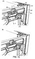
- Figure 3A, 3B and 3C show the latching mechanism 22 in a second, retracted position, in which the latching mechanism is operated to release the locking engagement between the sidewalls 14, 16 and end walls 18, 20 of container 10.
- Figure 3B shows a slightly different, non preferred, configuration for the spring 52 and end 34 of the latching bar 32.
- button 30 is depressed inwardly, as shown by arrow A, and this in turn increases the angle ⁇ , and the length of the secttion 32" of the latching bar 32 between the central portion 32' and the projection 42', as shown in Figure 3A .
- depressing button 30 pulls the latching bar 32 towards the centre of the end wall, against the biasing action of leaf spring 52 which moves further inwardly behind rib 18', so as to retract the end 34 thereof from the recess 44 in the side wall as shown in Figure 3C .
- the latching mechanism 22 is thus disengaged, and the sidewalls 14, 16 and end walls 18, 20 are released from locking engagement. This allows the container 10 to be collapsed.
- the end 34 of the latching bar 32 slides over an abutment 56 in the sidewall whilst the button 30 remains depressed, so that the end wall may be folded inwardly over the base of the container, by pivoting about lower hinge 24.
- there remains a biasing force against leaf spring 52 as shown in Figure 4C .
- the button 30 is released, as shown by arrow B.
- the latching bar 32 then returns to the extended position, under the biasing force of leaf spring 52.
- the projecting end 34 of latching bar 32 is accommodated in a large indentation 58 formed in the side wall, but is not lockingly engaged therein. It will be appreciated that the button 30 may be released whilst collapsing the end wall, once the ends of the latching bar 34, 36 are positioned for alignment with the indentation 58.
- the recess 44 is defined by a rib projecting from the internal surface of the side wall which has a generally flat configuration, no indentation 58 is required,. Instead the extended end 34 of the latching bar is accommodated inside the side wall, in front of the rib.
- the latching mechanism of the above-described embodiment is convenient to use.
- the user can simply and easily release both ends of the container simultaneously, using only one hand for each end.
- the latching bar of the first preferred embodiment is configured with a kink to allow a change of orientation of the latching bar, and thus enable its retraction and extension, it will be appreciated that other forms of connecting the button to a main portion of the latching bar, enabling corresponding movement, are possible and contemplated.
- the kink allows the latching mechanism to be formed in one piece, instead of separate components which require assembly.
- Figures 6 to 9 show a second, preferred embodiment of the present invention, which is similar to the above-described first embodiment, but differs in the manner of operation of the latching mechanism.
- the latching mechanism is configured as an espagnolette, to allow operation of the latch by rotation.
- the latching mechanism 122 comprises a latching member formed as a latching bar 132 mounted on an end wall 118, 120 of a container 110, and adapted so that, in an extended position, its respective ends 134, 136 are received and engaged in corresponding complementary recesses 144, 146 formed on the inner faces of the opposed sidewalls 114 and 116.
- the latching mechanism 122 further comprises a rotatable lever or knob 130, associated with the latching bar 132 for effecting operation of the latching mechanism.
- lever 130 when lever 130 is rotated from a horizontal position, the latching bar 132 is retracted, such that its respective ends 134, 136 are disengaged from the complementary recesses 144, 146 in the sidewalls 114, 116 of the container 110 as described in more detail below.
- Figure 6A, 6B and 6C show the latching mechanism 122 in a first, extended position, in which the latching mechanism provides locking engagement between the sidewalls 114, 116 and end walls 118, 120 of container 110.
- a rotatable lever 130 is mounted in a central aperture in an upper portion of an end wall 118, immediately above a corresponding handle opening 128.
- the lever 130 has a central axle 131, about which it may be rotated in a clockwise or anticlockwise direction, and is shaped for gripping by hand at the underside thereof.
- a latching bar 132 extends along the length of end wall, each side of lever 130, and is pivotally connected thereto by espagnolette rods 132'.
- the lever 130, rods 132' and latching bar 132 may be formed in separate parts from the same resiliently deformable plastics material as the container, and assembled together.
- each rod 132' of the espagnolette is pivotally mounted by respective hinges 133 to the lever 130 at its proximal end and to the latching bar 132 at its distal end.
- the latching bar 132 is mounted within the interior of the end wall, in a manner that enables it to slide laterally, as described in more detail below, without significant movement in other directions.
- the latching bar is biased by a biasing member 150 comprising a resiliently deformable leaf spring 152 adjacent the ends 134, 136 of the latching bar 132, so that the ends 134, 136 are engaged in complementary recesses 144, 146 in the sidewalls of the container, as shown in Figure 6C .
- Spring 152 has a similar configuration and operation to the spring 52 of the first embodiment, and so will not be further described herein.
- the leaf spring 152 holds the ends 134, 136 of latching bar 132 in engagement with the recesses 144, 146 of the end wall, (the boundary of recesses are illustrated by dashed lines), to thereby securely lock together the end wall 118 and the sidewalls 114, 116. It will be appreciated that many other arrangements for biasing the latching bar 132 are possible.
- Figure 7A, 7B and 7C show the latching mechanism 122 in a second, retracted position, in which the latching mechanism is operated to release the locking engagement between the sidewalls 114, 116 and end walls 118, 120 of container 110.
- lever 130 is rotated about axle 131, such that the rods 132' are pivoted about their hinges 133 so that they extend at an angle ⁇ to the vertical, as shown in Figure 7A .
- the latching mechanism 132 is thus disengaged, and the sidewalls and end walls are released form locking engagement. This allows the container 110 to be collapsed.
- the end 134 of the latching bar 132 slides over the interior of in the sidewall whilst the lever 130 remains rotated, so that the end wall 118 may be folded inwardly over the base 112 of the container 110, by pivoting about its lower hinge 124. During this stage, there remains a biasing force against leaf spring, as shown in Figure 8B .
- the lever 130 may be released whilst the end wall is folded, as shown in Figures 9A and 9B .
- the lever 130 and portions 132' return to their neutral position, thus extending the latching bar 132 which is accommodated in a large indentation 158 formed in the side wall during and following collapse of the end wall 118 to overlie the base 112.
- the latching mechanism of the above-described embodiment is also convenient to use.
- the user can simply and easily release both ends of the container simultaneously, using only one hand for each end.
- Figures 10 to 14 show a third, preferred embodiment of the present invention, which differs from the first and second embodiments in the configuration of the latching member of the latching mechanism as well as in the manner of operation of the latching mechanism.
- the latching mechanism operates by rotational movement rather than sliding movement between engaged are released positions.
- the latching mechanism 222 comprises a latching member, which is configured as a catch 232.
- the catch comprises a clip 234, mounted on each end wall 218, 220 (not shown) of a container 210, which is configured to be engaged in complementary hooks 244 formed on the inner faces of the opposed sidewalls 214 and 216.
- the latching mechanism 222 is operated by a pivotable lever 230 located on the end wall and associated with the catch 232 located at each end of the end wall. Two possible configurations of the catch 232 of the latching mechanism 222 are described in detail below. As the skilled person will appreciate, other arrangements are possible and contemplated.
- the side walls 224, 226 have an integral flange 227 at each end thereof, which, when the container 210 is in the assembled configuration, overlaps the end walls 218, 220 by a distance sufficient to accommodate engaging parts of the catch 232 between the flange 227 and the adjacent part of the end wall, as described below.
- FIG 11 illustrates one example of a suitable catch 232 for use with the latching mechanism shown in Figure 10 .
- the catch 232 which is shown in vertical cross section along line X-X of Figure 10A in the drawings of Figure 11 , comprises a clip 234' that is pivotally mounted in the end wall 218 and a pair of complementary hooks 224 fixedly mounted on the flanges 227 of each side wall 216.
- the clip 234' extends substantially along the length of end wall 218 (although its cross section varies along its length) whilst a hook 224 is provided adjacent each end thereof behind the corresponding flanges 227 of the side walls.
- a pair of catches 232 are provided between the end wall and adjacent flange 227.
- the latching mechanism 222 is operated by a lever associated with the clip 234' to enable simultaneous release both catches, as described below.
- Clip 234' comprises a hook member 262 at respective ends of the end wall, which extends from a central portion of the clip and is configured to engage in a recess behind hook 224, an upper spring portion 264 located at either side of the centre of the end wall, and a lower lever portion 266 extending substantially along the length of the end wall.
- Clip 234' is mounted to the end wall 218 along its length by a substantially horizontally extending hinge 268 behind the hook member 262 to permit pivotal rotation about the hinge 268, and thus engagement and release of the hook member 262 from the hooks 224.
- Clip 234' is formed integrally from a resiliently deformable material, preferably the same material as the container 210.
- Figure 11A shows the position of the catch 232 when container 210 is in an assembled or erect position.
- the catch 232 is engaged so as to lock the sidewalls and end walls together.
- This is the configuration shown in Figure 10A .
- the hook member 262 of clip 234' is engaged by latching in the recess behind hook 224 on the interior surface of flange 227.
- the upper edge 270 of spring portion 264 contacts the adjacent surface 218' of end wall 218, and the lower edge of lever portion 266 extends substantially vertically, parallel to the surface of end wall 218.
- lever portion 266 which is located on either side of the centre of the end wall, is exposed by an opening 272, as best seen in Figure 10A , to allow manual operation of the lever portion 266 to disengage the catch 232.
- the lever portion 266 is exposed along substantially the full length of the end wall 218, but is conveniently operated from positions either side of the centre of the end wall, below the spring portions 264.
- Other arrangements are however possible and contemplated.
- the lever portion 266 is pulled outwardly through opening 272, as shown by arrow C, to pivot the clip 234' about hinge 268, and thereby disengage hook member 262 from hook 224.
- the rotation of the lever portion 266 may be achieved by pushing on an associated operating member located on the opposite side of the hinge 268 from the lever portion 266, as shown by arrows C in Figure 10B . Whilst the lever portion 266 is operated, the upper spring portion 264 of clip 234' is compressed against the surface of end wall 218' against its biasing force. This configuration is further illustrated in Figure 10B .
- the side walls 214, 216 and end walls 218, 220 are now released from locking engagement, allowing the end wall 218 to be folded inwardly about its lower hinge 224, and thus collapse the container 210, as shown in Figures 10C and 11C .
- the lever portion 266 may be released, as shown in Figures 10D and 11D , and the biasing force of spring portion 264 returns the clip to its initial configuration.
- the collapsed container 210 can be reassembled to the erect configuration by reversing the operation of the latching mechanism, as shown in Figures 12A to 12D , which shall not be described in detail herein. Nevertheless, it should be noted that the container 210 can be assembled without operation of the lever portion 266.
- the surface of the edge of the hook member 262 of clip 234' and the surface of the edge of the hook 224 of the catch are shaped with an angle to allow the surfaces to ride over each other when the side and end walls are brought together during assembly, as best seen in Figures 12B and 12C .
- the manual force used in erecting the walls of the container causes the automatic engagement of the clip.
- FIG 13 illustrates another example of a suitable catch 232 for use with the latching mechanism shown in Figure 10 .
- the catch 232 which is shown in vertical cross section along lines X-X (top view) and Y-Y (bottom view), comprises a clip 234" that is pivotally mounted in the end wall 218 and a pair of complementary hooks 224 fixedly mounted on the respective adjacent flanges 227 of the side walls 214, 216.
- the clip 234" extends substantially along the length of end wall 218 (although its cross section varies along its length), whilst a hook 224 is provided adjacent each end thereof behind the corresponding flanges 227 of the side walls.
- a pair of catches 232 are provided between the end wall and adjacent flange 227.
- the latching mechanism 222 is operated by a lever associated with the clip 234" on either side of the centre of each end wall to simultaneously release both catches, as described below.
- Clip 234" comprises an upper, wedge shaped portion 282 which extends substantially along the length of the end wall and is pivotable about an axis 288 opposite a curved surface 282' thereof.
- the axis 288 is defined by a horizontally extending axle that extends along at least part of the length of the clip and is connected to rotate the wedge shaped portion 282 as described herein.
- Clip 234" further comprises and a lower lever portion 286 located either side of the centre of the end wall.
- a biasing member comprising a leaf spring 284, also located on either side of the centre of the end wall, is formed above the wedge portion 282 of the clip ( Figure 13A , top view), to bias the clip in an engaged position, where the surface 282' of wedge portion 286 is received within a complementary-shaped recess of hook 224 on the flange 227, as shown in Figure 13A , bottom view.
- leaf spring 284 is formed as an over-centre spring, although other configurations for the biasing member are possible and contemplated.
- lever portion 286 is exposed by an opening 272 in the end wall, to allow manual operation of the lever portion 266 to disengage the catch 232.
- Clip 234" is formed integrally from a resiliently deformable material, preferably the same material as the container 210.
- the lever portion 286 is pulled outwardly through opening 272, as shown by arrow C, to pivot the clip 234" about axis 288, and thereby disengage wedge portion 282 from hook 224.
- the rotation of the lever portion 266 may be achieved by pushing on an associated operating member 266' located on the opposite side of the hinge 268 to the lever portion 266, instead of pulling the lever portion 286, as shown by arrows C in Figure 10B .
- the collapsed container 210 can be reassembled to the erect configuration by reversing the operation of the latching mechanism, as shown in Figures 14A to 14D , which shall not be described in detail herein. Nevertheless, it should be noted that the container 210 can be assembled without operation of the lever portion 286.
- the curved surface of wedge portion 282 of clip 234' and the surface of the edge of the hook 224 of the catch are shaped with an angle to allow the surfaces to ride over each other when the side and end walls are brought together during assembly, as best seen in Figures 14B and 14C .
- the manual force used in erecting the walls of the container causes the automatic engagement of the clip.
- the latching mechanism of the embodiment of Figure 10 is convenient to use.
- the user can simply and easily release both ends of the container simultaneously, using only one hand for each end.
- biasing means can take any appropriate form suitable for biasing the latch in an engaged or disengaged position.
- actuator can take different forms from those described, where appropriate.
- features of each embodiment can be used in combination with features of the other embodiments, or with other known configurations. It is intended to include all such variations, modifications and equivalents which fall within the scope of the present invention.
Abstract
Description
- The present invention relates to a container, and, more particularly, to a collapsible container for consumer-products that has an easily releasable locking mechanism.
- Collapsible containers are well known for use in the transport and display of consumer products. Typically, the containers are formed of plastics material and comprise a base, a pair of opposed sidewalls, and a pair of opposed end walls. Both the sidewalls and end walls are hinged to the base at the lower edges thereof, so that the container can be collapsed into a substantially flat position when not in use.
- In the container disclosed in co-pending UK Patent application No
GB0710088.6 - Various mechanisms are known to provide lockable engagement between the sidewalls and end walls of collapsible containers when in the assembled or erect position. However, known mechanisms can be unreliable or awkward to use, and may require two hands to be used for the release of each end wall. This can make collapsing the containers time-consuming, and may cause irritation to users.
- Accordingly, an improved locking mechanism is desired, which provides reliable locking engagement between the sidewalls and end walls of a collapsible container when in the assembled position, but which is more easily released than known mechanisms.
- According to a first aspect, the present invention provides a latching mechanism for providing locking engagement between the sidewalls and end walls of a collapsible container, the latching mechanism comprising a latching member, biasing means for biasing the latching member in an engaged position in which the latching member provides locking engagement between a side wall and an end wall, and an actuator operable against the biasing means, to move the latching member to a disengaged position in which the latching member is released so as to disengage said sidewall and end wall.
- In one embodiment, the latching member comprises a latching bar, the biasing means biases the latching bar in an extended position, and the actuator is operable against the biasing means, to move the latching bar to a retracted position.
- The actuator may comprise a button which, when depressed, causes retraction of the latching bar. Alternatively, the actuator may comprise a rotatable lever, which, when rotated, causes retraction of the latching bar in the manner of an espagnolette. Other manually operable mechanisms for the actuator are possible and contemplated.
- Preferably, a latching bar is mounted on each end wall of a collapsible container. The actuator may be mounted above, below or adjacent an aperture in each end wall which defines a handle opening. In this way, the actuators may be easily and simultaneously operated by a user to collapse a container, immediately after handling the container, such as lifting it from one position to another.
- In an embodiment, at least one end of the latching bar is received in a complementary recess in the sidewall of the container. Preferably, both ends of the latching bar are received in complementary recesses in the opposed sidewalls of the container.
- In one embodiment, the actuator is located towards the centre of an end wall, and latching bar extends from either side thereof. In one arrangement, the latching bar is configured with a kink, which is adapted to slide over a projection, to thereby move the latching bar towards the actuator. In this way, the latching bar and button may be formed in one piece. Other methods for connecting the actuator to the latching bar, to enable retraction thereof, are possible and contemplated.
- In an embodiment, the actuator is configured to change an orientation of at least a portion of the latching bar, so as to reduce its effective length along the lateral direction, parallel to the end wall.
- In another embodiment, the latching mechanism comprises a clip, and the biasing means biases the clip to engage with a complementary recess. The actuator is operable against the biasing means, to disengage the clip from the recess.
- In one embodiment, the clip is pivotally mounted on one of a side wall or an end wall, and the recess is formed in the other of the side wall or end wall, and the actuator is operable to pivot the clip to engage and disengage it from the recess.
- The actuator may be located in a central portion of an end wall, and the clip and recess provided between the end wall and a flange of the side wall that overlies the end wall in an assembled configuration.
- Preferably the biasing means comprises at least one leaf spring, which is compressed against its biasing action by operation of the actuator. For example, the leaf spring may be compressed against a surface of the end wall.
- Other preferred and optional features and advantages of the present invention will be apparent from the following description and accompanying claims.
- Embodiments of the present invention will now be described, by way of example only, with reference to the accompanying drawings, in which:
-
Figure 1 is a perspective view of a container having a latching mechanism according to a first preferred embodiment of the present invention; -
Figure 2A is a perspective view,Figure 2B is a schematic, lateral cross sectional view along line A-A andFigure 2C is a detailed cross sectional view along line B-B of the latching mechanism ofFigure 1 in an engaged or extended position, with the container assembled; -
Figure 3A is a perspective view,Figure 3B is a schematic, lateral cross sectional view along line A-A andFigure 3C is a detailed cross sectional view along line B-B of the latching mechanism ofFigure 1 in a disengaged or retracted position, with the container assembled; -
Figure 4A is a perspective view,Figure 4B is a schematic, lateral cross sectional view along line A-A andFigure 4C is a detailed cross sectional view along line B-B of the latching mechanism ofFigure 1 in a disengaged or retracted position during collapse of the container; -
Figures 5A and 5B are schematic and detailed cross sectional views, along lines A-A and B-B respectively, of the latching mechanism when the container is in the collapsed position; -
Figure 6A is an end view,Figure 6B a perspective view andFigure 6C a detailed cross sectional view along line B-B of a latching mechanism of another preferred embodiment of the present invention in an engaged or extended position, with the container assembled; -
Figure 7A is an end view,Figure 7B is a perspective view andFigure 7C is a detailed cross sectional view along line B-B of the latching mechanism ofFigure 6 in a disengaged or retracted position, with the container assembled; -
Figure 8A is a perspective view andFigure 8B is a detailed cross sectional view along line B-B of the latching mechanism ofFigure 6 , actuated in a disengaged or retracted position during collapse of the container; -
Figure 9A is a perspective view andFigure 9B is a detailed cross sectional view along line B-B of the latching mechanism ofFigure 6 , released to a retracted position during collapse of the container; -
Figures 10A to 10D are perspective views of a container including a latching mechanism forming yet another preferred embodiment of the present invention, in different configurations of use; -
Figure 11A to 11D are schematic cross sectional views of a first example of a latch for the latching mechanism ofFigure 10 , in different configurations during disengagement of the latch; -
Figure 12A to 12D are schematic cross sectional views along line X-X of the latch ofFigure 11 , in different configurations during engagement of the latch; -
Figure 13A to 13D are schematic cross sectional views of a second example of a latch (bottom view - along line X-X ), for the latching mechanism ofFigure 10 and the corresponding biasing means and actuator ( top view - along line X-X), in different configurations during disengagement of the latch, with the corresponding view ofFigures 10A-10D alongside, and -
Figure 14A to 14D are similar schematic cross sectional views of the latch, and biasing means and actuator ofFigure 13 , in different configurations during engagement of the latch, with the corresponding perspective view alongside. - In some of the drawings, for ease of illustration, only parts of a container, and corresponding latching mechanism, are shown and described below. It will be appreciated that the parts not illustrated have a similar or equivalent configuration and operate in a similar manner to the parts shown. In different embodiments, like features have been accorded the same of similar reference numerals.
-
Figure 1 illustrates acontainer 10 in accordance with a first, preferred embodiment of the present invention. Thecontainer 10 comprises arectangular base 12, a pair ofopposed sidewalls opposed end walls Sidewalls end walls hinges 24, at their lower edges, to thebase 12. -
Container 10 is typically formed by injection moulding from a suitable plastics material, with a pattern ofopenings 26 in thebase 10 andwalls 14 to 20 to minimize the weight of theunfilled container 10. Ahandle opening 28 is provided in a central, upper area of eachside wall end wall container 10. As the skilled person will appreciate, the shape, configuration and dimensions of thecontainer 10, including the relative proportions and thicknesses of thebase 12 andwalls 14 to 20 are chosen according to the design requirements. Thebase 12 andwalls 14 to 20, and other parts ofcontainer 10, are typically moulded as separate parts and assembled together by snap-fit connection or otherwise. -
Container 10 is collapsible from an assembled or erect configuration, as shown inFigure 1 , in which alatching mechanism 22 secures theside walls end walls end walls base 12, and theside walls end walls container 10 is substantially flat. In particular, thelatching mechanism 22 is manually operated by a user to release theend walls side walls respective hinge 24 which connects to the base thereof. Once theend walls base 12, theside walls end walls - In accordance with this first, preferred embodiment, and as illustrated further in
Figures 2 to 5 , thelatching mechanism 22 comprises a latching member formed as alatching bar 32 mounted substantially horizontally on anend wall container 10, and adapted so that, in an extended position, itsrespective ends complementary recesses 44, 46 formed on the inner faces of theopposed sidewalls latching mechanism 22 further comprises adepressable button 30, associated with, and in particular integrally formed with, thelatching bar 32. When thebutton 30 is pushed inwardly, thelatching bar 32 is retracted, such that itsrespective ends complementary recesses 44, 46 as described in more detail below. -
Figure 2A, 2B and 2C show thelatching mechanism 22 in a first, extended position, in which the latching mechanism provides locking engagement between thesidewalls end walls container 10. As shown inFigure 1 andFigure 2A , adepressable button 30 is mounted in a central aperture in an upper portion of anend wall 18, immediately above a corresponding handle opening 28. Thelatching bar 32, only half of which is shown inFigures 2A, 2B and 2C , extends laterally from each side ofbutton 30, and is formed integrally therewith of a resiliently deformable material. In particular, thebutton 30 has a front 30a andsides 30b, 30c which project toward the inner surface ofend wall 18, and the latchingbar 32 extends substantially orthogonally from thesides 30b, 30c for an initial or central portion 32'. Furthermore, the latchingbar 32 is adapted to extend withinend wall 18 between a plurality of abutments orprojections 42, 42' formed in theend wall 18, which provides a guide path for the latchingbar 32 as it moves between the extended position and a retracted position. - Significantly, the latching
bar 32 is shaped with akink 48 or deformation which conforms around a projection 42' at a location between the operatingbutton 30 and theend 34 thereof. Thekink 48 is adapted to slide over projection 42' to change the orientation of asection 32" of the latching bar between the central portion 32' and projection 42'. Thesection 32" of the latching bar defines an angle θ to the vertical (parallel to the end wall) , as shown inFigure 2A and discussed further below. - In addition, a biasing member 50 comprising a resiliently
deformable leaf spring 52 is provided adjacent theends bar 32 in the extended position, as shown inFigure 2C . Thespring 52 is formed from a cut-out central part of the latchingbar 32, adjacent itsend 34, and is curved inwardly so that it extends behind a vertically extending rib 18' on the interior surface of theend wall 18 as shown inFigure 2C . The abutment thespring 52 against of the rib 18' effects a biasing action on the latchingbar 32 into the extended position. - When the
operating button 30 is positioned in its normal, resting position, as shown most clearly inFigure 2A , theleaf spring 52 holds theend 34 of latchingbar 32 in engagement with therecess 44 of the end wall, to thereby securely lock together the sidewall and end wall. It will be appreciated that the recess may be defined by any appropriate moulded shape in the side wall, and thus may take a variety of forms, according to design requirements. For example, therecess 44 may comprise a gap behind a projecting rib from the side wall that provides sufficient space to accommodate anend 34 of the latchingbar 32. -
Figure 3A, 3B and 3C show thelatching mechanism 22 in a second, retracted position, in which the latching mechanism is operated to release the locking engagement between the sidewalls 14, 16 and endwalls container 10. (Note thatFigure 3B shows a slightly different, non preferred, configuration for thespring 52 and end 34 of the latching bar 32). In particular,button 30 is depressed inwardly, as shown by arrow A, and this in turn increases the angle θ, and the length of thesecttion 32" of the latchingbar 32 between the central portion 32' and the projection 42', as shown inFigure 3A . Thus, the action of depressingbutton 30 pulls the latchingbar 32 towards the centre of the end wall, against the biasing action ofleaf spring 52 which moves further inwardly behind rib 18', so as to retract theend 34 thereof from therecess 44 in the side wall as shown inFigure 3C . - The
latching mechanism 22 is thus disengaged, and thesidewalls walls container 10 to be collapsed. In particular, as shown inFigures 4A, 4B and 4C , theend 34 of the latchingbar 32 slides over anabutment 56 in the sidewall whilst thebutton 30 remains depressed, so that the end wall may be folded inwardly over the base of the container, by pivoting aboutlower hinge 24. During this stage, there remains a biasing force againstleaf spring 52, as shown inFigure 4C . - Once the
end wall 18 has been fully collapsed to overlie thebase 18 of the container, as shown inFigures 5A and 5B thebutton 30 is released, as shown by arrow B. The latchingbar 32 then returns to the extended position, under the biasing force ofleaf spring 52. The projectingend 34 of latchingbar 32 is accommodated in alarge indentation 58 formed in the side wall, but is not lockingly engaged therein. It will be appreciated that thebutton 30 may be released whilst collapsing the end wall, once the ends of the latchingbar indentation 58. In addition, it will be appreciated that if therecess 44 is defined by a rib projecting from the internal surface of the side wall which has a generally flat configuration, noindentation 58 is required,. Instead theextended end 34 of the latching bar is accommodated inside the side wall, in front of the rib. - As the skilled person will appreciate, the latching mechanism of the above-described embodiment is convenient to use. In particular, it is possible for a user to hold the container at it ends using respective handle openings, and to release the latching mechanism by simply depressing the buttons on each end wall using just the thumb. Thus, the user can simply and easily release both ends of the container simultaneously, using only one hand for each end. Conveniently, it is unnecessary for the user to change the position of his or her hands, to collapse the container, immediately after lifting or moving the container using the handles provided in the end walls.
- Whilst the latching bar of the first preferred embodiment is configured with a kink to allow a change of orientation of the latching bar, and thus enable its retraction and extension, it will be appreciated that other forms of connecting the button to a main portion of the latching bar, enabling corresponding movement, are possible and contemplated. However, advantageously the kink allows the latching mechanism to be formed in one piece, instead of separate components which require assembly.
-
Figures 6 to 9 show a second, preferred embodiment of the present invention, which is similar to the above-described first embodiment, but differs in the manner of operation of the latching mechanism. In particular, the latching mechanism is configured as an espagnolette, to allow operation of the latch by rotation. - In particular, the
latching mechanism 122 comprises a latching member formed as a latchingbar 132 mounted on anend wall 118, 120 of acontainer 110, and adapted so that, in an extended position, its respective ends 134, 136 are received and engaged in correspondingcomplementary recesses opposed sidewalls 114 and 116. Thelatching mechanism 122 further comprises a rotatable lever orknob 130, associated with the latchingbar 132 for effecting operation of the latching mechanism. Specifically, whenlever 130 is rotated from a horizontal position, the latchingbar 132 is retracted, such that its respective ends 134, 136 are disengaged from thecomplementary recesses sidewalls 114, 116 of thecontainer 110 as described in more detail below. -
Figure 6A, 6B and 6C show thelatching mechanism 122 in a first, extended position, in which the latching mechanism provides locking engagement between thesidewalls 114, 116 and endwalls 118, 120 ofcontainer 110. As shown inFigure 6A , arotatable lever 130 is mounted in a central aperture in an upper portion of anend wall 118, immediately above acorresponding handle opening 128. In particular, thelever 130 has acentral axle 131, about which it may be rotated in a clockwise or anticlockwise direction, and is shaped for gripping by hand at the underside thereof. A latchingbar 132 extends along the length of end wall, each side oflever 130, and is pivotally connected thereto by espagnolette rods 132'. Thelever 130, rods 132' and latchingbar 132 may be formed in separate parts from the same resiliently deformable plastics material as the container, and assembled together. - As shown in
Figures 6A and 6B , when the latchingbar 132 is in the extended position, thelever 130 is in a neutral position in which thelever 130 is level about itsaxle 131, and the rods 132', on either side thereof, extend substantially horizontally, i.e. parallel to the base 112 of thecontainer 110. Each rod 132' of the espagnolette is pivotally mounted by respective hinges 133 to thelever 130 at its proximal end and to the latchingbar 132 at its distal end. The latchingbar 132 is mounted within the interior of the end wall, in a manner that enables it to slide laterally, as described in more detail below, without significant movement in other directions. In the extended position of the latching mechanism, as illustrated inFigure 6 , the latching bar is biased by a biasing member 150 comprising a resiliently deformable leaf spring 152 adjacent theends bar 132, so that the ends 134, 136 are engaged incomplementary recesses Figure 6C . Spring 152 has a similar configuration and operation to thespring 52 of the first embodiment, and so will not be further described herein. - Thus, when the
lever 130 is positioned in a neutral position, as shown most clearly inFigure 6A , the leaf spring 152 holds theends bar 132 in engagement with therecesses end wall 118 and thesidewalls 114, 116. It will be appreciated that many other arrangements for biasing the latchingbar 132 are possible. -
Figure 7A, 7B and 7C show thelatching mechanism 122 in a second, retracted position, in which the latching mechanism is operated to release the locking engagement between thesidewalls 114, 116 and endwalls 118, 120 ofcontainer 110. In particular,lever 130 is rotated aboutaxle 131, such that the rods 132' are pivoted about their hinges 133 so that they extend at an angle θ to the vertical, as shown inFigure 7A . This shortens the distance d between thelever 130 and the distal end of rod 132' as shown by dashed line inFigure 7A . Thus, the action ofrotating lever 130 pulls the latchingbar 132 towards the centre of theend wall 118, against the biasing action of leaf spring 152, so as to retract theends recesses Figure 7C . - The
latching mechanism 132 is thus disengaged, and the sidewalls and end walls are released form locking engagement. This allows thecontainer 110 to be collapsed. In particular, as shown inFigures 8A and 8B theend 134 of the latchingbar 132 slides over the interior of in the sidewall whilst thelever 130 remains rotated, so that theend wall 118 may be folded inwardly over the base 112 of thecontainer 110, by pivoting about itslower hinge 124. During this stage, there remains a biasing force against leaf spring, as shown inFigure 8B . - The
lever 130 may be released whilst the end wall is folded, as shown inFigures 9A and 9B . In particular, as shown inFigure 9A , upon release oflever 130, thelever 130 and portions 132' return to their neutral position, thus extending the latchingbar 132 which is accommodated in alarge indentation 158 formed in the side wall during and following collapse of theend wall 118 to overlie the base 112. - As the skilled person will appreciate, the latching mechanism of the above-described embodiment is also convenient to use. In particular, it is possible for a user to hold the container at it ends using respective handle openings, and to release the latching mechanism by simply rotating the underside of
lever 130. Thus, the user can simply and easily release both ends of the container simultaneously, using only one hand for each end. Conveniently, it is unnecessary for the user to significantly change the position of his or her hands, to collapse the container, immediately after lifting or moving the container using the handles provided in the end walls. -
Figures 10 to 14 show a third, preferred embodiment of the present invention, which differs from the first and second embodiments in the configuration of the latching member of the latching mechanism as well as in the manner of operation of the latching mechanism. In particular, the latching mechanism operates by rotational movement rather than sliding movement between engaged are released positions. - In accordance with this third, preferred embodiment, the
latching mechanism 222 comprises a latching member, which is configured as acatch 232. In particular, the catch comprises aclip 234, mounted on eachend wall 218, 220 (not shown) of a container 210, which is configured to be engaged in complementary hooks 244 formed on the inner faces of the opposed sidewalls 214 and 216. Thelatching mechanism 222 is operated by a pivotable lever 230 located on the end wall and associated with thecatch 232 located at each end of the end wall. Two possible configurations of thecatch 232 of thelatching mechanism 222 are described in detail below. As the skilled person will appreciate, other arrangements are possible and contemplated. - As illustrated in
Figures 10A-10D , theside walls 224, 226 have anintegral flange 227 at each end thereof, which, when the container 210 is in the assembled configuration, overlaps theend walls 218, 220 by a distance sufficient to accommodate engaging parts of thecatch 232 between theflange 227 and the adjacent part of the end wall, as described below. As the skilled person will appreciate, it would be equally possible to provide the flanges on the side walls and reposition the catches accordingly. -
Figure 11 illustrates one example of asuitable catch 232 for use with the latching mechanism shown inFigure 10 . In particular, thecatch 232, which is shown in vertical cross section along line X-X ofFigure 10A in the drawings ofFigure 11 , comprises a clip 234' that is pivotally mounted in theend wall 218 and a pair ofcomplementary hooks 224 fixedly mounted on theflanges 227 of each side wall 216. - It should be noted that the clip 234' extends substantially along the length of end wall 218 (although its cross section varies along its length) whilst a
hook 224 is provided adjacent each end thereof behind the correspondingflanges 227 of the side walls. Thus, for each end wall, a pair ofcatches 232 are provided between the end wall andadjacent flange 227. Thelatching mechanism 222 is operated by a lever associated with the clip 234' to enable simultaneous release both catches, as described below. - Clip 234' comprises a
hook member 262 at respective ends of the end wall, which extends from a central portion of the clip and is configured to engage in a recess behindhook 224, anupper spring portion 264 located at either side of the centre of the end wall, and alower lever portion 266 extending substantially along the length of the end wall. Clip 234' is mounted to theend wall 218 along its length by a substantially horizontally extendinghinge 268 behind thehook member 262 to permit pivotal rotation about thehinge 268, and thus engagement and release of thehook member 262 from thehooks 224. Clip 234' is formed integrally from a resiliently deformable material, preferably the same material as the container 210. -
Figure 11A shows the position of thecatch 232 when container 210 is in an assembled or erect position. Thecatch 232 is engaged so as to lock the sidewalls and end walls together. This is the configuration shown inFigure 10A . In particular, thehook member 262 of clip 234' is engaged by latching in the recess behindhook 224 on the interior surface offlange 227. Of note, theupper edge 270 ofspring portion 264 contacts theadjacent surface 218' ofend wall 218, and the lower edge oflever portion 266 extends substantially vertically, parallel to the surface ofend wall 218. The lower edge of thelever portion 266, which is located on either side of the centre of the end wall, is exposed by anopening 272, as best seen inFigure 10A , to allow manual operation of thelever portion 266 to disengage thecatch 232. In the illustrated embodiment, thelever portion 266 is exposed along substantially the full length of theend wall 218, but is conveniently operated from positions either side of the centre of the end wall, below thespring portions 264. Other arrangements are however possible and contemplated. - In particular, and as shown in
Figure 11B , thelever portion 266 is pulled outwardly throughopening 272, as shown by arrow C, to pivot the clip 234' abouthinge 268, and thereby disengagehook member 262 fromhook 224. It will be appreciated that in alternative arrangements, the rotation of thelever portion 266 may be achieved by pushing on an associated operating member located on the opposite side of thehinge 268 from thelever portion 266, as shown by arrows C inFigure 10B . Whilst thelever portion 266 is operated, theupper spring portion 264 of clip 234' is compressed against the surface ofend wall 218' against its biasing force. This configuration is further illustrated inFigure 10B . - The side walls 214, 216 and end
walls 218, 220 are now released from locking engagement, allowing theend wall 218 to be folded inwardly about itslower hinge 224, and thus collapse the container 210, as shown inFigures 10C and11C . During the collapsing stage, thelever portion 266 may be released, as shown inFigures 10D and11D , and the biasing force ofspring portion 264 returns the clip to its initial configuration. - The collapsed container 210 can be reassembled to the erect configuration by reversing the operation of the latching mechanism, as shown in
Figures 12A to 12D , which shall not be described in detail herein. Nevertheless, it should be noted that the container 210 can be assembled without operation of thelever portion 266. In particular, the surface of the edge of thehook member 262 of clip 234' and the surface of the edge of thehook 224 of the catch are shaped with an angle to allow the surfaces to ride over each other when the side and end walls are brought together during assembly, as best seen inFigures 12B and 12C . Thus, the manual force used in erecting the walls of the container causes the automatic engagement of the clip. -
Figure 13 illustrates another example of asuitable catch 232 for use with the latching mechanism shown inFigure 10 . In particular, thecatch 232, which is shown in vertical cross section along lines X-X (top view) and Y-Y (bottom view), comprises aclip 234" that is pivotally mounted in theend wall 218 and a pair ofcomplementary hooks 224 fixedly mounted on the respectiveadjacent flanges 227 of the side walls 214, 216. - It should be noted that the
clip 234" extends substantially along the length of end wall 218 (although its cross section varies along its length), whilst ahook 224 is provided adjacent each end thereof behind the correspondingflanges 227 of the side walls. Thus, for each end wall, a pair ofcatches 232 are provided between the end wall andadjacent flange 227. Thelatching mechanism 222 is operated by a lever associated with theclip 234" on either side of the centre of each end wall to simultaneously release both catches, as described below. -
Clip 234" comprises an upper, wedge shapedportion 282 which extends substantially along the length of the end wall and is pivotable about anaxis 288 opposite a curved surface 282' thereof. Theaxis 288 is defined by a horizontally extending axle that extends along at least part of the length of the clip and is connected to rotate the wedge shapedportion 282 as described herein.Clip 234" further comprises and alower lever portion 286 located either side of the centre of the end wall. A biasing member comprising aleaf spring 284, also located on either side of the centre of the end wall, is formed above thewedge portion 282 of the clip (Figure 13A , top view), to bias the clip in an engaged position, where the surface 282' ofwedge portion 286 is received within a complementary-shaped recess ofhook 224 on theflange 227, as shown inFigure 13A , bottom view. In the illustrated embodiment,leaf spring 284 is formed as an over-centre spring, although other configurations for the biasing member are possible and contemplated. - The lower edge of
lever portion 286 is exposed by anopening 272 in the end wall, to allow manual operation of thelever portion 266 to disengage thecatch 232.Clip 234" is formed integrally from a resiliently deformable material, preferably the same material as the container 210. - As shown in
Figure 13B , thelever portion 286 is pulled outwardly throughopening 272, as shown by arrow C, to pivot theclip 234" aboutaxis 288, and thereby disengagewedge portion 282 fromhook 224. It will be appreciated that in some arrangements, such as that shown in the perspective view, the rotation of thelever portion 266 may be achieved by pushing on an associated operating member 266' located on the opposite side of thehinge 268 to thelever portion 266, instead of pulling thelever portion 286, as shown by arrows C inFigure 10B . Whilst thelever portion 286 is operated, theupper spring portion 284 ofclip 234" is deformed against its biasing force, to "over-centre" the spring, and thus reverse its arcuate shape so that it is compressed against theinner surface 218' of theend wall 218, as shown inFigure 13B . - The side walls and end walls are now released from locking engagement, allowing the
end wall 218 to be folded inwardly about its lower hinge, and thus collapse the container 210, as shown inFigures 10C and11C . During the collapsing stage, thelever portion 286 may be released, whereby theover-centre spring 284 returns to its original shape and biases the clip back to its initial configuration, as shown inFigures 10D and13D . - The collapsed container 210 can be reassembled to the erect configuration by reversing the operation of the latching mechanism, as shown in
Figures 14A to 14D , which shall not be described in detail herein. Nevertheless, it should be noted that the container 210 can be assembled without operation of thelever portion 286. In particular, the curved surface ofwedge portion 282 of clip 234' and the surface of the edge of thehook 224 of the catch are shaped with an angle to allow the surfaces to ride over each other when the side and end walls are brought together during assembly, as best seen inFigures 14B and14C . Thus, the manual force used in erecting the walls of the container causes the automatic engagement of the clip. - As the skilled person will appreciate, the latching mechanism of the embodiment of
Figure 10 is convenient to use. In particular, it is possible for a user to hold the container at it ends using respective handle openings, and to release the latching mechanism by simply operating the lever portion of the clip using just the thumb (by pushing on the operating member) or with the fingers (by pulling on the lever). Thus, the user can simply and easily release both ends of the container simultaneously, using only one hand for each end. Conveniently, it is unnecessary for the user to change the position of his or her hands, to collapse the container, immediately after lifting or moving the container using the handles provided in the end walls. - As the skilled person will appreciate, many variations and modifications can be made to the described embodiments. For example alternative locations, orientations and configurations for the catch, according to the third embodiment, are possible. Whilst the third embodiment has been described with a pair of springs, which form the biasing member, and corresponding lever portions, it would be possible to use just one, or equally three or more.
- In addition, the biasing means can take any appropriate form suitable for biasing the latch in an engaged or disengaged position. Furthermore, the actuator can take different forms from those described, where appropriate. Moreover, features of each embodiment can be used in combination with features of the other embodiments, or with other known configurations. It is intended to include all such variations, modifications and equivalents which fall within the scope of the present invention.
- Some further aspects of the invention can be found in the following paragraphs:
- 1. A collapsible container having a pair of opposed side walls and a pair of opposed end walls and a base, the container including a latching mechanism for providing locking engagement between the sidewalls and end walls, the latching mechanism comprising:
- a latching member;
- biasing means for biasing the latching member in an engaged position in which the latching member provides locking engagement between a side wall and an end wall of the container, and
- an actuator operable against the biasing means, to move the latching member to a disengaged position in which the latching member is released so as to disengage said sidewall and end wall.
- 2. A container as described in paragraph 1, wherein the biasing means is configured to bias the latching member in an extended position, and the actuator is operable against the biasing means, to move the latching member to a retracted position.
- 3. A container as described in paragraph 2, wherein the actuator comprises a button which, when depressed, causes retraction of the latching member.
- 4. A container as described in paragraph 2, wherein the actuator comprises a rotatable lever, which, when rotated, causes retraction of the latching member.
- 5. A container as described in paragraph 4, wherein the actuator is configured to operate as an espagnolette.
- 6. A container as described in any one of paragraphs 1 to 5, wherein a latching member is mounted on at least one end wall of the container.
- 7. A container as described in paragraph 6, wherein an actuator is mounted above, below or adjacent an aperture in the at least one end wall which defines a handle opening.
- 8. A container as described in paragraph 6 or paragraph 7, wherein the container is configured so that, when extended, at least a part of the latching member is received in a complementary recess in an adjacent side wall of the container.
- 9. A container as described in paragraph 8, wherein the latching member comprises a latching bar, and the container is configured so that, when extended, respective ends of the latching bar are received in complementary recesses in the opposed side walls of the container.
- 10. A container as described in paragraph 9, wherein the actuator is located towards the centre of an end wall, and latching bar extends from either side thereof.
- 11. A container as described in
paragraph 10, wherein the latching bar is formed with a kink between the actuator and at least one end thereof, the kink adapted to slide over a projection extending from the end wall, to thereby retract the latching bar towards the actuator. - 12. A container as described in any one of paragraphs 6 to 11, wherein the actuator is configured to change an orientation of at least a portion of the latching member, so as to change its effective length along the lateral direction, parallel to the end wall.
- 13. A container as described in paragraph 1, wherein the latching mechanism comprises a clip, which is biased by the biasing means to engage with a complementary recess, and the actuator is operable against the biasing means, to disengage the clip from the recess.
- 14. A container as described in paragraph 13, wherein the clip is pivotally mounted on one of a side wall or an end wall, and the recess is formed in the other of the side wall or end wall, and the actuator is operable to pivot the clip to engage and disengage it from the recess.
- 15. A container as described in paragraph 13 or
paragraph 14, wherein the actuator is located in a substantially central portion of an end wall, and the clip and recess provided between the end wall and a flange of the side wall. - 16. A container as described in
paragraph 13, 14 or 15, wherein the biasing means comprises at least one leaf spring, which is compressed against its biasing action by operation of the actuator. - 17. A container as described in
paragraph 16, wherein operation of the actuator compresses the leaf spring against a surface of the end wall. - 18. A container as described in any one of the preceding paragraphs, wherein the side walls and end walls define an opening in the top of the container.
- 19. A latching mechanism for a container as described in any one of paragraphs 1 to 18.
Claims (25)
- A collapsible container having a pair of opposed side walls and a pair of opposed end walls and a base, the container including a latching mechanism for providing locking engagement between the sidewalls and end walls, the latching mechanism comprising:a latching member;biasing means for biasing the latching member in an engaged position in which the latching member provides locking engagement between a side wall and an end wall of the container, andan actuator operable against the biasing means, to move the latching member to a disengaged position in which the latching member is released so as to disengage said sidewall and end wall.
- A container as claimed in claim 1 wherein the locking engagement is provided between an end wall and both sidewalls
- A container as claimed in claim 1 or 2, wherein the actuator is operable to release the end wall from the side walls simultaneously.
- A container as claimed in any preceding claim, wherein the latching member is operable between engaged and disengaged positions by rotational movement.
- A container as claimed in any preceding claim, wherein the biasing means is configured to bias the latching member in an extended position, and the actuator is operable against the biasing means, to move the latching member to a retracted position.
- A container as claimed in claim 5, wherein the actuator comprises a rotatable lever, which, when rotated, causes retraction of the latching member.
- A container as claimed in claim 6, wherein the actuator is configured to operate as an espagnolette.
- A container as claimed in any preceding claim, wherein a latching member is mounted on at least one end wall of the container.
- A container as claimed in claim 8, wherein an actuator is mounted above, below or adjacent an aperture in the at least one end wall which defines a handle opening.
- A container as claimed in claim 8 or claim 9, wherein the container is configured so that, when extended, at least a part of the latching member is received in a complementary recess in an adjacent side wall of the container.
- A container as claimed in claim 10, wherein the latching member comprises a latching bar, and the container is configured so that, when extended, respective ends of the latching bar are received in complementary recesses in the opposed side walls of the container.
- A container as claimed in claim 11, wherein the actuator is located towards the centre of an end wall, and latching bar extends from either side thereof.
- A container as claimed in claim 12, wherein the latching bar is formed with a kink between the actuator and at least one end thereof, the kink adapted to slide over a projection extending from the end wall, to thereby retract the latching bar towards the actuator.
- A container as claimed in any one of claims 8 to 13, wherein the actuator is configured to change an orientation of at least a portion of the latching member, so as to change its effective length along the lateral direction, parallel to the end wall.
- A container as claimed in any preceding claim, wherein the actuator is located in a substantially central portion of an end wall.
- A container as claimed in any preceding claim, wherein the biasing means comprises at least one leaf spring, which is compressed against its biasing action by operation of the actuator.
- A container as claimed in claim 16, wherein operation of the actuator compresses the leaf spring against a surface of the end wall.
- A container as claimed in any preceding claim, wherein the latching mechanism comprises a clip, which is biased by the biasing means to engage with a complementary recess, and the actuator is operable against the biasing means, to disengage the clip from the recess.
- A container as claimed in claim 18, wherein the clip extends substantially along the length of the end wall.
- A container as claimed in claim 18 or 19, wherein the latching member comprises a catch located at each end of the end wall.
- A container as claimed in claim 20, wherein the latching member is operable to enable simultaneous release of both catches of the end wall.
- A container as claimed in claim 20 or 21, wherein the actuator comprises a pivotable lever for operating the latching member, wherein the pivotable lever is located at the end wall and associated with both catches located at each end of the end wall.
- A container as claimed in any of claims 18 to 22, wherein the clip is pivotally mounted on one of a side wall or an end wall, and the recess is formed in the other of the side wall or end wall, and the actuator is operable to pivot the clip to engage and disengage it from the recess.
- A container as claimed in any of claims 18 to 23, wherein the clip and recess provided between the end wall and a flange of the side wall.
- A latching mechanism for a container according to any one of claims 1 to 24.
Applications Claiming Priority (2)
| Application Number | Priority Date | Filing Date | Title |
|---|---|---|---|
| GB0717892A GB2452750B (en) | 2007-09-13 | 2007-09-13 | Container |
| EP08253028.8A EP2036825B1 (en) | 2007-09-13 | 2008-09-15 | A collapsible container |
Related Parent Applications (3)
| Application Number | Title | Priority Date | Filing Date |
|---|---|---|---|
| EP08253028.8A Division EP2036825B1 (en) | 2007-09-13 | 2008-09-15 | A collapsible container |
| EP08253028.8A Division-Into EP2036825B1 (en) | 2007-09-13 | 2008-09-15 | A collapsible container |
| EP08253028.8 Division | 2008-09-15 |
Publications (3)
| Publication Number | Publication Date |
|---|---|
| EP2338803A1 true EP2338803A1 (en) | 2011-06-29 |
| EP2338803B1 EP2338803B1 (en) | 2018-07-25 |
| EP2338803B8 EP2338803B8 (en) | 2018-10-24 |
Family
ID=38658920
Family Applications (2)
| Application Number | Title | Priority Date | Filing Date |
|---|---|---|---|
| EP08253028.8A Revoked EP2036825B1 (en) | 2007-09-13 | 2008-09-15 | A collapsible container |
| EP10171140.6A Not-in-force EP2338803B8 (en) | 2007-09-13 | 2008-09-15 | A collapsible container |
Family Applications Before (1)
| Application Number | Title | Priority Date | Filing Date |
|---|---|---|---|
| EP08253028.8A Revoked EP2036825B1 (en) | 2007-09-13 | 2008-09-15 | A collapsible container |
Country Status (4)
| Country | Link |
|---|---|
| EP (2) | EP2036825B1 (en) |
| DE (1) | DE202008017658U1 (en) |
| ES (2) | ES2606403T3 (en) |
| GB (1) | GB2452750B (en) |
Cited By (2)
| Publication number | Priority date | Publication date | Assignee | Title |
|---|---|---|---|---|
| RU2463224C2 (en) * | 2008-02-11 | 2012-10-10 | Фритц Шефер Гмбх | Device for unlocking folding side walls of boxes or containers |
| WO2016112866A1 (en) * | 2015-01-16 | 2016-07-21 | 上海鸿研物流技术有限公司 | Folding box |
Families Citing this family (17)
| Publication number | Priority date | Publication date | Assignee | Title |
|---|---|---|---|---|
| AT507858B1 (en) † | 2009-02-12 | 2011-04-15 | Leisch Beratungs Und Beteiligungs Gmbh | folding |
| DE102009049103A1 (en) | 2009-04-15 | 2010-11-04 | Ifco Systems Gmbh | Crate with foldable and removable outer walls |
| DE102009049185A1 (en) | 2009-04-15 | 2011-01-05 | Ifco Systems Gmbh | Crate with foldable side walls with stable sidewall structure |
| DK2408677T3 (en) | 2009-04-15 | 2013-04-22 | Ifco Systems Gmbh | Container with foldable side wall |
| DE102009049186A1 (en) | 2009-04-15 | 2010-11-04 | Ifco Systems Gmbh | Crate with foldable and self-locking side walls |
| DE102009049184A1 (en) * | 2009-04-15 | 2010-11-04 | Ifco Systems Gmbh | Crate with foldable side walls and locking mechanisms with overload protection |
| ATE520600T1 (en) | 2009-05-28 | 2011-09-15 | Aldi Einkauf Gmbh & Co Ohg | TRANSPORT AND/OR STORAGE CONTAINERS |
| DE102009023069B4 (en) | 2009-05-28 | 2011-07-14 | Aldi Einkauf GmbH & Co. oHG, 45476 | Transport and / or storage container |
| DE202009007608U1 (en) | 2009-05-28 | 2009-08-06 | Walther Faltsysteme Gmbh | Transport and / or storage container |
| ES2350791B1 (en) * | 2009-06-15 | 2011-11-16 | Sp Berner Plastic Group, S.L. | FOLDING BOX |
| DE202009015184U1 (en) | 2009-11-09 | 2010-03-25 | bekuplast Kunststoffverarbeitungs-Gesellschaft mit beschränkter Haftung | Transport and storage container with locking device |
| DE202010005898U1 (en) | 2010-04-20 | 2010-08-05 | Aldi Einkauf Gmbh & Co. Ohg | Transport and / or storage container |
| CN103429497B (en) * | 2011-02-10 | 2016-08-10 | 埃弗科系统有限公司 | Box body |
| DE102012017295A1 (en) * | 2012-08-31 | 2014-03-06 | Bb-Stanz- Und Umformtechnik Gmbh | Lock for flap |
| US10065763B2 (en) | 2016-09-15 | 2018-09-04 | Arena Packaging, Llc | Wall latching system |
| DE102017102717B3 (en) * | 2017-02-10 | 2017-09-21 | ALDI SÜD Dienstleistungs-GmbH & Co. oHG | Transport and / or storage container |
| RU194604U1 (en) * | 2019-07-29 | 2019-12-17 | Общество с ограниченной ответственностью "Ай-Пласт" | FOLDING CONTAINER |
Citations (7)
| Publication number | Priority date | Publication date | Assignee | Title |
|---|---|---|---|---|
| WO2000068099A1 (en) * | 1999-05-10 | 2000-11-16 | Schoeller Wavin Systems N.V. | Container with lockable side walls |
| CA2309234A1 (en) * | 1999-05-31 | 2000-11-30 | Thomas Gabriel Bela Merey | Foldable container |
| JP2004083113A (en) | 2002-08-29 | 2004-03-18 | Sanko Co Ltd | Folding container |
| US20050098556A1 (en) * | 2002-01-03 | 2005-05-12 | Richard Kellerer | Collapsible container comprising a container base and four collapsible lateral walls |
| EP1655232A1 (en) * | 2003-08-13 | 2006-05-10 | Mitsubishi Plastics Inc. | Folding container |
| EP1746036A1 (en) * | 2005-07-19 | 2007-01-24 | Odesa Gelistirilmis Polimer Yatirimlari Ve Dis Tic | Locking system for a foldable crate |
| EP1785360A1 (en) * | 2005-11-02 | 2007-05-16 | LINPAC Materials Handling Limited | Collapsible container |
Family Cites Families (7)
| Publication number | Priority date | Publication date | Assignee | Title |
|---|---|---|---|---|
| GB710088A (en) | 1950-11-14 | 1954-06-09 | Jardine John Ltd | Improvements relating to typewriters |
| CA2273556A1 (en) * | 1999-05-31 | 2000-11-30 | Thomas Gabriel Bela Merey | Foldable container |
| CA2330996C (en) * | 2001-01-15 | 2007-08-21 | Norseman Plastics Limited | Biased latch hinge |
| US7017766B2 (en) * | 2003-03-10 | 2006-03-28 | Rehrig Pacific Company | Collapsible container with side wall latching capability |
| EP1544116B1 (en) * | 2003-12-15 | 2009-07-15 | Arca Systems AB | Locking system for a collapsible container |
| SE527894C2 (en) | 2004-04-23 | 2006-07-04 | Arca Systems Internat Ab | Locking system for a container and a container with such locking system |
| DE202007015378U1 (en) * | 2007-08-20 | 2008-02-21 | Odesa Gelistirilmis Polimer Yatirimlari Ve Dis Ticaret A.S. | Sliding lock device for collapsible boxes |
-
2007
- 2007-09-13 GB GB0717892A patent/GB2452750B/en not_active Expired - Fee Related
-
2008
- 2008-09-15 EP EP08253028.8A patent/EP2036825B1/en not_active Revoked
- 2008-09-15 ES ES08253028.8T patent/ES2606403T3/en active Active
- 2008-09-15 DE DE200820017658 patent/DE202008017658U1/en not_active Expired - Lifetime
- 2008-09-15 EP EP10171140.6A patent/EP2338803B8/en not_active Not-in-force
- 2008-09-15 ES ES10171140.6T patent/ES2692330T3/en active Active
Patent Citations (7)
| Publication number | Priority date | Publication date | Assignee | Title |
|---|---|---|---|---|
| WO2000068099A1 (en) * | 1999-05-10 | 2000-11-16 | Schoeller Wavin Systems N.V. | Container with lockable side walls |
| CA2309234A1 (en) * | 1999-05-31 | 2000-11-30 | Thomas Gabriel Bela Merey | Foldable container |
| US20050098556A1 (en) * | 2002-01-03 | 2005-05-12 | Richard Kellerer | Collapsible container comprising a container base and four collapsible lateral walls |
| JP2004083113A (en) | 2002-08-29 | 2004-03-18 | Sanko Co Ltd | Folding container |
| EP1655232A1 (en) * | 2003-08-13 | 2006-05-10 | Mitsubishi Plastics Inc. | Folding container |
| EP1746036A1 (en) * | 2005-07-19 | 2007-01-24 | Odesa Gelistirilmis Polimer Yatirimlari Ve Dis Tic | Locking system for a foldable crate |
| EP1785360A1 (en) * | 2005-11-02 | 2007-05-16 | LINPAC Materials Handling Limited | Collapsible container |
Cited By (3)
| Publication number | Priority date | Publication date | Assignee | Title |
|---|---|---|---|---|
| RU2463224C2 (en) * | 2008-02-11 | 2012-10-10 | Фритц Шефер Гмбх | Device for unlocking folding side walls of boxes or containers |
| WO2016112866A1 (en) * | 2015-01-16 | 2016-07-21 | 上海鸿研物流技术有限公司 | Folding box |
| US10532850B2 (en) | 2015-01-16 | 2020-01-14 | Shanghai Hongyan Returnable Transit Transit Packagings Co., Ltd. | Folding box |
Also Published As
| Publication number | Publication date |
|---|---|
| DE202008017658U1 (en) | 2010-07-22 |
| GB2452750B (en) | 2012-06-20 |
| ES2692330T3 (en) | 2018-12-03 |
| ES2606403T3 (en) | 2017-03-23 |
| EP2338803B1 (en) | 2018-07-25 |
| GB0717892D0 (en) | 2007-10-24 |
| EP2036825B1 (en) | 2016-09-14 |
| EP2036825A1 (en) | 2009-03-18 |
| EP2338803B8 (en) | 2018-10-24 |
| GB2452750A (en) | 2009-03-18 |
Similar Documents
| Publication | Publication Date | Title |
|---|---|---|
| EP2338803A1 (en) | A collapsible container | |
| US6290081B1 (en) | Foldable container | |
| US6073790A (en) | Folding container with releasably locking side walls | |
| CA2327942C (en) | Collapsible container | |
| US7322110B2 (en) | Knife with trigger actuator for retractable blade | |
| EP2133180B1 (en) | A tool container assembly | |
| US8567631B2 (en) | Tool box | |
| CN102616452B (en) | There is the container of snap close | |
| US7311220B2 (en) | Collapsible container comprising a container base and four collapsible lateral walls | |
| US6138851A (en) | Container | |
| EP1744961A1 (en) | A locking system provided with a handle to be used in a container | |
| CN107073700B (en) | Saw frame | |
| GB2451380A (en) | Collapsible container with bail arm support facilitating stacking | |
| CZ290012B6 (en) | Collapsible plastic container with releasably blocked sidewalls | |
| PL201026B1 (en) | Container, especially reusable container, comprising collapsible lateral walls | |
| WO2000068099A1 (en) | Container with lockable side walls | |
| US20150322717A1 (en) | Folding step stool | |
| US7748667B1 (en) | Folding portable laptop stand | |
| US6443074B1 (en) | Folding table | |
| US9422087B1 (en) | Foldable crate and locking mechanisms therefor | |
| CA2309234A1 (en) | Foldable container | |
| AU2003235566A1 (en) | A Handle | |
| US20070084358A1 (en) | Refuse bin including a compacting mechanism | |
| EP2354025A2 (en) | Container | |
| CA2715583A1 (en) | Container with a retractable handle |
Legal Events
| Date | Code | Title | Description |
|---|---|---|---|
| PUAI | Public reference made under article 153(3) epc to a published international application that has entered the european phase |
Free format text: ORIGINAL CODE: 0009012 |
|
| AC | Divisional application: reference to earlier application |
Ref document number: 2036825 Country of ref document: EP Kind code of ref document: P |
|
| AK | Designated contracting states |
Kind code of ref document: A1 Designated state(s): AT BE BG CH CY CZ DE DK EE ES FI FR GB GR HR HU IE IS IT LI LT LU LV MC MT NL NO PL PT RO SE SI SK TR |
|
| AX | Request for extension of the european patent |
Extension state: AL BA MK RS |
|
| 17P | Request for examination filed |
Effective date: 20111229 |
|
| 17Q | First examination report despatched |
Effective date: 20120913 |
|
| TPAC | Observations filed by third parties |
Free format text: ORIGINAL CODE: EPIDOSNTIPA |
|
| TPAC | Observations filed by third parties |
Free format text: ORIGINAL CODE: EPIDOSNTIPA |
|
| STAA | Information on the status of an ep patent application or granted ep patent |
Free format text: STATUS: EXAMINATION IS IN PROGRESS |
|
| GRAP | Despatch of communication of intention to grant a patent |
Free format text: ORIGINAL CODE: EPIDOSNIGR1 |
|
| STAA | Information on the status of an ep patent application or granted ep patent |
Free format text: STATUS: GRANT OF PATENT IS INTENDED |
|
| INTG | Intention to grant announced |
Effective date: 20180207 |
|
| GRAS | Grant fee paid |
Free format text: ORIGINAL CODE: EPIDOSNIGR3 |
|
| GRAA | (expected) grant |
Free format text: ORIGINAL CODE: 0009210 |
|
| STAA | Information on the status of an ep patent application or granted ep patent |
Free format text: STATUS: THE PATENT HAS BEEN GRANTED |
|
| AC | Divisional application: reference to earlier application |
Ref document number: 2036825 Country of ref document: EP Kind code of ref document: P |
|
| AK | Designated contracting states |
Kind code of ref document: B1 Designated state(s): AT BE BG CH CY CZ DE DK EE ES FI FR GB GR HR HU IE IS IT LI LT LU LV MC MT NL NO PL PT RO SE SI SK TR |
|
| RAP1 | Party data changed (applicant data changed or rights of an application transferred) |
Owner name: LINPAC ALLIBERT LIMITED |
|
| REG | Reference to a national code |
Ref country code: GB Ref legal event code: FG4D |
|
| REG | Reference to a national code |
Ref country code: CH Ref legal event code: EP |
|
| REG | Reference to a national code |
Ref country code: AT Ref legal event code: REF Ref document number: 1021487 Country of ref document: AT Kind code of ref document: T Effective date: 20180815 |
|
| RAP2 | Party data changed (patent owner data changed or rights of a patent transferred) |
Owner name: SCHOELLER ALLIBERT GMBH |
|
| REG | Reference to a national code |
Ref country code: IE Ref legal event code: FG4D |
|
| REG | Reference to a national code |
Ref country code: DE Ref legal event code: R096 Ref document number: 602008056188 Country of ref document: DE |
|
| REG | Reference to a national code |
Ref country code: FR Ref legal event code: PLFP Year of fee payment: 11 |
|
| REG | Reference to a national code |
Ref country code: CH Ref legal event code: PK Free format text: BERICHTIGUNG B8 |
|
| REG | Reference to a national code |
Ref country code: DE Ref legal event code: R081 Ref document number: 602008056188 Country of ref document: DE Owner name: SCHOELLER ALLIBERT GMBH, DE Free format text: FORMER OWNER: LINPAC ALLIBERT LIMITED, BIRMINGHAM, GB |
|
| REG | Reference to a national code |
Ref country code: NL Ref legal event code: FP |
|
| REG | Reference to a national code |
Ref country code: ES Ref legal event code: FG2A Ref document number: 2692330 Country of ref document: ES Kind code of ref document: T3 Effective date: 20181203 |
|
| REG | Reference to a national code |
Ref country code: LT Ref legal event code: MG4D |
|
| REG | Reference to a national code |
Ref country code: AT Ref legal event code: MK05 Ref document number: 1021487 Country of ref document: AT Kind code of ref document: T Effective date: 20180725 |
|
| PG25 | Lapsed in a contracting state [announced via postgrant information from national office to epo] |
Ref country code: GR Free format text: LAPSE BECAUSE OF FAILURE TO SUBMIT A TRANSLATION OF THE DESCRIPTION OR TO PAY THE FEE WITHIN THE PRESCRIBED TIME-LIMIT Effective date: 20181026 Ref country code: NO Free format text: LAPSE BECAUSE OF FAILURE TO SUBMIT A TRANSLATION OF THE DESCRIPTION OR TO PAY THE FEE WITHIN THE PRESCRIBED TIME-LIMIT Effective date: 20181025 Ref country code: AT Free format text: LAPSE BECAUSE OF FAILURE TO SUBMIT A TRANSLATION OF THE DESCRIPTION OR TO PAY THE FEE WITHIN THE PRESCRIBED TIME-LIMIT Effective date: 20180725 Ref country code: BG Free format text: LAPSE BECAUSE OF FAILURE TO SUBMIT A TRANSLATION OF THE DESCRIPTION OR TO PAY THE FEE WITHIN THE PRESCRIBED TIME-LIMIT Effective date: 20181025 Ref country code: SE Free format text: LAPSE BECAUSE OF FAILURE TO SUBMIT A TRANSLATION OF THE DESCRIPTION OR TO PAY THE FEE WITHIN THE PRESCRIBED TIME-LIMIT Effective date: 20180725 Ref country code: LT Free format text: LAPSE BECAUSE OF FAILURE TO SUBMIT A TRANSLATION OF THE DESCRIPTION OR TO PAY THE FEE WITHIN THE PRESCRIBED TIME-LIMIT Effective date: 20180725 Ref country code: PL Free format text: LAPSE BECAUSE OF FAILURE TO SUBMIT A TRANSLATION OF THE DESCRIPTION OR TO PAY THE FEE WITHIN THE PRESCRIBED TIME-LIMIT Effective date: 20180725 Ref country code: FI Free format text: LAPSE BECAUSE OF FAILURE TO SUBMIT A TRANSLATION OF THE DESCRIPTION OR TO PAY THE FEE WITHIN THE PRESCRIBED TIME-LIMIT Effective date: 20180725 Ref country code: IS Free format text: LAPSE BECAUSE OF FAILURE TO SUBMIT A TRANSLATION OF THE DESCRIPTION OR TO PAY THE FEE WITHIN THE PRESCRIBED TIME-LIMIT Effective date: 20181125 |
|
| PG25 | Lapsed in a contracting state [announced via postgrant information from national office to epo] |
Ref country code: LV Free format text: LAPSE BECAUSE OF FAILURE TO SUBMIT A TRANSLATION OF THE DESCRIPTION OR TO PAY THE FEE WITHIN THE PRESCRIBED TIME-LIMIT Effective date: 20180725 Ref country code: HR Free format text: LAPSE BECAUSE OF FAILURE TO SUBMIT A TRANSLATION OF THE DESCRIPTION OR TO PAY THE FEE WITHIN THE PRESCRIBED TIME-LIMIT Effective date: 20180725 |
|
| REG | Reference to a national code |
Ref country code: DE Ref legal event code: R097 Ref document number: 602008056188 Country of ref document: DE |
|
| PG25 | Lapsed in a contracting state [announced via postgrant information from national office to epo] |
Ref country code: RO Free format text: LAPSE BECAUSE OF FAILURE TO SUBMIT A TRANSLATION OF THE DESCRIPTION OR TO PAY THE FEE WITHIN THE PRESCRIBED TIME-LIMIT Effective date: 20180725 Ref country code: EE Free format text: LAPSE BECAUSE OF FAILURE TO SUBMIT A TRANSLATION OF THE DESCRIPTION OR TO PAY THE FEE WITHIN THE PRESCRIBED TIME-LIMIT Effective date: 20180725 Ref country code: MC Free format text: LAPSE BECAUSE OF FAILURE TO SUBMIT A TRANSLATION OF THE DESCRIPTION OR TO PAY THE FEE WITHIN THE PRESCRIBED TIME-LIMIT Effective date: 20180725 Ref country code: CZ Free format text: LAPSE BECAUSE OF FAILURE TO SUBMIT A TRANSLATION OF THE DESCRIPTION OR TO PAY THE FEE WITHIN THE PRESCRIBED TIME-LIMIT Effective date: 20180725 |
|
| REG | Reference to a national code |
Ref country code: CH Ref legal event code: PL |
|
| PG25 | Lapsed in a contracting state [announced via postgrant information from national office to epo] |
Ref country code: SK Free format text: LAPSE BECAUSE OF FAILURE TO SUBMIT A TRANSLATION OF THE DESCRIPTION OR TO PAY THE FEE WITHIN THE PRESCRIBED TIME-LIMIT Effective date: 20180725 Ref country code: DK Free format text: LAPSE BECAUSE OF FAILURE TO SUBMIT A TRANSLATION OF THE DESCRIPTION OR TO PAY THE FEE WITHIN THE PRESCRIBED TIME-LIMIT Effective date: 20180725 |
|
| PLBE | No opposition filed within time limit |
Free format text: ORIGINAL CODE: 0009261 |
|
| STAA | Information on the status of an ep patent application or granted ep patent |
Free format text: STATUS: NO OPPOSITION FILED WITHIN TIME LIMIT |
|
| REG | Reference to a national code |
Ref country code: BE Ref legal event code: MM Effective date: 20180930 |
|
| REG | Reference to a national code |
Ref country code: IE Ref legal event code: MM4A |
|
| PG25 | Lapsed in a contracting state [announced via postgrant information from national office to epo] |
Ref country code: LU Free format text: LAPSE BECAUSE OF NON-PAYMENT OF DUE FEES Effective date: 20180915 |
|
| 26N | No opposition filed |
Effective date: 20190426 |
|
| PG25 | Lapsed in a contracting state [announced via postgrant information from national office to epo] |
Ref country code: IE Free format text: LAPSE BECAUSE OF NON-PAYMENT OF DUE FEES Effective date: 20180915 |
|
| PG25 | Lapsed in a contracting state [announced via postgrant information from national office to epo] |
Ref country code: CH Free format text: LAPSE BECAUSE OF NON-PAYMENT OF DUE FEES Effective date: 20180930 Ref country code: BE Free format text: LAPSE BECAUSE OF NON-PAYMENT OF DUE FEES Effective date: 20180930 Ref country code: SI Free format text: LAPSE BECAUSE OF FAILURE TO SUBMIT A TRANSLATION OF THE DESCRIPTION OR TO PAY THE FEE WITHIN THE PRESCRIBED TIME-LIMIT Effective date: 20180725 Ref country code: LI Free format text: LAPSE BECAUSE OF NON-PAYMENT OF DUE FEES Effective date: 20180930 |
|
| PGFP | Annual fee paid to national office [announced via postgrant information from national office to epo] |
Ref country code: NL Payment date: 20190923 Year of fee payment: 12 Ref country code: DE Payment date: 20190823 Year of fee payment: 12 Ref country code: FR Payment date: 20190923 Year of fee payment: 12 Ref country code: IT Payment date: 20190920 Year of fee payment: 12 |
|
| PGFP | Annual fee paid to national office [announced via postgrant information from national office to epo] |
Ref country code: GB Payment date: 20190924 Year of fee payment: 12 |
|
| PG25 | Lapsed in a contracting state [announced via postgrant information from national office to epo] |
Ref country code: MT Free format text: LAPSE BECAUSE OF NON-PAYMENT OF DUE FEES Effective date: 20180915 |
|
| PGFP | Annual fee paid to national office [announced via postgrant information from national office to epo] |
Ref country code: ES Payment date: 20191023 Year of fee payment: 12 |
|
| PG25 | Lapsed in a contracting state [announced via postgrant information from national office to epo] |
Ref country code: TR Free format text: LAPSE BECAUSE OF FAILURE TO SUBMIT A TRANSLATION OF THE DESCRIPTION OR TO PAY THE FEE WITHIN THE PRESCRIBED TIME-LIMIT Effective date: 20180725 |
|
| PG25 | Lapsed in a contracting state [announced via postgrant information from national office to epo] |
Ref country code: PT Free format text: LAPSE BECAUSE OF FAILURE TO SUBMIT A TRANSLATION OF THE DESCRIPTION OR TO PAY THE FEE WITHIN THE PRESCRIBED TIME-LIMIT Effective date: 20180725 Ref country code: HU Free format text: LAPSE BECAUSE OF FAILURE TO SUBMIT A TRANSLATION OF THE DESCRIPTION OR TO PAY THE FEE WITHIN THE PRESCRIBED TIME-LIMIT; INVALID AB INITIO Effective date: 20080915 |
|
| PG25 | Lapsed in a contracting state [announced via postgrant information from national office to epo] |
Ref country code: CY Free format text: LAPSE BECAUSE OF FAILURE TO SUBMIT A TRANSLATION OF THE DESCRIPTION OR TO PAY THE FEE WITHIN THE PRESCRIBED TIME-LIMIT Effective date: 20180725 |
|
| REG | Reference to a national code |
Ref country code: DE Ref legal event code: R119 Ref document number: 602008056188 Country of ref document: DE |
|
| REG | Reference to a national code |
Ref country code: NL Ref legal event code: MM Effective date: 20201001 |
|
| GBPC | Gb: european patent ceased through non-payment of renewal fee |
Effective date: 20200915 |
|
| PG25 | Lapsed in a contracting state [announced via postgrant information from national office to epo] |
Ref country code: NL Free format text: LAPSE BECAUSE OF NON-PAYMENT OF DUE FEES Effective date: 20201001 |
|
| PG25 | Lapsed in a contracting state [announced via postgrant information from national office to epo] |
Ref country code: DE Free format text: LAPSE BECAUSE OF NON-PAYMENT OF DUE FEES Effective date: 20210401 Ref country code: FR Free format text: LAPSE BECAUSE OF NON-PAYMENT OF DUE FEES Effective date: 20200930 |
|
| PG25 | Lapsed in a contracting state [announced via postgrant information from national office to epo] |
Ref country code: GB Free format text: LAPSE BECAUSE OF NON-PAYMENT OF DUE FEES Effective date: 20200915 |
|
| PG25 | Lapsed in a contracting state [announced via postgrant information from national office to epo] |
Ref country code: IT Free format text: LAPSE BECAUSE OF NON-PAYMENT OF DUE FEES Effective date: 20200915 |
|
| REG | Reference to a national code |
Ref country code: ES Ref legal event code: FD2A Effective date: 20220118 |
|
| PG25 | Lapsed in a contracting state [announced via postgrant information from national office to epo] |
Ref country code: ES Free format text: LAPSE BECAUSE OF NON-PAYMENT OF DUE FEES Effective date: 20200916 |