EP2338753A1 - Système de frein de stationnement pouvant être actionné de manière électrique et procédé de commande d'un système de frein de stationnement pouvant être actionné de manière électrique - Google Patents
Système de frein de stationnement pouvant être actionné de manière électrique et procédé de commande d'un système de frein de stationnement pouvant être actionné de manière électrique Download PDFInfo
- Publication number
- EP2338753A1 EP2338753A1 EP10195129A EP10195129A EP2338753A1 EP 2338753 A1 EP2338753 A1 EP 2338753A1 EP 10195129 A EP10195129 A EP 10195129A EP 10195129 A EP10195129 A EP 10195129A EP 2338753 A1 EP2338753 A1 EP 2338753A1
- Authority
- EP
- European Patent Office
- Prior art keywords
- control
- valve device
- vent
- port
- control valve
- Prior art date
- Legal status (The legal status is an assumption and is not a legal conclusion. Google has not performed a legal analysis and makes no representation as to the accuracy of the status listed.)
- Granted
Links
- 238000000034 method Methods 0.000 title claims abstract description 6
- 238000013022 venting Methods 0.000 claims description 28
- 230000003068 static effect Effects 0.000 claims description 7
- 238000012546 transfer Methods 0.000 claims description 3
- 238000009423 ventilation Methods 0.000 abstract description 4
- 230000007704 transition Effects 0.000 description 9
- 230000000694 effects Effects 0.000 description 4
- 238000010586 diagram Methods 0.000 description 3
- 210000003746 feather Anatomy 0.000 description 3
- 230000009471 action Effects 0.000 description 2
- 230000008859 change Effects 0.000 description 2
- 230000007423 decrease Effects 0.000 description 2
- 230000003247 decreasing effect Effects 0.000 description 2
- 239000000853 adhesive Substances 0.000 description 1
- 230000001070 adhesive effect Effects 0.000 description 1
- 230000000740 bleeding effect Effects 0.000 description 1
- 238000004891 communication Methods 0.000 description 1
- 230000008878 coupling Effects 0.000 description 1
- 238000010168 coupling process Methods 0.000 description 1
- 238000005859 coupling reaction Methods 0.000 description 1
- 230000001419 dependent effect Effects 0.000 description 1
- 238000013461 design Methods 0.000 description 1
- 238000005553 drilling Methods 0.000 description 1
- 230000003993 interaction Effects 0.000 description 1
- 238000012423 maintenance Methods 0.000 description 1
- 230000008569 process Effects 0.000 description 1
- 238000010926 purge Methods 0.000 description 1
- 238000005096 rolling process Methods 0.000 description 1
- 238000012360 testing method Methods 0.000 description 1
- 238000011144 upstream manufacturing Methods 0.000 description 1
Images


Classifications
-
- B—PERFORMING OPERATIONS; TRANSPORTING
- B60—VEHICLES IN GENERAL
- B60T—VEHICLE BRAKE CONTROL SYSTEMS OR PARTS THEREOF; BRAKE CONTROL SYSTEMS OR PARTS THEREOF, IN GENERAL; ARRANGEMENT OF BRAKING ELEMENTS ON VEHICLES IN GENERAL; PORTABLE DEVICES FOR PREVENTING UNWANTED MOVEMENT OF VEHICLES; VEHICLE MODIFICATIONS TO FACILITATE COOLING OF BRAKES
- B60T13/00—Transmitting braking action from initiating means to ultimate brake actuator with power assistance or drive; Brake systems incorporating such transmitting means, e.g. air-pressure brake systems
- B60T13/10—Transmitting braking action from initiating means to ultimate brake actuator with power assistance or drive; Brake systems incorporating such transmitting means, e.g. air-pressure brake systems with fluid assistance, drive, or release
- B60T13/66—Electrical control in fluid-pressure brake systems
- B60T13/68—Electrical control in fluid-pressure brake systems by electrically-controlled valves
- B60T13/686—Electrical control in fluid-pressure brake systems by electrically-controlled valves in hydraulic systems or parts thereof
Definitions
- the invention further relates to a method for transferring such an electrically operated parking brake system from a park state to a driving state in which the control and vent valve device is transferred from a venting the control valve means venting in the vent port of the control valve means ventilated state, whereby the pressure on the Vent connection increases.
- the present disclosure is concerned with electrically actuatable parking brake systems, as described, for example, in US Pat DE 10 2008 007 877 B3 are described.
- a central safety-related requirement for such systems is that a power failure must not lead to a change in state of the parking brakes- is the parking brake in its park state, so even in case of power failure, the park state must be maintained, so unintentional rolling away of the truck in each case to prevent the parking brake is in a driving condition, so in case of power failure, the parking brake must not be abruptly inserted, as this can lead to dangerous situations while driving.
- bistable control valves can be used. These can be controlled electrically or pneumatically.
- the present invention is concerned with pneumatically controllable switching valve devices, which are integrated into an electrically actuated parking brake system in such a way that a bistability is given and thus meets the safety-related requirements mentioned above.
- Electrically actuated parking brake systems and in particular the mentioned pneumatic control valve devices are to be designed so that absolute switching safety is ensured. If the pressure conditions in the parking brake system are thus changed in order to effect a changeover of the control valve device, then the control valve device must be able to switch safely, and this under any external circumstances, in particular even at low temperatures, which can hinder a switching of the switching valve device, in particular due to increased frictional forces.
- the invention has for its object to provide a concept in which the bistability of a pneumatic control valve device for an electrically actuated parking brake system is ensured, with absolute switching safety even at low Temperatures should be given.
- solutions are to be offered, which are accompanied by the least possible wear of the system components and in particular the pneumatic control valve device.
- the invention is based on the generic state of the art mentioned above in that in the second switching state, a difference between an effective ventilation surface of the control piston facing the vent port and an effective area of the control piston to be ventilated via the second working port and the control input, taking into account the control cam in its second switching state driving spring force sufficient to convict the control piston at identical pressures on both effective surfaces in its first switching state.
- the effective area to be ventilated via the second working connection and the control input is preferably a sum of two surfaces, one surface facing a working space accessible via the working ports and the other facing a control space passing through the control input is accessible.
- the invention further relates to a method for transferring such an electrically operated parking brake system from a parking state to a driving state in which the control and vent valve device is transferred from a venting the control valve means venting in the venting port of the control valve means ventilating state, whereby the pressure on the Venting connection increases, wherein the driving condition is achieved in that set at vented vent port static pressure conditions at the vent port, the second working port and the control input of the control valve device, which cause a switching of the control valve means, and that the switching state of the control valve means by switching the control valve and vent valve means of the venting connection of the control valve means venting in the venting state does not change is. It is therefore not necessary to use the pressure changes and the resulting dynamic pressure conditions, to switch the control valve device.
- circuits include 3/2-way valves as central facilities. These can each be replaced by two 2/2-way valves, the principles explained with reference to the 3/2-way valves are then to be transferred to the 2/2-way valve groups in the context of the present invention.
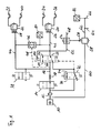
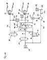
- FIG. 1 shows a circuit diagram of an electrically operated parking brake system.
- the electrically actuated parking brake system is connected via a check valve 10 with a compressed air treatment system, not shown.
- the check valve 10 is followed by an optional filter unit 12, via which compressed air is supplied to a supply solenoid valve 14, which is designed as a 2/2-way valve.
- a working port 20 of a control valve device 22 is connected via a supply line section 16 and an optional throttle 18.
- the control valve device 22 is designed as a pneumatically controllable 3/2-way valve.
- a second working connection 24 of the control valve device 22 leads to a control input 26 of a trailer control module 30. This operates a supply connection 34 and a control connection 36 of the trailer coupling.
- a control input 28 of another trailer control module 32 is connected via a trailer control line branch 44 to the supply line branch 16. It has a supply connection 38 and a control connection 40.
- the trailer control line branches 42, 44 are connected to inputs of a select-low valve 46 whose output is connected via a control line 48 to a control input 50 of the control valve device 22.
- the select-low valve operates so that at its output, that is in the control line 48, the lower input pressure is present, that is, the lower pressure from the two trailer control line branches 42, 44.
- the control line 48 is still on a relay control line 52 and a Shuttle valve 54 with the relay control input 56 of a relay valve 58 in conjunction.
- the relay valve 58 receives compressed air from a location upstream of the supply solenoid valve 14 via a relay supply line 60.
- a relay output line leads to line branches 64, 66 to which spring-loaded cylinders, not shown, are connected.
- a service brake line 68 is also connected.
- a vent port 70 of the control valve device 22 a port 74 of a control and vent valve device 72 is connected.
- Another port 76 of the control and vent valve device 72 is supplied with compressed air from a point between the filter unit 12 and the supply solenoid valve 14.
- a designed as a 2/2-way valve vent valve 78 is provided, which is connected to the supply line section 16.
- the second working port of the control valve device 22 is vented via the control and vent valve device 72, so that in the absence of pressurization via the service brake line 68 and the control input 56 of the relay valve 58 is vented. Consequently, the spring storage cylinders, not shown, are depressurized, so that the parking brake is in its parking position.
- the control and ventilation valve device 72 is now switched over. Consequently, pressure builds up in particular in the control line branch 48, the relay control line 52 and at the relay control input 56. This pressure leads to the passage of the relay valve 58 when a threshold value is exceeded, so that the spring-loaded cylinders are subjected to pressure and the parking brake is released.
- the pressure in the control line 48 is the driving force for switching the control valve 22.
- this switching can take place before the control and venting device 72 is again converted into its illustrated de-energized state. If the switching takes place while the control and vent valve device 72 is still in its energized state, then the control valve device 22 is to be provided with such active surfaces that the pending at the terminals pressures generate forces which overcome the spring force of the control valve device 22.
- the shift strategy which allows switching the control valve device 22 against the spring force after switching the control and vent valve device 72 in its re-energized state, based on dynamic processes explained later.
- control valve device 22 has switched, so the pressure on the Further build control inputs 50 and 56 of the control valve device 22 and the relay valve 58, since the corresponding line branches are now supplied from the supply line section 16 with compressed air.
- the control valve device 22 remains in the absence of further switching operations of the solenoid valves 14, 72, 78 in their state. A power failure has no influence on this, so that no unintentional transfer of the parking brake system can take place in their park state.
- switchover is carried out as planned by energizing the venting solenoid valve 78 so that the pressure in the supply line section and thus also at the control inputs 50, 56 of the control valve device 22 and of the relay valve 56 decreases.
- Another switching state of the system is when the vent valve 78, the supply solenoid valve 14 and the control and vent valve means 72 are energized so that the control input 50 of the control valve means 22 and the control input 56 of the relay valve are vented, the control input 26 of the trailer control valve 30th while being ventilated.
- These pressure conditions in the system cause a release of the trailer brake while the parking brake of the towing vehicle is inserted or remains. So there is a trailer test state, in which it can be checked whether it can be held solely by the parking brake of the towing vehicle, the entire train consisting of tractor and trailer.
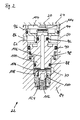
- FIG. 2 shows a control valve device 22 with a sliding valve seat 108 in a driving position.
- a valve housing 84 houses the control valve device 22, which has a first working connection 20, a second working connection 24, a control input 50 and a venting connection 70. Further, a relay terminal 86 is provided, which is connected to the relay control line 52 and at which the same pressure as at the control input 50 prevails.
- the control valve device 22 includes a control piston 100 which is guided in the valve housing 84 via three O-rings 88, 90, 92 acting as radial seals, or a sleeve 96 sealingly inserted in the valve housing 84 via an O-ring 94. It is provided a spring 98 which acts on the control piston 100 with force.
- the control piston 100 has a central bore 102 through which a working space 104 can communicate with a venting space 106. In the illustrated state of the control valve device 22, however, this communication is prevented by the sealingly acting first valve seat 108.
- the first valve seat 108 comes into effect by an interaction of the control piston 100 with a valve seat piston 110, wherein the valve seat piston 110 is supported on the valve housing 84 via a spring 112.
- FIG. 2 illustrated switching state of the control valve device 22 is present when 50 compressed air is supplied via the working port 20 and the control input, while the vent port 70 is vented.
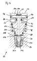
- FIG. 3 shows the control valve device 22 with sliding valve seat 108 in an intermediate position.
- FIG. 4 shows the control valve device 22 with sliding valve seat 108 in a parking position. If the control valve device 22 of the in FIG. 2 shown switching state, the driving state, in the in FIG. 4 shown switching state, the park state, transferred, the working port 20 is vented. As a result, the springs 98, 112 can move the control piston 100 against the decreasing pressure in the working space. In this case, the displaceable valve seat piston 110 follows the control piston 100. A thus assumed intermediate state is in FIG. 3 shown. The control piston 100 has already moved in a direction decreasing the working space 104, but the valve seat 108 still seals the working space 104 against the vent space 106.
- this spring 112 impedes the initial movement of the control piston 100 at the transition from the parking position according to FIG. 4 according to the driving position FIG. 2 Not.
- the vent port 70 in the state according to FIG. 4 is pressurized, also builds a pressure in the working space 104 and, in external wiring according to FIG. 1 , at the control input 50 of the control valve device 22.
- the force of the spring 98 and the static friction of the O-rings 88, 90, 92 must be overcome, but not the force of the spring 112.
- the initial movement of the spool 100 is assisted by ventilating the vent outlet 70.
- This is done by energizing the control and vent solenoid valve 72. If the valve seat piston 110 is then arranged in the valve housing 84 in such a way that its the valve seat 108 facing away, so the spring 112 facing surface 124 is acted upon by the supplied via the vent port 70, so The resulting force in a useful manner supports the movement of the control piston in the direction of the second valve seat 114.
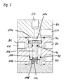
- FIG. 5 shows a control valve device 22 with a fixed valve seat 108 'in a driving position.
- the control valve device 22 according to FIG. 5 no sliding valve seat piston. Rather, the valve seat 108 'is fixed. Nevertheless, the transition from the in FIG. 5 illustrated driving position to the in FIG. 6 illustrated parking position can be supported by the vent port 70 is vented while the work port 20 is vented.
- control valve devices are guided and sealed by three O-rings 88, 90, 92.
- the active surfaces of the control piston 100 are designed so that a transition from the parking position to the driving position with energized control and ventilation solenoid valve device 72 according to FIG. 1 he follows. Once the control valve device 22 is then switched to the driving position, the control and vent valve device 72 can be transferred without effect for the switching state of the control valve device 22 in its de-energized state.
- FIG. 7 shows a control valve device 22 with a two radial seals 88, 92 having control piston 100 in a driving position.
- FIG. 8 shows the control valve device 22 with a two radial seals 88, 92 having control piston 100 in a parking position.
- the control valve device 22 shown here has a control piston 100, which is guided over only two radial seals, namely the O-rings 88, 92.
- the ratios of the active surfaces are taking into account the force of the spring 116 such that the control valve device 22 is not energized by energized control and vent solenoid valve 72 from its in FIG. 8 Parking position shown in their in FIG. 7 shown driving position is transferred.
- the control valve device 22 according to the FIGS. 7 and 8th has a fixed valve seat 108 '. However, it can also be equipped with a sliding valve seat.
- FIGS. 9 to 11 show schematically an electric parking brake system in three different switching states. That in the FIGS. 9 to 11 shown system differs from that in FIG. 1 illustrated system essentially in that in the control line 48, the trailer control line branch 42, and the trailer control line branch 44 leading input port of the select-low valve 46 throttles 118, 120, 122 are provided.
- the control valve device 22 may have a throttle in the venting path of its control piston. Shall now a transition from the in FIG. 9 illustrated state, which corresponds to the parking position, in the in FIG. 11 illustrated state, which corresponds to the driving position, carried out, so first the control and bleed solenoid valve 72 is switched, as in FIG. 10 shown. As related to the FIGS.
- control valve means 22 may be designed so that the thereby adjusting pressure conditions do not lead to a switching of the control valve device 22. If, however, a certain pressure level in the control line 48 has built up after a certain energizing time of the control and venting solenoid valve device 72, then the control valve device 22 can be switched over by switching the control and venting solenoid valve device 72 into its venting connection 70 of the control valve device 22 venting state is transferred. Because of the throttle 118, the pressure at the vent port 70 can namely reduce faster than at the control input 48.
Applications Claiming Priority (1)
| Application Number | Priority Date | Filing Date | Title |
|---|---|---|---|
| DE200910059816 DE102009059816B3 (de) | 2009-12-21 | 2009-12-21 | Elektrisch betätigbares Feststellbremssystem und Verfahren zum Steuern eines elektrisch betätigbaren Feststellbremssystems |
Publications (2)
| Publication Number | Publication Date |
|---|---|
| EP2338753A1 true EP2338753A1 (fr) | 2011-06-29 |
| EP2338753B1 EP2338753B1 (fr) | 2013-05-29 |
Family
ID=43797027
Family Applications (1)
| Application Number | Title | Priority Date | Filing Date |
|---|---|---|---|
| EP20100195129 Active EP2338753B1 (fr) | 2009-12-21 | 2010-12-15 | Système de frein de stationnement pouvant être actionné de manière électrique et procédé de commande d'un système de frein de stationnement pouvant être actionné de manière électrique |
Country Status (2)
| Country | Link |
|---|---|
| EP (1) | EP2338753B1 (fr) |
| DE (1) | DE102009059816B3 (fr) |
Families Citing this family (13)
| Publication number | Priority date | Publication date | Assignee | Title |
|---|---|---|---|---|
| DE102011101438B4 (de) | 2011-05-13 | 2013-05-08 | Knorr-Bremse Systeme für Nutzfahrzeuge GmbH | Parkbremseinrichtung |
| DE102011053707B4 (de) | 2011-09-16 | 2017-01-26 | Haldex Brake Products Aktiebolag | Druckluftaufbereitungseinheit |
| DE102014004933A1 (de) | 2014-04-05 | 2015-10-08 | Man Truck & Bus Ag | Elektrische Federspeicher-Feststellbremse |
| HUE037922T2 (hu) * | 2014-04-09 | 2018-09-28 | Knorr Bremse Systeme Fuer Nutzfahrzeuge Gmbh | Elektropneumatikus parkolófékvezérlõ berendezés |
| DE102015106150A1 (de) | 2015-04-22 | 2016-10-27 | Knorr-Bremse Systeme für Nutzfahrzeuge GmbH | Parkbremseinrichtung für Kraftfahrzeuge |
| DE102015106147A1 (de) | 2015-04-22 | 2016-10-27 | Knorr-Bremse Systeme für Nutzfahrzeuge GmbH | Parkbremseinrichtung für Kraftfahrzeuge |
| DE102015106144A1 (de) | 2015-04-22 | 2016-10-27 | Knorr-Bremse Systeme für Nutzfahrzeuge GmbH | Steuerventileinrichtung für eine Parkbremseinrichtung für Kraftfahrzeuge sowie Parkbremseinrichtung für Kraftfahrzeuge |
| DE102015106145A1 (de) | 2015-04-22 | 2016-10-27 | Knorr-Bremse Systeme für Nutzfahrzeuge GmbH | Parkbremseinrichtung für Kraftfahrzeuge |
| DE102015106146A1 (de) | 2015-04-22 | 2016-10-27 | Knorr-Bremse Systeme für Nutzfahrzeuge GmbH | Parkbremseinrichtung für Kraftfahrzeuge |
| DE102016117784A1 (de) | 2016-09-21 | 2018-03-22 | Knorr-Bremse Systeme für Nutzfahrzeuge GmbH | Parkbremseinrichtung für ein Nutzfahrzeug |
| DE102017007780A1 (de) | 2017-08-16 | 2019-02-21 | Wabco Gmbh | Elektropneumatisches Festellbremsmodul mit direkt gesteuerten Ventilen |
| DE102017120691A1 (de) | 2017-09-07 | 2019-03-07 | Knorr-Bremse Systeme für Nutzfahrzeuge GmbH | Elektropneumatische Parkbremssteuereinrichtung |
| DE102020108947A1 (de) | 2020-03-31 | 2021-09-30 | Zf Cv Systems Global Gmbh | Anhängersteuermodul einer druckmittelbetriebenen Bremsanlage eines Zugfahrzeugs mit einer Ventilanordnung zur Steuerung einer pneumatischen Bremsanlage eines Anhängerfahrzeugs |
Citations (3)
| Publication number | Priority date | Publication date | Assignee | Title |
|---|---|---|---|---|
| US5370449A (en) * | 1993-10-12 | 1994-12-06 | Eaton Corporation | Electrically operated parking brake system |
| DE102008015249A1 (de) * | 2007-03-23 | 2008-09-25 | Knorr-Bremse Systeme für Nutzfahrzeuge GmbH | Druckmittelbetätigte Bremsanlage eines Fahrzeugs mit wenigstens einem bistabilen Schieberventil |
| DE102008007877B3 (de) | 2008-02-06 | 2009-11-26 | Knorr-Bremse Systeme für Nutzfahrzeuge GmbH | Parkbremseinrichtung |
Family Cites Families (2)
| Publication number | Priority date | Publication date | Assignee | Title |
|---|---|---|---|---|
| DE102007051150B4 (de) * | 2007-04-23 | 2010-04-08 | Knorr-Bremse Systeme für Nutzfahrzeuge GmbH | Feststellbremsventil für eine Nutzfahrzeugbremsanlage und damit ausgestattete Nutzfahrzeugbremsanlage |
| DE102007061908B4 (de) * | 2007-12-21 | 2010-01-28 | Knorr-Bremse Systeme für Nutzfahrzeuge GmbH | Parkbremse |
-
2009
- 2009-12-21 DE DE200910059816 patent/DE102009059816B3/de not_active Expired - Fee Related
-
2010
- 2010-12-15 EP EP20100195129 patent/EP2338753B1/fr active Active
Patent Citations (3)
| Publication number | Priority date | Publication date | Assignee | Title |
|---|---|---|---|---|
| US5370449A (en) * | 1993-10-12 | 1994-12-06 | Eaton Corporation | Electrically operated parking brake system |
| DE102008015249A1 (de) * | 2007-03-23 | 2008-09-25 | Knorr-Bremse Systeme für Nutzfahrzeuge GmbH | Druckmittelbetätigte Bremsanlage eines Fahrzeugs mit wenigstens einem bistabilen Schieberventil |
| DE102008007877B3 (de) | 2008-02-06 | 2009-11-26 | Knorr-Bremse Systeme für Nutzfahrzeuge GmbH | Parkbremseinrichtung |
Also Published As
| Publication number | Publication date |
|---|---|
| EP2338753B1 (fr) | 2013-05-29 |
| DE102009059816B3 (de) | 2011-04-28 |
Similar Documents
| Publication | Publication Date | Title |
|---|---|---|
| EP2384943B1 (fr) | Dispositif de soupape, système de frein de stationnement pouvant être actionné de manière électrique et procédé de commande d'un système de frein de stationnement pouvant être actionné de manière électrique | |
| EP2338753B1 (fr) | Système de frein de stationnement pouvant être actionné de manière électrique et procédé de commande d'un système de frein de stationnement pouvant être actionné de manière électrique | |
| EP2547565B1 (fr) | Système de frein de stationnement à commande électrique | |
| DE102015114176C5 (de) | Elektrische Parkbremseinrichtung mit zusätzlicher Energieversorgung | |
| EP2576301B1 (fr) | Système de freinage de stationnement électrique, et procédé pour faire fonctionner un système de freinage de stationnement électrique | |
| EP3755589B1 (fr) | Équipement électropneumatique d'un véhicule | |
| DE102006055570B4 (de) | Feststellbremsvorrichtung mit einer Feststellbremse-Notlöseeinrichtung | |
| EP2338754B1 (fr) | Système de frein de stationnement pouvant être actionné de manière électrique et procédé de commande d'un système de frein de stationnement pouvant être actionné de manière électrique | |
| WO2018172340A1 (fr) | Module de commande de remorque (tcv) intégré doté d'une unité frein à main électropneumatique (eph) externe | |
| EP3694755A1 (fr) | Module de freinage de stationnement électropneumatique pour véhicules utilitaires comprenant des freins de stationnement à ressort accumulateur | |
| EP2298616A2 (fr) | Appareil de commande et procédé de test d'un dispositif de soupape d'un frein de stationnement électrique | |
| EP2731839A2 (fr) | Installation de préparation d'air comprimé et procédé servant à faire fonctionner une installation de préparation d'air comprimé | |
| EP2407355B1 (fr) | Soupape de relais et procédé de fonctionnement d'une soupape de relais | |
| DE19918070B4 (de) | Druckregelvorrichtung für elektro-pneumatische Bremsanlagen von Fahrzeugen, insbesondere Nutzfahrzeugen | |
| EP3286052B1 (fr) | Arrangement de frein de parking pour véhicules | |
| WO2018041284A1 (fr) | Commande pneumatique | |
| EP3286050B1 (fr) | Arrangement de vanne de contrôle pour un frein de parking pour véhicules et arrangement de frein de parking pour véhicules | |
| EP2094547B1 (fr) | Dispositif de frein de stationnement équipé de conduits d'alimentation en air comprimé | |
| EP2384944B1 (fr) | Procédé de commande d'un système de frein de stationnement pouvant être actionné de manière électrique | |
| DE102016100289A1 (de) | Steuerventileinrichtung für eine elektrische Parkbremsvorrichtung und elektrische Parkbremsvorrichtung | |
| DE102009055210B4 (de) | Druckluftanlage |
Legal Events
| Date | Code | Title | Description |
|---|---|---|---|
| PUAI | Public reference made under article 153(3) epc to a published international application that has entered the european phase |
Free format text: ORIGINAL CODE: 0009012 |
|
| AK | Designated contracting states |
Kind code of ref document: A1 Designated state(s): AL AT BE BG CH CY CZ DE DK EE ES FI FR GB GR HR HU IE IS IT LI LT LU LV MC MK MT NL NO PL PT RO RS SE SI SK SM TR |
|
| AX | Request for extension of the european patent |
Extension state: BA ME |
|
| 17P | Request for examination filed |
Effective date: 20111229 |
|
| GRAP | Despatch of communication of intention to grant a patent |
Free format text: ORIGINAL CODE: EPIDOSNIGR1 |
|
| GRAS | Grant fee paid |
Free format text: ORIGINAL CODE: EPIDOSNIGR3 |
|
| GRAA | (expected) grant |
Free format text: ORIGINAL CODE: 0009210 |
|
| AK | Designated contracting states |
Kind code of ref document: B1 Designated state(s): AL AT BE BG CH CY CZ DE DK EE ES FI FR GB GR HR HU IE IS IT LI LT LU LV MC MK MT NL NO PL PT RO RS SE SI SK SM TR |
|
| REG | Reference to a national code |
Ref country code: GB Ref legal event code: FG4D Free format text: NOT ENGLISH |
|
| REG | Reference to a national code |
Ref country code: CH Ref legal event code: EP |
|
| REG | Reference to a national code |
Ref country code: AT Ref legal event code: REF Ref document number: 614185 Country of ref document: AT Kind code of ref document: T Effective date: 20130615 |
|
| REG | Reference to a national code |
Ref country code: IE Ref legal event code: FG4D Free format text: LANGUAGE OF EP DOCUMENT: GERMAN |
|
| REG | Reference to a national code |
Ref country code: DE Ref legal event code: R096 Ref document number: 502010003433 Country of ref document: DE Effective date: 20130801 |
|
| REG | Reference to a national code |
Ref country code: SE Ref legal event code: TRGR |
|
| REG | Reference to a national code |
Ref country code: NL Ref legal event code: T3 |
|
| REG | Reference to a national code |
Ref country code: LT Ref legal event code: MG4D |
|
| PG25 | Lapsed in a contracting state [announced via postgrant information from national office to epo] |
Ref country code: GR Free format text: LAPSE BECAUSE OF FAILURE TO SUBMIT A TRANSLATION OF THE DESCRIPTION OR TO PAY THE FEE WITHIN THE PRESCRIBED TIME-LIMIT Effective date: 20130830 Ref country code: LT Free format text: LAPSE BECAUSE OF FAILURE TO SUBMIT A TRANSLATION OF THE DESCRIPTION OR TO PAY THE FEE WITHIN THE PRESCRIBED TIME-LIMIT Effective date: 20130529 Ref country code: FI Free format text: LAPSE BECAUSE OF FAILURE TO SUBMIT A TRANSLATION OF THE DESCRIPTION OR TO PAY THE FEE WITHIN THE PRESCRIBED TIME-LIMIT Effective date: 20130529 Ref country code: IS Free format text: LAPSE BECAUSE OF FAILURE TO SUBMIT A TRANSLATION OF THE DESCRIPTION OR TO PAY THE FEE WITHIN THE PRESCRIBED TIME-LIMIT Effective date: 20130929 Ref country code: SI Free format text: LAPSE BECAUSE OF FAILURE TO SUBMIT A TRANSLATION OF THE DESCRIPTION OR TO PAY THE FEE WITHIN THE PRESCRIBED TIME-LIMIT Effective date: 20130529 Ref country code: NO Free format text: LAPSE BECAUSE OF FAILURE TO SUBMIT A TRANSLATION OF THE DESCRIPTION OR TO PAY THE FEE WITHIN THE PRESCRIBED TIME-LIMIT Effective date: 20130829 Ref country code: PT Free format text: LAPSE BECAUSE OF FAILURE TO SUBMIT A TRANSLATION OF THE DESCRIPTION OR TO PAY THE FEE WITHIN THE PRESCRIBED TIME-LIMIT Effective date: 20130930 Ref country code: ES Free format text: LAPSE BECAUSE OF FAILURE TO SUBMIT A TRANSLATION OF THE DESCRIPTION OR TO PAY THE FEE WITHIN THE PRESCRIBED TIME-LIMIT Effective date: 20130909 |
|
| PG25 | Lapsed in a contracting state [announced via postgrant information from national office to epo] |
Ref country code: PL Free format text: LAPSE BECAUSE OF FAILURE TO SUBMIT A TRANSLATION OF THE DESCRIPTION OR TO PAY THE FEE WITHIN THE PRESCRIBED TIME-LIMIT Effective date: 20130529 Ref country code: RS Free format text: LAPSE BECAUSE OF FAILURE TO SUBMIT A TRANSLATION OF THE DESCRIPTION OR TO PAY THE FEE WITHIN THE PRESCRIBED TIME-LIMIT Effective date: 20130529 Ref country code: HR Free format text: LAPSE BECAUSE OF FAILURE TO SUBMIT A TRANSLATION OF THE DESCRIPTION OR TO PAY THE FEE WITHIN THE PRESCRIBED TIME-LIMIT Effective date: 20130529 Ref country code: BG Free format text: LAPSE BECAUSE OF FAILURE TO SUBMIT A TRANSLATION OF THE DESCRIPTION OR TO PAY THE FEE WITHIN THE PRESCRIBED TIME-LIMIT Effective date: 20130829 |
|
| PG25 | Lapsed in a contracting state [announced via postgrant information from national office to epo] |
Ref country code: LV Free format text: LAPSE BECAUSE OF FAILURE TO SUBMIT A TRANSLATION OF THE DESCRIPTION OR TO PAY THE FEE WITHIN THE PRESCRIBED TIME-LIMIT Effective date: 20130529 |
|
| PG25 | Lapsed in a contracting state [announced via postgrant information from national office to epo] |
Ref country code: CZ Free format text: LAPSE BECAUSE OF FAILURE TO SUBMIT A TRANSLATION OF THE DESCRIPTION OR TO PAY THE FEE WITHIN THE PRESCRIBED TIME-LIMIT Effective date: 20130529 Ref country code: DK Free format text: LAPSE BECAUSE OF FAILURE TO SUBMIT A TRANSLATION OF THE DESCRIPTION OR TO PAY THE FEE WITHIN THE PRESCRIBED TIME-LIMIT Effective date: 20130529 Ref country code: EE Free format text: LAPSE BECAUSE OF FAILURE TO SUBMIT A TRANSLATION OF THE DESCRIPTION OR TO PAY THE FEE WITHIN THE PRESCRIBED TIME-LIMIT Effective date: 20130529 Ref country code: SK Free format text: LAPSE BECAUSE OF FAILURE TO SUBMIT A TRANSLATION OF THE DESCRIPTION OR TO PAY THE FEE WITHIN THE PRESCRIBED TIME-LIMIT Effective date: 20130529 |
|
| PG25 | Lapsed in a contracting state [announced via postgrant information from national office to epo] |
Ref country code: RO Free format text: LAPSE BECAUSE OF FAILURE TO SUBMIT A TRANSLATION OF THE DESCRIPTION OR TO PAY THE FEE WITHIN THE PRESCRIBED TIME-LIMIT Effective date: 20130529 |
|
| PLBE | No opposition filed within time limit |
Free format text: ORIGINAL CODE: 0009261 |
|
| STAA | Information on the status of an ep patent application or granted ep patent |
Free format text: STATUS: NO OPPOSITION FILED WITHIN TIME LIMIT |
|
| 26N | No opposition filed |
Effective date: 20140303 |
|
| REG | Reference to a national code |
Ref country code: DE Ref legal event code: R097 Ref document number: 502010003433 Country of ref document: DE Effective date: 20140303 |
|
| BERE | Be: lapsed |
Owner name: KNORR-BREMSE SYSTEME FUR NUTZFAHRZEUGE G.M.B.H. Effective date: 20131231 |
|
| PG25 | Lapsed in a contracting state [announced via postgrant information from national office to epo] |
Ref country code: MC Free format text: LAPSE BECAUSE OF FAILURE TO SUBMIT A TRANSLATION OF THE DESCRIPTION OR TO PAY THE FEE WITHIN THE PRESCRIBED TIME-LIMIT Effective date: 20130529 |
|
| PG25 | Lapsed in a contracting state [announced via postgrant information from national office to epo] |
Ref country code: LU Free format text: LAPSE BECAUSE OF FAILURE TO SUBMIT A TRANSLATION OF THE DESCRIPTION OR TO PAY THE FEE WITHIN THE PRESCRIBED TIME-LIMIT Effective date: 20131215 |
|
| REG | Reference to a national code |
Ref country code: IE Ref legal event code: MM4A |
|
| PG25 | Lapsed in a contracting state [announced via postgrant information from national office to epo] |
Ref country code: BE Free format text: LAPSE BECAUSE OF NON-PAYMENT OF DUE FEES Effective date: 20131231 Ref country code: IE Free format text: LAPSE BECAUSE OF NON-PAYMENT OF DUE FEES Effective date: 20131215 |
|
| PG25 | Lapsed in a contracting state [announced via postgrant information from national office to epo] |
Ref country code: SM Free format text: LAPSE BECAUSE OF FAILURE TO SUBMIT A TRANSLATION OF THE DESCRIPTION OR TO PAY THE FEE WITHIN THE PRESCRIBED TIME-LIMIT Effective date: 20130529 |
|
| PG25 | Lapsed in a contracting state [announced via postgrant information from national office to epo] |
Ref country code: CY Free format text: LAPSE BECAUSE OF FAILURE TO SUBMIT A TRANSLATION OF THE DESCRIPTION OR TO PAY THE FEE WITHIN THE PRESCRIBED TIME-LIMIT Effective date: 20130529 |
|
| PG25 | Lapsed in a contracting state [announced via postgrant information from national office to epo] |
Ref country code: HU Free format text: LAPSE BECAUSE OF FAILURE TO SUBMIT A TRANSLATION OF THE DESCRIPTION OR TO PAY THE FEE WITHIN THE PRESCRIBED TIME-LIMIT; INVALID AB INITIO Effective date: 20101215 Ref country code: MK Free format text: LAPSE BECAUSE OF FAILURE TO SUBMIT A TRANSLATION OF THE DESCRIPTION OR TO PAY THE FEE WITHIN THE PRESCRIBED TIME-LIMIT Effective date: 20130529 |
|
| REG | Reference to a national code |
Ref country code: CH Ref legal event code: PL |
|
| PG25 | Lapsed in a contracting state [announced via postgrant information from national office to epo] |
Ref country code: MT Free format text: LAPSE BECAUSE OF FAILURE TO SUBMIT A TRANSLATION OF THE DESCRIPTION OR TO PAY THE FEE WITHIN THE PRESCRIBED TIME-LIMIT Effective date: 20130529 |
|
| PG25 | Lapsed in a contracting state [announced via postgrant information from national office to epo] |
Ref country code: CH Free format text: LAPSE BECAUSE OF NON-PAYMENT OF DUE FEES Effective date: 20141231 Ref country code: LI Free format text: LAPSE BECAUSE OF NON-PAYMENT OF DUE FEES Effective date: 20141231 |
|
| REG | Reference to a national code |
Ref country code: FR Ref legal event code: PLFP Year of fee payment: 6 |
|
| REG | Reference to a national code |
Ref country code: FR Ref legal event code: PLFP Year of fee payment: 7 |
|
| REG | Reference to a national code |
Ref country code: AT Ref legal event code: MM01 Ref document number: 614185 Country of ref document: AT Kind code of ref document: T Effective date: 20151215 |
|
| PG25 | Lapsed in a contracting state [announced via postgrant information from national office to epo] |
Ref country code: AT Free format text: LAPSE BECAUSE OF NON-PAYMENT OF DUE FEES Effective date: 20151215 |
|
| REG | Reference to a national code |
Ref country code: FR Ref legal event code: PLFP Year of fee payment: 8 |
|
| PGFP | Annual fee paid to national office [announced via postgrant information from national office to epo] |
Ref country code: TR Payment date: 20171213 Year of fee payment: 8 |
|
| PG25 | Lapsed in a contracting state [announced via postgrant information from national office to epo] |
Ref country code: AL Free format text: LAPSE BECAUSE OF FAILURE TO SUBMIT A TRANSLATION OF THE DESCRIPTION OR TO PAY THE FEE WITHIN THE PRESCRIBED TIME-LIMIT Effective date: 20130529 |
|
| PGFP | Annual fee paid to national office [announced via postgrant information from national office to epo] |
Ref country code: NL Payment date: 20191217 Year of fee payment: 10 |
|
| PGFP | Annual fee paid to national office [announced via postgrant information from national office to epo] |
Ref country code: IT Payment date: 20191216 Year of fee payment: 10 |
|
| REG | Reference to a national code |
Ref country code: NL Ref legal event code: MM Effective date: 20210101 |
|
| PG25 | Lapsed in a contracting state [announced via postgrant information from national office to epo] |
Ref country code: NL Free format text: LAPSE BECAUSE OF NON-PAYMENT OF DUE FEES Effective date: 20210101 |
|
| PG25 | Lapsed in a contracting state [announced via postgrant information from national office to epo] |
Ref country code: IT Free format text: LAPSE BECAUSE OF NON-PAYMENT OF DUE FEES Effective date: 20201215 |
|
| PG25 | Lapsed in a contracting state [announced via postgrant information from national office to epo] |
Ref country code: TR Free format text: LAPSE BECAUSE OF NON-PAYMENT OF DUE FEES Effective date: 20201215 |
|
| P01 | Opt-out of the competence of the unified patent court (upc) registered |
Effective date: 20230607 |
|
| PGFP | Annual fee paid to national office [announced via postgrant information from national office to epo] |
Ref country code: GB Payment date: 20231220 Year of fee payment: 14 |
|
| PGFP | Annual fee paid to national office [announced via postgrant information from national office to epo] |
Ref country code: SE Payment date: 20231219 Year of fee payment: 14 Ref country code: FR Payment date: 20231219 Year of fee payment: 14 Ref country code: DE Payment date: 20231214 Year of fee payment: 14 |