EP2338722A2 - Power feeding control apparatus - Google Patents
Power feeding control apparatus Download PDFInfo
- Publication number
- EP2338722A2 EP2338722A2 EP10015831A EP10015831A EP2338722A2 EP 2338722 A2 EP2338722 A2 EP 2338722A2 EP 10015831 A EP10015831 A EP 10015831A EP 10015831 A EP10015831 A EP 10015831A EP 2338722 A2 EP2338722 A2 EP 2338722A2
- Authority
- EP
- European Patent Office
- Prior art keywords
- power feeding
- power
- feeding lines
- electric
- leakage current
- Prior art date
- Legal status (The legal status is an assumption and is not a legal conclusion. Google has not performed a legal analysis and makes no representation as to the accuracy of the status listed.)
- Granted
Links
- 238000001514 detection method Methods 0.000 claims abstract description 27
- 229910052751 metal Inorganic materials 0.000 claims description 14
- 239000002184 metal Substances 0.000 claims description 14
- 238000000465 moulding Methods 0.000 claims description 11
- 229920005989 resin Polymers 0.000 claims description 8
- 239000011347 resin Substances 0.000 claims description 8
- JAYCNKDKIKZTAF-UHFFFAOYSA-N 1-chloro-2-(2-chlorophenyl)benzene Chemical compound ClC1=CC=CC=C1C1=CC=CC=C1Cl JAYCNKDKIKZTAF-UHFFFAOYSA-N 0.000 description 18
- 101100084627 Neurospora crassa (strain ATCC 24698 / 74-OR23-1A / CBS 708.71 / DSM 1257 / FGSC 987) pcb-4 gene Proteins 0.000 description 18
- NMWSKOLWZZWHPL-UHFFFAOYSA-N 3-chlorobiphenyl Chemical compound ClC1=CC=CC(C=2C=CC=CC=2)=C1 NMWSKOLWZZWHPL-UHFFFAOYSA-N 0.000 description 13
- 101001082832 Saccharomyces cerevisiae (strain ATCC 204508 / S288c) Pyruvate carboxylase 2 Proteins 0.000 description 13
- 238000003780 insertion Methods 0.000 description 13
- 230000037431 insertion Effects 0.000 description 13
- 238000010586 diagram Methods 0.000 description 6
- 238000003466 welding Methods 0.000 description 6
- 238000004519 manufacturing process Methods 0.000 description 3
- 238000005476 soldering Methods 0.000 description 3
- RYGMFSIKBFXOCR-UHFFFAOYSA-N Copper Chemical compound [Cu] RYGMFSIKBFXOCR-UHFFFAOYSA-N 0.000 description 2
- 238000005452 bending Methods 0.000 description 2
- 239000003990 capacitor Substances 0.000 description 2
- 229910052802 copper Inorganic materials 0.000 description 2
- 239000010949 copper Substances 0.000 description 2
- 238000000034 method Methods 0.000 description 2
- 229920003002 synthetic resin Polymers 0.000 description 2
- 239000000057 synthetic resin Substances 0.000 description 2
- 238000012360 testing method Methods 0.000 description 2
- 229920000181 Ethylene propylene rubber Polymers 0.000 description 1
- 229910001416 lithium ion Inorganic materials 0.000 description 1
- 239000000463 material Substances 0.000 description 1
- 230000004048 modification Effects 0.000 description 1
- 238000012986 modification Methods 0.000 description 1
- 238000007789 sealing Methods 0.000 description 1
- 239000007787 solid Substances 0.000 description 1
Images


Classifications
-
- B—PERFORMING OPERATIONS; TRANSPORTING
- B60—VEHICLES IN GENERAL
- B60L—PROPULSION OF ELECTRICALLY-PROPELLED VEHICLES; SUPPLYING ELECTRIC POWER FOR AUXILIARY EQUIPMENT OF ELECTRICALLY-PROPELLED VEHICLES; ELECTRODYNAMIC BRAKE SYSTEMS FOR VEHICLES IN GENERAL; MAGNETIC SUSPENSION OR LEVITATION FOR VEHICLES; MONITORING OPERATING VARIABLES OF ELECTRICALLY-PROPELLED VEHICLES; ELECTRIC SAFETY DEVICES FOR ELECTRICALLY-PROPELLED VEHICLES
- B60L3/00—Electric devices on electrically-propelled vehicles for safety purposes; Monitoring operating variables, e.g. speed, deceleration or energy consumption
- B60L3/0023—Detecting, eliminating, remedying or compensating for drive train abnormalities, e.g. failures within the drive train
- B60L3/0069—Detecting, eliminating, remedying or compensating for drive train abnormalities, e.g. failures within the drive train relating to the isolation, e.g. ground fault or leak current
-
- B—PERFORMING OPERATIONS; TRANSPORTING
- B60—VEHICLES IN GENERAL
- B60L—PROPULSION OF ELECTRICALLY-PROPELLED VEHICLES; SUPPLYING ELECTRIC POWER FOR AUXILIARY EQUIPMENT OF ELECTRICALLY-PROPELLED VEHICLES; ELECTRODYNAMIC BRAKE SYSTEMS FOR VEHICLES IN GENERAL; MAGNETIC SUSPENSION OR LEVITATION FOR VEHICLES; MONITORING OPERATING VARIABLES OF ELECTRICALLY-PROPELLED VEHICLES; ELECTRIC SAFETY DEVICES FOR ELECTRICALLY-PROPELLED VEHICLES
- B60L3/00—Electric devices on electrically-propelled vehicles for safety purposes; Monitoring operating variables, e.g. speed, deceleration or energy consumption
- B60L3/04—Cutting off the power supply under fault conditions
-
- B—PERFORMING OPERATIONS; TRANSPORTING
- B60—VEHICLES IN GENERAL
- B60L—PROPULSION OF ELECTRICALLY-PROPELLED VEHICLES; SUPPLYING ELECTRIC POWER FOR AUXILIARY EQUIPMENT OF ELECTRICALLY-PROPELLED VEHICLES; ELECTRODYNAMIC BRAKE SYSTEMS FOR VEHICLES IN GENERAL; MAGNETIC SUSPENSION OR LEVITATION FOR VEHICLES; MONITORING OPERATING VARIABLES OF ELECTRICALLY-PROPELLED VEHICLES; ELECTRIC SAFETY DEVICES FOR ELECTRICALLY-PROPELLED VEHICLES
- B60L53/00—Methods of charging batteries, specially adapted for electric vehicles; Charging stations or on-board charging equipment therefor; Exchange of energy storage elements in electric vehicles
- B60L53/10—Methods of charging batteries, specially adapted for electric vehicles; Charging stations or on-board charging equipment therefor; Exchange of energy storage elements in electric vehicles characterised by the energy transfer between the charging station and the vehicle
- B60L53/14—Conductive energy transfer
-
- B—PERFORMING OPERATIONS; TRANSPORTING
- B60—VEHICLES IN GENERAL
- B60L—PROPULSION OF ELECTRICALLY-PROPELLED VEHICLES; SUPPLYING ELECTRIC POWER FOR AUXILIARY EQUIPMENT OF ELECTRICALLY-PROPELLED VEHICLES; ELECTRODYNAMIC BRAKE SYSTEMS FOR VEHICLES IN GENERAL; MAGNETIC SUSPENSION OR LEVITATION FOR VEHICLES; MONITORING OPERATING VARIABLES OF ELECTRICALLY-PROPELLED VEHICLES; ELECTRIC SAFETY DEVICES FOR ELECTRICALLY-PROPELLED VEHICLES
- B60L53/00—Methods of charging batteries, specially adapted for electric vehicles; Charging stations or on-board charging equipment therefor; Exchange of energy storage elements in electric vehicles
- B60L53/30—Constructional details of charging stations
- B60L53/305—Communication interfaces
-
- G—PHYSICS
- G01—MEASURING; TESTING
- G01R—MEASURING ELECTRIC VARIABLES; MEASURING MAGNETIC VARIABLES
- G01R31/00—Arrangements for testing electric properties; Arrangements for locating electric faults; Arrangements for electrical testing characterised by what is being tested not provided for elsewhere
- G01R31/50—Testing of electric apparatus, lines, cables or components for short-circuits, continuity, leakage current or incorrect line connections
- G01R31/52—Testing for short-circuits, leakage current or ground faults
-
- Y—GENERAL TAGGING OF NEW TECHNOLOGICAL DEVELOPMENTS; GENERAL TAGGING OF CROSS-SECTIONAL TECHNOLOGIES SPANNING OVER SEVERAL SECTIONS OF THE IPC; TECHNICAL SUBJECTS COVERED BY FORMER USPC CROSS-REFERENCE ART COLLECTIONS [XRACs] AND DIGESTS
- Y02—TECHNOLOGIES OR APPLICATIONS FOR MITIGATION OR ADAPTATION AGAINST CLIMATE CHANGE
- Y02T—CLIMATE CHANGE MITIGATION TECHNOLOGIES RELATED TO TRANSPORTATION
- Y02T10/00—Road transport of goods or passengers
- Y02T10/60—Other road transportation technologies with climate change mitigation effect
- Y02T10/70—Energy storage systems for electromobility, e.g. batteries
-
- Y—GENERAL TAGGING OF NEW TECHNOLOGICAL DEVELOPMENTS; GENERAL TAGGING OF CROSS-SECTIONAL TECHNOLOGIES SPANNING OVER SEVERAL SECTIONS OF THE IPC; TECHNICAL SUBJECTS COVERED BY FORMER USPC CROSS-REFERENCE ART COLLECTIONS [XRACs] AND DIGESTS
- Y02—TECHNOLOGIES OR APPLICATIONS FOR MITIGATION OR ADAPTATION AGAINST CLIMATE CHANGE
- Y02T—CLIMATE CHANGE MITIGATION TECHNOLOGIES RELATED TO TRANSPORTATION
- Y02T10/00—Road transport of goods or passengers
- Y02T10/60—Other road transportation technologies with climate change mitigation effect
- Y02T10/7072—Electromobility specific charging systems or methods for batteries, ultracapacitors, supercapacitors or double-layer capacitors
-
- Y—GENERAL TAGGING OF NEW TECHNOLOGICAL DEVELOPMENTS; GENERAL TAGGING OF CROSS-SECTIONAL TECHNOLOGIES SPANNING OVER SEVERAL SECTIONS OF THE IPC; TECHNICAL SUBJECTS COVERED BY FORMER USPC CROSS-REFERENCE ART COLLECTIONS [XRACs] AND DIGESTS
- Y02—TECHNOLOGIES OR APPLICATIONS FOR MITIGATION OR ADAPTATION AGAINST CLIMATE CHANGE
- Y02T—CLIMATE CHANGE MITIGATION TECHNOLOGIES RELATED TO TRANSPORTATION
- Y02T90/00—Enabling technologies or technologies with a potential or indirect contribution to GHG emissions mitigation
- Y02T90/10—Technologies relating to charging of electric vehicles
- Y02T90/12—Electric charging stations
-
- Y—GENERAL TAGGING OF NEW TECHNOLOGICAL DEVELOPMENTS; GENERAL TAGGING OF CROSS-SECTIONAL TECHNOLOGIES SPANNING OVER SEVERAL SECTIONS OF THE IPC; TECHNICAL SUBJECTS COVERED BY FORMER USPC CROSS-REFERENCE ART COLLECTIONS [XRACs] AND DIGESTS
- Y02—TECHNOLOGIES OR APPLICATIONS FOR MITIGATION OR ADAPTATION AGAINST CLIMATE CHANGE
- Y02T—CLIMATE CHANGE MITIGATION TECHNOLOGIES RELATED TO TRANSPORTATION
- Y02T90/00—Enabling technologies or technologies with a potential or indirect contribution to GHG emissions mitigation
- Y02T90/10—Technologies relating to charging of electric vehicles
- Y02T90/14—Plug-in electric vehicles
-
- Y—GENERAL TAGGING OF NEW TECHNOLOGICAL DEVELOPMENTS; GENERAL TAGGING OF CROSS-SECTIONAL TECHNOLOGIES SPANNING OVER SEVERAL SECTIONS OF THE IPC; TECHNICAL SUBJECTS COVERED BY FORMER USPC CROSS-REFERENCE ART COLLECTIONS [XRACs] AND DIGESTS
- Y02—TECHNOLOGIES OR APPLICATIONS FOR MITIGATION OR ADAPTATION AGAINST CLIMATE CHANGE
- Y02T—CLIMATE CHANGE MITIGATION TECHNOLOGIES RELATED TO TRANSPORTATION
- Y02T90/00—Enabling technologies or technologies with a potential or indirect contribution to GHG emissions mitigation
- Y02T90/10—Technologies relating to charging of electric vehicles
- Y02T90/16—Information or communication technologies improving the operation of electric vehicles
Definitions
- the present invention relates to a power feeding control apparatus.
- the power feeding control apparatus for supplying electric power from an external power source to a battery provided in an electric vehicle such as a plug-in hybrid car or a battery-powered car (see, e.g., Japanese Patent Application Publication No. 2009-33789 , Paragraphs [0015] through [0026] and Figs. 1 through 4 ).
- the power feeding control apparatus includes a zero current transformer, through which power feeding lines extend, for detecting leakage current in the electric vehicle.
- the zero current transformer detects the leakage current based on unbalanced currents flowing through the power feeding lines to prevent occurrence of electric shock accidents.
- lead lines constitute the power feeding lines extending through the zero current transformer. This makes it difficult to assemble the power feeding control apparatus since the lead lines may be bent while passing through a central opening of the zero current transformer.
- the present invention provides a power feeding control apparatus capable of improving the ease of assembly.
- a power feeding control apparatus for controlling electric power supplied from an external power source to an electric vehicle provided with a battery and a charging circuit for charging the battery, including: power feeding lines provided to supply the electric power from the external power source to the electric vehicle therethrough; a relay unit arranged on the power feeding lines to open and close the power feeding lines; a control circuit for controlling the relay unit; a leakage current detection circuit for detecting leakage current in the electric vehicle; a power supply circuit supplied with the electric power through the power feeding lines to generate a control electric power; a housing for accommodating at least the power feeding lines, the relay unit, the control circuit, the leakage current detection circuit and the power supply circuit; a power source side connector to be removably connected to a socket of the external power source; and a vehicle side connector to be removably connected to a power receiving connector of the electric vehicle.
- the leakage current detection circuit includes a zero current transformer through which the power feeding lines extend and is configured to detect leakage current based on unbalanced currents flowing through the power feeding lines.
- Lead plates constitute a part of the power feeding lines and the lead plates pass through a central opening of the zero current transformer.
- the zero current transformer includes a positioning member molded within the central opening to fix the positions of the lead plates.
- insertion portions inserted into the central opening of the zero current transformer are formed of the lead plates, so that it becomes easy to pass through the central opening of the zero current transformer, as compared with the case where such insertion portions are formed of the lead lines. Further, the positions of the lead plates can be fixed by the positioning portions. This makes it easy to assemble the components of the power feeding control apparatus.
- the apparatus described above may further include a power feeding line block provided separately from a board on which the power supply circuit is mounted and a board on which the control circuit is mounted and having metal plates constituting the power feeding lines.
- the metal plates may be insertion-molded in the power feeding line block and the lead plates may be formed by having the metal plates, which are covered by a resin molding portion, partially protrude outwards beyond the resin molding portion.
- the lead plates are integrally formed with the metal plates constituting the power feeding lines. This eliminates the need to provide the lead plates separately from the metal plates, so that the number of circuit components can be reduced. Further, it is possible to reduce the time required in welding the lead plates to the metal plates, which makes it easy to manufacture the power feeding control apparatus.
- the apparatus described above may further include a terminal block, to which a power source side cable is removably connected, for providing electric connection between the power source side cable and the power feeding lines.
- the terminal block may include terminal plates constitute the power feeding lines, and the lead plates may be formed from parts of the terminal plates.
- the apparatus described above may further include an additional terminal block, to which a vehicle side cable is removably connected, for providing electric connection between the vehicle side cable and the power feeding lines.
- the relay unit may be arranged on the power feeding lines in an overlapping relationship with the additional terminal block, and the additional terminal block may be connected to the power feeding lines of the vehicle side, the power feeding lines being electrically connected to one end of contact portion of the relay unit.
- the power feeding control apparatus A of the present embodiment is connected to a plug 60 removably connected to a power outlet socket 90 supplying the electric power of an external power source, e.g., a commercial AC power source, and a connector 61 connected to an electric vehicle B through cables PC and CC, respectively.
- the power feeding control apparatus A controls the electric power supplied from the external power source to the electric vehicle B.
- the power feeding control apparatus A is used to supply or interrupt the electric power supplied to a charging circuit for charging a battery 70 provided in the electric vehicle B such as a battery-powered car or a plug-in hybrid car.
- a battery 70 provided in the electric vehicle B
- the up-down and left-right directions will be defined based on Fig.
- FIG. 3A and the left-right direction in Fig. 3B will be referred to as front-rear direction.
- these directions are defined merely for the sake of convenience in description and, therefore, may not coincide with the directions when the power feeding control apparatus A is actually used.
- the solid line arrows indicated in Fig. 4 show the current flowing directions. However, the current flowing directions are changed alternately over time because the current flowing through the power feeding lines L and N is an alternating current.
- Fig. 4 is a schematic circuit diagram of the power feeding control apparatus A of the present embodiment and the electric vehicle B.
- the electric vehicle B includes a battery 70 composed of, e.g., lithium ion cells and provided to supply electric power to a motor (not shown) serving as a drive power source; a battery charger 71 for charging the battery 70 with the DC power converted from the AC power which is supplied from the external commercial AC power source through the power feeding control apparatus A; a connector 72 for connecting the battery charger 71 to the power feeding control apparatus A; a relay 73 arranged in the charging path extending from the battery charger 71 to the battery 70; a detection unit 74 for detecting the AC power supplied to the battery charger 71; and a charging control unit 75 for on-off controlling the relay 73 based on the detection result of the detection unit 74.
- a battery 70 composed of, e.g., lithium ion cells and provided to supply electric power to a motor (not shown) serving as a drive power source
- a battery charger 71 for charging the battery 70 with the DC power converted from the AC power which is supplied from the external commercial AC power source through the power feeding control apparatus
- the charging control unit 75 When the AC power is detected by the detection unit 74, the charging control unit 75 turns on (or closes) the relay 73 so that the battery charger 71 can charge the battery 70. When the AC power is not detected by the detection unit 74, the charging control unit 75 turns off (or opens) the relay 73 so that the battery charger 71 can stop charging the battery 70.
- the power feeding control apparatus A includes the plug having a ground terminal (i.e., a power source side connector part) 60 removably connected to the power outlet socket 90 of the external power source such as a commercial AC power source or the like; the connector (i.e., a vehicle side connector part) 61 connected to the connector 72 of the electric vehicle B; and power feeding lines L and N and a ground line PE arranged between the plug 60 and the connector 61.
- a ground terminal i.e., a power source side connector part
- the connector i.e., a vehicle side connector part
- PE power feeding lines L and N and a ground line PE arranged between the plug 60 and the connector 61.
- a signal line L1 for sending and receiving signals to and from the charging control unit 75 of the electric vehicle B therethrough is connected to the connector 61.
- Normally open relays RY1 and RY2 are arranged in the power feeding lines L and N, respectively.
- Branch lines L2 are branched from the power feeding lines L and N between the relays RY1 and RY2 and the connector 61.
- the power feeding lines L and N pass through a zero current transformer (ZCT) between the relays RY1 and RY2 and the plug 60.
- ZCT zero current transformer
- the signal line L1 is used for the electric vehicle B to transmit a state notifying signal (a so-called "CPLT signal") therethrough.
- a state notifying signal a so-called "CPLT signal”
- the power feeding control apparatus A can determine whether the electric vehicle B is in a disconnected state (a state in which the electric vehicle is not connected to the power feeding control apparatus), a charging standby state (a state in which the power feeding to the electric vehicle is stopped), a charging-permitted state (a state in which the electric power is being supplied to the electric vehicle) or a state in which the electric power is not usable.
- the power feeding control apparatus A further includes a power availability determination circuit 20 connected to the power feeding lines L and N between the ZCT and the plug 60; a control circuit 21 connected to the electric vehicle B through the signal line L1 for on-off controlling the relays RY1 and RY2 in response to the state notifying signal (CPLT signal) transmitted from the electric vehicle B through the signal line L1; a leakage current detection circuit 22 for detecting leakage current by having the ZCT detect the unbalanced current flowing through the power feeding lines L and N and for causing the control circuit 21 to turn off the relays RY1 and RY2 when the leakage current is detected; a voltage detection circuit 23 arranged on the branch lines L2 that detects the voltages of the power feeding lines L and N between the relays RY1 and RY2 and the connector 61 from the currents flowing through the branch lines L2; and a power supply circuit 24 for supplying a control electric power to the circuits 20 to 23.
- CPLT signal state notifying signal
- the branch lines L2 are branched from the power feeding lines L and N at branch points thereof between the relays RY1 and RY2 and the electric vehicle B and opposite end portions of the branch lines L2 (which are merged into a single branch line L2 in this example) away from the branch points are grounded.
- the branch lines L2 are inserted into the ZCT in such a direction that the branch points where the branch lines L2 are branched from the power feeding lines L and N are positioned at the electric vehicle B side while the grounded end of the branch lines L2 are positioned at the power source side.
- an electric current 13 flows through the part of the branch lines L2 inserted into ZCT in the same direction as the flowing direction of an electric current 12 returned from the electric vehicle B to the power source through the power feeding lines L or N.
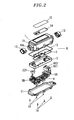
- Fig. 2 is an exploded perspective view showing the power feeding control apparatus A of the present embodiment.
- the power feeding control apparatus A includes a housing (main body housing part) 1 of elongated rectangular solid shape.
- the housing 1 includes a body 10 formed into a box-like shape with an open rear surface (lower surface in Fig. 2 ) and made from a synthetic resin molding; and a flat rear cover 11 provided to close the opening of the body 10 and made from a synthetic resin molding.
- the body 10 and the rear cover 11 are combined together by using fixing screws 16.
- Cable insertion holes 10a through which to insert cables PC and CC are formed in the vertical opposite end portions of the body 10 (Only the lower one of the cable insertion holes 10a is shown in Fig. 2 ).
- Caps 12 are attached to the vertical opposite end portions of the body 10 after the cables PC and CC have been inserted into the cable insertion holes 10a (see Figs. 3A to 3D ).
- the caps 12 are attached so that they can cover gaskets (not shown) made of a pliant material, e.g., ethylene propylene rubber. The gaskets hold the cables PC and CC in place and provide waterproof sealing of the housing 1.
- An 0-ring 13 is arranged between the body 10 and the rear cover 11 to seal the gap between the body 10 and the rear cover 11.
- a power supply PCB printed circuit board 4 mounted with circuit components (e.g., transformers, capacitors and the like) making up the voltage detection circuit 23 and the power supply circuit 24; a control PCB 2 mounted with circuit components making up the power availability determination circuit 20, the control circuit 21 and the leakage current detection circuit 22; the ZCT; the relays RY1 and RY2; terminal blocks 5A and 5B; and a bus bar block (power feeding line block) 3 making up the power feeding lines L and N, the ground line PE and the signal line L1, as shown in Fig. 2 .
- a power supply PCB printed circuit board 4 mounted with circuit components (e.g., transformers, capacitors and the like) making up the voltage detection circuit 23 and the power supply circuit 24
- a control PCB 2 mounted with circuit components making up the power availability determination circuit 20, the control circuit 21 and the leakage current detection circuit 22; the ZCT; the relays RY1 and RY2; terminal blocks 5A and 5B; and a bus bar block (power feeding line block) 3 making up
- a transparent cover 14 with a light transmitting property is arranged on the front surface of the housing 1.
- a label 15 is bonded to the front surface of the transparent cover 14.
- Mounted to the front surface (upper surface in Fig. 2 ) of the control PCB 2 are a power connection indication lamp to be turned on when the electric power is supplied from the external power source to the power feeding control apparatus A; an error indication lamp to be turned on when detecting an error (e.g., contact adhesion) in the relays RY1 and RY2 is detected; a test button for used in testing the power interruption operation to be performed at the occurrence of leakage current and a reset button for use in performing the reset operation making an open state of the relays RY1 and RY2.
- Letters and/or symbols indicative of the usage or functions of the corresponding lamps and buttons are provided in the labels 15. For example, other area than the letters and/or symbols in the label 15 are transparent to enable the user to see the lamps and manipulate the buttons.
- Fig. 6A is a perspective view showing the bus bar block 3 and Fig. 6B is a partial section view thereof.
- Fig. 7 is a front perspective view showing the bus bar block 3 and
- Fig. 8 is a layout diagram showing the bus bars of the bus bar block 3.
- the bus bar block 3 includes, as its main components, bus bars 31A and 31B making up the power feeding line L; bus bars 32A and 32B making up the power feeding line N; a bus bar 33A making up the ground line PE; a bus bar 34 making up the signal line L1; and a bus bar 37A making up the branch lines L2.
- Each of the bus bars 31A, 31B, 32A, 32B, 33A, 34 and 27A is made from a highly electrically conductive metal plate, e.g., copper plate.
- the bus bar block 3 is formed into a longitudinally elongated rectangular plate shape by an insertion-molding method in which the respective bus bars are used as insertion members (see Figs. 6A and 6B ).
- Fig. 5 is a schematic circuit diagram showing the bus bar block 3.
- the bus bar 31A provides electric connection between one end of the switch contact portion rp1 of the relay RY1 and the terminal block 5A, while the bus bar 31B provides the electric connection between the other end of the switch contact portion rp1 of the relay RY1 and the terminal block 5B.
- the bus bar 32A provides electric connection between one end of the switch contact portion rp2 of the relay RY2 and the terminal block 5A, while the bus bar 32B provides electric connection between the other end of the switch contact portion rp2 of the relay RY2 and the terminal block 5B.
- Reference characters L10 and L20 in Fig. 5 designate coils for driving the relays RY1 and RY2.
- a specified DC electric power (e.g., a DC 15V) is supplied from the power supply PCB 4 to the coils L10 and L20.
- the respective contact portions rp1 and rp2 are connected or disconnected by supplying or interrupting the DC electric power in response to the control signal outputted from the control PCB 2.
- a lead plate 31C, which is a part of the bus bar 31B, protruding upwards beyond a resin molding portion 30 and lead plates 33B, which are a part of the bus bar 33A, protruding upwards beyond the resin molding portion 30 are formed on the rear surface of the bus bar block 3 (the upper surface in Fig. 6A ).
- the lead plates 31C and 33B are electrically connected to the input terminals of the power supply circuit 24.
- a lead plate 37B, which is a part of the bus bar 37A, protruding upwards beyond the resin molding portion 30 is formed on the rear surface of the bus bar block 3.
- the lead plate 37B is electrically connected to the output terminal of the voltage detection circuit 23.
- a plurality of (seven in the example of Fig. 6A ) joint pins 36 for providing electric connection between the control PCB 2 and the power supply PCB 4 is formed to pass through the resin molding portion 30 in the front-rear direction.
- Boss portions 35 to which screws for fixing the power supply PCB 4 are to be threadedly coupled, are formed at three specified points on the rear surface of the bus bar block 3.
- a recess portion 30A for accommodating the ZCT is formed in the right lower portion of the bus bar block 3 in Fig. 6A .
- Boss portions 38, to which screws for fixing the control PCB 2 are to be threadedly coupled, are formed at four specified points on the front surface of the bus bar block 3 (the upper surface in Fig. 7 ).
- the power supply PCB 4 is fixed to the bus bar block 3 by screws in such a state that the front surface (the lower surface in Fig. 9 ), on which no circuit components are mounted, of the power supply PCB 4 is placed to face the rear surface (the upper surface in Fig. 9 ) of the bus bar block 3.
- the lead plates 31C, 33B and 37B and the joint pins 36 extend through the corresponding through-holes (not shown) formed in the power supply PCB 4 and are electrically and mechanically connected to the power supply PCB 4 by, e.g., soldering.
- the control PCB 2 is fixed to the front surface (the lower surface in Fig. 9 ) of the bus bar block 3 by screws.
- the bus bar block 3 is interposed between the power supply PCB 4 and the control PCB 2 in the present embodiment.
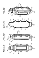
- Figs. 10 and 11A respectively show a perspective view and a side view showing the control PCB 2, the bus bar block 3 and the power supply PCB 4 fixed together.
- the assembly formed of the control PCB 2, the bus bar block 3 and the power supply PCB 4 is accommodated within the body 10 of the housing 1 in such a state that the upper side thereof in Fig. 11A faces toward the rear cover 11.
- the terminal block 5B to which the cable PC provided with the plug 60 can be removably connected, is arranged for providing electric connection between the cable PC and the power feeding lines L and N and the ground line PE.
- the terminal block 5B includes terminal plates 55, 56 and 57 electrically connected to the power feeding lines L and N and the ground line PE, respectively.
- Each of the terminal plates 55, 56 and 57 is made from a highly electrically conductive metal plate (e.g., a copper plate).
- the terminal plates 55 and 56 connected to the power feeding lines L and N are respectively provided with lead plates 55A and 56A integrally formed therewith and inserted into a central opening of the ZCT.
- the terminal plate 56 is provided with a lead plate 56B integrally formed therewith and electrically connected to the input terminal of the power supply circuit 24.
- a positioning portion 80 Molded in the central opening of the ZCT is a positioning portion 80 that has a pair of insertion holes 81 and 82 through which to insert the lead plates 55A and 56A and an insertion hole 82 through which to insert the bus bar 37C (see Fig. 6A ) making up a portion of the branch line L2.
- the ZCT is then placed within the recess portion 30A of the bus bar block 3. Thereafter, the positions of the terminal block 5B and the bus bar 37C are determined as illustrated in Figs. 12A and 12B when the lead plates 55A and 56A of the terminal plates 55 and 56 are inserted downward in Fig.
- the lead plate 55A is electrically connected at its tip end to the bus bar 31B by welding, soldering or the like.
- the lead plate 56A is electrically connected at its tip end to the bus bar 32B by welding, soldering or the like.
- the bus bar 37C is electrically connected at one end to the bus bar 37A by welding or the like and at the other end to the control PCB 2.
- the terminal block 5A to which the cable CC provided with the plug 60 can be removably connected, is arranged for providing electric connection between the cable CC and the power feeding lines L and N, the ground line PE and the signal line L1.
- the terminal block 5A includes terminal plates 51 to 54 electrically connected to the ground line PE, the power feeding lines L and N and the signal line L1, respectively.
- the terminal block 5A is fixed to the bus bar block 3.
- the relays RY1 and RY2 are arranged in the space between the terminal block 5A and the bus bar block 3 in the thickness direction of the bus bar block 3 (the up-down direction in Fig. 13A ).
- the terminal block 5A and the relays RY1 and RY2 are arranged in an overlapping relationship with each other along the thickness direction of the bus bar block 3.
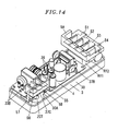
- Fig. 14 is a perspective view showing the control PCB 2, the bus bar block 3, the power supply PCB 4, the ZCT and the terminal blocks 5A and 5B, all of which are fixed together.
- electric power is supplied to the power supply PCB 4 through the lead plates 31C (see Fig. 9 ) and 56B (see Fig. 1 ).
- the bus bars 31A and 31B, the bus bars 32A and 32B in the bus bar block 3, the terminal plates 55 and 56 and the terminal plates 52 and 53 constitute the power feeding lines L and N.
- the operations of the power feeding control apparatus A and the electric vehicle B when starting to charge the battery 70 of the electric vehicle B will be described with reference to Fig. 4 .
- the plug 60 is connected to the socket 90 of the external power source with the connector 61 connected to the connector 72 of the electric vehicle B, an electric potential difference is generated between the power feeding lines L and N extending between the relays RY1 and RY2 and the power source (at the left side of the relays RY1 and RY2 in Fig. 4 ).
- the power availability determination circuit 20 detects the generation of the electric potential difference for a specified period of time, it determines that the plug 60 has been connected to the socket 90 and transmits a determination signal to the control circuit 21. The determination signal continues to be transmitted as long as the plug 60 remains connected to the socket 90.
- the control circuit 21 keeps the relays RY1 and RY2 in an off-state.
- the voltage detection circuit 23 detects the voltages developed in the power feeding lines L and N extending between the relays RY1 and RY2 and the electric vehicle B (at the right side of the relays RY1 and RY2 in Fig. 4 ).
- the control circuit 21 determines that the relays RY1 and RY2 are operating properly (the contact points of each of the contact portions rp1 and rp2 are not adhered to each other) and transmits a guide signal (of, e.g., 12V) to the electric vehicle B via the signal line L1.
- a guide signal of, e.g., 12V
- the charging control unit 75 of the electric vehicle B sends either a permission signal (of, e.g., 6V in voltage) or a standby signal (of, e.g., 9V) back to the control circuit 21 through the signal line L1 (the permission and the standby signals are "CPLT signals").
- the permission signal is sent if the battery 70 is in a rechargeable state and is permitted to be charged, but the standby signal is sent if the battery 70 is in a fully charged state and is not permitted to be charged.
- the guide signal sent from the control circuit 21 is returned back as it is (e.g., with the voltage of 12V unchanged) if the connector 61 is not connected to the connector 72 of the electric vehicle B. This enables the control circuit 21 to detect the disconnection of the connector 72.
- the control circuit 21 Upon receiving the permission signal sent from the electric vehicle B, the control circuit 21 turns on the relays RY1 and RY2 to start supplying electric power to the electric vehicle B and turns on the power connection indication lamp. If the standby signal is received from the electric vehicle B or if the guide signal is returned back as it is, the control circuit 21 stops charging the battery 70 with the relays RY1 and RY2 and the power connection indication lamp being turned off. If the voltage detection circuit 23 detects voltages when the relays RY1 and RY2 are kept turned off, the control circuit 21 determines that the relays RY1 and RY2 suffer from adhesion. In this case, the control circuit 21 turns on the error indication lamp and transmits an error signal (of, e.g., -12V) to the electric vehicle B through the signal line L1.
- an error signal of, e.g., -12V
- the charging control unit 75 of the electric vehicle B continues to transmit the permission signal to the control circuit 21 which in turn keeps the relays RY1 and RY2 turned on.
- the ZCT and the leakage current detection circuit 22 performs detection of leakage current by comparing the current I1 flowing from the power source toward the electric vehicle B through the power feeding line L or N with the sum of the current I2 flowing from the electric vehicle B toward the power source through the power feeding line L or N and the current I3 flowing from the electric vehicle B toward the power source through the branch lines L2.
- the current I1 is unbalanced with the sum of the currents I2 and I3, enabling the leakage current detection circuit 22 to detect the unbalanced current. If the unbalanced current is equal to or greater than a predetermined value, the leakage current detection circuit 22 determines that current leakage has occurred. In response thereto, the control circuit 21 turns off the relays RY1 and RY2, transmits an error signal to the electric vehicle B and turns on the error indication lamp. This makes it possible to prevent occurrence of electric shock accidents otherwise caused by the leakage current.
- the charging control unit 75 of the electric vehicle B Upon completing the charging operation of the battery 70, the charging control unit 75 of the electric vehicle B transmits the standby signal to the control circuit 21, which then turns off the relays RY1 and RY2.
- the voltage detection circuit 23 detects the voltage in the power feeding lines L and N to determine whether the contact portions rp1 and rp2 of the relays RY1 and RY2 suffer from adhesion problem. Further, the power connection indication lamp is turned off.
- insertion portions inserted into the central opening of the ZCT are formed of the lead plates 55A and 56A, so that it becomes easy to pass through the central opening of the ZCT, as compared with the case where such insertion portions are formed of the lead lines. Further, the positions of the lead plates 55A and 56A can be fixed by the positioning portions. This makes it easy to assemble the components of the power feeding control apparatus. Further, the lead plates 55A and 56A are integrally formed with the metal plates (the terminal plates 55 and 56) constituting the power feeding lines L and N. This eliminates the need to provide the lead plates to be inserted into the central opening separately from the metal plates, so that the number of circuit components can be reduced. Further, it is possible to reduce the time required in welding the lead plates to the metal plates, which makes it easy to manufacture the power feeding control apparatus A.
- the terminal block 5B and the ZCT are arranged in an overlapping relationship, it is possible to fit the terminal block 5B and the ZCT in a compact manner, which assists in reducing the size of the housing 1.
- the relays RY1 and RY2 are arranged in an overlapping relationship with the terminal block 5A, it is possible to fit the relays RY1 and RY2 in a compact manner, which assists in reducing the size of the housing 1.
- the lead plates 55A and 56A which are integrally formed with the terminal plates 55 and 56 of the terminal block 5B, are inserted into the central opening of the ZCT.
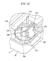
- a lead plate 31D formed by bending the tip end portion of the bus bar 31B and a lead plate 32D formed by bending the tip end portion of the bus bar 32B as illustrated in Fig. 15 can be inserted into the central opening of the ZCT.
- the positioning portions 80 is provided in the central opening of the ZCT, which makes it possible to fix the positions of the lead plates 31D and 32D.
- the tip end portions of the lead plates 31D and 32D are electrically connected to the terminal plates 55 and 56 by welding or the like.
- the power supply PCB 4 may be fixed to the bus bar block 3 such that the component mounting surface of the power supply PCB 4 faces toward the bus bar block 3 as shown in Fig. 11B . In this case, however, a dead space is generated as illustrated in Fig. 10B . This is because the components mounted to the power supply PCB 4 differ in height from one another. Further, the connection distance between the control PCB 2 and the power supply PCB 4 is increased.
Landscapes
- Engineering & Computer Science (AREA)
- Power Engineering (AREA)
- Transportation (AREA)
- Mechanical Engineering (AREA)
- Life Sciences & Earth Sciences (AREA)
- Sustainable Development (AREA)
- Sustainable Energy (AREA)
- Electric Propulsion And Braking For Vehicles (AREA)
- Charge And Discharge Circuits For Batteries Or The Like (AREA)
- Secondary Cells (AREA)
- Emergency Protection Circuit Devices (AREA)
Abstract
Description
- The present invention relates to a power feeding control apparatus.
- Conventionally, there is known a power feeding control apparatus for supplying electric power from an external power source to a battery provided in an electric vehicle such as a plug-in hybrid car or a battery-powered car (see, e.g., Japanese Patent Application Publication No.
2009-33789 Figs. 1 through 4 ). The power feeding control apparatus includes a zero current transformer, through which power feeding lines extend, for detecting leakage current in the electric vehicle. The zero current transformer detects the leakage current based on unbalanced currents flowing through the power feeding lines to prevent occurrence of electric shock accidents. - In the power feeding control apparatus described above, lead lines constitute the power feeding lines extending through the zero current transformer. This makes it difficult to assemble the power feeding control apparatus since the lead lines may be bent while passing through a central opening of the zero current transformer.
- In view of the above, the present invention provides a power feeding control apparatus capable of improving the ease of assembly.
- In accordance with an embodiment of the present invention, there is provided a power feeding control apparatus for controlling electric power supplied from an external power source to an electric vehicle provided with a battery and a charging circuit for charging the battery, including: power feeding lines provided to supply the electric power from the external power source to the electric vehicle therethrough; a relay unit arranged on the power feeding lines to open and close the power feeding lines; a control circuit for controlling the relay unit; a leakage current detection circuit for detecting leakage current in the electric vehicle; a power supply circuit supplied with the electric power through the power feeding lines to generate a control electric power; a housing for accommodating at least the power feeding lines, the relay unit, the control circuit, the leakage current detection circuit and the power supply circuit; a power source side connector to be removably connected to a socket of the external power source; and a vehicle side connector to be removably connected to a power receiving connector of the electric vehicle.
- Further, the leakage current detection circuit includes a zero current transformer through which the power feeding lines extend and is configured to detect leakage current based on unbalanced currents flowing through the power feeding lines. Lead plates constitute a part of the power feeding lines and the lead plates pass through a central opening of the zero current transformer. The zero current transformer includes a positioning member molded within the central opening to fix the positions of the lead plates.
- In this configuration, insertion portions inserted into the central opening of the zero current transformer are formed of the lead plates, so that it becomes easy to pass through the central opening of the zero current transformer, as compared with the case where such insertion portions are formed of the lead lines. Further, the positions of the lead plates can be fixed by the positioning portions. This makes it easy to assemble the components of the power feeding control apparatus.
- Further, the apparatus described above may further include a power feeding line block provided separately from a board on which the power supply circuit is mounted and a board on which the control circuit is mounted and having metal plates constituting the power feeding lines. The metal plates may be insertion-molded in the power feeding line block and the lead plates may be formed by having the metal plates, which are covered by a resin molding portion, partially protrude outwards beyond the resin molding portion.
- In this configuration, the lead plates are integrally formed with the metal plates constituting the power feeding lines. This eliminates the need to provide the lead plates separately from the metal plates, so that the number of circuit components can be reduced. Further, it is possible to reduce the time required in welding the lead plates to the metal plates, which makes it easy to manufacture the power feeding control apparatus.
- Further, the apparatus described above may further include a terminal block, to which a power source side cable is removably connected, for providing electric connection between the power source side cable and the power feeding lines. The terminal block may include terminal plates constitute the power feeding lines, and the lead plates may be formed from parts of the terminal plates.
- In this configuration, since the terminal block and the zero current transformer are arranged in an overlapping relationship, it is possible to fit the terminal block and the zero current transformer in a compact manner, which assists in reducing the size of the housing.
- Further, the apparatus described above may further include an additional terminal block, to which a vehicle side cable is removably connected, for providing electric connection between the vehicle side cable and the power feeding lines. The relay unit may be arranged on the power feeding lines in an overlapping relationship with the additional terminal block, and the additional terminal block may be connected to the power feeding lines of the vehicle side, the power feeding lines being electrically connected to one end of contact portion of the relay unit.
- In this configuration, there is a need to provide the relay unit at the side of the power feeding control apparatus closer to the electric vehicle so that the control circuit can operate even if the relay unit is in an off-state. Since the relay unit is arranged in an overlapping relationship with the additional terminal block, it is possible to fit the relay unit in a compact manner, which assists in reducing the size of the housing.
- The objects and features of the present invention will become apparent from the following description of embodiments given in conjunction with the accompanying drawings, in which:
-
Fig. 1 is a view for explaining the order of fixing the zero current transformer and the power source side terminal block to the bus bar block of the power feeding control apparatus in accordance with an embodiment of the present invention; -
Fig. 2 is an exploded perspective view showing a power feeding control apparatus in accordance with an embodiment of the present invention; -
Figs. 3A to 3D respectively show a front, a right side, a rear and a perspective view of the power feeding control apparatus; -
Fig. 4 is a schematic diagram showing a circuit employed in the power feeding control apparatus; -
Fig. 5 is a schematic circuit diagram showing a bus bar block employed in the power feeding control apparatus; -
Figs. 6A and 6B respectively show a perspective and a partial section view of the bus bar block employed in the power feeding control apparatus; -
Fig. 7 is a front perspective view showing the bus bar block employed in the power feeding control apparatus; -
Fig. 8 is a layout diagram showing the bus bars of the bus bar block employed in the power feeding control apparatus; -
Fig. 9 is a view for explaining the order of fixing the power supply PCB, the bus bar block and the control PCB employed in the power feeding control apparatus; -
Fig. 10 is a perspective view showing the power supply PCB, the bus bar block and the control PCB of the power feeding control apparatus fixed together; -
Fig. 11A is a side section view showing the power supply PCB, the bus bar block and the control PCB of the power feeding control apparatus fixed together, andFig. 11B is a side section view showing another examples in which the power supply PCB, the bus bar block and the control PCB are differently fixed together; -
Figs. 12A and 12B respectively show a side section and a perspective section view of the power feeding control apparatus in a state where the zero current transformer and the power source side terminal block are fixed to the bus bar block; -
Figs. 13A and 13B . respectively show a side and a perspective view of the power feeding control apparatus in a state where the relay and the vehicle side terminal block are fixed to the bus bar block; -
Fig. 14 is a perspective view showing the power supply PCB, the bus bar block, the control PCB and the terminal blocks of the power feeding control apparatus fixed together; and -
Fig. 15 is a perspective view illustrating an example in which parts of the bus bars constitute insertion portions inserted into the central opening of the zero current transformer. - An embodiment of a power feeding control apparatus in accordance with the present invention will be described with reference to the accompanying drawings which form a part hereof.
- As shown in
Fig. 4 , the power feeding control apparatus A of the present embodiment is connected to aplug 60 removably connected to apower outlet socket 90 supplying the electric power of an external power source, e.g., a commercial AC power source, and a connector 61 connected to an electric vehicle B through cables PC and CC, respectively. The power feeding control apparatus A controls the electric power supplied from the external power source to the electric vehicle B. The power feeding control apparatus A is used to supply or interrupt the electric power supplied to a charging circuit for charging abattery 70 provided in the electric vehicle B such as a battery-powered car or a plug-in hybrid car. Unless otherwise specifically mentioned in the following description, the up-down and left-right directions will be defined based onFig. 3A and the left-right direction inFig. 3B will be referred to as front-rear direction. However, these directions are defined merely for the sake of convenience in description and, therefore, may not coincide with the directions when the power feeding control apparatus A is actually used. The solid line arrows indicated inFig. 4 show the current flowing directions. However, the current flowing directions are changed alternately over time because the current flowing through the power feeding lines L and N is an alternating current. -
Fig. 4 is a schematic circuit diagram of the power feeding control apparatus A of the present embodiment and the electric vehicle B. - The electric vehicle B includes a
battery 70 composed of, e.g., lithium ion cells and provided to supply electric power to a motor (not shown) serving as a drive power source; abattery charger 71 for charging thebattery 70 with the DC power converted from the AC power which is supplied from the external commercial AC power source through the power feeding control apparatus A; aconnector 72 for connecting thebattery charger 71 to the power feeding control apparatus A; arelay 73 arranged in the charging path extending from thebattery charger 71 to thebattery 70; adetection unit 74 for detecting the AC power supplied to thebattery charger 71; and a chargingcontrol unit 75 for on-off controlling therelay 73 based on the detection result of thedetection unit 74. When the AC power is detected by thedetection unit 74, the chargingcontrol unit 75 turns on (or closes) therelay 73 so that thebattery charger 71 can charge thebattery 70. When the AC power is not detected by thedetection unit 74, the chargingcontrol unit 75 turns off (or opens) therelay 73 so that thebattery charger 71 can stop charging thebattery 70. - The power feeding control apparatus A includes the plug having a ground terminal (i.e., a power source side connector part) 60 removably connected to the
power outlet socket 90 of the external power source such as a commercial AC power source or the like; the connector (i.e., a vehicle side connector part) 61 connected to theconnector 72 of the electric vehicle B; and power feeding lines L and N and a ground line PE arranged between theplug 60 and the connector 61. - In addition to the power feeding lines L and N and the ground line PE, a signal line L1 for sending and receiving signals to and from the charging
control unit 75 of the electric vehicle B therethrough is connected to the connector 61. Normally open relays RY1 and RY2 are arranged in the power feeding lines L and N, respectively. Branch lines L2 are branched from the power feeding lines L and N between the relays RY1 and RY2 and the connector 61. The power feeding lines L and N pass through a zero current transformer (ZCT) between the relays RY1 and RY2 and theplug 60. - The signal line L1 is used for the electric vehicle B to transmit a state notifying signal (a so-called "CPLT signal") therethrough. Based on the state notifying signal, the power feeding control apparatus A can determine whether the electric vehicle B is in a disconnected state (a state in which the electric vehicle is not connected to the power feeding control apparatus), a charging standby state (a state in which the power feeding to the electric vehicle is stopped), a charging-permitted state (a state in which the electric power is being supplied to the electric vehicle) or a state in which the electric power is not usable.
- The power feeding control apparatus A further includes a power
availability determination circuit 20 connected to the power feeding lines L and N between the ZCT and theplug 60; acontrol circuit 21 connected to the electric vehicle B through the signal line L1 for on-off controlling the relays RY1 and RY2 in response to the state notifying signal (CPLT signal) transmitted from the electric vehicle B through the signal line L1; a leakagecurrent detection circuit 22 for detecting leakage current by having the ZCT detect the unbalanced current flowing through the power feeding lines L and N and for causing thecontrol circuit 21 to turn off the relays RY1 and RY2 when the leakage current is detected; avoltage detection circuit 23 arranged on the branch lines L2 that detects the voltages of the power feeding lines L and N between the relays RY1 and RY2 and the connector 61 from the currents flowing through the branch lines L2; and a power supply circuit 24 for supplying a control electric power to thecircuits 20 to 23. - The branch lines L2 are branched from the power feeding lines L and N at branch points thereof between the relays RY1 and RY2 and the electric vehicle B and opposite end portions of the branch lines L2 (which are merged into a single branch line L2 in this example) away from the branch points are grounded. The branch lines L2 are inserted into the ZCT in such a direction that the branch points where the branch lines L2 are branched from the power feeding lines L and N are positioned at the electric vehicle B side while the grounded end of the branch lines L2 are positioned at the power source side. Thus, an electric current 13 flows through the part of the branch lines L2 inserted into ZCT in the same direction as the flowing direction of an electric current 12 returned from the electric vehicle B to the power source through the power feeding lines L or N.
-
Fig. 2 is an exploded perspective view showing the power feeding control apparatus A of the present embodiment. The power feeding control apparatus A includes a housing (main body housing part) 1 of elongated rectangular solid shape. Thehousing 1 includes abody 10 formed into a box-like shape with an open rear surface (lower surface inFig. 2 ) and made from a synthetic resin molding; and a flatrear cover 11 provided to close the opening of thebody 10 and made from a synthetic resin molding. Thebody 10 and therear cover 11 are combined together by using fixing screws 16. -
Cable insertion holes 10a through which to insert cables PC and CC are formed in the vertical opposite end portions of the body 10 (Only the lower one of thecable insertion holes 10a is shown inFig. 2 ).Caps 12 are attached to the vertical opposite end portions of thebody 10 after the cables PC and CC have been inserted into thecable insertion holes 10a (seeFigs. 3A to 3D ). Thecaps 12 are attached so that they can cover gaskets (not shown) made of a pliant material, e.g., ethylene propylene rubber. The gaskets hold the cables PC and CC in place and provide waterproof sealing of thehousing 1. An 0-ring 13 is arranged between thebody 10 and therear cover 11 to seal the gap between thebody 10 and therear cover 11. - Accommodated within the
housing 1 are: a power supply PCB (printed circuit board) 4 mounted with circuit components (e.g., transformers, capacitors and the like) making up thevoltage detection circuit 23 and the power supply circuit 24; acontrol PCB 2 mounted with circuit components making up the poweravailability determination circuit 20, thecontrol circuit 21 and the leakagecurrent detection circuit 22; the ZCT; the relays RY1 and RY2;terminal blocks Fig. 2 . - A
transparent cover 14 with a light transmitting property is arranged on the front surface of thehousing 1. Alabel 15 is bonded to the front surface of thetransparent cover 14. Mounted to the front surface (upper surface inFig. 2 ) of thecontrol PCB 2 are a power connection indication lamp to be turned on when the electric power is supplied from the external power source to the power feeding control apparatus A; an error indication lamp to be turned on when detecting an error (e.g., contact adhesion) in the relays RY1 and RY2 is detected; a test button for used in testing the power interruption operation to be performed at the occurrence of leakage current and a reset button for use in performing the reset operation making an open state of the relays RY1 and RY2. Letters and/or symbols indicative of the usage or functions of the corresponding lamps and buttons are provided in thelabels 15. For example, other area than the letters and/or symbols in thelabel 15 are transparent to enable the user to see the lamps and manipulate the buttons. -
Fig. 6A is a perspective view showing thebus bar block 3 andFig. 6B is a partial section view thereof.Fig. 7 is a front perspective view showing thebus bar block 3 andFig. 8 is a layout diagram showing the bus bars of thebus bar block 3. - As shown in
Fig. 8 , thebus bar block 3 includes, as its main components,bus bars bus bars bus bar 33A making up the ground line PE; abus bar 34 making up the signal line L1; and abus bar 37A making up the branch lines L2. Each of the bus bars 31A, 31B, 32A, 32B, 33A, 34 and 27A is made from a highly electrically conductive metal plate, e.g., copper plate. Thebus bar block 3 is formed into a longitudinally elongated rectangular plate shape by an insertion-molding method in which the respective bus bars are used as insertion members (seeFigs. 6A and 6B ). -
Fig. 5 is a schematic circuit diagram showing thebus bar block 3. Thebus bar 31A provides electric connection between one end of the switch contact portion rp1 of the relay RY1 and theterminal block 5A, while thebus bar 31B provides the electric connection between the other end of the switch contact portion rp1 of the relay RY1 and theterminal block 5B. Thebus bar 32A provides electric connection between one end of the switch contact portion rp2 of the relay RY2 and theterminal block 5A, while thebus bar 32B provides electric connection between the other end of the switch contact portion rp2 of the relay RY2 and theterminal block 5B. - Therefore, when the relays RY1 and RY2 are turned on (i.e., closed), the
bus bars bus bars Fig. 5 designate coils for driving the relays RY1 and RY2. A specified DC electric power (e.g., aDC 15V) is supplied from thepower supply PCB 4 to the coils L10 and L20. The respective contact portions rp1 and rp2 are connected or disconnected by supplying or interrupting the DC electric power in response to the control signal outputted from thecontrol PCB 2. - A
lead plate 31C, which is a part of thebus bar 31B, protruding upwards beyond aresin molding portion 30 andlead plates 33B, which are a part of thebus bar 33A, protruding upwards beyond theresin molding portion 30 are formed on the rear surface of the bus bar block 3 (the upper surface inFig. 6A ). Thelead plates lead plate 37B, which is a part of thebus bar 37A, protruding upwards beyond theresin molding portion 30 is formed on the rear surface of thebus bar block 3. Thelead plate 37B is electrically connected to the output terminal of thevoltage detection circuit 23. - In addition, a plurality of (seven in the example of
Fig. 6A )joint pins 36 for providing electric connection between thecontrol PCB 2 and thepower supply PCB 4 is formed to pass through theresin molding portion 30 in the front-rear direction.Boss portions 35, to which screws for fixing thepower supply PCB 4 are to be threadedly coupled, are formed at three specified points on the rear surface of thebus bar block 3. Arecess portion 30A for accommodating the ZCT is formed in the right lower portion of thebus bar block 3 inFig. 6A .Boss portions 38, to which screws for fixing thecontrol PCB 2 are to be threadedly coupled, are formed at four specified points on the front surface of the bus bar block 3 (the upper surface inFig. 7 ). - Next, the order of assembling the
control PCB 2, thebus bar block 3 and thepower supply PCB 4 will be described with reference toFigs. 9 through 11 . - Referring to
Fig. 9 , circuit components making up thevoltage detection circuit 23 and the power supply circuit 24, e.g., transformers, capacitors and the like, are mounted on the rear surface (the upper surface inFig. 9 ) of thepower supply PCB 4. Thepower supply PCB 4 is fixed to thebus bar block 3 by screws in such a state that the front surface (the lower surface inFig. 9 ), on which no circuit components are mounted, of thepower supply PCB 4 is placed to face the rear surface (the upper surface inFig. 9 ) of thebus bar block 3. Thelead plates joint pins 36 extend through the corresponding through-holes (not shown) formed in thepower supply PCB 4 and are electrically and mechanically connected to thepower supply PCB 4 by, e.g., soldering. - The
control PCB 2 is fixed to the front surface (the lower surface inFig. 9 ) of thebus bar block 3 by screws. In other words, thebus bar block 3 is interposed between thepower supply PCB 4 and thecontrol PCB 2 in the present embodiment.Figs. 10 and11A respectively show a perspective view and a side view showing thecontrol PCB 2, thebus bar block 3 and thepower supply PCB 4 fixed together. The assembly formed of thecontrol PCB 2, thebus bar block 3 and thepower supply PCB 4 is accommodated within thebody 10 of thehousing 1 in such a state that the upper side thereof inFig. 11A faces toward therear cover 11. - In the present embodiment, as shown in
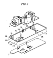
Fig. 1 , theterminal block 5B, to which the cable PC provided with theplug 60 can be removably connected, is arranged for providing electric connection between the cable PC and the power feeding lines L and N and the ground line PE. Theterminal block 5B includesterminal plates terminal plates terminal plates lead plates terminal plate 56 is provided with alead plate 56B integrally formed therewith and electrically connected to the input terminal of the power supply circuit 24. - Molded in the central opening of the ZCT is a
positioning portion 80 that has a pair of insertion holes 81 and 82 through which to insert thelead plates insertion hole 82 through which to insert thebus bar 37C (seeFig. 6A ) making up a portion of the branch line L2. The ZCT is then placed within therecess portion 30A of thebus bar block 3. Thereafter, the positions of theterminal block 5B and thebus bar 37C are determined as illustrated inFigs. 12A and 12B when thelead plates terminal plates Fig. 1 into the corresponding insertion holes 81 to pass therethrough, and the tip end portion of thebus bar 37C is inserted into theinsertion hole 82 to pass therethrough. Thelead plate 55A is electrically connected at its tip end to thebus bar 31B by welding, soldering or the like. Similarly, thelead plate 56A is electrically connected at its tip end to thebus bar 32B by welding, soldering or the like. Moreover, thebus bar 37C is electrically connected at one end to thebus bar 37A by welding or the like and at the other end to thecontrol PCB 2. - In the present embodiment, as shown in
Figs. 13A and 13B , theterminal block 5A, to which the cable CC provided with theplug 60 can be removably connected, is arranged for providing electric connection between the cable CC and the power feeding lines L and N, the ground line PE and the signal line L1. Theterminal block 5A includesterminal plates 51 to 54 electrically connected to the ground line PE, the power feeding lines L and N and the signal line L1, respectively. - The
terminal block 5A is fixed to thebus bar block 3. In the present embodiment, the relays RY1 and RY2 are arranged in the space between theterminal block 5A and thebus bar block 3 in the thickness direction of the bus bar block 3 (the up-down direction inFig. 13A ). In other words, theterminal block 5A and the relays RY1 and RY2 are arranged in an overlapping relationship with each other along the thickness direction of thebus bar block 3.Fig. 14 is a perspective view showing thecontrol PCB 2, thebus bar block 3, thepower supply PCB 4, the ZCT and the terminal blocks 5A and 5B, all of which are fixed together. In the present embodiment, electric power is supplied to thepower supply PCB 4 through thelead plates 31C (seeFig. 9 ) and 56B (seeFig. 1 ). Further, thebus bars bus bars bus bar block 3, theterminal plates terminal plates - Next, the operations of the power feeding control apparatus A and the electric vehicle B when starting to charge the
battery 70 of the electric vehicle B will be described with reference toFig. 4 . If theplug 60 is connected to thesocket 90 of the external power source with the connector 61 connected to theconnector 72 of the electric vehicle B, an electric potential difference is generated between the power feeding lines L and N extending between the relays RY1 and RY2 and the power source (at the left side of the relays RY1 and RY2 inFig. 4 ). If the poweravailability determination circuit 20 detects the generation of the electric potential difference for a specified period of time, it determines that theplug 60 has been connected to thesocket 90 and transmits a determination signal to thecontrol circuit 21. The determination signal continues to be transmitted as long as theplug 60 remains connected to thesocket 90. - Responsive to the determination signal sent from the power
availability determination circuit 20, thecontrol circuit 21 keeps the relays RY1 and RY2 in an off-state. After the lapse of a specified time until the respective circuits become stable (e.g., 75 ms, which is taken until the respective circuits are sufficiently discharged after the electric current flows through the circuits), thevoltage detection circuit 23 detects the voltages developed in the power feeding lines L and N extending between the relays RY1 and RY2 and the electric vehicle B (at the right side of the relays RY1 and RY2 inFig. 4 ). If thevoltage detection circuit 23 fails to detect the voltages when the relays RY1 and RY2 are in the off-state, thecontrol circuit 21 determines that the relays RY1 and RY2 are operating properly (the contact points of each of the contact portions rp1 and rp2 are not adhered to each other) and transmits a guide signal (of, e.g., 12V) to the electric vehicle B via the signal line L1. - Responsive to the guide signal, the charging
control unit 75 of the electric vehicle B sends either a permission signal (of, e.g., 6V in voltage) or a standby signal (of, e.g., 9V) back to thecontrol circuit 21 through the signal line L1 (the permission and the standby signals are "CPLT signals"). The permission signal is sent if thebattery 70 is in a rechargeable state and is permitted to be charged, but the standby signal is sent if thebattery 70 is in a fully charged state and is not permitted to be charged. The guide signal sent from thecontrol circuit 21 is returned back as it is (e.g., with the voltage of 12V unchanged) if the connector 61 is not connected to theconnector 72 of the electric vehicle B. This enables thecontrol circuit 21 to detect the disconnection of theconnector 72. - Upon receiving the permission signal sent from the electric vehicle B, the
control circuit 21 turns on the relays RY1 and RY2 to start supplying electric power to the electric vehicle B and turns on the power connection indication lamp. If the standby signal is received from the electric vehicle B or if the guide signal is returned back as it is, thecontrol circuit 21 stops charging thebattery 70 with the relays RY1 and RY2 and the power connection indication lamp being turned off. If thevoltage detection circuit 23 detects voltages when the relays RY1 and RY2 are kept turned off, thecontrol circuit 21 determines that the relays RY1 and RY2 suffer from adhesion. In this case, thecontrol circuit 21 turns on the error indication lamp and transmits an error signal (of, e.g., -12V) to the electric vehicle B through the signal line L1. - While the
battery 70 of the electric vehicle B is charged, the chargingcontrol unit 75 of the electric vehicle B continues to transmit the permission signal to thecontrol circuit 21 which in turn keeps the relays RY1 and RY2 turned on. In the charging process, the ZCT and the leakagecurrent detection circuit 22 performs detection of leakage current by comparing the current I1 flowing from the power source toward the electric vehicle B through the power feeding line L or N with the sum of the current I2 flowing from the electric vehicle B toward the power source through the power feeding line L or N and the current I3 flowing from the electric vehicle B toward the power source through the branch lines L2. In the event that current leakage occurs in the electric vehicle B, the current I1 is unbalanced with the sum of the currents I2 and I3, enabling the leakagecurrent detection circuit 22 to detect the unbalanced current. If the unbalanced current is equal to or greater than a predetermined value, the leakagecurrent detection circuit 22 determines that current leakage has occurred. In response thereto, thecontrol circuit 21 turns off the relays RY1 and RY2, transmits an error signal to the electric vehicle B and turns on the error indication lamp. This makes it possible to prevent occurrence of electric shock accidents otherwise caused by the leakage current. - Upon completing the charging operation of the
battery 70, the chargingcontrol unit 75 of the electric vehicle B transmits the standby signal to thecontrol circuit 21, which then turns off the relays RY1 and RY2. Thevoltage detection circuit 23 then detects the voltage in the power feeding lines L and N to determine whether the contact portions rp1 and rp2 of the relays RY1 and RY2 suffer from adhesion problem. Further, the power connection indication lamp is turned off. - In the present embodiment, insertion portions inserted into the central opening of the ZCT are formed of the
lead plates lead plates lead plates terminal plates 55 and 56) constituting the power feeding lines L and N. This eliminates the need to provide the lead plates to be inserted into the central opening separately from the metal plates, so that the number of circuit components can be reduced. Further, it is possible to reduce the time required in welding the lead plates to the metal plates, which makes it easy to manufacture the power feeding control apparatus A. - Since the
terminal block 5B and the ZCT are arranged in an overlapping relationship, it is possible to fit theterminal block 5B and the ZCT in a compact manner, which assists in reducing the size of thehousing 1. There is a need to provide the relays RY1 and RY2 at the side of the power feeding control apparatus A closer to the electric vehicle B so that thecontrol circuit 21 can operate even if the relays RY1 and RY2 are in an off-state. Since the relays RY1 and RY2 are arranged in an overlapping relationship with theterminal block 5A, it is possible to fit the relays RY1 and RY2 in a compact manner, which assists in reducing the size of thehousing 1. - In the embodiment described above, the
lead plates terminal plates terminal block 5B, are inserted into the central opening of the ZCT. As an alternative example, alead plate 31D formed by bending the tip end portion of thebus bar 31B and alead plate 32D formed by bending the tip end portion of thebus bar 32B as illustrated inFig. 15 can be inserted into the central opening of the ZCT. In this case also, there is no need to separately provide lead plates to be inserted into the central opening of the ZCT. This makes it easy to manufacture the power feeding control apparatus A. As in the embodiment set forth above, thepositioning portions 80 is provided in the central opening of the ZCT, which makes it possible to fix the positions of thelead plates lead plates terminal plates - The
power supply PCB 4 may be fixed to thebus bar block 3 such that the component mounting surface of thepower supply PCB 4 faces toward thebus bar block 3 as shown inFig. 11B . In this case, however, a dead space is generated as illustrated inFig. 10B . This is because the components mounted to thepower supply PCB 4 differ in height from one another. Further, the connection distance between thecontrol PCB 2 and thepower supply PCB 4 is increased. - While the invention has been shown and described with respect to the embodiments, it will be understood by those skilled in the art that various changes and modification may be made without departing from the scope of the invention as defined in the following claims.
Claims (4)
- A power feeding control apparatus for controlling electric power supplied from an external power source to an electric vehicle provided with a battery and a charging circuit for charging the battery, comprising:power feeding lines provided to supply the electric power from the external power source to the electric vehicle therethrough;a relay unit arranged on the power feeding lines to open and close the power feeding lines;a control circuit for controlling the relay unit;a leakage current detection circuit for detecting leakage current in the electric vehicle;a power supply circuit supplied with the electric power through the power feeding lines to generate a control electric power;a housing for accommodating at least the power feeding lines, the relay unit, the control circuit, the leakage current detection circuit and the power supply circuit;a power source side connector to be removably connected to a socket of the external power source; anda vehicle side connector to be removably connected to a power receiving connector of the electric vehicle,wherein the leakage current detection circuit includes a zero current transformer through which the power feeding lines extend and is configured to detect leakage current based on unbalanced currents flowing through the power feeding lines,wherein lead plates constitute a part of the power feeding lines,wherein the lead plates pass through a central opening of the zero current transformer, andwherein the zero current transformer includes a positioning member molded within the central opening to fix the positions of the lead plates.
- The apparatus of claim 1, further comprising a power feeding line block provided separately from a board on which the power supply circuit is mounted and a board on which the control circuit is mounted and having metal plates constituting the power feeding lines,
wherein the metal plates are insertion-molded in the power feeding line block, and
wherein the lead plates are formed by having the metal plates, which are covered by a resin molding portion, partially protrude outwards beyond the resin molding portion. - The apparatus of claim 1, further comprising a terminal block, to which a power source side cable is removably connected, for providing electric connection between the power source side cable and the power feeding lines,
wherein the terminal block includes terminal plates constitute the power feeding lines, and the lead plates are formed from parts of the terminal plates. - The apparatus of claim 2 or 3, further comprising an additional terminal block, to which a vehicle side cable is removably connected, for providing electric connection between the vehicle side cable and the power feeding lines,
wherein the relay unit is arranged on the power feeding lines in an overlapping relationship with the additional terminal block, and
wherein the additional terminal block is connected to the power feeding lines of the vehicle side, the power feeding lines being electrically connected to one end of contact portion of the relay unit.
Applications Claiming Priority (1)
| Application Number | Priority Date | Filing Date | Title |
|---|---|---|---|
| JP2009291461A JP5513875B2 (en) | 2009-12-22 | 2009-12-22 | Power supply control device |
Publications (3)
| Publication Number | Publication Date |
|---|---|
| EP2338722A2 true EP2338722A2 (en) | 2011-06-29 |
| EP2338722A3 EP2338722A3 (en) | 2016-10-05 |
| EP2338722B1 EP2338722B1 (en) | 2018-11-14 |
Family
ID=43881241
Family Applications (1)
| Application Number | Title | Priority Date | Filing Date |
|---|---|---|---|
| EP10015831.0A Active EP2338722B1 (en) | 2009-12-22 | 2010-12-20 | Power feeding control apparatus |
Country Status (5)
| Country | Link |
|---|---|
| US (1) | US9096139B2 (en) |
| EP (1) | EP2338722B1 (en) |
| JP (1) | JP5513875B2 (en) |
| CN (1) | CN102104243B (en) |
| AU (1) | AU2010257368B2 (en) |
Cited By (3)
| Publication number | Priority date | Publication date | Assignee | Title |
|---|---|---|---|---|
| WO2020167141A1 (en) * | 2019-02-15 | 2020-08-20 | Easee As | Terminal assembly for an electric vehicle charger, charger and method of manufacturing of both |
| NO20190387A1 (en) * | 2019-03-22 | 2020-09-23 | Easee As | Circuit board for an electric vehicle charging station |
| FR3127645A1 (en) * | 2021-09-27 | 2023-03-31 | Tyco Electronics France Sas | Substrate intended for contacting with at least one electrical pin of a charging socket |
Families Citing this family (11)
| Publication number | Priority date | Publication date | Assignee | Title |
|---|---|---|---|---|
| JP5578870B2 (en) * | 2010-02-03 | 2014-08-27 | 矢崎総業株式会社 | Busbar mounting body and vehicle room lamp equipped with the same |
| WO2013073034A1 (en) * | 2011-11-17 | 2013-05-23 | トヨタ自動車株式会社 | Vehicle and power supply system |
| CN103166172B (en) * | 2011-12-17 | 2017-06-20 | 富泰华工业(深圳)有限公司 | Leakage protection circuit, socket and electronic installation with leakage protection circuit |
| KR102025947B1 (en) * | 2012-12-27 | 2019-09-26 | 타이코에이엠피 주식회사 | Protection circuit module and battery module including the same |
| JP6123134B2 (en) * | 2013-03-28 | 2017-05-10 | パナソニックIpマネジメント株式会社 | Power supply control device |
| KR101587629B1 (en) * | 2014-09-12 | 2016-01-22 | 주식회사 경신 | In-cable control device |
| JP6224023B2 (en) * | 2015-03-27 | 2017-11-01 | 矢崎総業株式会社 | Electronic component unit and electrical junction box |
| KR101734683B1 (en) * | 2015-10-07 | 2017-05-11 | 현대자동차주식회사 | Power Distibuting Block Of Vehicle |
| USD835589S1 (en) * | 2017-11-15 | 2018-12-11 | Jiangyin Sinbon Electronics Co., Ltd. | Controller for controlling charging current |
| US11313917B2 (en) | 2020-05-13 | 2022-04-26 | Lear Corporation | Electric current sensor for detecting leakage current |
| CN113022345A (en) * | 2021-03-12 | 2021-06-25 | 西安领充创享新能源科技有限公司 | Alternating current charging assembly and alternating current charging equipment |
Citations (1)
| Publication number | Priority date | Publication date | Assignee | Title |
|---|---|---|---|---|
| JP2009033789A (en) | 2007-07-24 | 2009-02-12 | Panasonic Electric Works Co Ltd | Charging monitor |
Family Cites Families (13)
| Publication number | Priority date | Publication date | Assignee | Title |
|---|---|---|---|---|
| JPH0828182B2 (en) * | 1989-07-10 | 1996-03-21 | 富士電機株式会社 | Earth leakage circuit breaker |
| US6122155A (en) * | 1997-04-22 | 2000-09-19 | Tower Manufacturing Corporation | Mini appliance leakage current interrupter |
| JP3704885B2 (en) * | 1997-05-19 | 2005-10-12 | 富士電機機器制御株式会社 | Leakage current detection structure of earth leakage breaker |
| JPH1118282A (en) * | 1997-06-25 | 1999-01-22 | Matsushita Electric Works Ltd | Leak detector |
| JP2000217245A (en) * | 1999-01-22 | 2000-08-04 | Matsushita Electric Works Ltd | Ground-fault circuit breaker |
| JP2002217245A (en) | 2001-01-18 | 2002-08-02 | Hitachi Cable Ltd | Method of manufacturing tape carrier |
| JP2008153173A (en) | 2006-12-20 | 2008-07-03 | Gold King Kk | External electrode type fluorescent lamp |
| JP4894646B2 (en) * | 2007-06-15 | 2012-03-14 | トヨタ自動車株式会社 | Charging device and charging system |
| JP5015685B2 (en) | 2007-07-24 | 2012-08-29 | パナソニック株式会社 | Charge monitoring device |
| AU2008280932B8 (en) * | 2007-07-24 | 2011-02-24 | Panasonic Electric Works Co., Ltd. | Charging monitor |
| CN201134662Y (en) * | 2007-12-27 | 2008-10-15 | 余博贺 | Leakage detecting and protecting device |
| JP2009240053A (en) * | 2008-03-26 | 2009-10-15 | Panasonic Electric Works Co Ltd | Power supply controller |
| JP5834229B2 (en) * | 2009-12-22 | 2015-12-16 | パナソニックIpマネジメント株式会社 | Power supply control device |
-
2009
- 2009-12-22 JP JP2009291461A patent/JP5513875B2/en active Active
-
2010
- 2010-12-20 EP EP10015831.0A patent/EP2338722B1/en active Active
- 2010-12-21 CN CN201010613595XA patent/CN102104243B/en active Active
- 2010-12-22 AU AU2010257368A patent/AU2010257368B2/en not_active Ceased
- 2010-12-22 US US12/975,605 patent/US9096139B2/en active Active
Patent Citations (1)
| Publication number | Priority date | Publication date | Assignee | Title |
|---|---|---|---|---|
| JP2009033789A (en) | 2007-07-24 | 2009-02-12 | Panasonic Electric Works Co Ltd | Charging monitor |
Cited By (7)
| Publication number | Priority date | Publication date | Assignee | Title |
|---|---|---|---|---|
| WO2020167141A1 (en) * | 2019-02-15 | 2020-08-20 | Easee As | Terminal assembly for an electric vehicle charger, charger and method of manufacturing of both |
| US20220105818A1 (en) * | 2019-02-15 | 2022-04-07 | Easee As | Terminal assembly for an electric vehicle charger, charger and method of manufacturing of both |
| AU2020222942B2 (en) * | 2019-02-15 | 2022-09-29 | Easee As | Terminal assembly for an electric vehicle charger, charger and method of manufacturing of both |
| EP3924212A4 (en) * | 2019-02-15 | 2022-12-14 | Easee AS | Terminal assembly for an electric vehicle charger, charger and method of manufacturing of both |
| NO346763B1 (en) * | 2019-02-15 | 2022-12-19 | Easee As | Terminal assembly for an electric vehicle charger, charger and method of manufacturing of both |
| NO20190387A1 (en) * | 2019-03-22 | 2020-09-23 | Easee As | Circuit board for an electric vehicle charging station |
| FR3127645A1 (en) * | 2021-09-27 | 2023-03-31 | Tyco Electronics France Sas | Substrate intended for contacting with at least one electrical pin of a charging socket |
Also Published As
| Publication number | Publication date |
|---|---|
| CN102104243A (en) | 2011-06-22 |
| AU2010257368B2 (en) | 2013-08-01 |
| JP2011135654A (en) | 2011-07-07 |
| US9096139B2 (en) | 2015-08-04 |
| US20110148191A1 (en) | 2011-06-23 |
| EP2338722B1 (en) | 2018-11-14 |
| JP5513875B2 (en) | 2014-06-04 |
| CN102104243B (en) | 2013-12-11 |
| EP2338722A3 (en) | 2016-10-05 |
| AU2010257368A1 (en) | 2011-07-07 |
Similar Documents
| Publication | Publication Date | Title |
|---|---|---|
| EP2338722B1 (en) | Power feeding control apparatus | |
| US8421404B2 (en) | Power feeding control apparatus | |
| CN102074979B (en) | Feed control device | |
| CN104071020B (en) | Power supply control apparatus | |
| CN102656766B (en) | Vapour charger on automobile | |
| WO2012104703A1 (en) | Power feeding control device | |
| JP2013046477A (en) | Charger for electric vehicle | |
| CN101783520B (en) | Battery charger and detection structure for detecting mounted compact electric apparatus | |
| EP2783902B1 (en) | Power supply control device for charging an electric vehicle | |
| JP5796219B2 (en) | Power supply control device | |
| CN111284340B (en) | Charging device for electric vehicle | |
| JP5834186B2 (en) | Power supply control device | |
| CN107797053B (en) | Monitoring unit for monitoring circuit breaker and circuit breaker comprising same | |
| JP5707559B2 (en) | Power supply control device | |
| JP2014100056A (en) | Current supply control unit | |
| JP2014064463A (en) | Power supply control device |
Legal Events
| Date | Code | Title | Description |
|---|---|---|---|
| PUAI | Public reference made under article 153(3) epc to a published international application that has entered the european phase |
Free format text: ORIGINAL CODE: 0009012 |
|
| AK | Designated contracting states |
Kind code of ref document: A2 Designated state(s): AL AT BE BG CH CY CZ DE DK EE ES FI FR GB GR HR HU IE IS IT LI LT LU LV MC MK MT NL NO PL PT RO RS SE SI SK SM TR |
|
| AX | Request for extension of the european patent |
Extension state: BA ME |
|
| RAP1 | Party data changed (applicant data changed or rights of an application transferred) |
Owner name: PANASONIC CORPORATION |
|
| 17P | Request for examination filed |
Effective date: 20140331 |
|
| RBV | Designated contracting states (corrected) |
Designated state(s): AL AT BE BG CH CY CZ DE DK EE ES FI FR GB GR HR HU IE IS IT LI LT LU LV MC MK MT NL NO PL PT RO RS SE SI SK SM TR |
|
| RAP1 | Party data changed (applicant data changed or rights of an application transferred) |
Owner name: PANASONIC INTELLECTUAL PROPERTY MANAGEMENT CO., LT |
|
| PUAL | Search report despatched |
Free format text: ORIGINAL CODE: 0009013 |
|
| AK | Designated contracting states |
Kind code of ref document: A3 Designated state(s): AL AT BE BG CH CY CZ DE DK EE ES FI FR GB GR HR HU IE IS IT LI LT LU LV MC MK MT NL NO PL PT RO RS SE SI SK SM TR |
|
| AX | Request for extension of the european patent |
Extension state: BA ME |
|
| RIC1 | Information provided on ipc code assigned before grant |
Ipc: B60L 11/18 20060101AFI20160829BHEP Ipc: G01R 31/02 20060101ALI20160829BHEP Ipc: B60L 3/04 20060101ALI20160829BHEP Ipc: H01H 83/02 20060101ALI20160829BHEP Ipc: G01R 27/18 20060101ALI20160829BHEP Ipc: B60L 3/00 20060101ALI20160829BHEP |
|
| 17Q | First examination report despatched |
Effective date: 20171115 |
|
| GRAP | Despatch of communication of intention to grant a patent |
Free format text: ORIGINAL CODE: EPIDOSNIGR1 |
|
| INTG | Intention to grant announced |
Effective date: 20180525 |
|
| GRAS | Grant fee paid |
Free format text: ORIGINAL CODE: EPIDOSNIGR3 |
|
| GRAA | (expected) grant |
Free format text: ORIGINAL CODE: 0009210 |
|
| AK | Designated contracting states |
Kind code of ref document: B1 Designated state(s): AL AT BE BG CH CY CZ DE DK EE ES FI FR GB GR HR HU IE IS IT LI LT LU LV MC MK MT NL NO PL PT RO RS SE SI SK SM TR |
|
| REG | Reference to a national code |
Ref country code: GB Ref legal event code: FG4D |
|
| REG | Reference to a national code |
Ref country code: CH Ref legal event code: EP Ref country code: AT Ref legal event code: REF Ref document number: 1064389 Country of ref document: AT Kind code of ref document: T Effective date: 20181115 |
|
| REG | Reference to a national code |
Ref country code: DE Ref legal event code: R096 Ref document number: 602010055036 Country of ref document: DE |
|
| REG | Reference to a national code |
Ref country code: IE Ref legal event code: FG4D |
|
| REG | Reference to a national code |
Ref country code: DE Ref legal event code: R079 Ref document number: 602010055036 Country of ref document: DE Free format text: PREVIOUS MAIN CLASS: B60L0011180000 Ipc: B60L0050500000 |
|
| REG | Reference to a national code |
Ref country code: NL Ref legal event code: MP Effective date: 20181114 |
|
| REG | Reference to a national code |
Ref country code: LT Ref legal event code: MG4D |
|
| REG | Reference to a national code |
Ref country code: AT Ref legal event code: MK05 Ref document number: 1064389 Country of ref document: AT Kind code of ref document: T Effective date: 20181114 |
|
| PG25 | Lapsed in a contracting state [announced via postgrant information from national office to epo] |
Ref country code: FI Free format text: LAPSE BECAUSE OF FAILURE TO SUBMIT A TRANSLATION OF THE DESCRIPTION OR TO PAY THE FEE WITHIN THE PRESCRIBED TIME-LIMIT Effective date: 20181114 Ref country code: HR Free format text: LAPSE BECAUSE OF FAILURE TO SUBMIT A TRANSLATION OF THE DESCRIPTION OR TO PAY THE FEE WITHIN THE PRESCRIBED TIME-LIMIT Effective date: 20181114 Ref country code: LT Free format text: LAPSE BECAUSE OF FAILURE TO SUBMIT A TRANSLATION OF THE DESCRIPTION OR TO PAY THE FEE WITHIN THE PRESCRIBED TIME-LIMIT Effective date: 20181114 Ref country code: AT Free format text: LAPSE BECAUSE OF FAILURE TO SUBMIT A TRANSLATION OF THE DESCRIPTION OR TO PAY THE FEE WITHIN THE PRESCRIBED TIME-LIMIT Effective date: 20181114 Ref country code: NO Free format text: LAPSE BECAUSE OF FAILURE TO SUBMIT A TRANSLATION OF THE DESCRIPTION OR TO PAY THE FEE WITHIN THE PRESCRIBED TIME-LIMIT Effective date: 20190214 Ref country code: LV Free format text: LAPSE BECAUSE OF FAILURE TO SUBMIT A TRANSLATION OF THE DESCRIPTION OR TO PAY THE FEE WITHIN THE PRESCRIBED TIME-LIMIT Effective date: 20181114 Ref country code: IS Free format text: LAPSE BECAUSE OF FAILURE TO SUBMIT A TRANSLATION OF THE DESCRIPTION OR TO PAY THE FEE WITHIN THE PRESCRIBED TIME-LIMIT Effective date: 20190314 Ref country code: ES Free format text: LAPSE BECAUSE OF FAILURE TO SUBMIT A TRANSLATION OF THE DESCRIPTION OR TO PAY THE FEE WITHIN THE PRESCRIBED TIME-LIMIT Effective date: 20181114 Ref country code: BG Free format text: LAPSE BECAUSE OF FAILURE TO SUBMIT A TRANSLATION OF THE DESCRIPTION OR TO PAY THE FEE WITHIN THE PRESCRIBED TIME-LIMIT Effective date: 20190214 |
|
| PG25 | Lapsed in a contracting state [announced via postgrant information from national office to epo] |
Ref country code: AL Free format text: LAPSE BECAUSE OF FAILURE TO SUBMIT A TRANSLATION OF THE DESCRIPTION OR TO PAY THE FEE WITHIN THE PRESCRIBED TIME-LIMIT Effective date: 20181114 Ref country code: SE Free format text: LAPSE BECAUSE OF FAILURE TO SUBMIT A TRANSLATION OF THE DESCRIPTION OR TO PAY THE FEE WITHIN THE PRESCRIBED TIME-LIMIT Effective date: 20181114 Ref country code: PT Free format text: LAPSE BECAUSE OF FAILURE TO SUBMIT A TRANSLATION OF THE DESCRIPTION OR TO PAY THE FEE WITHIN THE PRESCRIBED TIME-LIMIT Effective date: 20190314 Ref country code: NL Free format text: LAPSE BECAUSE OF FAILURE TO SUBMIT A TRANSLATION OF THE DESCRIPTION OR TO PAY THE FEE WITHIN THE PRESCRIBED TIME-LIMIT Effective date: 20181114 Ref country code: GR Free format text: LAPSE BECAUSE OF FAILURE TO SUBMIT A TRANSLATION OF THE DESCRIPTION OR TO PAY THE FEE WITHIN THE PRESCRIBED TIME-LIMIT Effective date: 20190215 Ref country code: RS Free format text: LAPSE BECAUSE OF FAILURE TO SUBMIT A TRANSLATION OF THE DESCRIPTION OR TO PAY THE FEE WITHIN THE PRESCRIBED TIME-LIMIT Effective date: 20181114 |
|
| PG25 | Lapsed in a contracting state [announced via postgrant information from national office to epo] |
Ref country code: CZ Free format text: LAPSE BECAUSE OF FAILURE TO SUBMIT A TRANSLATION OF THE DESCRIPTION OR TO PAY THE FEE WITHIN THE PRESCRIBED TIME-LIMIT Effective date: 20181114 Ref country code: PL Free format text: LAPSE BECAUSE OF FAILURE TO SUBMIT A TRANSLATION OF THE DESCRIPTION OR TO PAY THE FEE WITHIN THE PRESCRIBED TIME-LIMIT Effective date: 20181114 Ref country code: IT Free format text: LAPSE BECAUSE OF FAILURE TO SUBMIT A TRANSLATION OF THE DESCRIPTION OR TO PAY THE FEE WITHIN THE PRESCRIBED TIME-LIMIT Effective date: 20181114 Ref country code: DK Free format text: LAPSE BECAUSE OF FAILURE TO SUBMIT A TRANSLATION OF THE DESCRIPTION OR TO PAY THE FEE WITHIN THE PRESCRIBED TIME-LIMIT Effective date: 20181114 |
|
| REG | Reference to a national code |
Ref country code: CH Ref legal event code: PL |
|
| REG | Reference to a national code |
Ref country code: DE Ref legal event code: R097 Ref document number: 602010055036 Country of ref document: DE |
|
| PG25 | Lapsed in a contracting state [announced via postgrant information from national office to epo] |
Ref country code: SM Free format text: LAPSE BECAUSE OF FAILURE TO SUBMIT A TRANSLATION OF THE DESCRIPTION OR TO PAY THE FEE WITHIN THE PRESCRIBED TIME-LIMIT Effective date: 20181114 Ref country code: EE Free format text: LAPSE BECAUSE OF FAILURE TO SUBMIT A TRANSLATION OF THE DESCRIPTION OR TO PAY THE FEE WITHIN THE PRESCRIBED TIME-LIMIT Effective date: 20181114 Ref country code: SK Free format text: LAPSE BECAUSE OF FAILURE TO SUBMIT A TRANSLATION OF THE DESCRIPTION OR TO PAY THE FEE WITHIN THE PRESCRIBED TIME-LIMIT Effective date: 20181114 Ref country code: MC Free format text: LAPSE BECAUSE OF FAILURE TO SUBMIT A TRANSLATION OF THE DESCRIPTION OR TO PAY THE FEE WITHIN THE PRESCRIBED TIME-LIMIT Effective date: 20181114 Ref country code: RO Free format text: LAPSE BECAUSE OF FAILURE TO SUBMIT A TRANSLATION OF THE DESCRIPTION OR TO PAY THE FEE WITHIN THE PRESCRIBED TIME-LIMIT Effective date: 20181114 Ref country code: LU Free format text: LAPSE BECAUSE OF NON-PAYMENT OF DUE FEES Effective date: 20181220 |
|
| REG | Reference to a national code |
Ref country code: IE Ref legal event code: MM4A |
|
| PLBE | No opposition filed within time limit |
Free format text: ORIGINAL CODE: 0009261 |
|
| STAA | Information on the status of an ep patent application or granted ep patent |
Free format text: STATUS: NO OPPOSITION FILED WITHIN TIME LIMIT |
|
| REG | Reference to a national code |
Ref country code: BE Ref legal event code: MM Effective date: 20181231 |
|
| 26N | No opposition filed |
Effective date: 20190815 |
|
| PG25 | Lapsed in a contracting state [announced via postgrant information from national office to epo] |
Ref country code: IE Free format text: LAPSE BECAUSE OF NON-PAYMENT OF DUE FEES Effective date: 20181220 Ref country code: SI Free format text: LAPSE BECAUSE OF FAILURE TO SUBMIT A TRANSLATION OF THE DESCRIPTION OR TO PAY THE FEE WITHIN THE PRESCRIBED TIME-LIMIT Effective date: 20181114 |
|
| PG25 | Lapsed in a contracting state [announced via postgrant information from national office to epo] |
Ref country code: BE Free format text: LAPSE BECAUSE OF NON-PAYMENT OF DUE FEES Effective date: 20181231 |
|
| PG25 | Lapsed in a contracting state [announced via postgrant information from national office to epo] |
Ref country code: LI Free format text: LAPSE BECAUSE OF NON-PAYMENT OF DUE FEES Effective date: 20181231 Ref country code: CH Free format text: LAPSE BECAUSE OF NON-PAYMENT OF DUE FEES Effective date: 20181231 |
|
| PG25 | Lapsed in a contracting state [announced via postgrant information from national office to epo] |
Ref country code: MT Free format text: LAPSE BECAUSE OF NON-PAYMENT OF DUE FEES Effective date: 20181220 |
|
| PG25 | Lapsed in a contracting state [announced via postgrant information from national office to epo] |
Ref country code: TR Free format text: LAPSE BECAUSE OF FAILURE TO SUBMIT A TRANSLATION OF THE DESCRIPTION OR TO PAY THE FEE WITHIN THE PRESCRIBED TIME-LIMIT Effective date: 20181114 |
|
| PG25 | Lapsed in a contracting state [announced via postgrant information from national office to epo] |
Ref country code: HU Free format text: LAPSE BECAUSE OF FAILURE TO SUBMIT A TRANSLATION OF THE DESCRIPTION OR TO PAY THE FEE WITHIN THE PRESCRIBED TIME-LIMIT; INVALID AB INITIO Effective date: 20101220 Ref country code: CY Free format text: LAPSE BECAUSE OF FAILURE TO SUBMIT A TRANSLATION OF THE DESCRIPTION OR TO PAY THE FEE WITHIN THE PRESCRIBED TIME-LIMIT Effective date: 20181114 Ref country code: MK Free format text: LAPSE BECAUSE OF NON-PAYMENT OF DUE FEES Effective date: 20181114 |
|
| PGFP | Annual fee paid to national office [announced via postgrant information from national office to epo] |
Ref country code: GB Payment date: 20231220 Year of fee payment: 14 |
|
| PGFP | Annual fee paid to national office [announced via postgrant information from national office to epo] |
Ref country code: FR Payment date: 20231221 Year of fee payment: 14 Ref country code: DE Payment date: 20231214 Year of fee payment: 14 |