EP2338710A1 - Hollow stabilizer - Google Patents
Hollow stabilizer Download PDFInfo
- Publication number
- EP2338710A1 EP2338710A1 EP09816127A EP09816127A EP2338710A1 EP 2338710 A1 EP2338710 A1 EP 2338710A1 EP 09816127 A EP09816127 A EP 09816127A EP 09816127 A EP09816127 A EP 09816127A EP 2338710 A1 EP2338710 A1 EP 2338710A1
- Authority
- EP
- European Patent Office
- Prior art keywords
- attachment portions
- portions
- overlapping surfaces
- pipe material
- attachment
- Prior art date
- Legal status (The legal status is an assumption and is not a legal conclusion. Google has not performed a legal analysis and makes no representation as to the accuracy of the status listed.)
- Granted
Links
Images


Classifications
-
- B—PERFORMING OPERATIONS; TRANSPORTING
- B60—VEHICLES IN GENERAL
- B60G—VEHICLE SUSPENSION ARRANGEMENTS
- B60G21/00—Interconnection systems for two or more resiliently-suspended wheels, e.g. for stabilising a vehicle body with respect to acceleration, deceleration or centrifugal forces
- B60G21/02—Interconnection systems for two or more resiliently-suspended wheels, e.g. for stabilising a vehicle body with respect to acceleration, deceleration or centrifugal forces permanently interconnected
- B60G21/04—Interconnection systems for two or more resiliently-suspended wheels, e.g. for stabilising a vehicle body with respect to acceleration, deceleration or centrifugal forces permanently interconnected mechanically
- B60G21/05—Interconnection systems for two or more resiliently-suspended wheels, e.g. for stabilising a vehicle body with respect to acceleration, deceleration or centrifugal forces permanently interconnected mechanically between wheels on the same axle but on different sides of the vehicle, i.e. the left and right wheel suspensions being interconnected
- B60G21/055—Stabiliser bars
-
- B—PERFORMING OPERATIONS; TRANSPORTING
- B21—MECHANICAL METAL-WORKING WITHOUT ESSENTIALLY REMOVING MATERIAL; PUNCHING METAL
- B21D—WORKING OR PROCESSING OF SHEET METAL OR METAL TUBES, RODS OR PROFILES WITHOUT ESSENTIALLY REMOVING MATERIAL; PUNCHING METAL
- B21D19/00—Flanging or other edge treatment, e.g. of tubes
- B21D19/08—Flanging or other edge treatment, e.g. of tubes by single or successive action of pressing tools, e.g. vice jaws
-
- B—PERFORMING OPERATIONS; TRANSPORTING
- B21—MECHANICAL METAL-WORKING WITHOUT ESSENTIALLY REMOVING MATERIAL; PUNCHING METAL
- B21D—WORKING OR PROCESSING OF SHEET METAL OR METAL TUBES, RODS OR PROFILES WITHOUT ESSENTIALLY REMOVING MATERIAL; PUNCHING METAL
- B21D53/00—Making other particular articles
- B21D53/88—Making other particular articles other parts for vehicles, e.g. cowlings, mudguards
-
- F—MECHANICAL ENGINEERING; LIGHTING; HEATING; WEAPONS; BLASTING
- F16—ENGINEERING ELEMENTS AND UNITS; GENERAL MEASURES FOR PRODUCING AND MAINTAINING EFFECTIVE FUNCTIONING OF MACHINES OR INSTALLATIONS; THERMAL INSULATION IN GENERAL
- F16F—SPRINGS; SHOCK-ABSORBERS; MEANS FOR DAMPING VIBRATION
- F16F1/00—Springs
- F16F1/02—Springs made of steel or other material having low internal friction; Wound, torsion, leaf, cup, ring or the like springs, the material of the spring not being relevant
- F16F1/14—Torsion springs consisting of bars or tubes
-
- B—PERFORMING OPERATIONS; TRANSPORTING
- B60—VEHICLES IN GENERAL
- B60G—VEHICLE SUSPENSION ARRANGEMENTS
- B60G2204/00—Indexing codes related to suspensions per se or to auxiliary parts
- B60G2204/10—Mounting of suspension elements
- B60G2204/12—Mounting of springs or dampers
- B60G2204/122—Mounting of torsion springs
- B60G2204/1224—End mounts of stabiliser on wheel suspension
-
- B—PERFORMING OPERATIONS; TRANSPORTING
- B60—VEHICLES IN GENERAL
- B60G—VEHICLE SUSPENSION ARRANGEMENTS
- B60G2206/00—Indexing codes related to the manufacturing of suspensions: constructional features, the materials used, procedures or tools
- B60G2206/01—Constructional features of suspension elements, e.g. arms, dampers, springs
- B60G2206/40—Constructional features of dampers and/or springs
- B60G2206/42—Springs
- B60G2206/427—Stabiliser bars or tubes
Definitions
- the present invention relates to a stabilizer bar used as a device for preventing rolling of vehicles such as passenger cars, trucks and the like.
- vehicles such as passenger cars, trucks and the like have independent suspensions coupled with right and left wheels and a stabilizer is attached to the independent suspensions to prevent rolling of the vehicle.
- the stabilizer is formed of a steel tube material to reduce weight. Further, the stabilizer is three-dimensionally processed to prevent interference with various components disposed on a lower surface of a vehicle body such as differential gears, propeller shafts and the like.
- the stabilizer is formed in an approximate U-shape, uses its central linear portion as a torsion-bar spring (torsion unit), and forms arm portions by curving both sides of the central linear portion.
- An attachment portion which is flattened by deformation processing, is formed at the free end of each arm portion extending from the respective curved portions. Through holes are formed in the attachment portions to attach the attachment portions to a vehicle body.
- the width dimension of the attachment portion 80 can be reduced ( Fig. 8C ) by cutting and removing (trimming) the ends 80A of the attachment portion 80 along the positions of cutting lines 82 to a cut width W2 as a requested dimension.
- both the end portions of overlapping surfaces 84 having a length L1 (L1 > W2) are cut off together with the ends 80A of the pipe material as shown in Fig. 8D (a cross section taken along S1-S1).
- JP-A Japanese Patent Application Laid-Open
- JP-A No. 2008-143313 Japanese Patent Application Laid-Open
- an object of the invention is to provide a stabilizer bar in which through holes are not positionally offset from each other even if the stabilizer bar is bent after the through holes are formed at attachment portions.
- a stabilizer bar according to a first aspect of the present invention includes attachment portions formed in a flattened three-layer structure by folding and compressing the end portions of a pipe material for forming the stabilizer bar, the three layers being divided by respective overlapping surfaces.
- the attachment portions have a three-layered structure, the expansion of the attachment portions can be reduced as compared with a conventional two-layered structure and the thickness of the attachment portions can be increased.
- the width direction cutting process for reducing the width of the attachment portions since the amount of the pipe material to be cut and removed is reduced, the periphery of the inner peripheral surface of a folded hollow portion can be continuously surrounded by the pipe material. Therefore, the pipe material can be prevented from being separated in a vertical direction. As a result, even if through holes are formed in the attachment portions and the attachment portions are bent after the through holes are formed, the through holes are not positionally offset.
- the overlapping surfaces have an X-shaped cross section.
- the cross section of the overlapping surfaces of each attachment portion is formed in an X-shape.
- the overlapping surfaces have a Y-shaped cross section.
- the cross section of the overlapping surfaces of each attachment portion is formed in a Y-shape.
- the thickness of the attachment portions is twice or more the wall thickness of the pipe material.
- the strength of the attachment portions can be increased by setting the thickness of the attachment portions to twice or more that of the pipe material.
- the stabilizer bar of the invention is configured as described above, even if through holes are formed in the attachment portions and then the attachment portions are bent, the through holes are not positionally offset.
- a stabilizer bar 10 is composed of a steel pipe material and bent to an approximate U-shape.
- the stabilizer bar 10 has a torsion portion 12 of a central linear portion which is used as a torsion bar spring, curved portions 14 formed by bending both ends of the torsion portion 12, and arm portions 16 linearly extending from the curved portions 14.
- flat plate-shaped attachment portions 18 having a thickness T2 are disposed at the free ends of the arm portions 16.
- the attachment portions 18 are flattened by deforming the extreme ends of the arm portions 16, and through holes 20 are formed in the attachment portions 18 to fix the attachment portions 18 to a vehicle body (not shown).
- the attachment portions 18 have a three-layered structure which is partitioned by overlapping surfaces 36, 38 of a folded hollow portion.
- the three-layered structure is composed of an upper layer portion 42 positioned on the overlapping surfaces 36, an intermediate layer portion 44 positioned between the overlapping surfaces 36, 38, and a lower layer portion 46 positioned under the overlapping surfaces 38.
- the overlapping surfaces 36, 38 are disposed such that the cross section thereof is formed in an X-shape.
- the two sets of overlapping surfaces 36, 38 are folded into an X-shape and concentrated at a central portion.
- a projecting length L2 of the overlapping surfaces 36, 38 in a width direction is shorter than a cut width W2
- a state in which the pipe material surrounds the periphery of the overlapping surfaces 36, 38 is maintained even if the attachment portion 18 is cut to the cut width W2.
- the pipe material can maintain the mechanical strength to withstand bending, the through holes 20 are not positionally offset even if through holes 20 are formed in the attachment portions 18 and then the attachment portions 18 are bent. Further, since the thickness T2 of the attachment portions 18 can be increased to twice or more the wall thickness a of the pipe material by configuring the attachment portions 18 as a three-layered structure, the strength of the attachment portions 18 can be increased.
- first processing is executed to deform each free end of the arm portions 16 as shown in Fig. 3A in the directions of arrows P1. That is, the arm portion 16 is fixed laterally, and the free end of the arm portion 16 is restricted from expanding in a lateral direction. Specifically, the free end of the arm portion 16 is restricted so that the right side 16R and the left side 16L of the pipe material do not exceed the outer diameter of the arm portion 16 when viewed from an end face thereof.
- the upper part 16U and the lower part 16D of the pipe material are compressed in the direction of the arrow P1 (vertical direction).
- the upper part 16U of the pipe material is bent downward and deformed in a downwardly recessed shape.
- the lower part 16D of the pipe material is bent upward and deformed in an upwardly recessed shape.
- the outer peripheral surfaces of the right side 16R and the left side 16L of the pipe material of the free end of the arm portion 16 are formed as parallel planes as shown in Fig. 3B , and the upper pipe material 16U and the lower pipe material 16D are formed in a concavely bent sectional shape.
- the inner peripheral surface 16I of the pipe material of the arm portion 16 is extended linearly in a direction parallel to concave bottom surfaces and forms overlapping surfaces 28.
- this shape is called an H-shape.
- the arm portion 16 is rotated 90° in the direction of the arrows shown in Fig. 3B , such that the concave portions positioned at the top and bottom of the H-shape are positioned to the right and left, and the arm portion 16 is pressed in the direction of arrows P2.
- the pipe materials 16R and 16L of the arm portion 16 formed in the H-shape are disposed in a vertical direction and are flattened by deformation in the direction of the arrow P2 by a press machine 30.
- the press machine 30 is a generally widely-used press machine and sets the free end of the arm portion 16 in a lower mold 32 as a fixed unit and presses the free end by moving an upper mold 34 as a moving unit in the direction of the arrow P2. With this operation, the free end of the arm portion 16 is pressed and deformed from the H-shape into a flat plate shape.
- the attachment portion 18 after it is pressed by the press machine 30 is deformed in the vertical direction and formed in a flat plate shape.
- expanding portions 18A which are symmetrically expanded to left and right, are formed at the attachment portion 18 in a direction (width direction) orthogonal to a center axis X1 of the arm portion 16 (width dimension: W3).
- the attachment portion 18 can be finished to a cut width W2 by cutting and removing the expanding portions 18A along cutting lines 82.
- the cross sectional shape of the attachment portion 18 is explained.
- the pipe materials 16U and 16D are deformed into a concave state in the direction of the arrows P1
- the outer peripheral surfaces of the pipe materials 16L and 16R in a right and left direction orthogonal to the pipe materials 16U and 16D are formed in the flat plate shape so that the free end of the arm portion 16 is formed in the H-shape shown in Fig. 6B .
- the inner peripheral surfaces 16I of the concave portions 16U, 16D which are deformed in the concave shape and positioned vertically, are abutted with each other and form a folded surface 28.
- the attachment portion 16 formed in the H-shape is rotated 90° and set in the press machine 30 described above.
- the press machine 30 applies a force from the direction of P2 and deforms the pipe materials 16L and 16R to the flat plate shape from the vertical direction. That is, the concave portions 16U, 16D are compressed while being folded in on themselves.
- the concave portions 16U, 16D are symmetrically compressed while being folded in on themselves to the left and right so that the concave portions 16D, 16U that are being folded are compressed between the pipe material 16R acting as the upper layer portion from the upper surfaces thereof and the pipe material 16L acting as the lower layer portion from the lower surfaces thereof, as shown in Fig. 6E .
- the upper part 16U and the lower part 16D forms the intermediate layer portion
- the pipe material 16R is deformed at the upper side of the intermediate layer and forms the upper layer portion
- the pipe material 16L is deformed at the lower side of the intermediate layer and forms the lower layer portion, whereby the pressing process is finished.
- the overlapping surfaces 36, 38 of the inner peripheral surface of the intermediate layer are formed in an X-shape when viewed in cross section.
- any one of the concave portions 16U, 16D may be bent deeper in the right and left direction due to slight asymmetry thereof and the concave portions 16U, 16D may be folded in such a manner that a contact point of the inner peripheral surfaces of the concave portions 16U, 16D is offset from a flat center position of the concave portions 16U, 16D.
- the X-shaped intersecting point of the overlapping surfaces 36, 38 is offset from the center of the cross section thereof when viewed from the cross section as shown in, for example, Fig. 6G .
- a position, at which the concave portions 16U, 16D are folded changes slightly depending on the degree of asymmetry and thus the overlapping surfaces 36, 38 are formed in an approximate Y-shape instead of the X-shape when viewed from the cross section.
- the processing of the attachment portion 18 is finished by subjecting it to the pressing processing and trimming processing.
- the attachment portions 18 that have been subjected to the processing are required to have the width W2, and the through holes 20 are formed in the end portions of the attachment portions 18.
Landscapes
- Engineering & Computer Science (AREA)
- Mechanical Engineering (AREA)
- General Engineering & Computer Science (AREA)
- Vehicle Body Suspensions (AREA)
- Bending Of Plates, Rods, And Pipes (AREA)
- Springs (AREA)
- Mutual Connection Of Rods And Tubes (AREA)
- Supports For Pipes And Cables (AREA)
- Clamps And Clips (AREA)
Abstract
A stabilizer bar is composed of a steel pipe material bent to an approximate U-shape and has attachment portions formed by deforming the free ends of the steel material in a flat plate shape. Through holes are formed in the attachment portions to fix them to a vehicle body, and each of the attachment portions has a cross section configured as a three-layer structure that is partitioned by first and second overlapping surfaces of a folded hollow portion. That is, the three-layered structure is composed of an upper layer portion positioned on the first overlapping surfaces, an intermediate layer portion positioned between the first and second overlapping surfaces, and a lower layer portion positioned under the first overlapping surfaces. Here, the first and second overlapping surfaces are disposed such that the cross section thereof is formed in an X-shape.
Description
- The present invention relates to a stabilizer bar used as a device for preventing rolling of vehicles such as passenger cars, trucks and the like.
- In general, vehicles such as passenger cars, trucks and the like have independent suspensions coupled with right and left wheels and a stabilizer is attached to the independent suspensions to prevent rolling of the vehicle. The stabilizer is formed of a steel tube material to reduce weight. Further, the stabilizer is three-dimensionally processed to prevent interference with various components disposed on a lower surface of a vehicle body such as differential gears, propeller shafts and the like.
- Specifically, the stabilizer is formed in an approximate U-shape, uses its central linear portion as a torsion-bar spring (torsion unit), and forms arm portions by curving both sides of the central linear portion. An attachment portion, which is flattened by deformation processing, is formed at the free end of each arm portion extending from the respective curved portions. Through holes are formed in the attachment portions to attach the attachment portions to a vehicle body.
- Recently, since the configuration of vehicle bodies has become more complex, the space available for attaching a stabilizer bar has been reduced. To cope with this problem, there have been demands to make the attachment portions, the width dimensions of which are increased by being flattened, more compact. Further, there have also been demands to bend the stabilizer at the positions of the attachment portions due to restrictions in attachment direction and the like.
- Demands to make the attachment portions compact can be met by cutting and removing the parts of the attachment portions whose size in a width direction has been increased by flattening of the steel tube material by pressing and deforming the same.
- Specifically, as shown in
Figs. 8A to 8E , in an attachment portion 80 (Fig. 8B ), in which the free end of anarm 16 is pressed and deformed in the directions of arrows P1 (Fig. 8A ) and which has a thickness T1 (about twice the wall thickness a of the pipe material) formed in a flat shape and a throughhole 20 formed therein, the width dimension of theattachment portion 80, which has been increased to a width W1, can be reduced (Fig. 8C ) by cutting and removing (trimming) theends 80A of theattachment portion 80 along the positions ofcutting lines 82 to a cut width W2 as a requested dimension. - However, in the trimming, since the inner peripheral surface 16I of the pipe material has been linearly extended, both the end portions of overlapping
surfaces 84 having a length L1 (L1 > W2) are cut off together with theends 80A of the pipe material as shown inFig. 8D (a cross section taken along S1-S1). - As a result, since the continuous property of the pipe material surrounding the overlapping
surfaces 84 is lost as shown inFig. 8E , theupper part 80U of theattachment portion 80 is separated from thelower part 80D thereof at the position of the overlappingsurfaces 84. - When the
attachment portion 80, in a state after it is trimmed as shown inFig. 9A , is bent, a problem arises in that the throughholes 20 are positionally offset from each other (Fig. 9B ) and cannot be used because a radius of curvature of theupper part 80U of the pipe material is different from that of thelower part 80D thereof and thus demands for bending processing cannot be met. - Accordingly, a method of inserting solid materials into both end sides of the steel tube material and forming attachment portions by pressing and deforming the steel tube material together with the solid material has been proposed (Japanese Patent Application Laid-Open (JP-A) No.
2008-143313 JP-A No. 2008-143313 - In view of the above circumstances, an object of the invention is to provide a stabilizer bar in which through holes are not positionally offset from each other even if the stabilizer bar is bent after the through holes are formed at attachment portions.
- A stabilizer bar according to a first aspect of the present invention includes attachment portions formed in a flattened three-layer structure by folding and compressing the end portions of a pipe material for forming the stabilizer bar, the three layers being divided by respective overlapping surfaces.
- According to the first aspect of the invention, since the attachment portions have a three-layered structure, the expansion of the attachment portions can be reduced as compared with a conventional two-layered structure and the thickness of the attachment portions can be increased. With this configuration, in a width direction cutting process for reducing the width of the attachment portions, since the amount of the pipe material to be cut and removed is reduced, the periphery of the inner peripheral surface of a folded hollow portion can be continuously surrounded by the pipe material. Therefore, the pipe material can be prevented from being separated in a vertical direction.
As a result, even if through holes are formed in the attachment portions and the attachment portions are bent after the through holes are formed, the through holes are not positionally offset. - According to a second aspect of the invention, in the stabilizer bar of the first aspect, the overlapping surfaces have an X-shaped cross section.
- According to the second aspect of the invention, the cross section of the overlapping surfaces of each attachment portion is formed in an X-shape. With this configuration, since distance is secured between the cutting lines, which are separated from each other in the width direction of the attachment portions, and the end portions of the overlapping surfaces of the folded hollow portion, the attachment portions can be cut off along positions at which the continuous property of the pipe material surrounding the periphery of the folded hollow portion is maintained.
As a result, even if through holes are formed in the attachment portions and the attachment portions are bent after the through holes are formed, the through holes are not positionally offset because the coupling strength of the pipe material is maintained. - According to a third aspect of the invention, in the stabilizer bar of the first aspect, the overlapping surfaces have a Y-shaped cross section.
- According to the third aspect of the invention, the cross section of the overlapping surfaces of each attachment portion is formed in a Y-shape. With this configuration, since distance is secured between the cutting lines, which are separated from each other in the width direction of the attachment portions, and the end portions of the overlapping surfaces of the folded hollow portion, the attachment portions can be cut off along positions at which the continuous property of the pipe material surrounding the periphery of the folded hollow portion is maintained.
- As a result, even if through holes are formed in the attachment portions and the attachment portions are bent after the through holes are formed, the through holes are not positionally offset because the coupling strength of the pipe material is maintained.
- According to fourth to sixth aspects of the invention, in the stabilizer bar, the thickness of the attachment portions is twice or more the wall thickness of the pipe material.
According to the fourth to sixth aspects of the invention, the strength of the attachment portions can be increased by setting the thickness of the attachment portions to twice or more that of the pipe material. - Since the stabilizer bar of the invention is configured as described above, even if through holes are formed in the attachment portions and then the attachment portions are bent, the through holes are not positionally offset.
-
-
Fig. 1 is a view showing a basic configuration of a stabilizer bar according to an exemplary embodiment of the present invention; -
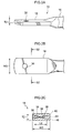
Fig. 2A is a perspective view showing the shape of an attachment portion according to the exemplary embodiment of the invention after pressing; -
Fig. 2B is a plan view showing the shape of the attachment portion according to the exemplary embodiment of the invention after pressing; -
Fig. 2C is a sectional view showing the shape of the attachment portion according to the exemplary embodiment of the invention after pressing; -
Figs. 3A to 3C are main portion perspective views showing a method of molding the attachment portion of the stabilizer bar according to the exemplary embodiment of the invention; -
Fig. 4 is a view showing how the attachment portion according to the exemplary embodiment of the invention is pressed; -
Figs. 5A to 5C are views illustrating the sectional shape of the attachment portion according to the exemplary embodiment of the invention after pressing; -
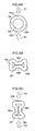
Figs. 6A to 6H are views illustrating how the sectional shape of the attachment portion according to the exemplary embodiment of the invention changes when it is pressed; -
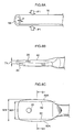
Fig. 7A is a view showing the shape of the attachment portion according to the exemplary embodiment of the invention after trimming; -
Fig. 7B is a view showing the sectional shape of the attachment portion according to the exemplary embodiment of the invention after trimming; -
Figs. 8A to 8E are views showing the basic configuration of an attachment portion of a conventional stabilizer bar; and -
Figs. 9A to 9B are views showing the state of the attachment portion of the conventional stabilizer bar when it is bent. - As shown in
Fig. 1 , astabilizer bar 10 is composed of a steel pipe material and bent to an approximate U-shape. Thestabilizer bar 10 has atorsion portion 12 of a central linear portion which is used as a torsion bar spring, curvedportions 14 formed by bending both ends of thetorsion portion 12, andarm portions 16 linearly extending from thecurved portions 14. - As shown in
Figs. 2A and 2B , flat plate-shapedattachment portions 18 having a thickness T2 are disposed at the free ends of thearm portions 16. Theattachment portions 18 are flattened by deforming the extreme ends of thearm portions 16, and throughholes 20 are formed in theattachment portions 18 to fix theattachment portions 18 to a vehicle body (not shown). - As shown in
Fig. 2C (cross section along line S2-S2 inFig. 2B ), theattachment portions 18 have a three-layered structure which is partitioned by overlappingsurfaces - That is, the three-layered structure is composed of an
upper layer portion 42 positioned on the overlappingsurfaces 36, anintermediate layer portion 44 positioned between the overlappingsurfaces lower layer portion 46 positioned under the overlapping surfaces 38.
Here, the overlappingsurfaces - As described above, the two sets of overlapping
surfaces surfaces surfaces attachment portion 18 is cut to the cut width W2. - As a result, since the pipe material can maintain the mechanical strength to withstand bending, the through
holes 20 are not positionally offset even if throughholes 20 are formed in theattachment portions 18 and then theattachment portions 18 are bent.
Further, since the thickness T2 of theattachment portions 18 can be increased to twice or more the wall thickness a of the pipe material by configuring theattachment portions 18 as a three-layered structure, the strength of theattachment portions 18 can be increased. - Next, a method of processing the
attachment portions 18 will be explained.
First, first processing is executed to deform each free end of thearm portions 16 as shown inFig. 3A in the directions of arrows P1.
That is, thearm portion 16 is fixed laterally, and the free end of thearm portion 16 is restricted from expanding in a lateral direction. Specifically, the free end of thearm portion 16 is restricted so that theright side 16R and theleft side 16L of the pipe material do not exceed the outer diameter of thearm portion 16 when viewed from an end face thereof. - Then, the
upper part 16U and thelower part 16D of the pipe material are compressed in the direction of the arrow P1 (vertical direction). Here, theupper part 16U of the pipe material is bent downward and deformed in a downwardly recessed shape. Likewise, thelower part 16D of the pipe material is bent upward and deformed in an upwardly recessed shape. - As a result, the outer peripheral surfaces of the
right side 16R and theleft side 16L of the pipe material of the free end of thearm portion 16 are formed as parallel planes as shown inFig. 3B , and theupper pipe material 16U and thelower pipe material 16D are formed in a concavely bent sectional shape. Note that the inner peripheral surface 16I of the pipe material of thearm portion 16 is extended linearly in a direction parallel to concave bottom surfaces andforms overlapping surfaces 28. Hereinafter, this shape is called an H-shape. - Next, as shown in
Fig. 3C , thearm portion 16 is rotated 90° in the direction of the arrows shown inFig. 3B , such that the concave portions positioned at the top and bottom of the H-shape are positioned to the right and left, and thearm portion 16 is pressed in the direction of arrows P2. - Specifically, as shown in
Fig. 4 , thepipe materials arm portion 16 formed in the H-shape are disposed in a vertical direction and are flattened by deformation in the direction of the arrow P2 by apress machine 30. - The
press machine 30 is a generally widely-used press machine and sets the free end of thearm portion 16 in alower mold 32 as a fixed unit and presses the free end by moving anupper mold 34 as a moving unit in the direction of the arrow P2.
With this operation, the free end of thearm portion 16 is pressed and deformed from the H-shape into a flat plate shape. - That is, as shown in
Fig. 5A , theattachment portion 18 after it is pressed by thepress machine 30 is deformed in the vertical direction and formed in a flat plate shape.
Here, as shown inFig. 5B , expandingportions 18A, which are symmetrically expanded to left and right, are formed at theattachment portion 18 in a direction (width direction) orthogonal to a center axis X1 of the arm portion 16 (width dimension: W3). Theattachment portion 18 can be finished to a cut width W2 by cutting and removing the expandingportions 18A along cutting lines 82. - Note that as shown in
Fig. 5C (cross section along line S2-S2 inFig. 5B ), in the cross section ofattachment portion 18, since the projecting length of thebent surfaces portions 18A are cut and removed along the cutting lines 82. - Here, the cross sectional shape of the
attachment portion 18 is explained.
At the free end of thearm portion 16 having a circular cross section as shown inFig. 6A before it is pressed, thepipe materials pipe materials pipe materials arm portion 16 is formed in the H-shape shown inFig. 6B . Here, the inner peripheral surfaces 16I of theconcave portions surface 28. - Next, as shown in
Fig. 6C , theattachment portion 16 formed in the H-shape is rotated 90° and set in thepress machine 30 described above. As shown inFig. 6D , thepress machine 30 applies a force from the direction of P2 and deforms thepipe materials concave portions - As a result, the
concave portions concave portions pipe material 16R acting as the upper layer portion from the upper surfaces thereof and thepipe material 16L acting as the lower layer portion from the lower surfaces thereof, as shown inFig. 6E . - Finally, as shown in
Fig. 6F , theupper part 16U and thelower part 16D forms the intermediate layer portion, thepipe material 16R is deformed at the upper side of the intermediate layer and forms the upper layer portion, and thepipe material 16L is deformed at the lower side of the intermediate layer and forms the lower layer portion, whereby the pressing process is finished. Here, the overlappingsurfaces - Note that, in
Figs. 6D and 6E , any one of theconcave portions concave portions concave portions concave portions surfaces Fig. 6G . - Further, as shown in, for example,
Fig. 6H , a position, at which theconcave portions surfaces - Finally, as shown in
Fig. 7A , the processing of theattachment portion 18 is finished by subjecting it to the pressing processing and trimming processing. Theattachment portions 18 that have been subjected to the processing are required to have the width W2, and the throughholes 20 are formed in the end portions of theattachment portions 18.
Claims (6)
- A stabilizer bar comprising attachment portions formed in a flattened three-regioned structure by deforming and compressing the end portions of a pipe material for forming the stabilizer bar, the three regions being divided by respective overlapping surfaces.
- The stabilizer bar of claim 1, wherein the overlapping surfaces have an X-shaped cross section.
- The stabilizer bar of claim 1, wherein the overlapping surfaces have a Y-shaped cross section.
- The stabilizer bar of claim 1, wherein the thickness of each of the attachment portions is twice or more the wall thickness of the pipe material.
- The stabilizer bar of claim 2, wherein the thickness of each of the attachment portions is twice or more the wall thickness of the pipe material.
- The stabilizer bar of claim 3, wherein the thickness of each of the attachment portions is twice or more the wall thickness of the pipe material.
Priority Applications (2)
| Application Number | Priority Date | Filing Date | Title |
|---|---|---|---|
| DE9816127T DE09816127T1 (en) | 2008-09-25 | 2009-09-18 | HOLLOW STABILISATOR |
| PL09816127T PL2338710T3 (en) | 2008-09-25 | 2009-09-18 | Hollow stabilizer |
Applications Claiming Priority (2)
| Application Number | Priority Date | Filing Date | Title |
|---|---|---|---|
| JP2008245725A JP4714252B2 (en) | 2008-09-25 | 2008-09-25 | Hollow stabilizer |
| PCT/JP2009/066384 WO2010035712A1 (en) | 2008-09-25 | 2009-09-18 | Hollow stabilizer |
Publications (3)
| Publication Number | Publication Date |
|---|---|
| EP2338710A1 true EP2338710A1 (en) | 2011-06-29 |
| EP2338710A4 EP2338710A4 (en) | 2012-04-18 |
| EP2338710B1 EP2338710B1 (en) | 2016-12-14 |
Family
ID=42059711
Family Applications (1)
| Application Number | Title | Priority Date | Filing Date |
|---|---|---|---|
| EP09816127.6A Active EP2338710B1 (en) | 2008-09-25 | 2009-09-18 | Hollow stabilizer |
Country Status (12)
| Country | Link |
|---|---|
| US (1) | US8490987B2 (en) |
| EP (1) | EP2338710B1 (en) |
| JP (1) | JP4714252B2 (en) |
| KR (1) | KR101231488B1 (en) |
| CN (1) | CN102164760B (en) |
| CA (1) | CA2738374C (en) |
| DE (1) | DE09816127T1 (en) |
| ES (1) | ES2368894T3 (en) |
| HU (1) | HUE032632T2 (en) |
| PL (1) | PL2338710T3 (en) |
| TW (1) | TWI373416B (en) |
| WO (1) | WO2010035712A1 (en) |
Cited By (1)
| Publication number | Priority date | Publication date | Assignee | Title |
|---|---|---|---|---|
| US11786955B2 (en) | 2018-04-05 | 2023-10-17 | Hydro Extruded Solutions As | Strut and method of manufacturing a strut |
Families Citing this family (10)
| Publication number | Priority date | Publication date | Assignee | Title |
|---|---|---|---|---|
| US20070257462A1 (en) * | 2006-05-02 | 2007-11-08 | Meritor Suspension Systems Company, Us | Die cast stabilizer bar ends |
| US8490977B2 (en) * | 2007-03-20 | 2013-07-23 | Cfph, Llc | Game broker |
| CN103562051B (en) * | 2011-04-27 | 2016-05-25 | 三菱自动车工业株式会社 | Carrier frame |
| JP2014088119A (en) * | 2012-10-30 | 2014-05-15 | Aisin Keikinzoku Co Ltd | Door beam for vehicle |
| JP5961223B2 (en) * | 2014-04-10 | 2016-08-02 | 日本発條株式会社 | Pipe-shaped member and end sealing method thereof |
| CA3111487C (en) * | 2018-09-04 | 2023-12-12 | The Unimax Corporation | Coined drawbars for drawbar assemblies |
| EP3943209B1 (en) * | 2019-03-18 | 2024-02-28 | NHK Spring Co., Ltd. | Method for manufacturing stabilizer |
| JP7413340B2 (en) * | 2021-12-24 | 2024-01-15 | 日本発條株式会社 | Stabilizer manufacturing method |
| JP7413341B2 (en) * | 2021-12-24 | 2024-01-15 | 日本発條株式会社 | Stabilizer manufacturing method |
| NO349132B1 (en) * | 2024-03-22 | 2025-10-13 | Hydro Extruded Solutions As | Method and apparatus for forming a strut |
Family Cites Families (13)
| Publication number | Priority date | Publication date | Assignee | Title |
|---|---|---|---|---|
| US2595695A (en) * | 1947-09-24 | 1952-05-06 | Justrite Manufacturing Co | Tubular aluminum bail with reinforcing inserts at ends |
| JPS55153208U (en) * | 1979-04-20 | 1980-11-05 | ||
| JPS55153208A (en) * | 1979-05-15 | 1980-11-29 | Mitsubishi Electric Corp | Drawer type breaker |
| JPS5774807U (en) * | 1980-10-25 | 1982-05-08 | ||
| JPS5774807A (en) * | 1980-10-29 | 1982-05-11 | Canon Inc | Reproducing method of magnetic recording signal |
| JPS58133909A (en) * | 1982-02-01 | 1983-08-09 | Nhk Spring Co Ltd | End forming method of stabilizer for vehicle suspension |
| JPS6186036A (en) * | 1984-10-03 | 1986-05-01 | Mitsubishi Heavy Ind Ltd | Flattening work method of pipe end and it's die |
| JPH0223366A (en) | 1988-07-12 | 1990-01-25 | Mita Ind Co Ltd | Image forming method |
| JPH02283519A (en) * | 1989-04-24 | 1990-11-21 | Nhk Spring Co Ltd | Hollow stabilizer for vehicle |
| JPH0757396B2 (en) * | 1991-04-08 | 1995-06-21 | 日本軽金属株式会社 | Method for forming crushed flat part of hollow metal profile |
| ITBS20040021A1 (en) | 2004-02-20 | 2004-05-20 | Reti Gritti Spa | METHOD TO APPLY A PORTION OF A TUBULAR ELEMENT |
| US7509463B2 (en) | 2005-12-01 | 2009-03-24 | Sony Computer Entertainment, Inc. | Cell processor atomic compare and swap using dedicated synergistic processor element |
| JP2008143313A (en) * | 2006-12-08 | 2008-06-26 | Mitsubishi Steel Mfg Co Ltd | Hollow stabilizer |
-
2008
- 2008-09-25 JP JP2008245725A patent/JP4714252B2/en active Active
-
2009
- 2009-09-18 US US13/120,620 patent/US8490987B2/en active Active
- 2009-09-18 CN CN200980137619.4A patent/CN102164760B/en active Active
- 2009-09-18 HU HUE09816127A patent/HUE032632T2/en unknown
- 2009-09-18 EP EP09816127.6A patent/EP2338710B1/en active Active
- 2009-09-18 WO PCT/JP2009/066384 patent/WO2010035712A1/en not_active Ceased
- 2009-09-18 CA CA2738374A patent/CA2738374C/en active Active
- 2009-09-18 ES ES09816127.6T patent/ES2368894T3/en active Active
- 2009-09-18 DE DE9816127T patent/DE09816127T1/en active Pending
- 2009-09-18 KR KR1020117009233A patent/KR101231488B1/en active Active
- 2009-09-18 PL PL09816127T patent/PL2338710T3/en unknown
- 2009-09-23 TW TW098132063A patent/TWI373416B/en active
Non-Patent Citations (2)
| Title |
|---|
| No further relevant documents disclosed * |
| See also references of WO2010035712A1 * |
Cited By (1)
| Publication number | Priority date | Publication date | Assignee | Title |
|---|---|---|---|---|
| US11786955B2 (en) | 2018-04-05 | 2023-10-17 | Hydro Extruded Solutions As | Strut and method of manufacturing a strut |
Also Published As
| Publication number | Publication date |
|---|---|
| CA2738374C (en) | 2013-11-19 |
| EP2338710B1 (en) | 2016-12-14 |
| DE09816127T1 (en) | 2012-01-12 |
| WO2010035712A1 (en) | 2010-04-01 |
| CN102164760A (en) | 2011-08-24 |
| CA2738374A1 (en) | 2010-01-04 |
| PL2338710T3 (en) | 2017-06-30 |
| ES2368894T3 (en) | 2017-05-23 |
| CN102164760B (en) | 2015-12-16 |
| ES2368894T1 (en) | 2011-11-23 |
| JP2010076540A (en) | 2010-04-08 |
| US8490987B2 (en) | 2013-07-23 |
| HUE032632T2 (en) | 2017-10-30 |
| KR20110076957A (en) | 2011-07-06 |
| JP4714252B2 (en) | 2011-06-29 |
| KR101231488B1 (en) | 2013-02-07 |
| EP2338710A4 (en) | 2012-04-18 |
| TWI373416B (en) | 2012-10-01 |
| TW201020133A (en) | 2010-06-01 |
| US20110175315A1 (en) | 2011-07-21 |
Similar Documents
| Publication | Publication Date | Title |
|---|---|---|
| EP2338710B1 (en) | Hollow stabilizer | |
| US7971466B2 (en) | Press-formed member having corner portion, press-formed member manufacturing apparatus and press-formed member manufacturing method | |
| US8291595B2 (en) | Method for production of a link rod with U-shaped cross section from sheet metal for a car multi-link axle | |
| US10207310B2 (en) | Method for manufacturing vehicle structural member | |
| EP2687390A1 (en) | Vehicular arm component and production method therefor | |
| EP2143511A1 (en) | Beam formed of a blank sheet and method for its manufacturing | |
| EP2213520B1 (en) | Energy absorber for a vehicle bumper assembly and production method therefor | |
| EP3604087B1 (en) | Vehicle structural member and method for producing same | |
| WO2014147754A1 (en) | Suspension link and method for manufacturing same | |
| US6557930B1 (en) | Multi-section support rail apparatus and method of making | |
| JP2002316228A (en) | Method of manufacturing suspension arm for vehicle | |
| EP1864725A1 (en) | Device and method for elliptically processing metal tube and metal tube product | |
| CN110494233B (en) | Front bridge and manufacturing method thereof | |
| EP4302894B1 (en) | Manufacturing method for vehicle suspension arm, and vehicle suspension arm | |
| JP5406559B2 (en) | Structural member and manufacturing method thereof | |
| JP5137237B2 (en) | Method for manufacturing vehicle suspension arm | |
| JP2005088740A (en) | Front under run protector | |
| JP4083613B2 (en) | Axle housing | |
| CN112743294B (en) | Method for manufacturing tube | |
| JP2007320343A (en) | Hollow stabilizer | |
| JP4297213B2 (en) | Manufacturing method of tubular member with flange | |
| US20250381813A1 (en) | Suspension structure for vehicle and method of manufacturing the same | |
| JP2009214714A (en) | Bumper structure | |
| CN105564173B (en) | Cross link with press-fit ball joint | |
| KR20110061391A (en) | Manufacturing method of ultra high strength steel front side member |
Legal Events
| Date | Code | Title | Description |
|---|---|---|---|
| PUAI | Public reference made under article 153(3) epc to a published international application that has entered the european phase |
Free format text: ORIGINAL CODE: 0009012 |
|
| 17P | Request for examination filed |
Effective date: 20110421 |
|
| AK | Designated contracting states |
Kind code of ref document: A1 Designated state(s): AT BE BG CH CY CZ DE DK EE ES FI FR GB GR HR HU IE IS IT LI LT LU LV MC MK MT NL NO PL PT RO SE SI SK SM TR |
|
| AX | Request for extension of the european patent |
Extension state: AL BA RS |
|
| REG | Reference to a national code |
Ref country code: FR Ref legal event code: EL |
|
| DAX | Request for extension of the european patent (deleted) | ||
| REG | Reference to a national code |
Ref country code: DE Ref legal event code: R210 Ref document number: 602009043127 Country of ref document: DE Effective date: 20120112 Ref country code: DE Ref legal event code: R210 Effective date: 20120112 |
|
| A4 | Supplementary search report drawn up and despatched |
Effective date: 20120316 |
|
| RIC1 | Information provided on ipc code assigned before grant |
Ipc: B60G 21/055 20060101AFI20120312BHEP Ipc: B21D 19/08 20060101ALI20120312BHEP Ipc: F16F 1/14 20060101ALI20120312BHEP Ipc: B21D 53/88 20060101ALI20120312BHEP |
|
| 17Q | First examination report despatched |
Effective date: 20120920 |
|
| GRAP | Despatch of communication of intention to grant a patent |
Free format text: ORIGINAL CODE: EPIDOSNIGR1 |
|
| INTG | Intention to grant announced |
Effective date: 20160707 |
|
| GRAS | Grant fee paid |
Free format text: ORIGINAL CODE: EPIDOSNIGR3 |
|
| GRAA | (expected) grant |
Free format text: ORIGINAL CODE: 0009210 |
|
| AK | Designated contracting states |
Kind code of ref document: B1 Designated state(s): AT BE BG CH CY CZ DE DK EE ES FI FR GB GR HR HU IE IS IT LI LT LU LV MC MK MT NL NO PL PT RO SE SI SK SM TR |
|
| REG | Reference to a national code |
Ref country code: GB Ref legal event code: FG4D |
|
| REG | Reference to a national code |
Ref country code: CH Ref legal event code: EP |
|
| REG | Reference to a national code |
Ref country code: IE Ref legal event code: FG4D |
|
| REG | Reference to a national code |
Ref country code: AT Ref legal event code: REF Ref document number: 853230 Country of ref document: AT Kind code of ref document: T Effective date: 20170115 |
|
| REG | Reference to a national code |
Ref country code: DE Ref legal event code: R096 Ref document number: 602009043127 Country of ref document: DE |
|
| PG25 | Lapsed in a contracting state [announced via postgrant information from national office to epo] |
Ref country code: LV Free format text: LAPSE BECAUSE OF FAILURE TO SUBMIT A TRANSLATION OF THE DESCRIPTION OR TO PAY THE FEE WITHIN THE PRESCRIBED TIME-LIMIT Effective date: 20161214 |
|
| REG | Reference to a national code |
Ref country code: LT Ref legal event code: MG4D |
|
| REG | Reference to a national code |
Ref country code: NL Ref legal event code: MP Effective date: 20161214 |
|
| PG25 | Lapsed in a contracting state [announced via postgrant information from national office to epo] |
Ref country code: LT Free format text: LAPSE BECAUSE OF FAILURE TO SUBMIT A TRANSLATION OF THE DESCRIPTION OR TO PAY THE FEE WITHIN THE PRESCRIBED TIME-LIMIT Effective date: 20161214 Ref country code: SE Free format text: LAPSE BECAUSE OF FAILURE TO SUBMIT A TRANSLATION OF THE DESCRIPTION OR TO PAY THE FEE WITHIN THE PRESCRIBED TIME-LIMIT Effective date: 20161214 Ref country code: GR Free format text: LAPSE BECAUSE OF FAILURE TO SUBMIT A TRANSLATION OF THE DESCRIPTION OR TO PAY THE FEE WITHIN THE PRESCRIBED TIME-LIMIT Effective date: 20170315 Ref country code: NO Free format text: LAPSE BECAUSE OF FAILURE TO SUBMIT A TRANSLATION OF THE DESCRIPTION OR TO PAY THE FEE WITHIN THE PRESCRIBED TIME-LIMIT Effective date: 20170314 |
|
| REG | Reference to a national code |
Ref country code: AT Ref legal event code: MK05 Ref document number: 853230 Country of ref document: AT Kind code of ref document: T Effective date: 20161214 |
|
| REG | Reference to a national code |
Ref country code: ES Ref legal event code: FG2A Ref document number: 2368894 Country of ref document: ES Kind code of ref document: T3 Effective date: 20170523 |
|
| PG25 | Lapsed in a contracting state [announced via postgrant information from national office to epo] |
Ref country code: FI Free format text: LAPSE BECAUSE OF FAILURE TO SUBMIT A TRANSLATION OF THE DESCRIPTION OR TO PAY THE FEE WITHIN THE PRESCRIBED TIME-LIMIT Effective date: 20161214 Ref country code: HR Free format text: LAPSE BECAUSE OF FAILURE TO SUBMIT A TRANSLATION OF THE DESCRIPTION OR TO PAY THE FEE WITHIN THE PRESCRIBED TIME-LIMIT Effective date: 20161214 |
|
| PG25 | Lapsed in a contracting state [announced via postgrant information from national office to epo] |
Ref country code: NL Free format text: LAPSE BECAUSE OF FAILURE TO SUBMIT A TRANSLATION OF THE DESCRIPTION OR TO PAY THE FEE WITHIN THE PRESCRIBED TIME-LIMIT Effective date: 20161214 |
|
| PG25 | Lapsed in a contracting state [announced via postgrant information from national office to epo] |
Ref country code: SK Free format text: LAPSE BECAUSE OF FAILURE TO SUBMIT A TRANSLATION OF THE DESCRIPTION OR TO PAY THE FEE WITHIN THE PRESCRIBED TIME-LIMIT Effective date: 20161214 Ref country code: EE Free format text: LAPSE BECAUSE OF FAILURE TO SUBMIT A TRANSLATION OF THE DESCRIPTION OR TO PAY THE FEE WITHIN THE PRESCRIBED TIME-LIMIT Effective date: 20161214 Ref country code: RO Free format text: LAPSE BECAUSE OF FAILURE TO SUBMIT A TRANSLATION OF THE DESCRIPTION OR TO PAY THE FEE WITHIN THE PRESCRIBED TIME-LIMIT Effective date: 20161214 Ref country code: IS Free format text: LAPSE BECAUSE OF FAILURE TO SUBMIT A TRANSLATION OF THE DESCRIPTION OR TO PAY THE FEE WITHIN THE PRESCRIBED TIME-LIMIT Effective date: 20170414 |
|
| REG | Reference to a national code |
Ref country code: FR Ref legal event code: PLFP Year of fee payment: 9 |
|
| PG25 | Lapsed in a contracting state [announced via postgrant information from national office to epo] |
Ref country code: PT Free format text: LAPSE BECAUSE OF FAILURE TO SUBMIT A TRANSLATION OF THE DESCRIPTION OR TO PAY THE FEE WITHIN THE PRESCRIBED TIME-LIMIT Effective date: 20170414 Ref country code: BG Free format text: LAPSE BECAUSE OF FAILURE TO SUBMIT A TRANSLATION OF THE DESCRIPTION OR TO PAY THE FEE WITHIN THE PRESCRIBED TIME-LIMIT Effective date: 20170314 Ref country code: SM Free format text: LAPSE BECAUSE OF FAILURE TO SUBMIT A TRANSLATION OF THE DESCRIPTION OR TO PAY THE FEE WITHIN THE PRESCRIBED TIME-LIMIT Effective date: 20161214 Ref country code: AT Free format text: LAPSE BECAUSE OF FAILURE TO SUBMIT A TRANSLATION OF THE DESCRIPTION OR TO PAY THE FEE WITHIN THE PRESCRIBED TIME-LIMIT Effective date: 20161214 Ref country code: BE Free format text: LAPSE BECAUSE OF FAILURE TO SUBMIT A TRANSLATION OF THE DESCRIPTION OR TO PAY THE FEE WITHIN THE PRESCRIBED TIME-LIMIT Effective date: 20161214 |
|
| REG | Reference to a national code |
Ref country code: DE Ref legal event code: R097 Ref document number: 602009043127 Country of ref document: DE |
|
| PGFP | Annual fee paid to national office [announced via postgrant information from national office to epo] |
Ref country code: NL Payment date: 20170814 Year of fee payment: 9 |
|
| PLBE | No opposition filed within time limit |
Free format text: ORIGINAL CODE: 0009261 |
|
| STAA | Information on the status of an ep patent application or granted ep patent |
Free format text: STATUS: NO OPPOSITION FILED WITHIN TIME LIMIT |
|
| REG | Reference to a national code |
Ref country code: HU Ref legal event code: AG4A Ref document number: E032632 Country of ref document: HU |
|
| 26N | No opposition filed |
Effective date: 20170915 |
|
| PG25 | Lapsed in a contracting state [announced via postgrant information from national office to epo] |
Ref country code: DK Free format text: LAPSE BECAUSE OF FAILURE TO SUBMIT A TRANSLATION OF THE DESCRIPTION OR TO PAY THE FEE WITHIN THE PRESCRIBED TIME-LIMIT Effective date: 20161214 |
|
| PGFP | Annual fee paid to national office [announced via postgrant information from national office to epo] |
Ref country code: BE Payment date: 20170814 Year of fee payment: 9 |
|
| PG25 | Lapsed in a contracting state [announced via postgrant information from national office to epo] |
Ref country code: SI Free format text: LAPSE BECAUSE OF FAILURE TO SUBMIT A TRANSLATION OF THE DESCRIPTION OR TO PAY THE FEE WITHIN THE PRESCRIBED TIME-LIMIT Effective date: 20161214 |
|
| REG | Reference to a national code |
Ref country code: CH Ref legal event code: PL |
|
| PG25 | Lapsed in a contracting state [announced via postgrant information from national office to epo] |
Ref country code: MC Free format text: LAPSE BECAUSE OF FAILURE TO SUBMIT A TRANSLATION OF THE DESCRIPTION OR TO PAY THE FEE WITHIN THE PRESCRIBED TIME-LIMIT Effective date: 20161214 |
|
| REG | Reference to a national code |
Ref country code: IE Ref legal event code: MM4A |
|
| PG25 | Lapsed in a contracting state [announced via postgrant information from national office to epo] |
Ref country code: LU Free format text: LAPSE BECAUSE OF NON-PAYMENT OF DUE FEES Effective date: 20170918 |
|
| PG25 | Lapsed in a contracting state [announced via postgrant information from national office to epo] |
Ref country code: CH Free format text: LAPSE BECAUSE OF NON-PAYMENT OF DUE FEES Effective date: 20170930 Ref country code: LI Free format text: LAPSE BECAUSE OF NON-PAYMENT OF DUE FEES Effective date: 20170930 Ref country code: IE Free format text: LAPSE BECAUSE OF NON-PAYMENT OF DUE FEES Effective date: 20170918 |
|
| REG | Reference to a national code |
Ref country code: FR Ref legal event code: PLFP Year of fee payment: 10 |
|
| PG25 | Lapsed in a contracting state [announced via postgrant information from national office to epo] |
Ref country code: MT Free format text: LAPSE BECAUSE OF NON-PAYMENT OF DUE FEES Effective date: 20170918 |
|
| PG25 | Lapsed in a contracting state [announced via postgrant information from national office to epo] |
Ref country code: CY Free format text: LAPSE BECAUSE OF NON-PAYMENT OF DUE FEES Effective date: 20161214 |
|
| PG25 | Lapsed in a contracting state [announced via postgrant information from national office to epo] |
Ref country code: MK Free format text: LAPSE BECAUSE OF FAILURE TO SUBMIT A TRANSLATION OF THE DESCRIPTION OR TO PAY THE FEE WITHIN THE PRESCRIBED TIME-LIMIT Effective date: 20161214 |
|
| PGFP | Annual fee paid to national office [announced via postgrant information from national office to epo] |
Ref country code: DE Payment date: 20250730 Year of fee payment: 17 |
|
| PGFP | Annual fee paid to national office [announced via postgrant information from national office to epo] |
Ref country code: PL Payment date: 20250806 Year of fee payment: 17 Ref country code: TR Payment date: 20250911 Year of fee payment: 17 Ref country code: IT Payment date: 20250825 Year of fee payment: 17 |
|
| PGFP | Annual fee paid to national office [announced via postgrant information from national office to epo] |
Ref country code: HU Payment date: 20250828 Year of fee payment: 17 Ref country code: GB Payment date: 20250731 Year of fee payment: 17 |
|
| PGFP | Annual fee paid to national office [announced via postgrant information from national office to epo] |
Ref country code: FR Payment date: 20250808 Year of fee payment: 17 |
|
| PGFP | Annual fee paid to national office [announced via postgrant information from national office to epo] |
Ref country code: CZ Payment date: 20250905 Year of fee payment: 17 |
|
| PGFP | Annual fee paid to national office [announced via postgrant information from national office to epo] |
Ref country code: ES Payment date: 20251013 Year of fee payment: 17 |